EP3396687A1 - Energizing method of a transformer, and transformer connection assembly - Google Patents
Energizing method of a transformer, and transformer connection assembly Download PDFInfo
- Publication number
- EP3396687A1 EP3396687A1 EP17168735.3A EP17168735A EP3396687A1 EP 3396687 A1 EP3396687 A1 EP 3396687A1 EP 17168735 A EP17168735 A EP 17168735A EP 3396687 A1 EP3396687 A1 EP 3396687A1
- Authority
- EP
- European Patent Office
- Prior art keywords
- coils
- groups
- transformer
- supply voltage
- entirety
- Prior art date
- Legal status (The legal status is an assumption and is not a legal conclusion. Google has not performed a legal analysis and makes no representation as to the accuracy of the status listed.)
- Granted
Links
Images
Classifications
-
- H—ELECTRICITY
- H01—ELECTRIC ELEMENTS
- H01F—MAGNETS; INDUCTANCES; TRANSFORMERS; SELECTION OF MATERIALS FOR THEIR MAGNETIC PROPERTIES
- H01F27/00—Details of transformers or inductances, in general
- H01F27/42—Circuits specially adapted for the purpose of modifying, or compensating for, electric characteristics of transformers, reactors, or choke coils
-
- H—ELECTRICITY
- H01—ELECTRIC ELEMENTS
- H01F—MAGNETS; INDUCTANCES; TRANSFORMERS; SELECTION OF MATERIALS FOR THEIR MAGNETIC PROPERTIES
- H01F27/00—Details of transformers or inductances, in general
- H01F27/34—Special means for preventing or reducing unwanted electric or magnetic effects, e.g. no-load losses, reactive currents, harmonics, oscillations, leakage fields
-
- H—ELECTRICITY
- H01—ELECTRIC ELEMENTS
- H01F—MAGNETS; INDUCTANCES; TRANSFORMERS; SELECTION OF MATERIALS FOR THEIR MAGNETIC PROPERTIES
- H01F29/00—Variable transformers or inductances not covered by group H01F21/00
- H01F29/02—Variable transformers or inductances not covered by group H01F21/00 with tappings on coil or winding; with provision for rearrangement or interconnection of windings
-
- H—ELECTRICITY
- H02—GENERATION; CONVERSION OR DISTRIBUTION OF ELECTRIC POWER
- H02M—APPARATUS FOR CONVERSION BETWEEN AC AND AC, BETWEEN AC AND DC, OR BETWEEN DC AND DC, AND FOR USE WITH MAINS OR SIMILAR POWER SUPPLY SYSTEMS; CONVERSION OF DC OR AC INPUT POWER INTO SURGE OUTPUT POWER; CONTROL OR REGULATION THEREOF
- H02M5/00—Conversion of AC power input into AC power output, e.g. for change of voltage, for change of frequency, for change of number of phases
- H02M5/02—Conversion of AC power input into AC power output, e.g. for change of voltage, for change of frequency, for change of number of phases without intermediate conversion into DC
- H02M5/04—Conversion of AC power input into AC power output, e.g. for change of voltage, for change of frequency, for change of number of phases without intermediate conversion into DC by static converters
- H02M5/10—Conversion of AC power input into AC power output, e.g. for change of voltage, for change of frequency, for change of number of phases without intermediate conversion into DC by static converters using transformers
-
- H—ELECTRICITY
- H02—GENERATION; CONVERSION OR DISTRIBUTION OF ELECTRIC POWER
- H02M—APPARATUS FOR CONVERSION BETWEEN AC AND AC, BETWEEN AC AND DC, OR BETWEEN DC AND DC, AND FOR USE WITH MAINS OR SIMILAR POWER SUPPLY SYSTEMS; CONVERSION OF DC OR AC INPUT POWER INTO SURGE OUTPUT POWER; CONTROL OR REGULATION THEREOF
- H02M1/00—Details of apparatus for conversion
- H02M1/32—Means for protecting converters other than automatic disconnection
-
- H—ELECTRICITY
- H02—GENERATION; CONVERSION OR DISTRIBUTION OF ELECTRIC POWER
- H02M—APPARATUS FOR CONVERSION BETWEEN AC AND AC, BETWEEN AC AND DC, OR BETWEEN DC AND DC, AND FOR USE WITH MAINS OR SIMILAR POWER SUPPLY SYSTEMS; CONVERSION OF DC OR AC INPUT POWER INTO SURGE OUTPUT POWER; CONTROL OR REGULATION THEREOF
- H02M1/00—Details of apparatus for conversion
- H02M1/36—Means for starting or stopping converters
Definitions
- aspects of the present disclosure relate generally to an energizing method of a transformer, and to a transformer connection assembly having an energizing controller configured to perform an energizing method.
- a transient high inrush current flows upon connection of the transformer to a supply voltage when the transformer is in an unenergized, or unmagnetized, state.
- the high inrush current flows as a result from a magnetic saturation in the transformer core.
- the core is sufficiently magnetized, and the current flowing into the primary side during the regular operation is usually not nearly as high as a possible inrush current.
- Supply systems upstream of the point of connection of the supply voltage to the primary side of the transformer may comprise protection installations for limiting a current which exceeds a certain value.
- protection installations can disconnect the supply voltage immediately in the case that the inrush current is too high. Due to the transient nature of the inrush current, also a DC component is induced on the supply side of the installation, which can make some protection installations to operate, i. e. to disrupt the connection.
- the inrush current is limited by the coil impedance on the primary side.
- Some transformers have multiple groups of primary-side coils connected in parallel. Thus, the equivalent impedance of the coil groups may become relatively low, which further raises the transient amplitude of an inrush current upon connecting an unenergized transformer to the supply voltage.
- Conventional methods and installations for limiting an inrush current of a transformer include an introduction of an air gap into the magnetic core, synchronizing the time of connection to a phase of the supply voltage, and/or a pre-energization by auxiliary circuits.
- a synchronization to the phase of the primary-side voltage is a costly and complex approach, since a proper measurement of the phase and a fast controlled switching is involved.
- an auxiliary circuit for pre-energizing the core needs space for the auxiliary windings, and a connection operation involves several steps which have to be carried out by various devices.
- An object of the disclosure is to provide a simplified energizing method for a transformer and/or to provide a simplified transformer connection assembly, each being cost-efficient and reliably suppressing an inrush current to an allowable amount.
- an energizing method according to claim 1, and a transformer connection assembly according to claim 10 are provided.
- an energizing method of a transformer comprises at least two groups of coils forming primary transformer windings, and at least one secondary transformer winding.
- the windings are typically arranged on a common transformer core, e. g. made of a ferromagnetic material such as iron, in order to magnetically couple the primary transformer windings to the at least one secondary transformer winding.
- the transformer core is a gapless core, i. e. a core in which no functional air gap for intendedly enhancing the reluctance in the magnetic circuit of the transformer, is provided.
- first a supply voltage is supplied to a first number of the groups of coils for a predetermined amount of time.
- the first number of coils is less than the entirety of groups of coils.
- the supply voltage is supplied to the entirety of groups of coils.
- supplying the supply voltage to the entirety of groups of coils is referred to as a "nominal operation" of the transformer.
- the nominal operation of the transformer usually is a standard operation of the transformer, i. e. an operation or operational state in which the rated values of the transformer are achieved.
- the standard operation none of the groups of coils are inoperational within the meaning that there are no coils on the primary side that are used solely in a distinct pre-magnetization operation such as in an auxiliary pre-magnetizing circuit.
- the inrush current is reliably limited to a non-excessive amount, and devices such as protection devices can be prevented from erroneously being activated due to an inrush current upon connecting a transformer to a supply voltage.
- devices such as protection devices can be prevented from erroneously being activated due to an inrush current upon connecting a transformer to a supply voltage.
- a space-consuming and complex auxiliary pre-magnetizing circuit need not be provided.
- a complex phase synchronization of a switching time or connection time is dispensable. The method may help to achieve reliable results without having to pay attention to a phase of the supply voltage at any point in time.
- the groups of coils each may comprise a same amount of coil windings, or the amount of coil windings may differ.
- a first number of groups of coils being less than the entirety of groups of coils may be just one group of coils less than the entirety of groups.
- the first number may, of course, be two or more groups of coils less than the entirety of groups.
- the first number may be selected according to an equivalent impedance of the first number of groups of coils, such that when supplying the supply voltage having a predetermined amplitude to the first number of the groups of coils in a substantially unenergized (unmagnetized) state, a predetermined inrush AC current is not exceeded and/or DC component requirements are met.
- the predetermined amplitude of the supply voltage is optionally a root mean square amplitude of a single-phase AC electric supply voltage.
- the predetermined inrush current is typically selected such that a rated current or a specificied maximum transient current of primary-side electrical components is not exceeded, and/or or DC component requirements are met.
- primary-side electrical components include, but are not limited to, protection devices arranged to interrupt an excessive current flowing into the primary side of the transformer.
- the predetermined amount of time for supplying the supply voltage to the first number of the groups of coils is selected such that a sufficient magnetic energization (i.e. a sufficient magnetization) of the groups of coils forming the primary transformer windings can be reasonably assumed.
- a sufficient magnetic energization may be assumed, for example, when in a given transformer, the common magnetic flux, which is caused by supplying the supply voltage to the first number of the groups of coils, has reached at least 50% or at least 60% or at least 70% of a magnetic flux during the nominal operation of the transformer.
- a sufficient magnetic energization may be assumed, for example, when in a given transformer the current that flows into the first number of groups of coils has substantially reached a steady state.
- the exemplary conditions for a sufficient magnetic energization are merely examples, and that neither of the technical quantities taken as an example (e. g. the amount of the common magnetic flux, the current flowing into the first number of groups of coils) needs to be actually measured.
- the conditions may be pre-calculated, and a reasonable value may be specified for the predetermined amount of time of supplying the first voltage to the first number of the groups of coils.
- a non-limiting example for the predetermined amount of time of supplying the first voltage to the first number of the groups of coils, when using the method in energizing a typical traction transformer of an AC electric train, is, for example, more than 0.04 seconds and less than 5 seconds.
- the predetermined amount of time may however be in a range of up to 30 seconds, for example.
- the supply voltage to be supplied to the entirety of the groups of coils is a supply voltage from the same voltage source as the supply voltage, which is to be supplied to less than the entirety of the groups of coils.
- the supply voltage to be supplied to the entirety of the groups of coils is the same supply voltage, in amplitude and phase, as the supply voltage which is to be supplied to less than the entirety of the groups of coils.
- the supply voltage from the same voltage source and/or the same supply voltage may simply be switched, when transitioning from the method step of supplying the supply voltage to the first number of the groups of coils to the method step of supplying the supply voltage to the entirety of the groups of coils.
- the inrush current is reliably limited, and due to magnetizing the groups of coils by passing the common magnetic flux in the method step of supplying the supply voltage to the first number of the groups of coils, no further inrush current will be produced by the subsequent method step(s).
- supplying the supply voltage to the first number of the groups of coils involves switching a voltage from a voltage terminal to the first number of coils.
- supplying the supply voltage to the entirety of the groups of coils involves switching a voltage from a voltage terminal to the entirety of the groups of coils. Switching the supply voltage from the voltage terminal for performing the method involves a controlled operation.
- a transition from supplying the supply voltage to less than the entirety of the groups of coils for a predetermined amount of time to supplying the supply voltage to the entirety of the groups of coils is performed in an unsynchronized manner with respect to the phase of the supply voltage.
- a phase of the supply need not be taken care of when transitioning from one stage of the method to the other, e. g. when switching the voltage from the voltage terminal to the entirety of the groups of coils after the predetermined amount of time has passed. Without any complex phase synchronization, the inrush current in the first stage of the method is reliably limited, and no further inrush current will be produced in the subsequent stage of the method.
- the groups of coils each have the same number of coil windings. This allows for a particularly simple configuration, while yet suppressing the inrush current in a reliable manner. It is however noted, that according to other aspects, the groups of coils may have different numbers of coil windings.
- a ratio of the first number of groups of coils to the entirety (i.e. entire number) of groups of coils is less than 1, optionally less than 1/12 or 1/16 or less than 1/16.
- the inrush current may be limited to a particularly low value; yet, due to the common magnetic flux caused in the first stage of the method, a further inrush current occurring when transitioning to the nominal operation of the transformer is suppressed.
- a transformer connection assembly comprises a transformer having at least two groups of coils forming primary transformer windings, and at least one secondary transformer winding.
- the groups of coils are arranged on the transformer such that in an operational state of the transformer, the groups of coils are passed through by a common magnetic flux.
- the transformer connection assembly further comprises a first switch, wherein in a closed state of the first switch, a supply voltage terminal is connected to a first number of the groups of coils, the first number being less than the entirety or entire number of groups of coils.
- the transformer connection assembly further comprises a second switch, wherein in a closed state of the second switch, the supply voltage terminal is connected to the entirety of the groups of coils.
- the transformer connection assembly comprises an energizing controller.
- the energizing controller is configured to perform an energizing method as described herein.
- the transformer in a method disclosed herein or a transformer connection assembly disclosed herein, is a single-phase transformer.
- the single-phase transformer is a traction transformer for an electric train traction device, also known as rolling stock.
- the transformer in a method disclosed herein or a transformer connection assembly disclosed herein, is a multi-phase transformer, optionally a distribution transformer.
- the transformer in a method disclosed herein or a transformer connection assembly disclosed herein, is an insulation transformer.
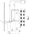
- a transformer comprises a primary transformer winding 5 on the primary side of the transformer and a secondary transformer winding 6 on the secondary side of the transformer.
- the secondary transformer winding 6 comprises multiple coils, but is not limited thereto.
- the primary transformer winding 5 has at least two groups 5a, 5b of coils which, in their entirety, form the primary transformer winding.
- the transformer typically comprises a core (not shown) on which the primary and secondary transformer windings 5, 6 are wound.
- the at least two groups 5a, 5b of coils forming the primary transformer winding are arranged and configured such that in an operational state of the transformer, the groups 5a, 5b are passed through by a common magnetic flux.
- all of coils that form the groups 5a, 5b of coils are connected or connectible in parallel to each other.
- the equivalent impedance of the entirety 5a, 5b of the groups of coils becomes low, when being commonly connected in parallel.
- the transformer may, for example, be a traction transformer used in an AC electric train.
- the traction transformer may be suited to accommodate different primary-side voltages (supply voltages) and different primary-side frequencies, such as voltages of up to 25 kV and having frequencies of 16.7 Hz up to 50 Hz, for example.
- the primary side of the transformer is connectible to a catenary 1 via a pantograph 2.
- the pantograph 2 in Fig. 1 serves as a supply voltage terminal for supplying a supply voltage to the primary side of the transformer.
- a first switch 3 and a second switch 4 are provided.
- the first switch 3 may typically be a main circuit breaker 3, and the second switch 4 may be an auxiliary switching device 4.
- the first and second switches 3, 4 have a rated voltage corresponding to or exceeding the voltage at the supply voltage terminal, e. g. a rated voltage of 15 kV or a rated voltage of 25 kV.
- the first switch 3 is connected such that in a closed state, the supply voltage terminal is connected to a first number 5a of the groups 5a, 5b of coils, such that the first number 5a is supplied with the supply voltage.
- the first number 5a of the groups 5a, 5b of coils is less than the entirety or entire number of the groups 5a, 5b of coils; in the non-limiting example of Fig. 1 , the first number 5a has a value of two, and the entirety of groups 5a, 5b amounts to five. That is, in the non-limiting example of Fig. 1 , a ratio of the first number 5a to the entirety 5a, 5b has a value of 2/5.
- the second switch 4 is connected such that in a closed state of the second switch 4 (in the non-limiting example of Fig. 1 , in connection with a closed state of the first switch 3 serving as the main circuit breaker), the supply voltage terminal is connected to the entirety 5a, 5b of the groups of coils.
- first switch 3 and the second switch 4 are only a non-limiting exemplary embodiment.
- the first and second switches 3, 4 may also be arranged on the transformer output side. Switches 3, 4 arranged on the output side of the transformer may have a lower voltage rating than switches 3, 4 arranged on the high-voltage side, and thus may be comparatively cheaper.
- An energizing controller 10 is provided to perform a selective switching, via a first switching line 11 and a second switching line 12, of the first and second switches 3, 4, respectively.
- the energizing controller is adapted to perform an energizing method as described herein.
- the energizing controller 10 first controls the first switch 3 to close (i.e. to close contacts). This closing operation may be performed irrespective of the phase of the voltage at the time of closing.
- the supply voltage is then supplied to the first number 5a of the groups of coils, which are connected in parallel to each other, but not to the entirety 5a, 5b of coils.
- the transient inrush current is limited by the limited equivalent impedance of the first number 5a of the groups of coils.
- the rest of the coils 5b is passed through by the common magnetic flux caused by the supply of the supply voltage to the first number 5a of the groups of coils.
- all coils 5a, 5b are pre-energized or pre-magnetized by the magnetic flux, so that their voltages have the same amplitude and the same phase as that of the first number 5a of the groups of coils.
- the energizing controller 10 keeps this state of a closed first switch 3, until a sufficient pre-magnetization of all coils on the primary side can reasonably be assumed. In the non-limiting example, the energizing controller 10 keeps the state for a delay time of approximately 1 second.
- the energizing controller 10 controls the second switch 4 to close (i.e. to close contacts).
- This closing operation may be performed irrespective of the phase of the voltage at the time of closing.
- all coils 5a, 5b on the primary side are connected in parallel, and all coils 5a, 5b on the primary side are supplied with the supply voltage. Substantially no further inrush current will occur, due to equal phase and amplitude in all coil groups 5a, 5b at this point in time, and auto-synchronization of the same supply voltage, which passes both the first switch 3 and the second switch 4, will occur.
- surge arresters 7a, 7b, 7c are installed.
- the surge arresters 7a, 7b, 7c help to avoid unwanted resonance effects and/or local over-voltages.
Landscapes
- Engineering & Computer Science (AREA)
- Power Engineering (AREA)
- Protection Of Transformers (AREA)
- Ac-Ac Conversion (AREA)
Abstract
Description
- Aspects of the present disclosure relate generally to an energizing method of a transformer, and to a transformer connection assembly having an energizing controller configured to perform an energizing method.
- In a transformer, for example a traction transformer used in electric railway propulsion vehicles (rolling stock) such as locomotive or rail coaches, a transient high inrush current flows upon connection of the transformer to a supply voltage when the transformer is in an unenergized, or unmagnetized, state. The high inrush current flows as a result from a magnetic saturation in the transformer core. During the further regular operation of the transformer, the core is sufficiently magnetized, and the current flowing into the primary side during the regular operation is usually not nearly as high as a possible inrush current.
- Supply systems upstream of the point of connection of the supply voltage to the primary side of the transformer may comprise protection installations for limiting a current which exceeds a certain value. For example, such protection installations can disconnect the supply voltage immediately in the case that the inrush current is too high. Due to the transient nature of the inrush current, also a DC component is induced on the supply side of the installation, which can make some protection installations to operate, i. e. to disrupt the connection.
- The inrush current is limited by the coil impedance on the primary side. Some transformers have multiple groups of primary-side coils connected in parallel. Thus, the equivalent impedance of the coil groups may become relatively low, which further raises the transient amplitude of an inrush current upon connecting an unenergized transformer to the supply voltage.
- Conventional methods and installations for limiting an inrush current of a transformer include an introduction of an air gap into the magnetic core, synchronizing the time of connection to a phase of the supply voltage, and/or a pre-energization by auxiliary circuits.
- Introducing an air gap involves the use of a special clamping structure for the magnetic core having the air gap, which is more complex and costly than a standard stacked core.
- A synchronization to the phase of the primary-side voltage is a costly and complex approach, since a proper measurement of the phase and a fast controlled switching is involved. Likewise, an auxiliary circuit for pre-energizing the core needs space for the auxiliary windings, and a connection operation involves several steps which have to be carried out by various devices.
- An object of the disclosure is to provide a simplified energizing method for a transformer and/or to provide a simplified transformer connection assembly, each being cost-efficient and reliably suppressing an inrush current to an allowable amount.
- In view of the above, an energizing method according to
claim 1, and a transformer connection assembly according toclaim 10 are provided. - According to a first aspect of the disclosure, an energizing method of a transformer is provided. The transformer comprises at least two groups of coils forming primary transformer windings, and at least one secondary transformer winding.
- The windings are typically arranged on a common transformer core, e. g. made of a ferromagnetic material such as iron, in order to magnetically couple the primary transformer windings to the at least one secondary transformer winding. In embodiments, the transformer core is a gapless core, i. e. a core in which no functional air gap for intendedly enhancing the reluctance in the magnetic circuit of the transformer, is provided.
- In the method, first a supply voltage is supplied to a first number of the groups of coils for a predetermined amount of time. The first number of coils is less than the entirety of groups of coils. By supplying the supply voltage to the first number of the groups of coils, a common magnetic flux is passed through the groups of coils.
- After the predetermined amount of time has passed, the supply voltage is supplied to the entirety of groups of coils. In the following, supplying the supply voltage to the entirety of groups of coils is referred to as a "nominal operation" of the transformer. The nominal operation of the transformer usually is a standard operation of the transformer, i. e. an operation or operational state in which the rated values of the transformer are achieved. In the standard operation, none of the groups of coils are inoperational within the meaning that there are no coils on the primary side that are used solely in a distinct pre-magnetization operation such as in an auxiliary pre-magnetizing circuit.
- By a method as described herein, the inrush current is reliably limited to a non-excessive amount, and devices such as protection devices can be prevented from erroneously being activated due to an inrush current upon connecting a transformer to a supply voltage. By a configuration as described herein, a space-consuming and complex auxiliary pre-magnetizing circuit need not be provided. Furthermore, a complex phase synchronization of a switching time or connection time is dispensable. The method may help to achieve reliable results without having to pay attention to a phase of the supply voltage at any point in time.
- In embodiments, the groups of coils each may comprise a same amount of coil windings, or the amount of coil windings may differ. A first number of groups of coils being less than the entirety of groups of coils may be just one group of coils less than the entirety of groups. The first number may, of course, be two or more groups of coils less than the entirety of groups.
- In embodiments, the first number may be selected according to an equivalent impedance of the first number of groups of coils, such that when supplying the supply voltage having a predetermined amplitude to the first number of the groups of coils in a substantially unenergized (unmagnetized) state, a predetermined inrush AC current is not exceeded and/or DC component requirements are met.
- The predetermined amplitude of the supply voltage is optionally a root mean square amplitude of a single-phase AC electric supply voltage.
- The predetermined inrush current is typically selected such that a rated current or a specificied maximum transient current of primary-side electrical components is not exceeded, and/or or DC component requirements are met. Examples of primary-side electrical components include, but are not limited to, protection devices arranged to interrupt an excessive current flowing into the primary side of the transformer.
- In embodiments, the predetermined amount of time for supplying the supply voltage to the first number of the groups of coils is selected such that a sufficient magnetic energization (i.e. a sufficient magnetization) of the groups of coils forming the primary transformer windings can be reasonably assumed.
- A sufficient magnetic energization may be assumed, for example, when in a given transformer, the common magnetic flux, which is caused by supplying the supply voltage to the first number of the groups of coils, has reached at least 50% or at least 60% or at least 70% of a magnetic flux during the nominal operation of the transformer.
- Alternatively, a sufficient magnetic energization may be assumed, for example, when in a given transformer the current that flows into the first number of groups of coils has substantially reached a steady state.
- It is to be noted that the exemplary conditions for a sufficient magnetic energization are merely examples, and that neither of the technical quantities taken as an example (e. g. the amount of the common magnetic flux, the current flowing into the first number of groups of coils) needs to be actually measured. In a given transformer, the conditions may be pre-calculated, and a reasonable value may be specified for the predetermined amount of time of supplying the first voltage to the first number of the groups of coils.
- A non-limiting example for the predetermined amount of time of supplying the first voltage to the first number of the groups of coils, when using the method in energizing a typical traction transformer of an AC electric train, is, for example, more than 0.04 seconds and less than 5 seconds. In certain applications, e. g. when a ratio of the first number of groups of coils to the entirety of groups of coils is particularly low in order to limit the inrush current to a particularly low value, the predetermined amount of time may however be in a range of up to 30 seconds, for example.
- According to further aspects, the supply voltage to be supplied to the entirety of the groups of coils is a supply voltage from the same voltage source as the supply voltage, which is to be supplied to less than the entirety of the groups of coils. Alternatively or additionally, the supply voltage to be supplied to the entirety of the groups of coils is the same supply voltage, in amplitude and phase, as the supply voltage which is to be supplied to less than the entirety of the groups of coils.
- The supply voltage from the same voltage source and/or the same supply voltage may simply be switched, when transitioning from the method step of supplying the supply voltage to the first number of the groups of coils to the method step of supplying the supply voltage to the entirety of the groups of coils. The inrush current is reliably limited, and due to magnetizing the groups of coils by passing the common magnetic flux in the method step of supplying the supply voltage to the first number of the groups of coils, no further inrush current will be produced by the subsequent method step(s).
- According to further aspects, supplying the supply voltage to the first number of the groups of coils involves switching a voltage from a voltage terminal to the first number of coils.
- Additionally, supplying the supply voltage to the entirety of the groups of coils involves switching a voltage from a voltage terminal to the entirety of the groups of coils. Switching the supply voltage from the voltage terminal for performing the method involves a controlled operation.
- According to further aspects, a transition from supplying the supply voltage to less than the entirety of the groups of coils for a predetermined amount of time to supplying the supply voltage to the entirety of the groups of coils is performed in an unsynchronized manner with respect to the phase of the supply voltage. A phase of the supply need not be taken care of when transitioning from one stage of the method to the other, e. g. when switching the voltage from the voltage terminal to the entirety of the groups of coils after the predetermined amount of time has passed. Without any complex phase synchronization, the inrush current in the first stage of the method is reliably limited, and no further inrush current will be produced in the subsequent stage of the method.
- According to further aspects, the groups of coils each have the same number of coil windings. This allows for a particularly simple configuration, while yet suppressing the inrush current in a reliable manner. It is however noted, that according to other aspects, the groups of coils may have different numbers of coil windings.
- According to further aspects, a ratio of the first number of groups of coils to the entirety (i.e. entire number) of groups of coils is less than 1, optionally less than 1/12 or 1/16 or less than 1/16. In this way, the inrush current may be limited to a particularly low value; yet, due to the common magnetic flux caused in the first stage of the method, a further inrush current occurring when transitioning to the nominal operation of the transformer is suppressed.
- According to further aspects, a transformer connection assembly comprises a transformer having at least two groups of coils forming primary transformer windings, and at least one secondary transformer winding. The groups of coils are arranged on the transformer such that in an operational state of the transformer, the groups of coils are passed through by a common magnetic flux. The transformer connection assembly further comprises a first switch, wherein in a closed state of the first switch, a supply voltage terminal is connected to a first number of the groups of coils, the first number being less than the entirety or entire number of groups of coils. The transformer connection assembly further comprises a second switch, wherein in a closed state of the second switch, the supply voltage terminal is connected to the entirety of the groups of coils. Furthermore, the transformer connection assembly comprises an energizing controller. The energizing controller is configured to perform an energizing method as described herein.
- According to further aspects, in a method disclosed herein or a transformer connection assembly disclosed herein, the transformer is a single-phase transformer. Optionally, the single-phase transformer is a traction transformer for an electric train traction device, also known as rolling stock. Alternatively, in a method disclosed herein or a transformer connection assembly disclosed herein, the transformer is a multi-phase transformer, optionally a distribution transformer. According to further aspects, in a method disclosed herein or a transformer connection assembly disclosed herein, the transformer is an insulation transformer.
- The disclosure will be described in greater detail with reference to the accompanying drawings, in which:
-
Fig. 1 is a schematic view of a transformer connection assembly for illustrating an embodiment. - Reference will now be made in detail to various aspects and embodiments. Each aspect and embodiment is provided by way of explanation and is not intended as a limitation. Features illustrated or described as a part of one aspect or embodiment may be used in conjunction with any other aspect or embodiment. It is intended that the present disclosure includes such combinations and modifications.
- In a schematic representation of a transformer connection assembly of
Fig. 1 for describing an embodiment, a transformer comprises a primary transformer winding 5 on the primary side of the transformer and a secondary transformer winding 6 on the secondary side of the transformer. - In
Fig. 1 , the secondary transformer winding 6 comprises multiple coils, but is not limited thereto. However, the primary transformer winding 5 has at least twogroups 5a, 5b of coils which, in their entirety, form the primary transformer winding. - The transformer typically comprises a core (not shown) on which the primary and
secondary transformer windings groups 5a, 5b of coils forming the primary transformer winding are arranged and configured such that in an operational state of the transformer, thegroups 5a, 5b are passed through by a common magnetic flux. In the example ofFig. 1 , all of coils that form thegroups 5a, 5b of coils are connected or connectible in parallel to each other. Thus, the equivalent impedance of theentirety 5a, 5b of the groups of coils becomes low, when being commonly connected in parallel. - The transformer may, for example, be a traction transformer used in an AC electric train. The traction transformer may be suited to accommodate different primary-side voltages (supply voltages) and different primary-side frequencies, such as voltages of up to 25 kV and having frequencies of 16.7 Hz up to 50 Hz, for example.
- In the example of
Fig. 1 , the primary side of the transformer is connectible to acatenary 1 via a pantograph 2. The pantograph 2 inFig. 1 serves as a supply voltage terminal for supplying a supply voltage to the primary side of the transformer. - A first switch 3 and a second switch 4 are provided. The first switch 3 may typically be a main circuit breaker 3, and the second switch 4 may be an auxiliary switching device 4. The first and second switches 3, 4 have a rated voltage corresponding to or exceeding the voltage at the supply voltage terminal, e. g. a rated voltage of 15 kV or a rated voltage of 25 kV.
- The first switch 3 is connected such that in a closed state, the supply voltage terminal is connected to a
first number 5a of thegroups 5a, 5b of coils, such that thefirst number 5a is supplied with the supply voltage. Thefirst number 5a of thegroups 5a, 5b of coils is less than the entirety or entire number of thegroups 5a, 5b of coils; in the non-limiting example ofFig. 1 , thefirst number 5a has a value of two, and the entirety ofgroups 5a, 5b amounts to five. That is, in the non-limiting example ofFig. 1 , a ratio of thefirst number 5a to theentirety 5a, 5b has a value of 2/5. The second switch 4 is connected such that in a closed state of the second switch 4 (in the non-limiting example ofFig. 1 , in connection with a closed state of the first switch 3 serving as the main circuit breaker), the supply voltage terminal is connected to theentirety 5a, 5b of the groups of coils. - It is noted that arranging the first switch 3 and the second switch 4 on the high-voltage side, i. e. on the side of the
groups 5a, 5b forming the primary transformer windings, is only a non-limiting exemplary embodiment. As an alternative, the first and second switches 3, 4 may also be arranged on the transformer output side. Switches 3, 4 arranged on the output side of the transformer may have a lower voltage rating than switches 3, 4 arranged on the high-voltage side, and thus may be comparatively cheaper. - An energizing
controller 10 is provided to perform a selective switching, via afirst switching line 11 and asecond switching line 12, of the first and second switches 3, 4, respectively. The energizing controller is adapted to perform an energizing method as described herein. - Starting from an open state of both switches 3, 4, in the embodiment, the energizing
controller 10 first controls the first switch 3 to close (i.e. to close contacts). This closing operation may be performed irrespective of the phase of the voltage at the time of closing. The supply voltage is then supplied to thefirst number 5a of the groups of coils, which are connected in parallel to each other, but not to theentirety 5a, 5b of coils. The transient inrush current is limited by the limited equivalent impedance of thefirst number 5a of the groups of coils. However, in the magnetic circuit, also the rest of the coils 5b is passed through by the common magnetic flux caused by the supply of the supply voltage to thefirst number 5a of the groups of coils. Thus, allcoils 5a, 5b are pre-energized or pre-magnetized by the magnetic flux, so that their voltages have the same amplitude and the same phase as that of thefirst number 5a of the groups of coils. - The energizing
controller 10 keeps this state of a closed first switch 3, until a sufficient pre-magnetization of all coils on the primary side can reasonably be assumed. In the non-limiting example, the energizingcontroller 10 keeps the state for a delay time of approximately 1 second. - Next, the energizing
controller 10 controls the second switch 4 to close (i.e. to close contacts). This closing operation may be performed irrespective of the phase of the voltage at the time of closing. Thereby, allcoils 5a, 5b on the primary side are connected in parallel, and allcoils 5a, 5b on the primary side are supplied with the supply voltage. Substantially no further inrush current will occur, due to equal phase and amplitude in allcoil groups 5a, 5b at this point in time, and auto-synchronization of the same supply voltage, which passes both the first switch 3 and the second switch 4, will occur. - The same principle is applicable using several (i.e. more than two) groups of coils that are each connected to their own high-voltage bushing. In
Fig. 1 , as an additional exemplary feature,surge arresters surge arresters
Claims (13)
- An energizing method of a transformer, the transformer comprising at least two groups (5a, 5b) of coils forming primary transformer windings (5), and at least one secondary transformer winding (6), wherein the method comprises in the stated order:a. Supplying a supply voltage to a first number (5a) of the groups (5a, 5b) of coils for a predetermined amount of time, the first number (5a) being less than the entirety of groups (5a, 5b) of coils, thereby passing a common magnetic flux through the groups (5a, 5b) of coils; andb. Supplying the supply voltage to the entirety of the groups (5a, 5b) of coils.
- The method of claim 1, wherein the supply voltage to be supplied to the entirety of the groups (5a, 5b) of coils is a supply voltage from the same voltage source as the supply voltage, which is to be supplied to less than the entirety of the groups (5a, 5b) of coils.
- The method of any one of the preceding claims, wherein the supply voltage to be supplied to the entirety of the groups (5a, 5b) of coils is the same supply voltage, in amplitude and phase, as the supply voltage which is to be supplied to less than the entirety of the groups (5a, 5b) of coils.
- The method of any one of the preceding claims, wherein supplying the supply voltage to the first number (5a) of the groups (5a, 5b) of coils involves switching a voltage from a voltage terminal to the first number (5a) of coils; and
wherein supplying the supply voltage to the entirety of the groups (5a, 5b) of coils involves switching a voltage from a voltage terminal to the entirety of the groups (5a, 5b) of coils. - The method of any one of the preceding claims, wherein a transition from supplying the supply voltage to less than the entirety of the groups (5a, 5b) of coils for a predetermined amount of time to supplying the supply voltage to the entirety of the groups (5a, 5b) of coils is performed in an unsynchronized manner with respect to the phase of the supply voltage.
- The method of any one of the preceding claims, wherein the groups (5a, 5b) of coils each have the same number of coil windings.
- The method of any one of the preceding claims, wherein a ratio of the first number (5a) of groups of coils to the entirety of groups (5a, 5b) of coils is less than 1, optionally less than 1/12 or less than 1/16.
- The method of any one of the preceding claims, wherein supplying the supply voltage to the entirety of the groups (5a, 5b) of coils is a standard operation of the transformer.
- The method of any one of the preceding claims, wherein the predetermined amount of time is within a range of 0.04 seconds to 5 seconds, or alternatively is within a range of up to 30 seconds.
- A transformer connection assembly, comprising:a transformer having at least two groups (5a, 5b) of coils forming primary transformer windings (5), and at least one secondary transformer winding (6), wherein the groups (5a, 5b) of coils are arranged on the transformer, such that in an operational state of the transformer the groups of coils are passed through by a common magnetic flux;a first switch (3), wherein in a closed state of the first switch (3) a supply voltage terminal (2) is connected to a first number (5a) of the groups of coils, the first number (5a) being less than the entirety of groups (5a, 5b) of coils;a second switch (4), wherein in a closed state of the second switch (4) the supply voltage terminal (2) is connected to the entirety (5a, 5b) of the groups of coils;an energizing controller (10) configured to perform the method according to any one of the preceding claims 1 to 9.
- The method according to any one of the claims 1 to 9 or the transformer connection assembly according to claim 10, wherein the transformer is a single-phase transformer, in particular a traction transformer and preferably a traction transformer for an electric train traction device.
- The method according to any one of claims 1 to 9 or the transformer connection assembly according to claim 10, wherein the transformer is an insulation transformer.
- The method according to any one of the claims 1 to 9 or the transformer connection assembly according to claim 10, wherein the transformer is a multi-phase transformer, in particular a distribution transformer.
Priority Applications (1)
| Application Number | Priority Date | Filing Date | Title |
|---|---|---|---|
| EP17168735.3A EP3396687B1 (en) | 2017-04-28 | 2017-04-28 | Energizing method of a transformer, and transformer connection assembly |
Applications Claiming Priority (1)
| Application Number | Priority Date | Filing Date | Title |
|---|---|---|---|
| EP17168735.3A EP3396687B1 (en) | 2017-04-28 | 2017-04-28 | Energizing method of a transformer, and transformer connection assembly |
Publications (2)
| Publication Number | Publication Date |
|---|---|
| EP3396687A1 true EP3396687A1 (en) | 2018-10-31 |
| EP3396687B1 EP3396687B1 (en) | 2025-04-09 |
Family
ID=58668750
Family Applications (1)
| Application Number | Title | Priority Date | Filing Date |
|---|---|---|---|
| EP17168735.3A Active EP3396687B1 (en) | 2017-04-28 | 2017-04-28 | Energizing method of a transformer, and transformer connection assembly |
Country Status (1)
| Country | Link |
|---|---|
| EP (1) | EP3396687B1 (en) |
Cited By (1)
| Publication number | Priority date | Publication date | Assignee | Title |
|---|---|---|---|---|
| EP3926650A1 (en) * | 2020-06-17 | 2021-12-22 | ALSTOM Transport Technologies | Switching device, associated assembly and vehicle comprising such an assembly |
Citations (4)
| Publication number | Priority date | Publication date | Assignee | Title |
|---|---|---|---|---|
| EP1198050A1 (en) * | 1999-11-05 | 2002-04-17 | Tokin Corporation | Electric energy storage device with cell energy control, and method of controlling cell energy |
| EP2608239A1 (en) * | 2010-08-20 | 2013-06-26 | Kabushiki Kaisha Toshiba | Magnetizing inrush current suppression device |
| US20130175879A1 (en) * | 2012-01-10 | 2013-07-11 | Douglas I. Taylor | System, Apparatus, and Method for Reducing Inrush Current in a Three-Phase Transformer |
| WO2016082704A1 (en) * | 2014-11-25 | 2016-06-02 | 王海 | On-load voltage regulation tap switch for transformer and switch control method |
-
2017
- 2017-04-28 EP EP17168735.3A patent/EP3396687B1/en active Active
Patent Citations (4)
| Publication number | Priority date | Publication date | Assignee | Title |
|---|---|---|---|---|
| EP1198050A1 (en) * | 1999-11-05 | 2002-04-17 | Tokin Corporation | Electric energy storage device with cell energy control, and method of controlling cell energy |
| EP2608239A1 (en) * | 2010-08-20 | 2013-06-26 | Kabushiki Kaisha Toshiba | Magnetizing inrush current suppression device |
| US20130175879A1 (en) * | 2012-01-10 | 2013-07-11 | Douglas I. Taylor | System, Apparatus, and Method for Reducing Inrush Current in a Three-Phase Transformer |
| WO2016082704A1 (en) * | 2014-11-25 | 2016-06-02 | 王海 | On-load voltage regulation tap switch for transformer and switch control method |
Cited By (2)
| Publication number | Priority date | Publication date | Assignee | Title |
|---|---|---|---|---|
| EP3926650A1 (en) * | 2020-06-17 | 2021-12-22 | ALSTOM Transport Technologies | Switching device, associated assembly and vehicle comprising such an assembly |
| FR3111733A1 (en) * | 2020-06-17 | 2021-12-24 | Alstom Transport Technologies | Switching device, associated assembly and vehicle comprising such an assembly |
Also Published As
| Publication number | Publication date |
|---|---|
| EP3396687B1 (en) | 2025-04-09 |
Similar Documents
| Publication | Publication Date | Title |
|---|---|---|
| RU136919U1 (en) | MAGNETIC CONTROLLED BYPASS REACTOR | |
| Prikler et al. | Reducing the magnetizing inrush current by means of controlled energization and de-energization of large power transformers | |
| JP2001505759A (en) | Apparatus and method with overcurrent reduction for protecting objects from overcurrent | |
| CN106856323B (en) | Protection device for protecting transformer from influence of geomagnetic induction current | |
| CN104608638B (en) | A kind of high voltage isolator controls circuit | |
| CN106229945B (en) | A kind of excitation surge current elimination system and method | |
| EP3396687B1 (en) | Energizing method of a transformer, and transformer connection assembly | |
| US12051537B2 (en) | Medium frequency transformer | |
| WO2016088710A1 (en) | Alternating-current feeding system | |
| JP2012080759A (en) | Method for connecting inductive load, and connecting circuit for implementing the same | |
| CN105830182B (en) | For reducing the device and method of the unidirectional flux component in the iron core of three-phase transformer | |
| RU2284083C2 (en) | Device for compensation of one-phased capacity closing currents and for limiting internal overvoltages in high-voltage networks | |
| Kotak et al. | Prefluxing technique to mitigate inrush current of three-phase power transformer | |
| Pontt et al. | Mitigation of sympathetic interaction between power transformers fed by long over head lines caused by inrush transient currents | |
| JP2004153932A (en) | Transformer excitation inrush current reduction circuit | |
| Basu et al. | Reduction of magnetizing inrush current in a delta connected transformer | |
| Basu et al. | Reduction of magnetizing inrush current in traction transformer | |
| CN215934756U (en) | Generator control circuit and thermal power generation device | |
| EP4687241A1 (en) | Current limiting system, power distribution system, and method for controlling a power distribution system | |
| KR101053664B1 (en) | Transformer protection device | |
| RU2284084C2 (en) | Device for limiting parameters of electromagnetic processes in high-voltage networks | |
| JP2006223083A (en) | Device to control magnetic flux of transformer in each iron core using direct current | |
| RU165572U1 (en) | ARC EXTINGUISHING REACTOR | |
| Nandha et al. | Mitigate Inrush Current of transformer with Prefluxing Technique | |
| KP et al. | Elimination of inrush current in parallel transformers by sequential phase energization |
Legal Events
| Date | Code | Title | Description |
|---|---|---|---|
| PUAI | Public reference made under article 153(3) epc to a published international application that has entered the european phase |
Free format text: ORIGINAL CODE: 0009012 |
|
| STAA | Information on the status of an ep patent application or granted ep patent |
Free format text: STATUS: THE APPLICATION HAS BEEN PUBLISHED |
|
| AK | Designated contracting states |
Kind code of ref document: A1 Designated state(s): AL AT BE BG CH CY CZ DE DK EE ES FI FR GB GR HR HU IE IS IT LI LT LU LV MC MK MT NL NO PL PT RO RS SE SI SK SM TR |
|
| AX | Request for extension of the european patent |
Extension state: BA ME |
|
| STAA | Information on the status of an ep patent application or granted ep patent |
Free format text: STATUS: REQUEST FOR EXAMINATION WAS MADE |
|
| 17P | Request for examination filed |
Effective date: 20190430 |
|
| RBV | Designated contracting states (corrected) |
Designated state(s): AL AT BE BG CH CY CZ DE DK EE ES FI FR GB GR HR HU IE IS IT LI LT LU LV MC MK MT NL NO PL PT RO RS SE SI SK SM TR |
|
| RAP1 | Party data changed (applicant data changed or rights of an application transferred) |
Owner name: ABB SCHWEIZ AG |
|
| RAP1 | Party data changed (applicant data changed or rights of an application transferred) |
Owner name: ABB POWER GRIDS SWITZERLAND AG |
|
| STAA | Information on the status of an ep patent application or granted ep patent |
Free format text: STATUS: EXAMINATION IS IN PROGRESS |
|
| 17Q | First examination report despatched |
Effective date: 20210324 |
|
| RAP3 | Party data changed (applicant data changed or rights of an application transferred) |
Owner name: HITACHI ENERGY SWITZERLAND AG |
|
| P01 | Opt-out of the competence of the unified patent court (upc) registered |
Effective date: 20230527 |
|
| RAP1 | Party data changed (applicant data changed or rights of an application transferred) |
Owner name: HITACHI ENERGY LTD |
|
| GRAP | Despatch of communication of intention to grant a patent |
Free format text: ORIGINAL CODE: EPIDOSNIGR1 |
|
| STAA | Information on the status of an ep patent application or granted ep patent |
Free format text: STATUS: GRANT OF PATENT IS INTENDED |
|
| INTG | Intention to grant announced |
Effective date: 20241111 |
|
| GRAS | Grant fee paid |
Free format text: ORIGINAL CODE: EPIDOSNIGR3 |
|
| GRAA | (expected) grant |
Free format text: ORIGINAL CODE: 0009210 |
|
| STAA | Information on the status of an ep patent application or granted ep patent |
Free format text: STATUS: THE PATENT HAS BEEN GRANTED |
|
| RIN1 | Information on inventor provided before grant (corrected) |
Inventor name: ALPHAND, YOANN Inventor name: CUENIN, YANN Inventor name: CHAUDHURI, TOUFANN Inventor name: ISLER, STEPHANE Inventor name: ZUEGER, HARRY |
|
| AK | Designated contracting states |
Kind code of ref document: B1 Designated state(s): AL AT BE BG CH CY CZ DE DK EE ES FI FR GB GR HR HU IE IS IT LI LT LU LV MC MK MT NL NO PL PT RO RS SE SI SK SM TR |
|
| REG | Reference to a national code |
Ref country code: GB Ref legal event code: FG4D |
|
| REG | Reference to a national code |
Ref country code: CH Ref legal event code: EP |
|
| REG | Reference to a national code |
Ref country code: DE Ref legal event code: R096 Ref document number: 602017088781 Country of ref document: DE |
|
| REG | Reference to a national code |
Ref country code: IE Ref legal event code: FG4D |
|
| REG | Reference to a national code |
Ref country code: NL Ref legal event code: MP Effective date: 20250409 |
|
| PG25 | Lapsed in a contracting state [announced via postgrant information from national office to epo] |
Ref country code: NL Free format text: LAPSE BECAUSE OF FAILURE TO SUBMIT A TRANSLATION OF THE DESCRIPTION OR TO PAY THE FEE WITHIN THE PRESCRIBED TIME-LIMIT Effective date: 20250409 |
|
| REG | Reference to a national code |
Ref country code: AT Ref legal event code: MK05 Ref document number: 1784338 Country of ref document: AT Kind code of ref document: T Effective date: 20250409 |
|
| PG25 | Lapsed in a contracting state [announced via postgrant information from national office to epo] |
Ref country code: PT Free format text: LAPSE BECAUSE OF FAILURE TO SUBMIT A TRANSLATION OF THE DESCRIPTION OR TO PAY THE FEE WITHIN THE PRESCRIBED TIME-LIMIT Effective date: 20250811 Ref country code: FI Free format text: LAPSE BECAUSE OF FAILURE TO SUBMIT A TRANSLATION OF THE DESCRIPTION OR TO PAY THE FEE WITHIN THE PRESCRIBED TIME-LIMIT Effective date: 20250409 Ref country code: ES Free format text: LAPSE BECAUSE OF FAILURE TO SUBMIT A TRANSLATION OF THE DESCRIPTION OR TO PAY THE FEE WITHIN THE PRESCRIBED TIME-LIMIT Effective date: 20250409 |
|
| REG | Reference to a national code |
Ref country code: LT Ref legal event code: MG9D |
|
| PG25 | Lapsed in a contracting state [announced via postgrant information from national office to epo] |
Ref country code: GR Free format text: LAPSE BECAUSE OF FAILURE TO SUBMIT A TRANSLATION OF THE DESCRIPTION OR TO PAY THE FEE WITHIN THE PRESCRIBED TIME-LIMIT Effective date: 20250710 Ref country code: NO Free format text: LAPSE BECAUSE OF FAILURE TO SUBMIT A TRANSLATION OF THE DESCRIPTION OR TO PAY THE FEE WITHIN THE PRESCRIBED TIME-LIMIT Effective date: 20250709 |
|
| PG25 | Lapsed in a contracting state [announced via postgrant information from national office to epo] |
Ref country code: PL Free format text: LAPSE BECAUSE OF FAILURE TO SUBMIT A TRANSLATION OF THE DESCRIPTION OR TO PAY THE FEE WITHIN THE PRESCRIBED TIME-LIMIT Effective date: 20250409 |
|
| PG25 | Lapsed in a contracting state [announced via postgrant information from national office to epo] |
Ref country code: BG Free format text: LAPSE BECAUSE OF FAILURE TO SUBMIT A TRANSLATION OF THE DESCRIPTION OR TO PAY THE FEE WITHIN THE PRESCRIBED TIME-LIMIT Effective date: 20250409 |
|
| PG25 | Lapsed in a contracting state [announced via postgrant information from national office to epo] |
Ref country code: HR Free format text: LAPSE BECAUSE OF FAILURE TO SUBMIT A TRANSLATION OF THE DESCRIPTION OR TO PAY THE FEE WITHIN THE PRESCRIBED TIME-LIMIT Effective date: 20250409 |
|
| PG25 | Lapsed in a contracting state [announced via postgrant information from national office to epo] |
Ref country code: AT Free format text: LAPSE BECAUSE OF FAILURE TO SUBMIT A TRANSLATION OF THE DESCRIPTION OR TO PAY THE FEE WITHIN THE PRESCRIBED TIME-LIMIT Effective date: 20250409 |
|
| PG25 | Lapsed in a contracting state [announced via postgrant information from national office to epo] |
Ref country code: RS Free format text: LAPSE BECAUSE OF FAILURE TO SUBMIT A TRANSLATION OF THE DESCRIPTION OR TO PAY THE FEE WITHIN THE PRESCRIBED TIME-LIMIT Effective date: 20250709 |
|
| PG25 | Lapsed in a contracting state [announced via postgrant information from national office to epo] |
Ref country code: IS Free format text: LAPSE BECAUSE OF FAILURE TO SUBMIT A TRANSLATION OF THE DESCRIPTION OR TO PAY THE FEE WITHIN THE PRESCRIBED TIME-LIMIT Effective date: 20250809 |
|
| PG25 | Lapsed in a contracting state [announced via postgrant information from national office to epo] |
Ref country code: LV Free format text: LAPSE BECAUSE OF FAILURE TO SUBMIT A TRANSLATION OF THE DESCRIPTION OR TO PAY THE FEE WITHIN THE PRESCRIBED TIME-LIMIT Effective date: 20250409 |
|
| REG | Reference to a national code |
Ref country code: CH Ref legal event code: H13 Free format text: ST27 STATUS EVENT CODE: U-0-0-H10-H13 (AS PROVIDED BY THE NATIONAL OFFICE) Effective date: 20251125 |
|
| PG25 | Lapsed in a contracting state [announced via postgrant information from national office to epo] |
Ref country code: LU Free format text: LAPSE BECAUSE OF NON-PAYMENT OF DUE FEES Effective date: 20250428 |
|
| REG | Reference to a national code |
Ref country code: BE Ref legal event code: MM Effective date: 20250430 |
|
| REG | Reference to a national code |
Ref country code: DE Ref legal event code: R097 Ref document number: 602017088781 Country of ref document: DE |
|
| PG25 | Lapsed in a contracting state [announced via postgrant information from national office to epo] |
Ref country code: DK Free format text: LAPSE BECAUSE OF FAILURE TO SUBMIT A TRANSLATION OF THE DESCRIPTION OR TO PAY THE FEE WITHIN THE PRESCRIBED TIME-LIMIT Effective date: 20250409 Ref country code: SM Free format text: LAPSE BECAUSE OF FAILURE TO SUBMIT A TRANSLATION OF THE DESCRIPTION OR TO PAY THE FEE WITHIN THE PRESCRIBED TIME-LIMIT Effective date: 20250409 |
|
| PG25 | Lapsed in a contracting state [announced via postgrant information from national office to epo] |
Ref country code: BE Free format text: LAPSE BECAUSE OF NON-PAYMENT OF DUE FEES Effective date: 20250430 |
|
| PG25 | Lapsed in a contracting state [announced via postgrant information from national office to epo] |
Ref country code: CH Free format text: LAPSE BECAUSE OF NON-PAYMENT OF DUE FEES Effective date: 20250430 |
|
| PG25 | Lapsed in a contracting state [announced via postgrant information from national office to epo] |
Ref country code: CZ Free format text: LAPSE BECAUSE OF FAILURE TO SUBMIT A TRANSLATION OF THE DESCRIPTION OR TO PAY THE FEE WITHIN THE PRESCRIBED TIME-LIMIT Effective date: 20250409 |
|
| PG25 | Lapsed in a contracting state [announced via postgrant information from national office to epo] |
Ref country code: EE Free format text: LAPSE BECAUSE OF FAILURE TO SUBMIT A TRANSLATION OF THE DESCRIPTION OR TO PAY THE FEE WITHIN THE PRESCRIBED TIME-LIMIT Effective date: 20250409 |
|
| PG25 | Lapsed in a contracting state [announced via postgrant information from national office to epo] |
Ref country code: RO Free format text: LAPSE BECAUSE OF FAILURE TO SUBMIT A TRANSLATION OF THE DESCRIPTION OR TO PAY THE FEE WITHIN THE PRESCRIBED TIME-LIMIT Effective date: 20250409 Ref country code: SK Free format text: LAPSE BECAUSE OF FAILURE TO SUBMIT A TRANSLATION OF THE DESCRIPTION OR TO PAY THE FEE WITHIN THE PRESCRIBED TIME-LIMIT Effective date: 20250409 |
|
| PG25 | Lapsed in a contracting state [announced via postgrant information from national office to epo] |
Ref country code: IT Free format text: LAPSE BECAUSE OF FAILURE TO SUBMIT A TRANSLATION OF THE DESCRIPTION OR TO PAY THE FEE WITHIN THE PRESCRIBED TIME-LIMIT Effective date: 20250409 |
|
| PG25 | Lapsed in a contracting state [announced via postgrant information from national office to epo] |
Ref country code: MC Free format text: LAPSE BECAUSE OF FAILURE TO SUBMIT A TRANSLATION OF THE DESCRIPTION OR TO PAY THE FEE WITHIN THE PRESCRIBED TIME-LIMIT Effective date: 20250409 |
|
| PLBE | No opposition filed within time limit |
Free format text: ORIGINAL CODE: 0009261 |
|
| STAA | Information on the status of an ep patent application or granted ep patent |
Free format text: STATUS: NO OPPOSITION FILED WITHIN TIME LIMIT |
|
| REG | Reference to a national code |
Ref country code: CH Ref legal event code: L10 Free format text: ST27 STATUS EVENT CODE: U-0-0-L10-L00 (AS PROVIDED BY THE NATIONAL OFFICE) Effective date: 20260218 |
|
| 26N | No opposition filed |
Effective date: 20260112 |
|
| PG25 | Lapsed in a contracting state [announced via postgrant information from national office to epo] |
Ref country code: IE Free format text: LAPSE BECAUSE OF NON-PAYMENT OF DUE FEES Effective date: 20250428 |
|
| PG25 | Lapsed in a contracting state [announced via postgrant information from national office to epo] |
Ref country code: CY Free format text: LAPSE BECAUSE OF FAILURE TO SUBMIT A TRANSLATION OF THE DESCRIPTION OR TO PAY THE FEE WITHIN THE PRESCRIBED TIME-LIMIT Effective date: 20250409 |
|
| PG25 | Lapsed in a contracting state [announced via postgrant information from national office to epo] |
Ref country code: LT Free format text: LAPSE BECAUSE OF FAILURE TO SUBMIT A TRANSLATION OF THE DESCRIPTION OR TO PAY THE FEE WITHIN THE PRESCRIBED TIME-LIMIT Effective date: 20250409 |
|
| PGFP | Annual fee paid to national office [announced via postgrant information from national office to epo] |
Ref country code: GB Payment date: 20260423 Year of fee payment: 10 |
|
| PGFP | Annual fee paid to national office [announced via postgrant information from national office to epo] |
Ref country code: DE Payment date: 20260422 Year of fee payment: 10 |
|
| PGFP | Annual fee paid to national office [announced via postgrant information from national office to epo] |
Ref country code: FR Payment date: 20260420 Year of fee payment: 10 |
|
| PG25 | Lapsed in a contracting state [announced via postgrant information from national office to epo] |
Ref country code: SE Free format text: LAPSE BECAUSE OF FAILURE TO SUBMIT A TRANSLATION OF THE DESCRIPTION OR TO PAY THE FEE WITHIN THE PRESCRIBED TIME-LIMIT Effective date: 20250409 |