EP3396594B1 - Système de suivi et procédé associé - Google Patents
Système de suivi et procédé associé Download PDFInfo
- Publication number
- EP3396594B1 EP3396594B1 EP18170053.5A EP18170053A EP3396594B1 EP 3396594 B1 EP3396594 B1 EP 3396594B1 EP 18170053 A EP18170053 A EP 18170053A EP 3396594 B1 EP3396594 B1 EP 3396594B1
- Authority
- EP
- European Patent Office
- Prior art keywords
- electronic device
- map
- points
- feature points
- feature
- Prior art date
- Legal status (The legal status is an assumption and is not a legal conclusion. Google has not performed a legal analysis and makes no representation as to the accuracy of the status listed.)
- Active
Links
Images




Classifications
-
- G—PHYSICS
- G06—COMPUTING OR CALCULATING; COUNTING
- G06T—IMAGE DATA PROCESSING OR GENERATION, IN GENERAL
- G06T7/00—Image analysis
- G06T7/50—Depth or shape recovery
- G06T7/55—Depth or shape recovery from multiple images
- G06T7/579—Depth or shape recovery from multiple images from motion
-
- G—PHYSICS
- G06—COMPUTING OR CALCULATING; COUNTING
- G06V—IMAGE OR VIDEO RECOGNITION OR UNDERSTANDING
- G06V10/00—Arrangements for image or video recognition or understanding
- G06V10/40—Extraction of image or video features
- G06V10/46—Descriptors for shape, contour or point-related descriptors, e.g. scale invariant feature transform [SIFT] or bags of words [BoW]; Salient regional features
- G06V10/462—Salient features, e.g. scale invariant feature transforms [SIFT]
-
- G—PHYSICS
- G06—COMPUTING OR CALCULATING; COUNTING
- G06V—IMAGE OR VIDEO RECOGNITION OR UNDERSTANDING
- G06V20/00—Scenes; Scene-specific elements
- G06V20/10—Terrestrial scenes
-
- G—PHYSICS
- G06—COMPUTING OR CALCULATING; COUNTING
- G06V—IMAGE OR VIDEO RECOGNITION OR UNDERSTANDING
- G06V10/00—Arrangements for image or video recognition or understanding
- G06V10/94—Hardware or software architectures specially adapted for image or video understanding
- G06V10/95—Hardware or software architectures specially adapted for image or video understanding structured as a network, e.g. client-server architectures
Definitions
- the disclosure relates to a tracking system and a method thereof. More particularly, the disclosure relates to how to locate a device by means of another powerful device with a map and refine the map in the tracking system.
- Simultaneous Localization and Mapping (SLAM) technology is utilized by an electronic device to construct the map of an unknown environment (e.g., the physical environment) while simultaneously track its own position by means of the constructed map within the unknown environment.
- SLAM Simultaneous Localization and Mapping
- the electronic device needs a lot of computation resources to implement the SLAM technology.
- the electronic device has not enough computation resources, it will not be able to utilize the SLAM technology to track its own position.
- It is an object of an embodiment of the present invention to provide a tracking system comprising:a first electronic device (110) located in a unknown physical environment, the first electronic device (110) being an head mounted device and comprising:- a first camera unit (111) configured for capturing a plurality of first images of the unknown physical environment;- characterized by a first processor (112), coupled to the first camera unit (111) and configured for extracting a plurality of first feature points from the first images, generating a plurality of map points according to the extracted first feature points, building a three-dimensional, 3D, map of the unknown physical environment according to the map points, and obtaining the distances (d1, d2, d3, d4, d5) between the first camera unit (111) and the plurality of first feature points of the plurality of map points by a depth camera included in the first camera unit (111), or calculating the distances (d1, d2, d3, d4, d5) between the first camera unit (111) and the plurality of first feature points of the plurality of map points
- the disclosure also provides a tracking method.
- the tracking method comprising: capturing a plurality of first images of a unknown physical environment by a first electronic device (110), the first electronic device (110) being a head mounted device; characterized by extracting a plurality of first feature points from the first images, generating a plurality of map points according to the extracted first feature points, building a three-dimensional, 3D, map of the unknown physical environment according to the map points by the first electronic device (110), and obtaining the distances (d1, d2, d3, d4, d5) between the first camera unit (111) and the plurality of first feature points of the plurality of map points by a depth camera included in the first camera unit (111), or calculating the distances (d1, d2, d3, d4, d5) between the first camera unit (111) and the plurality of first feature points of the plurality of map points by disparity based on displacement of the first camera unit (111) at different time points, the distances (d1, d2, d3, d
- the first electronic device in the tracking system is capable of calculating a position of the second electronic device, establishing a three-dimensional map according to the first feature points collected by the first electronic device and the second feature points collected by the second electronic device.
- the second electronic device is configured to collect the second feature points in the physical environment, and the second electronic device is able to provide the second feature points to refine the three-dimensional map established by the first electronic device.
- the second electronic device can locate its position according to the three-dimensional map established by the first electronic device. Therefore, the second electronic device is not necessary to have a powerful computation resource to establish the three-dimensional map by itself. Therefore, the tracking system allows a device with poor computation resource locating its position using the SLAM technology.
- FIG. 1 is a functional block diagram illustrating a tracking system 100 according to an embodiment of this disclosure.
- the tracking system 100 includes electronic devices 110 and 120.
- the electronic devices 110 and 120 are located in a physical environment.
- the electronic device 110 can be implemented by a head-mounted device (HMD).
- the electronic device 120 can be implemented by a controller device, a smart phone or a head-mounted device communicated with the electronic device 110.
- the electronic device 120 may be equipped with less computation resource (e.g., a processing unit with a lower operation frequency limited memory, etc.) than the electronic device 110.
- the electronic device 110 includes a camera unit 111, a processor 112 and a communication unit 113.
- the processor 112 is electrically connected to the camera unit 111 and the communication unit 113.
- the electronic device 120 includes a camera unit 121, a processor 122, a communication unit 123 and an inertial measurement unit (IMU) 124.
- the processor 122 is electrically connected to the camera unit 121, the communication unit 123 and the IMU 124.
- the processor 112 and 122 can be implemented by a graphics processor, a central processing unit (CPU), a control circuit and/or a graphics processing unit.
- the camera unit 111 can include one camera component located at the front side of the head-mounted device, and the camera unit 121 can include one camera component located on the controller device, the smart phone or the head-mounted device.
- the camera units 111 and 121 can include a dual camera module and/or a depth camera.
- the communication units 113 and 123 can include a WiFi transceiver, a WiFi-Direct transceiver, a Bluetooth transceiver, a BLE transceiver, a Zigbee transceiver and/or any applicable wireless communication transceiver.
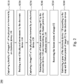
- FIG. 2 is a flow diagram illustrating a tracking method 200 according to an embodiment of this disclosure.
- the tracking method 200 can be utilized to build a three dimensional map of the physical environment, and calculate or estimate the pose of the electronic devices 110 and 120.
- the poses of the electronic devices 110 and 120 comprise the positions of the electronic devices 110 and 120 or the orientations of the electronic devices 110 and 120 or both.
- the tracking method 200 firstly executes step S210 to capture a plurality of images F1 of the physical environment over time by the electronic device 110.
- FIG. 3 is a schematic diagram illustrating views of the electronic devices 110 and 120 in the physical environment.
- the camera unit 111 of the electronic device 110 is configured to capture images F1 of the physical environment over time.
- the images F1 can be captured from different camera poses, and only one image is shown in Fig. 3 for simplicity.
- the tracking method 200 executes step S220 to build a three-dimensional map of the physical environment by the electronic device 110.
- the processor 112 is configured to extract the feature points from the images F1.
- FIG. 4A is a schematic diagram illustrating the feature points of the images F1 (only one image is shown therein for simplicity).
- the processor 112 is configured to extract the feature points F1P1, F1P2, F1P3, F1P4 and F1P5 of the object OBJ1 according to the images F1 captured by the camera unit 111.
- the feature points F1P1, F1P2, F1P3, F1P4 and F1P5 include descriptors and two dimensional (2D) coordinates of the feature points F1P1, F1P2, F1P3, F1P4 and F1P5 within the image F1.
- the descriptor of a feature point may indicate features such as a corner, a blob, an edge, a line, a texture, a color, etc.
- the feature points F1P1, F1P2, F1P3, F1P4 and F1P5 extracted from the image F1 also have the descriptors of the net texture and green color.
- the feature points are also called landmarks.
- FIG. 4B is a schematic diagram illustrating the map points in the three-dimensional map GM.
- the feature points F1P1, F1P2, F1P3, F1P4 and F1P5 are extracted by the processor 112, and the processor 112 is configured to create the map points MP1, MP2, MP3, MP4 and MP5 according to the feature points F1P1, F1P2, F1P3, F1P4 and F1P5 and add the map points MP1, MP2, MP3, MP4 and MP5 to the three-dimensional map GM.
- the map points MP1, MP2, MP3, MP4 and MP5 have data of the feature points F1P1, F1P2, F1P3, F1P4 and F1P5 (e.g. descriptors and 2D coordinates) and three dimensional (3D) coordinates.
- the descriptor of the feature point is also a descriptor of the corresponding map point indicating the feature(s) thereof.
- the 3D coordinates of the electronic device 110 is represented as P1(x, y, z), which at a certain time point (e.g. when the electronic device 110 powers on) can be set as an origin (0, 0, 0) of a coordinate system of the three-dimensional map (i.e.
- the coordinates of the map point MP1 are (x1, y1, z1)
- the coordinates of the map point MP2 are (x2, y2, z2)
- the coordinates of the map point MP3 are (x3, y3, z3)
- the coordinates of the map point MP4 are (x4, y4, z4)
- the coordinates of the map point MP5 are (x5, y5, z5).
- Take the map point MP1 for example to describe how to determine its coordinates (x1,y1,z1). It is assumed that the image F1 is captured when the electronic device 110 is at the origin.
- the values of x1 and y1 can be generated according to the 2D coordinates of the feature point F1P1.
- the value of z1 can be derived from the distance d1 between the map point MP1 and the electronic device 110, for example z1 may be equal to d1. This is how the values of x1, y1 and z1 are determined.
- the 3D coordinates of the map points MP2, MP3, MP4 and MP5 can also be determined.
- the distances d1, d2, d3, d4 and d5 may be obtained via a depth camera included in the camera unit 111 (not shown in figures).
- the depth camera can simultaneously capture an image for providing depth information of the feature points F1P1-F1P5, which can then be used to estimate the distances d1-d5.
- the distances d1, d2, d3, d4 and d5 may be calculated by the disparity.
- the disparity can be calculated based on displacement (e.g. the horizontal displacement) of the camera unit 111 in different time points. For example, in a time point, the camera unit 111 captures an image of X object and Y object, and in another time point, the camera unit 111 moves to another position (e.g. horizontal movement) and captures another image of X object and Y object again.
- first difference between two images of X object and a second difference between two images of Y object. If X object is closer to the camera unit 111 than Y object, then the first difference is larger than the second difference. Therefore, the distance between the camera unit 111 and X object and the distance between the camera unit 111 and Y object can be calculated. Thus, if X object comprises F1P1 and Y object comprises F1P2, the distances d1 and d2 can be calculated. The distances d3, d4 and d5 can also be calculated in such manner. In some embodiments, if the image F1 is captured when the electronic device 110 is at another pose (i.e.
- the 3D coordinates determined in above ways should be transformed so that they can be used as the 3D coordinates of the map points.
- This transformation reflects the movement from the origin to another pose, and will not be detailed here since it is a well-known technique.
- the tracking method 200 executes step S230 and S240 to capture an image F2 of the physical environment by the electronic device 120, extract a plurality of feature points of the image F2 by the electronic device 120 and transmit the extracted feature points to the electronic device 110.
- FIG. 5A is a schematic diagram illustrating the feature points of the image F2.
- the processor 122 is configured to extract the feature points F2P1 and F2P2 of the object OBJ1 and the feature points F2P3, F2P4, F2P5 and F2P6 of the object OBJ2 according to the image F2 captured by the camera unit 121.
- the communication unit 123 is configured to transmit the feature points F2P1, F2P2, F2P3, F2P4, F2P5 and F2P6 to the communication unit 113.
- the tracking method 200 executes step S250 to receive the feature points of image F2 by the communication unit 113 and step S260 to estimate a pose (i.e. position and/or orientation) of the electronic device 120 according to the three-dimensional map and the feature points of image F2 by the processor 112.
- a pose i.e. position and/or orientation
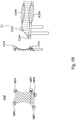
- FIG. 5B is a schematic diagram illustrating the mapping relationship between the feature points and the map points.
- the processor 112 when estimating the pose of the electronic device 120, the processor 112 first compare the received feature points F2P1, F2P2, F2P3, F2P4, F2P5, and F2P6 of the image F2 with the map points MP1, MP2, MP3, MP4, and MP5 in the map three-dimensional GM to determine if there is a match.
- the processor 112 performs a tracking algorithm to estimate the pose of the electronic device 120.
- the tracking algorithm is any applicable tracking algorithm which tracks the pose of an object by using the matched map points similar as mentioned below.
- the descriptors of the feature points F2P1 and F2P2 are a net texture with green color and corner
- the descriptors of the feature points F2P3 and F2P4 are a dot texture with brown and corner
- the descriptors of the feature points F2P5 and F2P6 are a dot texture with brown and line.
- the feature point F2P1 and the map point MP1 have the similar descriptors (i.e. net texture and corner). Therefore, the processor 112 would determine that the feature point F2P1 matches the map point MP1. For similar reason, the processor 112 would determine that the feature point F2P2 matches the map point MP5, because there are similar descriptors.
- the processor 112 matches the portion of the feature points F2P1 and F2P2 to the map points MP1 and MP5
- the portion of the feature points F2P1 and F2P2 are added to the map points MP1 and MP5 for updating or refining the three-dimensional map.
- the three-dimensional map GM will be updated continuously by the matching feature points extracted from the images captured by both the camera units 111 and 121.
- the map point MP1 includes two descriptors along with two timestamps.
- One of the descriptors is obtained along from the feature point F1P1 with a first timestamp (e.g., 2018041903040018) corresponding to the image F1.
- the other of the descriptors is obtained from the feature point F2P1 with a second timestamp (e.g., 2018041903040023) corresponding to the image F2.
- the first timestamp and the second timestamp are generated according to the time points when the images of F1P1 and F2P1 are captured, respectively.
- the descriptors of the map point in the three-dimensional map will be more precise and close to a current status of the physical environment.
- the descriptor of the feature point F2P1 may contain different feature(s) or even more features than that of the feature point F1P1, which reflects different statuses of the corresponding map point at different timestamps.
- the map point MP1 includes a specific amount of descriptors (e.g., N descriptors) along with latest N timestamps.
- N descriptors e.g., N timestamps
- the feature points F2P3, F2P4, F2P5 and F2P6 do not match to any map point, they can still be converted into the map points MP6, MP7, MP8, and MP9 as shown in FIG. 5C .
- the conversion method is similar to aforesaid embodiment shown in FIG. 4B .
- the camera unit 121 of the electronic device 120 comprises a depth camera
- the electronic device 120 can transmit to the electronic device 110 the feature points F2P3-F2P6 of the image F2 along with their depth information, which can be used to determine the distances between the feature points F2P3-F2P6 and the electronic device 120.
- the feature points F2P3-F2P6 can be converted into map points MP6-MP9 according to the determined distances, the 2D coordinates of the feature points F2P3-F2P6 and the corresponding pose of the electronic device 120 estimated in step S260.
- the feature points F2P3-F2P6 (including descriptors, 2D coordinates, timestamps, etc.) can be stored along with the corresponding pose of the electronic device 120 estimated in step S260 into the three-dimensional map GM, and wait to be converted into the map points MP6-MP9 later. More specifically, if later on the electronic device 110 obtains a feature point F4P1 in an image F4 (not shown in figures) matching one of the feature points (e.g.
- the feature points F2P3 can be converted into the map point MP6 according to the feature points F2P3 and F4P1 and their corresponding poses.
- the conversion method is well known and will not be detailed here.
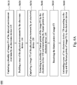
- FIG. 6A is a flow diagram illustrating a tracking method according to an embodiment of this disclosure.
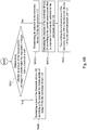
- FIG. 6B is a partial flow diagram of the FIG. 6A according to another embodiment of this disclosure.
- the steps S610 to S650 are similar to the steps S210 to S250. The difference is the image captured by the camera unit 121.
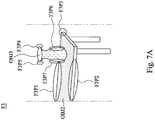
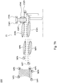
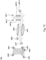
- FIG. 7A to 7C are a schematic diagram illustrating the feature points of the image F3.
- FIG. 7B is a schematic diagram illustrating the mapping relationship between the feature points and the map points.
- FIG. 7C is a schematic diagram illustrating the map points in the three-dimensional map GM.
- the processor 122 When the camera unit 121 captures the image F3 and transmits to the processor 122, the processor 122 is configured to extract the feature points F3P1, F3P2 and F3P3 of the object OBJ2 and the feature points F3P4, F3P5, F3P6 and F3P7 of the object OBJ3 according to the image F3.
- the communication unit 123 is configured to transmit the feature points F3P1, F3P2, F3P3, F3P4, F3P5, F3P6 and F3P7 to the communication unit 113.
- the processor 112 is configured to determine whether the feature points F3P1, F3P2, F3P3, F3P4, F3P5, F3P6, and F3P7 match any of the map points MP1-MP9.
- the descriptors of the feature points F3P1 and F3P2 are a dot texture with brown color and line
- the descriptors of the feature points F3P3 is a dot texture with brown color and corner
- the descriptors of the feature points F3P4 and F3P5 are a plus (i.e.
- the feature point F3P1 is determined to be matching the map point MP8, and the feature point F3P2 is determined to be matching to the map point MP9.
- the tracking method 600 further executes step S651 to determine whether an amount of the feature points of the image F3 which match the map points is larger than a threshold or not.
- step S651 the processor 112 matches the feature points F3P1 and F3P2 to the map points MP8 and MP9, the portion of the feature points F3P1 and F3P2 are added to the map points MP8 and MP9 for refining the map (e.g. adding the new descriptor and timestamp about the map points MP8 and MP9).
- step S651 the processor 112 calculates the amount of the feature points of the image F3 which match the map points.
- the amount of the feature points F3P1 and F3P2 of the image F3 which match the map points is two (i.e. F3P1 and F3P2). If the threshold is one, i.e. smaller than the amount of the matching feature points, then the processor 112 further executes step S660 to estimate the pose of the electronic device 120 according to the matched map points (i.e. MP8 and MP9).
- the value of threshold depends on the tracking algorithm used, and this disclosure is not limited to any specific tracking algorithm. Thus, here the threshold of one is just an example and the scope of this disclosure should not be limited thereto.
- the electronic device 110 further executes step S652A to transmit an indicator to the electronic device 120, which executes step S653A to estimate its own pose according to inertial measurement data in response to receiving the indicator from the electronic device 110.
- the indicator indicates a failure to estimate the pose of the electronic device 120, when the amount of the feature points of the image F3 which match the map points is not larger than the threshold.
- the indicator is used to tell the electronic device 120 to estimate its own pose by itself. Therefore, the processor 122 is configured to estimate the pose of the electronic device 120 according to the inertial measurement data.
- the inertial measurement data is generated by the IMU 124.
- the IMU 124 can provide further gesture or motion data of the electronic device 120, and the processor 122 can estimate the pose according to the data of the IMU 124.
- the electronic device 120 can still track its own pose even without the help of the more powerful electronic device 110.
- the tracking method 600 further executes step S654 to transmit the estimated pose of the electronic device 120 to the electronic device 110 by the communication unit 123.
- the electronic device 110 can still track the pose of the electronic device 120 when it fails to do the tracking by means of the feature points sent from the electronic device 120.
- the case of no enough matching feature points may occur when the quality of the image F3 is not good enough due to, for example, fast movement of the electronic device 120.
- the electronic device 120 can prevent the electronic device 120 from losing tracking, especially when the problem of image quality is temporary.
- the feature points F3P3, F3P4, F3P5, F3P6 and F3P7 fail in matching any of the map points MP1-MP9, they can still be converted into the map points MP10, MP11, MP12, MP13, and MP14 as shown in FIG. 7C .
- the conversion method is similar to aforesaid embodiment shown in FIG. 4B .
- the camera unit 121 of the electronic device 120 comprises a depth camera
- the electronic device 120 can transmit to the electronic device 110 the feature points F3P3-F3P7 of the image F3 along with their depth information, which can be used to determine the distances between the feature points F3P3-F3P7 and the electronic device 120.
- the feature points F3P3-F3P7 can be converted into map points MP10-MP14 according to the determined distances, the 2D coordinates of the feature points F3P3-F3P7 and the corresponding pose of the electronic device 120 estimated in step S660 or received from the electronic device 120 in step S654.
- the feature points F3P3-F3P7 (including descriptors, 2D coordinates, timestamps, etc.) can be stored into the three-dimensional map GM along with the corresponding pose of the electronic device 120 estimated in step S660 or received from the electronic device 120 in step S654, and wait to be converted into the map points MP10-MP14 later.
- the feature points F3P3 can be converted into the map point MP10 according to the feature points F3P3 and F5P1 and their corresponding poses.
- the conversion method is well known and will not be detailed here.
Landscapes
- Engineering & Computer Science (AREA)
- Physics & Mathematics (AREA)
- General Physics & Mathematics (AREA)
- Theoretical Computer Science (AREA)
- Computer Vision & Pattern Recognition (AREA)
- Multimedia (AREA)
- Image Analysis (AREA)
Claims (15)
- Un système de suivi, comprenant :un premier dispositif électronique (110) situé dans un environnement physique inconnu, le premier dispositif électronique (110) étant un visiocasque et comprenant :- une première unité de caméra (111) configurée pour la capture d'une pluralité de premières images de l'environnement physique inconnu ;- caractérisé par un premier processeur (112), couplé à la première unité de caméra (111) et configuré pour l'extraction d'une pluralité de premiers points caractéristiques à partir des premières images, la génération d'une pluralité de points de carte d'après les premiers points caractéristiques extraits, la construction d'une carte tridimensionnelle, 3D, de l'environnement physique inconnu d'après les points de carte, et l'obtention des distances (d1, d2, d3, d4, d5) entre la première unité de caméra (111) et des objets dans l'environnement physique inconnu représentés par la pluralité de premiers points caractéristiques de la pluralité de points de carte par une caméra de profondeur incluse dans la première unité de caméra (111), ou le calcul des distances (d1, d2, d3, d4, d5) entre la première unité de caméra (111) et les objets dans l'environnement physique inconnu représentés par la pluralité de premiers points caractéristiques de la pluralité de points de carte par disparité sur la base du déplacement de la première unité de caméra (111) à différents points temporels, les distances (d1, d2, d3, d4, d5) étant calculées par la disparité entre deux images capturées chacune par l'unité de caméra (111), la première image des deux images étant capturée à un point temporel, et la deuxième image des deux images étant capturée à un autre point temporel ultérieur lorsque l'unité de caméra (111) a été déplacée jusqu'à une autre position ; et- une première unité de communication (113) couplée au premier processeur (112) ; etun deuxième dispositif électronique (120) situé dans l'environnement physique inconnu, le deuxième dispositif électronique (120) étant un organe de commande, un téléphone intelligent, ou un visiocasque, et comprenant :- une deuxième unité de caméra (121) configurée pour la capture d'une deuxième image de l'environnement physique inconnu ;- un deuxième processeur (122) couplé à la deuxième unité de caméra (121) et configuré pour l'extraction d'une pluralité de deuxièmes points caractéristiques à partir de la deuxième image ;
le deuxième processeur (122) du deuxième dispositif électronique (120) étant équipé de moins de ressources de calcul que le premier processeur (112) du dispositif électronique (110) ;- une deuxième unité de communication (123) couplée au deuxième processeur (122) et configurée pour la transmission des deuxièmes points caractéristiques au premier dispositif électronique (110) ;dans lequel la première unité de communication (113) est configurée pour la réception des deuxièmes points caractéristiques, et le premier processeur (112) est en outre configuré pour l'estimation d'une pose du deuxième dispositif électronique (120) d'après la carte 3D et les deuxièmes points caractéristiques reçus ;dans lequel la pose du deuxième dispositif électronique (120) comprend au moins soit une position du deuxième dispositif électronique (120) dans la carte 3D soit une orientation du deuxième dispositif électronique (120) dans la carte 3D. - Le système de suivi de la revendication 1, dans lequel la première unité de communication (113) transmet la pose estimée du deuxième dispositif électronique (120) au deuxième dispositif électronique (120).
- Le système de suivi de la revendication 1, dans lequel le premier processeur (112) estime la pose du deuxième dispositif électronique (120) lorsqu'une quantité des deuxièmes points caractéristiques qui coïncident avec les points de carte est supérieure à un seuil.
- Le système de suivi de la revendication 3, dans lequel le premier processeur (112) estime la pose du deuxième dispositif électronique (120) d'après les points de carte qui sont mis en coïncidence avec les deuxièmes points caractéristiques.
- Le système de suivi de la revendication 3, dans lequel chacun des points de carte comprend un premier descripteur qui indique au moins une caractéristique du point de carte correspondant, et chacun des deuxièmes points caractéristiques comprend un deuxième descripteur qui indique au moins une caractéristique du deuxième point caractéristique correspondant, dans lequel le premier processeur (112) est configuré pour déterminer s'il existe une coïncidence entre le deuxième point caractéristique et le point de carte d'après les premiers et deuxièmes descripteurs.
- Le système de suivi de la revendication 5, dans lequel le deuxième point caractéristique comprend en outre une estampille temporelle correspondant au deuxième descripteur, et le premier processeur (112) met à jour la carte 3D en ajoutant à un premier point de carte des points de carte le descripteur et l'estampille temporelle du deuxième point caractéristique qui coïncide avec le premier point de carte.
- Le système de suivi de la revendication 1, dans lequel le premier dispositif électronique (110) transmet au deuxième dispositif électronique (120) un indicateur indiquant un échec à estimer la pose du deuxième dispositif électronique (120), lorsqu'une quantité des deuxièmes points caractéristiques qui coïncident avec les points de carte n'est pas supérieure à un seuil.
- Le système de suivi de la revendication 7, dans lequel le deuxième dispositif électronique (120) comprend en outre une unité de mesure inertielle, IMU, pour la génération de données de mesure inertielle, et le deuxième processeur (122) est configuré pour l'estimation de la pose du deuxième dispositif électronique (120) d'après les données de mesure inertielle en réponse à la réception de l'indicateur.
- Le système de suivi de la revendication 8, dans lequel le deuxième dispositif électronique (120) transmet la position estimée du deuxième dispositif électronique (120) au premier dispositif électronique (110).
- Le système de suivi de la revendication 9, dans lequel le premier processeur (112) met à jour la carte 3D en ajoutant la pose estimée reçue du deuxième dispositif électronique (120) et le deuxième point caractéristique qui ne coïncident avec aucun des points de carte à la carte 3D.
- Un procédé de suivi, comprenant :la capture d'une pluralité de premières images d'un environnement physique inconnu par un premier dispositif électronique (110), le premier dispositif électronique (110) étant un visiocasque ;caractérisé par l'extraction d'une pluralité de premiers points caractéristiques à partir des premières images, la génération d'une pluralité de points de carte d'après les premiers points caractéristiques extraits, la construction d'une carte tridimensionnelle, 3D, de l'environnement physique inconnu d'après les points de carte par le premier dispositif électronique (110), et l'obtention des distances (d1, d2, d3, d4, d5) entre la première unité de caméra (111) et des objets dans l'environnement physique inconnu représentés par la pluralité de premiers points caractéristiques de la pluralité de points de carte par une caméra de profondeur incluse dans la première unité de caméra (111), ou le calcul des distances (d1, d2, d3, d4, d5) entre la première unité de caméra (111) et les objets dans l'environnement physique inconnu représentés par la pluralité de premiers points caractéristiques de la pluralité de points de carte par disparité sur la base du déplacement de la première unité de caméra (111) à différents points temporels, les distances (d1, d2, d3, d4, d5) étant calculées par la disparité entre deux images capturées chacune par l'unité de caméra (111), la première image des deux images étant capturée à un point temporel, et la deuxième image des deux images étant capturée à un autre point temporel ultérieur lorsque l'unité de caméra (111) a été déplacée jusqu'à une autre position ;la capture d'une deuxième image de l'environnement physique par un deuxième dispositif électronique (120), le deuxième dispositif électronique (120) étant un organe de commande, un téléphone intelligent, ou un visiocasque ;l'extraction d'une pluralité de deuxièmes points caractéristiques à partir de la deuxième image et la transmission des deuxièmes points caractéristiques au premier dispositif électronique (110) par le deuxième dispositif électronique (120) ;
dans lequel le deuxième processeur (122) du deuxième dispositif électronique (120) est équipé de moins de ressources de calcul que le premier processeur (112) du dispositif électronique (110) ;la réception de deuxièmes points caractéristiques et l'estimation d'une pose du deuxième dispositif électronique (120) d'après la carte 3D et les deuxièmes points caractéristiques reçus par le premier dispositif électronique ; et
dans lequel la pose du deuxième dispositif électronique (120) comprend au moins soit une position du deuxième dispositif électronique dans la carte 3D soit une orientation du deuxième dispositif électronique (120) dans la carte 3D. - Le système de suivi de la revendication 1, dans lequel le premier processeur (112) est en outre configuré pour la comparaison des deuxièmes points caractéristiques avec les points de carte de sorte à déterminer s'il existe une coïncidence entre ceux-ci et pour la mise à jour de la carte 3D d'après le résultat de la comparaison.
- Le système de suivi de la revendication 12, dans lequel chacun des points de carte comprend un premier descripteur qui indique au moins une caractéristique du point de carte correspondant, et chacun des deuxièmes points caractéristiques comprend un deuxième descripteur qui indique au moins une caractéristique du deuxième point caractéristique correspondant, dans lequel le premier processeur (112) est configuré pour déterminer s'il existe une coïncidence entre le deuxième point caractéristique et le point de carte d'après les premier et deuxième descripteurs.
- Le système de suivi de la revendication 13, dans lequel le deuxième point caractéristique comprend en outre une estampille temporelle correspondant au deuxième descripteur, et le premier processeur (112) met à jour la carte 3D en ajoutant à un premier point de carte des points de carte le descripteur et l'estampille temporelle du deuxième point caractéristique qui coïncide avec le premier point de carte.
- Le système de suivi de la revendication 12, dans lequel le premier processeur (112) estime une pose du deuxième dispositif électronique (120) d'après les points de carte qui sont mis en coïncidence avec les deuxièmes points caractéristiques, et met à jour la carte 3D en ajoutant à la carte 3D la pose estimée du deuxième dispositif électronique (120) et le deuxième point caractéristique qui ne coïncident avec aucun des points de carte.
Applications Claiming Priority (1)
| Application Number | Priority Date | Filing Date | Title |
|---|---|---|---|
| US201762491269P | 2017-04-28 | 2017-04-28 |
Publications (2)
| Publication Number | Publication Date |
|---|---|
| EP3396594A1 EP3396594A1 (fr) | 2018-10-31 |
| EP3396594B1 true EP3396594B1 (fr) | 2021-04-07 |
Family
ID=62196316
Family Applications (1)
| Application Number | Title | Priority Date | Filing Date |
|---|---|---|---|
| EP18170053.5A Active EP3396594B1 (fr) | 2017-04-28 | 2018-04-30 | Système de suivi et procédé associé |
Country Status (1)
| Country | Link |
|---|---|
| EP (1) | EP3396594B1 (fr) |
Families Citing this family (1)
| Publication number | Priority date | Publication date | Assignee | Title |
|---|---|---|---|---|
| CN110456927B (zh) * | 2019-08-13 | 2021-07-16 | 腾讯科技(深圳)有限公司 | 设备间的操作映射方法、装置及计算机设备 |
Family Cites Families (1)
| Publication number | Priority date | Publication date | Assignee | Title |
|---|---|---|---|---|
| US8531519B1 (en) * | 2012-09-06 | 2013-09-10 | Google Inc. | Automatic multi-device localization and collaboration using cameras |
-
2018
- 2018-04-30 EP EP18170053.5A patent/EP3396594B1/fr active Active
Non-Patent Citations (2)
| Title |
|---|
| GUERRA E ET AL: "Collaborative localization for autonomous robots in structured environments", 2016 IEEE 14TH INTERNATIONAL CONFERENCE ON INDUSTRIAL INFORMATICS (INDIN), IEEE, 19 July 2016 (2016-07-19), pages 219 - 224, XP033043909, DOI: 10.1109/INDIN.2016.7819162 * |
| JARAMILLO CARLOS ET AL: "6-DoF pose localization in 3D point-cloud dense maps using a monocular camera", 2013 IEEE INTERNATIONAL CONFERENCE ON ROBOTICS AND BIOMIMETICS (ROBIO), IEEE, 12 December 2013 (2013-12-12), pages 1747 - 1752, XP032579621, DOI: 10.1109/ROBIO.2013.6739720 * |
Also Published As
| Publication number | Publication date |
|---|---|
| EP3396594A1 (fr) | 2018-10-31 |
Similar Documents
| Publication | Publication Date | Title |
|---|---|---|
| US10600206B2 (en) | Tracking system and method thereof | |
| US12062210B2 (en) | Data processing method and apparatus | |
| CN109084746B (zh) | 用于具有辅助传感器的自主平台引导系统的单目模式 | |
| US12175748B2 (en) | System and method for spatially mapping smart objects within augmented reality scenes | |
| US11347238B2 (en) | System and method for probabilistic multi-robot SLAM | |
| EP3400507B1 (fr) | Système et procédé de détection et de rétablissement de défaillances pour une odométrie et une cartographie simultanées | |
| CN113874870A (zh) | 基于图像的定位 | |
| EP3907974B1 (fr) | Dispositif d'extrémité, système de communication à trois parties comprenant un serveur en nuage et un serveur périphérique pour commander un dispositif d'extrémité et son procédé de fonctionnement | |
| US11331801B2 (en) | System and method for probabilistic multi-robot positioning | |
| US20220414919A1 (en) | Method and apparatus for depth-aided visual inertial odometry | |
| Hashemifar et al. | Augmenting visual SLAM with Wi-Fi sensing for indoor applications | |
| CN106708048A (zh) | 机器人的天花板图像定位方法和系统 | |
| CN114485640A (zh) | 基于点线特征的单目视觉惯性同步定位与建图方法及系统 | |
| CN113432595A (zh) | 设备状态获取方法、装置、计算机设备及存储介质 | |
| EP4181066B1 (fr) | Procédé et appareil d'estimation de pose | |
| EP3396594A1 (fr) | Système de suivi et procédé associé | |
| US11448511B2 (en) | System and method for probabilistic multi-robot positioning | |
| WO2024057779A1 (fr) | Dispositif de traitement d'informations, programme, et système de traitement d'informations | |
| JP2023081005A (ja) | 情報処理装置、情報処理方法およびプログラム | |
| CN120411205A (zh) | 目标定位方法、存储介质、程序产品、电子设备及车辆 | |
| US20260134566A1 (en) | Information processing apparatus, information processing method, and storage medium | |
| EP4459229A1 (fr) | Procédé d'alignement de données, système multi-dispositifs et support d'informations non transitoire lisible par ordinateur | |
| JP2024062512A (ja) | 情報処理装置、移動デバイス、システム、制御方法、及びプログラム | |
| CN116698023A (zh) | 状态区分方法、装置、设备及存储介质 | |
| HK40061179A (en) | Image-based localization |
Legal Events
| Date | Code | Title | Description |
|---|---|---|---|
| PUAI | Public reference made under article 153(3) epc to a published international application that has entered the european phase |
Free format text: ORIGINAL CODE: 0009012 |
|
| STAA | Information on the status of an ep patent application or granted ep patent |
Free format text: STATUS: REQUEST FOR EXAMINATION WAS MADE |
|
| 17P | Request for examination filed |
Effective date: 20180430 |
|
| AK | Designated contracting states |
Kind code of ref document: A1 Designated state(s): AL AT BE BG CH CY CZ DE DK EE ES FI FR GB GR HR HU IE IS IT LI LT LU LV MC MK MT NL NO PL PT RO RS SE SI SK SM TR |
|
| AX | Request for extension of the european patent |
Extension state: BA ME |
|
| RBV | Designated contracting states (corrected) |
Designated state(s): AL AT BE BG CH CY CZ DE DK EE ES FI FR GB GR HR HU IE IS IT LI LT LU LV MC MK MT NL NO PL PT RO RS SE SI SK SM TR |
|
| STAA | Information on the status of an ep patent application or granted ep patent |
Free format text: STATUS: EXAMINATION IS IN PROGRESS |
|
| 17Q | First examination report despatched |
Effective date: 20190708 |
|
| REG | Reference to a national code |
Ref country code: DE Ref legal event code: R079 Ref document number: 602018014989 Country of ref document: DE Free format text: PREVIOUS MAIN CLASS: G06K0009000000 Ipc: G06K0009200000 |
|
| RIC1 | Information provided on ipc code assigned before grant |
Ipc: G06K 9/20 20060101AFI20200930BHEP Ipc: G06K 9/46 20060101ALI20200930BHEP Ipc: G06T 7/73 20170101ALI20200930BHEP |
|
| GRAP | Despatch of communication of intention to grant a patent |
Free format text: ORIGINAL CODE: EPIDOSNIGR1 |
|
| STAA | Information on the status of an ep patent application or granted ep patent |
Free format text: STATUS: GRANT OF PATENT IS INTENDED |
|
| INTG | Intention to grant announced |
Effective date: 20201116 |
|
| GRAS | Grant fee paid |
Free format text: ORIGINAL CODE: EPIDOSNIGR3 |
|
| GRAA | (expected) grant |
Free format text: ORIGINAL CODE: 0009210 |
|
| STAA | Information on the status of an ep patent application or granted ep patent |
Free format text: STATUS: THE PATENT HAS BEEN GRANTED |
|
| AK | Designated contracting states |
Kind code of ref document: B1 Designated state(s): AL AT BE BG CH CY CZ DE DK EE ES FI FR GB GR HR HU IE IS IT LI LT LU LV MC MK MT NL NO PL PT RO RS SE SI SK SM TR |
|
| REG | Reference to a national code |
Ref country code: GB Ref legal event code: FG4D |
|
| REG | Reference to a national code |
Ref country code: CH Ref legal event code: EP Ref country code: AT Ref legal event code: REF Ref document number: 1380655 Country of ref document: AT Kind code of ref document: T Effective date: 20210415 |
|
| REG | Reference to a national code |
Ref country code: DE Ref legal event code: R096 Ref document number: 602018014989 Country of ref document: DE |
|
| REG | Reference to a national code |
Ref country code: IE Ref legal event code: FG4D |
|
| REG | Reference to a national code |
Ref country code: NL Ref legal event code: FP |
|
| REG | Reference to a national code |
Ref country code: LT Ref legal event code: MG9D |
|
| REG | Reference to a national code |
Ref country code: AT Ref legal event code: MK05 Ref document number: 1380655 Country of ref document: AT Kind code of ref document: T Effective date: 20210407 |
|
| PG25 | Lapsed in a contracting state [announced via postgrant information from national office to epo] |
Ref country code: AT Free format text: LAPSE BECAUSE OF FAILURE TO SUBMIT A TRANSLATION OF THE DESCRIPTION OR TO PAY THE FEE WITHIN THE PRESCRIBED TIME-LIMIT Effective date: 20210407 Ref country code: BG Free format text: LAPSE BECAUSE OF FAILURE TO SUBMIT A TRANSLATION OF THE DESCRIPTION OR TO PAY THE FEE WITHIN THE PRESCRIBED TIME-LIMIT Effective date: 20210707 Ref country code: FI Free format text: LAPSE BECAUSE OF FAILURE TO SUBMIT A TRANSLATION OF THE DESCRIPTION OR TO PAY THE FEE WITHIN THE PRESCRIBED TIME-LIMIT Effective date: 20210407 Ref country code: LT Free format text: LAPSE BECAUSE OF FAILURE TO SUBMIT A TRANSLATION OF THE DESCRIPTION OR TO PAY THE FEE WITHIN THE PRESCRIBED TIME-LIMIT Effective date: 20210407 Ref country code: HR Free format text: LAPSE BECAUSE OF FAILURE TO SUBMIT A TRANSLATION OF THE DESCRIPTION OR TO PAY THE FEE WITHIN THE PRESCRIBED TIME-LIMIT Effective date: 20210407 |
|
| REG | Reference to a national code |
Ref country code: DE Ref legal event code: R079 Ref document number: 602018014989 Country of ref document: DE Free format text: PREVIOUS MAIN CLASS: G06K0009200000 Ipc: G06V0030140000 |
|
| PG25 | Lapsed in a contracting state [announced via postgrant information from national office to epo] |
Ref country code: NO Free format text: LAPSE BECAUSE OF FAILURE TO SUBMIT A TRANSLATION OF THE DESCRIPTION OR TO PAY THE FEE WITHIN THE PRESCRIBED TIME-LIMIT Effective date: 20210707 Ref country code: PT Free format text: LAPSE BECAUSE OF FAILURE TO SUBMIT A TRANSLATION OF THE DESCRIPTION OR TO PAY THE FEE WITHIN THE PRESCRIBED TIME-LIMIT Effective date: 20210809 Ref country code: LV Free format text: LAPSE BECAUSE OF FAILURE TO SUBMIT A TRANSLATION OF THE DESCRIPTION OR TO PAY THE FEE WITHIN THE PRESCRIBED TIME-LIMIT Effective date: 20210407 Ref country code: PL Free format text: LAPSE BECAUSE OF FAILURE TO SUBMIT A TRANSLATION OF THE DESCRIPTION OR TO PAY THE FEE WITHIN THE PRESCRIBED TIME-LIMIT Effective date: 20210407 Ref country code: SE Free format text: LAPSE BECAUSE OF FAILURE TO SUBMIT A TRANSLATION OF THE DESCRIPTION OR TO PAY THE FEE WITHIN THE PRESCRIBED TIME-LIMIT Effective date: 20210407 Ref country code: RS Free format text: LAPSE BECAUSE OF FAILURE TO SUBMIT A TRANSLATION OF THE DESCRIPTION OR TO PAY THE FEE WITHIN THE PRESCRIBED TIME-LIMIT Effective date: 20210407 Ref country code: IS Free format text: LAPSE BECAUSE OF FAILURE TO SUBMIT A TRANSLATION OF THE DESCRIPTION OR TO PAY THE FEE WITHIN THE PRESCRIBED TIME-LIMIT Effective date: 20210807 Ref country code: GR Free format text: LAPSE BECAUSE OF FAILURE TO SUBMIT A TRANSLATION OF THE DESCRIPTION OR TO PAY THE FEE WITHIN THE PRESCRIBED TIME-LIMIT Effective date: 20210708 |
|
| PG25 | Lapsed in a contracting state [announced via postgrant information from national office to epo] |
Ref country code: LU Free format text: LAPSE BECAUSE OF NON-PAYMENT OF DUE FEES Effective date: 20210430 |
|
| REG | Reference to a national code |
Ref country code: DE Ref legal event code: R097 Ref document number: 602018014989 Country of ref document: DE |
|
| REG | Reference to a national code |
Ref country code: BE Ref legal event code: MM Effective date: 20210430 |
|
| PG25 | Lapsed in a contracting state [announced via postgrant information from national office to epo] |
Ref country code: SK Free format text: LAPSE BECAUSE OF FAILURE TO SUBMIT A TRANSLATION OF THE DESCRIPTION OR TO PAY THE FEE WITHIN THE PRESCRIBED TIME-LIMIT Effective date: 20210407 Ref country code: SM Free format text: LAPSE BECAUSE OF FAILURE TO SUBMIT A TRANSLATION OF THE DESCRIPTION OR TO PAY THE FEE WITHIN THE PRESCRIBED TIME-LIMIT Effective date: 20210407 Ref country code: ES Free format text: LAPSE BECAUSE OF FAILURE TO SUBMIT A TRANSLATION OF THE DESCRIPTION OR TO PAY THE FEE WITHIN THE PRESCRIBED TIME-LIMIT Effective date: 20210407 Ref country code: EE Free format text: LAPSE BECAUSE OF FAILURE TO SUBMIT A TRANSLATION OF THE DESCRIPTION OR TO PAY THE FEE WITHIN THE PRESCRIBED TIME-LIMIT Effective date: 20210407 Ref country code: RO Free format text: LAPSE BECAUSE OF FAILURE TO SUBMIT A TRANSLATION OF THE DESCRIPTION OR TO PAY THE FEE WITHIN THE PRESCRIBED TIME-LIMIT Effective date: 20210407 Ref country code: CH Free format text: LAPSE BECAUSE OF NON-PAYMENT OF DUE FEES Effective date: 20210430 Ref country code: CZ Free format text: LAPSE BECAUSE OF FAILURE TO SUBMIT A TRANSLATION OF THE DESCRIPTION OR TO PAY THE FEE WITHIN THE PRESCRIBED TIME-LIMIT Effective date: 20210407 Ref country code: DK Free format text: LAPSE BECAUSE OF FAILURE TO SUBMIT A TRANSLATION OF THE DESCRIPTION OR TO PAY THE FEE WITHIN THE PRESCRIBED TIME-LIMIT Effective date: 20210407 Ref country code: LI Free format text: LAPSE BECAUSE OF NON-PAYMENT OF DUE FEES Effective date: 20210430 Ref country code: MC Free format text: LAPSE BECAUSE OF FAILURE TO SUBMIT A TRANSLATION OF THE DESCRIPTION OR TO PAY THE FEE WITHIN THE PRESCRIBED TIME-LIMIT Effective date: 20210407 |
|
| PLBE | No opposition filed within time limit |
Free format text: ORIGINAL CODE: 0009261 |
|
| STAA | Information on the status of an ep patent application or granted ep patent |
Free format text: STATUS: NO OPPOSITION FILED WITHIN TIME LIMIT |
|
| 26N | No opposition filed |
Effective date: 20220110 |
|
| PG25 | Lapsed in a contracting state [announced via postgrant information from national office to epo] |
Ref country code: IE Free format text: LAPSE BECAUSE OF NON-PAYMENT OF DUE FEES Effective date: 20210430 |
|
| PG25 | Lapsed in a contracting state [announced via postgrant information from national office to epo] |
Ref country code: IS Free format text: LAPSE BECAUSE OF FAILURE TO SUBMIT A TRANSLATION OF THE DESCRIPTION OR TO PAY THE FEE WITHIN THE PRESCRIBED TIME-LIMIT Effective date: 20210807 Ref country code: AL Free format text: LAPSE BECAUSE OF FAILURE TO SUBMIT A TRANSLATION OF THE DESCRIPTION OR TO PAY THE FEE WITHIN THE PRESCRIBED TIME-LIMIT Effective date: 20210407 |
|
| PG25 | Lapsed in a contracting state [announced via postgrant information from national office to epo] |
Ref country code: IT Free format text: LAPSE BECAUSE OF FAILURE TO SUBMIT A TRANSLATION OF THE DESCRIPTION OR TO PAY THE FEE WITHIN THE PRESCRIBED TIME-LIMIT Effective date: 20210407 Ref country code: BE Free format text: LAPSE BECAUSE OF NON-PAYMENT OF DUE FEES Effective date: 20210430 |
|
| REG | Reference to a national code |
Ref country code: DE Ref legal event code: R082 Ref document number: 602018014989 Country of ref document: DE Representative=s name: WAGNER & GEYER PARTNERSCHAFT MBB PATENT- UND R, DE |
|
| PG25 | Lapsed in a contracting state [announced via postgrant information from national office to epo] |
Ref country code: CY Free format text: LAPSE BECAUSE OF FAILURE TO SUBMIT A TRANSLATION OF THE DESCRIPTION OR TO PAY THE FEE WITHIN THE PRESCRIBED TIME-LIMIT Effective date: 20210407 |
|
| P01 | Opt-out of the competence of the unified patent court (upc) registered |
Effective date: 20230602 |
|
| PG25 | Lapsed in a contracting state [announced via postgrant information from national office to epo] |
Ref country code: HU Free format text: LAPSE BECAUSE OF FAILURE TO SUBMIT A TRANSLATION OF THE DESCRIPTION OR TO PAY THE FEE WITHIN THE PRESCRIBED TIME-LIMIT; INVALID AB INITIO Effective date: 20180430 |
|
| PG25 | Lapsed in a contracting state [announced via postgrant information from national office to epo] |
Ref country code: MK Free format text: LAPSE BECAUSE OF FAILURE TO SUBMIT A TRANSLATION OF THE DESCRIPTION OR TO PAY THE FEE WITHIN THE PRESCRIBED TIME-LIMIT Effective date: 20210407 |
|
| PG25 | Lapsed in a contracting state [announced via postgrant information from national office to epo] |
Ref country code: TR Free format text: LAPSE BECAUSE OF FAILURE TO SUBMIT A TRANSLATION OF THE DESCRIPTION OR TO PAY THE FEE WITHIN THE PRESCRIBED TIME-LIMIT Effective date: 20210407 |
|
| PG25 | Lapsed in a contracting state [announced via postgrant information from national office to epo] |
Ref country code: MT Free format text: LAPSE BECAUSE OF FAILURE TO SUBMIT A TRANSLATION OF THE DESCRIPTION OR TO PAY THE FEE WITHIN THE PRESCRIBED TIME-LIMIT Effective date: 20210407 |
|
| PGFP | Annual fee paid to national office [announced via postgrant information from national office to epo] |
Ref country code: NL Payment date: 20250317 Year of fee payment: 8 |
|
| PGFP | Annual fee paid to national office [announced via postgrant information from national office to epo] |
Ref country code: FR Payment date: 20250310 Year of fee payment: 8 |
|
| PGFP | Annual fee paid to national office [announced via postgrant information from national office to epo] |
Ref country code: GB Payment date: 20250306 Year of fee payment: 8 |
|
| PGFP | Annual fee paid to national office [announced via postgrant information from national office to epo] |
Ref country code: DE Payment date: 20250305 Year of fee payment: 8 |