EP3396444B1 - Vorrichtung zur erzeugung eines polarisierten lichtstrahls, bilderzeugungsvorrichtung und head-up-display - Google Patents
Vorrichtung zur erzeugung eines polarisierten lichtstrahls, bilderzeugungsvorrichtung und head-up-display Download PDFInfo
- Publication number
- EP3396444B1 EP3396444B1 EP18169367.2A EP18169367A EP3396444B1 EP 3396444 B1 EP3396444 B1 EP 3396444B1 EP 18169367 A EP18169367 A EP 18169367A EP 3396444 B1 EP3396444 B1 EP 3396444B1
- Authority
- EP
- European Patent Office
- Prior art keywords
- light
- filter
- light source
- reflector
- reflect
- Prior art date
- Legal status (The legal status is an assumption and is not a legal conclusion. Google has not performed a legal analysis and makes no representation as to the accuracy of the status listed.)
- Active
Links
Images
Classifications
-
- G—PHYSICS
- G02—OPTICS
- G02B—OPTICAL ELEMENTS, SYSTEMS OR APPARATUS
- G02B19/00—Condensers, e.g. light collectors or similar non-imaging optics
- G02B19/0004—Condensers, e.g. light collectors or similar non-imaging optics characterised by the optical means employed
- G02B19/0019—Condensers, e.g. light collectors or similar non-imaging optics characterised by the optical means employed having reflective surfaces only (e.g. louvre systems, systems with multiple planar reflectors)
- G02B19/0023—Condensers, e.g. light collectors or similar non-imaging optics characterised by the optical means employed having reflective surfaces only (e.g. louvre systems, systems with multiple planar reflectors) at least one surface having optical power
-
- G—PHYSICS
- G02—OPTICS
- G02B—OPTICAL ELEMENTS, SYSTEMS OR APPARATUS
- G02B27/00—Optical systems or apparatus not provided for by any of the groups G02B1/00 - G02B26/00, G02B30/00
- G02B27/28—Optical systems or apparatus not provided for by any of the groups G02B1/00 - G02B26/00, G02B30/00 for polarising
- G02B27/283—Optical systems or apparatus not provided for by any of the groups G02B1/00 - G02B26/00, G02B30/00 for polarising used for beam splitting or combining
- G02B27/285—Optical systems or apparatus not provided for by any of the groups G02B1/00 - G02B26/00, G02B30/00 for polarising used for beam splitting or combining comprising arrays of elements, e.g. microprisms
-
- G—PHYSICS
- G02—OPTICS
- G02B—OPTICAL ELEMENTS, SYSTEMS OR APPARATUS
- G02B27/00—Optical systems or apparatus not provided for by any of the groups G02B1/00 - G02B26/00, G02B30/00
- G02B27/28—Optical systems or apparatus not provided for by any of the groups G02B1/00 - G02B26/00, G02B30/00 for polarising
- G02B27/286—Optical systems or apparatus not provided for by any of the groups G02B1/00 - G02B26/00, G02B30/00 for polarising for controlling or changing the state of polarisation, e.g. transforming one polarisation state into another
-
- G—PHYSICS
- G02—OPTICS
- G02F—OPTICAL DEVICES OR ARRANGEMENTS FOR THE CONTROL OF LIGHT BY MODIFICATION OF THE OPTICAL PROPERTIES OF THE MEDIA OF THE ELEMENTS INVOLVED THEREIN; NON-LINEAR OPTICS; FREQUENCY-CHANGING OF LIGHT; OPTICAL LOGIC ELEMENTS; OPTICAL ANALOGUE/DIGITAL CONVERTERS
- G02F1/00—Devices or arrangements for the control of the intensity, colour, phase, polarisation or direction of light arriving from an independent light source, e.g. switching, gating or modulating; Non-linear optics
- G02F1/01—Devices or arrangements for the control of the intensity, colour, phase, polarisation or direction of light arriving from an independent light source, e.g. switching, gating or modulating; Non-linear optics for the control of the intensity, phase, polarisation or colour
- G02F1/13—Devices or arrangements for the control of the intensity, colour, phase, polarisation or direction of light arriving from an independent light source, e.g. switching, gating or modulating; Non-linear optics for the control of the intensity, phase, polarisation or colour based on liquid crystals, e.g. single liquid crystal display cells
- G02F1/133—Constructional arrangements; Operation of liquid crystal cells; Circuit arrangements
- G02F1/1333—Constructional arrangements; Manufacturing methods
- G02F1/1335—Structural association of cells with optical devices, e.g. polarisers or reflectors
- G02F1/1336—Illuminating devices
- G02F1/133602—Direct backlight
- G02F1/133605—Direct backlight including specially adapted reflectors
-
- G—PHYSICS
- G02—OPTICS
- G02F—OPTICAL DEVICES OR ARRANGEMENTS FOR THE CONTROL OF LIGHT BY MODIFICATION OF THE OPTICAL PROPERTIES OF THE MEDIA OF THE ELEMENTS INVOLVED THEREIN; NON-LINEAR OPTICS; FREQUENCY-CHANGING OF LIGHT; OPTICAL LOGIC ELEMENTS; OPTICAL ANALOGUE/DIGITAL CONVERTERS
- G02F1/00—Devices or arrangements for the control of the intensity, colour, phase, polarisation or direction of light arriving from an independent light source, e.g. switching, gating or modulating; Non-linear optics
- G02F1/01—Devices or arrangements for the control of the intensity, colour, phase, polarisation or direction of light arriving from an independent light source, e.g. switching, gating or modulating; Non-linear optics for the control of the intensity, phase, polarisation or colour
- G02F1/13—Devices or arrangements for the control of the intensity, colour, phase, polarisation or direction of light arriving from an independent light source, e.g. switching, gating or modulating; Non-linear optics for the control of the intensity, phase, polarisation or colour based on liquid crystals, e.g. single liquid crystal display cells
- G02F1/133—Constructional arrangements; Operation of liquid crystal cells; Circuit arrangements
- G02F1/1333—Constructional arrangements; Manufacturing methods
- G02F1/1335—Structural association of cells with optical devices, e.g. polarisers or reflectors
- G02F1/1336—Illuminating devices
- G02F1/13362—Illuminating devices providing polarized light, e.g. by converting a polarisation component into another one
Definitions
- the present invention relates to display systems.
- It relates more particularly to a device for producing a polarized light beam, an image generating device and a head-up display.
- the invention applies particularly advantageously in the case where it is desired to use a device for producing a polarized light beam to illuminate a screen with a high light intensity, while limiting the heating of the device for producing the light beam. .
- a device for producing a polarized light beam comprising a light source, a reflector and a filter illuminated by the light source and designed to transmit a first polarization of the light and to reflect a second polarization of light.
- the light transmitted by the filter thus has the first polarization and can therefore be used to backlight a screen, typically a liquid crystal screen comprising an input polarizer whose axis corresponds to this first polarization.
- the light reflected by the filter (which has the second polarization) is on the other hand returned towards the interior of the device, typically towards the reflector where it can be reflected again with modification of its polarization, so that this light can (at least in part) then be transmitted through the filter in the direction of the screen.
- the present invention proposes a device for production of a light beam according to claim 1, in which the reflector comprises at the level of the flared shape at least a first surface portion designed to reflect, in the direction of the filter, light rays received (directly) from the light source and at least one second surface portion designed to reflect, in the direction of the filter, light rays received from the filter after reflection by the filter.
- part of the surface of the reflector (second portion) is not used to reflect towards the filter the light received from the light source; this part of the surface of the reflector therefore does not participate in the heating of the light source mentioned above, but nevertheless retains an optical role since it makes it possible to send light back to the filter (by modifying its polarization).
- the invention also proposes an image generation device comprising a device for producing a light beam as proposed above and a screen arranged to receive said light beam.
- Such a screen such as a liquid crystal screen, for example comprises an input polarizer designed to transmit the first polarization.
- the invention finally proposes a head-up display comprising an image generation device as has just been indicated and an image projection device adapted to transmit in the direction of a partially transparent blade the images generated by the image generation.
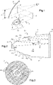
- FIG. 1 the main elements of a head-up display 1 intended to equip a vehicle, for example a motor vehicle, have been schematically represented.
- Such a display 1 is suitable for creating a virtual image I in the field of vision of a driver of the vehicle, so that the driver can see this virtual image I and any information it contains without having to look away.
- the display 1 comprises a partially transparent blade 2 (also called “semi-transparent blade” ) placed in the driver's field of vision, an image generation device 3 adapted to generate images and a projection 4 of images adapted to return, in the direction of said partially transparent blade 2, the images generated by the device of image generation 3.
- a partially transparent blade 2 also called “semi-transparent blade”
- an image generation device 3 adapted to generate images
- a projection 4 of images adapted to return, in the direction of said partially transparent blade 2, the images generated by the device of image generation 3.
- the partially transparent blade 2 is here a combiner 2, that is to say a partially transparent blade dedicated to the head-up display 1.
- Such a combiner 2 is here placed between the windshield 9 of the vehicle and the eyes of the driver.
- the partially transparent blade could be confused with the windshield of the vehicle.
- it is the windscreen of the vehicle which has the function of partially transparent blade for the head-up display.
- the image projection device comprises a folding mirror 4 arranged so as to reflect the images generated by the image generation device 3 in the direction of the partially transparent blade 2.
- said folding mirror is a plane mirror.
- the image projection device could comprise a plurality of mirrors and/or other optical elements such as a lens for example.
- the image generation device 3 comprises a device for producing a polarized light beam 10 and a screen 5 backlit by this device 10.
- the device 10 for producing a polarized light beam comprises at least one light source 6, a reflector 7 and a polarizing filter 8 illuminated by the light source 6, both directly and after reflection on the reflector 7. thus schematically represented by the arrow L on the figure 1 the transmission of light from the light source 6 to the polarizing filter 8.
- the behavior of the light within this device for producing a polarized light beam 10 is naturally much more complex, as explained below.
- the light source 6 comprises at least one light-emitting diode (or LED for “ Light Emitting Diode” ), and in general a plurality of such light-emitting diodes. The light emitted by the light source 6 is therefore not polarized.
- the screen 5 is a liquid crystal screen (or LCD for “Liquid Crystal Display ”), here with thin film transistors (or TFT for “Thin-Film Transistor ”).
- Such a screen 5 generally comprises, typically at the level of its face which receives the light from the production device 10, an input polarizer 12 which transmits to the following layers of the screen only the components of the light having a given polarization (called “first polarization” in the following), the other components being for example absorbed by the input polarizer 12.
- the polarized light transmitted by the input polarizer 12 passes through the liquid crystals of the screen 5 and its polarization is potentially modified according to the electric field applied to the liquid crystals for the pixel concerned.
- the light then passes through an output polarizer so that, for each pixel, the output light intensity depends on the electric field applied (by a controlled transistor) for the pixel concerned.
- the polarizer filter 8 of the production device 10 is designed to transmit the aforementioned first polarization of light and to reflect a second polarization of light (therefore distinct from the first polarization).
- Such an arrangement makes it possible to transmit towards the screen 5 the components of light having the first polarization, which will be useful for the operation of the screen 5, and to reflect towards the interior of the production device 10 the components having the second polarization, which are useless to the operation of the screen 5 since they are absorbed in the input polarizer 12 (which also causes significant heating at the level of this input polarizer 12).
- the light reflected towards the inside of the production device 10 can then undergo modifications of its polarization (mainly by reflection on the reflector 7) and part of this light (then having the first polarization) will therefore finally be transmitted through the filter polarizer 8 and to the screen 5.
- the reflector 7 has a flared (or concave) shape in at least one section plane as shown schematically in figure 1 in order to return the light in the direction of the polarizing filter 8, the shape of the reflector 7 perpendicular to this section plane is adapted to the number of light sources 6.
- the reflector could have a rectangular or straight section perpendicular to the plane of section represented in figure 1 .
- the reflector 7 could have a cylindrical shape (in the general sense) with a flared shape in a section plane and generatrices perpendicular to the section plane.
- the picture 3 corresponds to the case of a single light source 6
- the figure 2 represents a view in section perpendicular to the direction of a generatrix of the cylinder concerned.
- the internal surface of the reflector 7 has a symmetry of revolution around an axis X on which the light source 6 is placed.
- This axis X is here moreover perpendicular to the plane of extension of the polarizing filter 8.
- L axis X also corresponding in the example described to the main direction of emission of the light source 6.
- Other arrangements are however possible, as explained for example below with reference to the figure 5 .
- the reflector 7 comprises a plurality of surface portions P1 arranged on a parabolic surface at the focus of which the light source 6 is placed. These surface portions P1 thus make it possible to reflect, in the direction of the polarizing filter 8 (here precisely according to axis X), light rays received from the light source 6. There is shown by way of example on the picture 2 the reflection of a light ray R1 received from the light source 6 by a surface portion P1 of the reflector 7, the reflected light ray R2 being directed (here along the X axis) towards the polarizing filter 8.
- the reflector 7 also comprises a plurality of flat surface portions P2 parallel to the plane of extension of the polarizing filter 8.
- the surface portions P2 are flat and perpendicular to the aforementioned axis X. These surface portions P2 make it possible to reflect, in the direction of the polarizing filter 8, light rays received from the polarizing filter 8 after reflection on the polarizing filter 8.
- a light ray R3 has been shown emitted by the light source 6 in the direction of the polarizing filter 8. Due to the properties of the polarizing filter 8 presented above, the component of the light ray R3 having the second polarization is reflected in a radius R4 in the direction of a portion of surface P2.
- the light ray R4 is reflected by the surface portion P2 into a light ray R5 directed towards the polarizing filter 8. It is noted that the polarization of the light ray R4 is modified by the reflection on the surface portion P2 so that at least part of the light ray R5 is transmitted through the polarizing filter 8.
- multiple reflections may possibly occur between the polarizing filter 8 and the surface portions P2 (part of the luminous flux, having the first polarization, being however transmitted at the level of the polarizing filter 8).
- the surface portions P2 cannot be directly reached by the light rays emitted by the light source 6 and therefore play no optical role for these light rays.
- the reflector 7 further comprises surface portions P0 with no optical role (these surface portions P0 here forming straight cylinders of axis X) but forming the mechanical connection between the surface portions P1 and the surface portions P2.
- the positioning and the cumulative surface of the surface portions P1 on the one hand and of the surface portions P2 on the other hand can be modified according to the applications envisaged.
- the surface portions P1 make it possible to reflect the light rays received from the light source 6 in the direction of the polarizing filter 8, but generate heating at the level of this light source 6 because these surface portions P1 reflect towards the light source 6 the light rays reflected by the polarizing filter 8.
- the surface portions P2 for their part reflect in the direction of the polarizing filter 8 light rays reflected by the polarizing filter 8 and therefore do not participate in any heating of the light source 6.
- the cumulative surface of the surface portions P2 is thus for example between 50% and 150% of the cumulative surface of the surface portions P1.
- the positioning of the surface portions P2 can itself be chosen according to the spatial distribution of the light emitted by the light source 6.
- the surface portions P2 can be positioned (mostly or only) in the region of the reflector 7 located near (and here around) the light source 6. This is indeed towards this region that is reflected in this case (by the polarizing filter 8) a large part (having the second polarization) of the luminous flux emitted by the light source 6.
- the region of the reflector 7 located close to the polarizing filter 8 can then comprise (mostly or only) surface portions P1.
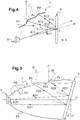
- the figure 4 represents an alternative embodiment of the reflector 7.
- the reflector 7 comprises surface portions P3 designed to reflect in the direction of the polarizing filter 8 light rays received directly from the light source 6. These surface portions P3 are analogous to the surface portions P1 of the picture 2 .
- the reflector 7 further comprises surface portions P4 designed to reflect according to their direction of incidence light rays R12, R12' received from the polarizing filter 8 after emission by the light source 6 then reflection on the polarizing filter 8.
- each surface portion P4 is perpendicular, at at least one point of this surface portion P4, to the incident ray R12, R12' at this point due to a reflection on the polarizing filter 8 of a ray R11, R11' emitted by light source 6.
- the reflection on the polarizing filter 8 is generally partial (because it concerns only the component of the luminous flux concerned having the second polarization).
- some of the light rays emitted by the light source 6 (such as the light rays R11 and R11' shown in figure 4 ) are reflected (in general partially) on the polarizing filter 8 (for example at a point of incidence l) in a light ray R12, R12'.
- the light ray R12, R12' reflected by the polarizing filter 8 is then incident on a surface portion P4 designed (as already mentioned and explained again below) to be perpendicular to this incident light ray R12, R12', so that the reflected light ray R13, R13' is returned in the direction of incidence to the polarizing filter 8.
- part of the light flux concerned (part corresponding to the component having the first polarization) is transmitted through the polarizing filter 8 (here in the direction of the screen 5) so that only a small proportion of the light could possibly be reflected in the direction of the light source 6 by reflection of the rays on the polarizing filter 8, then on the surfaces P3, which would therefore only cause limited heating at the level of the light source 6.
- the presence of the surface portions P4 thus makes it possible to reduce the heating of the light source 6 compared to a solution using only a parabolic surface for the reflector, while giving the surface portions P4 an optical role thanks to which these portions of P4 surface improve the luminous efficiency of the system.
- the surface portions P3 are parabolic, the light source 6 being placed at the focus of these parabolic surfaces.
- each surface portion P4 the orientation of the light ray R12, R12' incident at at least one point of this surface portion P4 coming from the polarizing filter 8 is determined, for example, after emission by the light source 6 and reflection at a point l on the polarizing filter 8.
- this ray R11 is by definition reflected (under form of a ray R12) in the direction of the surface portion P4, forming the same angle ⁇ with respect to the normal N.
- the surface portion P4 Since the surface portion P4 is perpendicular (at at least one point) to the radius R12 to have the desired properties, the surface portion P4 forms at the point concerned this same angle ⁇ with a plane S parallel to the surface of the polarizing filter 8.
- the surface portion P4 can be flat, oriented by the angle ⁇ with respect to the predefined plane S.
- the surface portion P4 can be curved and be perpendicular at each point of its surface to the incident light ray R12 received at the point concerned after emission by the light source 6 and reflection (partial) on the polarizer filter 8.
- the surfaces P4 could be oriented towards specific zones of the polarizing filter 8 in order to improve the homogeneity of the distribution of light on the surface of this polarizing filter 8 (and therefore on the surface of the screen 5).
- the proportion of the surface portions P3 and of the surface portions P4 is variable depending on the reduction in heating of the light source 6 that it is desired to obtain.
- the main direction of emission of the light source 6 (direction referenced X' in figure 5 ) is not perpendicular to the extension plane of the polarizing filter 8.
- the light rays reflected by this polarizing filter 8 are largely directed towards only part of the reflector 7 (upper part in the case of the figure 5 ) and that there would therefore be no interest here in providing in the part P5 (lower part) portions of surfaces designed to reflect light rays received from the polarizing filter 8.
- a surface portion P8 is designed to reflect in the direction of the polarizing filter 8 (light ray R23) a light ray R22 received from the polarizing filter 8 due to the reflection (on the polarizing filter 8) of a light ray R21 reflected by the part (here lower) P5 of the reflector 7.
- Another surface portion P9 is designed to reflect along its direction of incidence a light ray R25 received from the polarizing filter 8 after emission by the light source 6 (ray R24) then reflection on the polarizing filter 8 (in a manner analogous to the portions surface P4 of the figure 4 ).
- the light ray after reflection on the surface portion P9 is referenced R26 in figure 5 .
- ⁇ is the angle formed between the polarizing filter 8 and a plane P' perpendicular to the main direction X'
- the surface portion P8 has (at at least one point) a surface forming an angle ⁇ with respect to a plane S' parallel to the plane P'.
- a light ray R21 directed (at least approximately) along the main direction X' and reflected by the polarizing filter 8 (ray R22) is reflected by the surface portion P8 (at least approximately) along the main direction X', in direction of the polarizing filter 8.
- the surface portion P9 has (at at least one point) a surface forming an angle 2 ⁇ with respect to a plane S" parallel to the plane P'.
- a light ray R24 directed (here approximately) along the main direction X' and reflected by polarizing filter 8 (ray R25) is reflected by surface portion P9 (at least approximately) along its direction of incidence on surface portion P9.
- each surface portion P8, P9 (or a plane tangent to this surface portion) can for example form an angle between ⁇ and 2 ⁇ with respect to the plane P' perpendicular to the main direction X' ( ⁇ being as already indicated l 'angle formed between the polarizing filter 8 and the plane P').
- the surface portions P7, P8, P9 can be positioned according to the application concerned.
- the surface portions P8 could thus for example be placed in a first region of the reflector 7 situated on the side of the light source 6, while the surface portions P9 could be placed in a second region of the reflector 7 situated on the side of the filter polarizer 8.
Landscapes
- Physics & Mathematics (AREA)
- General Physics & Mathematics (AREA)
- Optics & Photonics (AREA)
- Nonlinear Science (AREA)
- Mathematical Physics (AREA)
- Chemical & Material Sciences (AREA)
- Crystallography & Structural Chemistry (AREA)
- Liquid Crystal (AREA)
- Instrument Panels (AREA)
Claims (10)
- Vorrichtung (10) zur Erzeugung eines polarisierten Lichtbündels umfassend:- eine Lichtquelle (6);- einen Reflektor (7) mit aufgeweiteter Form in wenigstens einer Querschnittsebene;- einen Filter (8), der von der Lichtquelle (6) beleuchtet wird und dafür ausgelegt ist, eine erste Polarisierung des Lichts zu übertragen und eine zweite Polarisierung des Lichts zu reflektieren,dadurch gekennzeichnet, dass der Reflektor (7) an der aufgeweiteten Form wenigstens einen ersten Oberflächenteilbereich (P1; P3; P5; P6), der dafür ausgelegt ist, Lichtstrahlen (R1; R20) in Richtung des Filters (8) zu reflektieren, die von der Lichtquelle (6) empfangen werden, und wenigstens einen zweiten Oberflächenteilbereich (P2; P4; P6; P8; P9) umfasst, der dafür ausgelegt ist, Lichtstrahlen (R4; R12; R12'; R22; R25) in Richtung des Filters (8) zu reflektieren, die nach Reflexion durch den Filter (8) vom Filter (8) empfangen werden.
- Vorrichtung nach Anspruch 1, wobei der zweite Oberflächenteilbereich (P2; P4; P9) dafür ausgelegt ist, Lichtstrahlen (R4; R12; R12'; R25) in Richtung des Filters (8) zu reflektieren, die vom Filter (8) durch Reflexion von Lichtstrahlen (R3; R11; R11'; R24) auf dem Filter (8) empfangen werden, die direkt von der Lichtquelle (6) empfangen werden.
- Vorrichtung nach Anspruch 1, wobei der zweite Oberflächenteilbereich (P8) dafür ausgelegt ist, Lichtstrahlen (R22) in Richtung des Filters (8) zu reflektieren, die vom Filter (8) durch Reflexion von Lichtstrahlen (R21) auf dem Filter (8) empfangen werden, die vom Reflektor (7) empfangen werden.
- Vorrichtung nach einem der Ansprüche 1 bis 3, wobei der zweite Oberflächenteilbereich (P4; P9) dafür ausgelegt ist, Lichtstrahlen (R12; R12'; R25), die vom Filter (8) durch Reflexion auf dem Filter (8) empfangen werden, je nach ihrer Einfallrichtung zu reflektieren.
- Vorrichtung nach einem der Ansprüche 1 bis 3, wobei der zweite Oberflächenteilbereich (P2; P7) senkrecht zur Hauptemissionsrichtung (X; X') der Lichtquelle (6) verläuft.
- Vorrichtung nach einem der Ansprüche 1 bis 5, wobei der zweite Oberflächenteilbereich eben ist.
- Vorrichtung nach einem der Ansprüche 1 bis 6, wobei der erste Oberflächenteilbereich (P1) dafür ausgelegt ist, die Strahlen (R1), die von der Lichtquelle (6) empfangen werden, in einer Richtung (X) senkrecht zur Erstreckungsebene des Filters (8) zu reflektieren.
- Bilderzeugungsvorrichtung (3) umfassend eine Vorrichtung zur Erzeugung eines Lichtbündels (10) nach einem der vorhergehenden Ansprüche und einen Schirm (5), der dafür angeordnet ist, das Lichtbündel zu empfangen.
- Vorrichtung nach Anspruch 8, wobei der Schirm (5) einen Eingangspolarisator (12) umfasst, der dafür ausgelegt ist, die erste Polarisierung zu übertragen.
- Head-up-Display (1) umfassend eine Bilderzeugungsvorrichtung (3) nach Anspruch 9 und eine Bildprojektionsvorrichtung (4), die geeignet ist, die Bilder, die von der Bilderzeugungsvorrichtung (3) erzeugt werden, in Richtung eines teilweise transparenten Blattes (2) zu übertragen.
Applications Claiming Priority (1)
| Application Number | Priority Date | Filing Date | Title |
|---|---|---|---|
| FR1753600A FR3065535B1 (fr) | 2017-04-25 | 2017-04-25 | Dispositif de production d'un faisceau lumineux polarise, dispositif de generation d'image et afficheur tete haute |
Publications (2)
| Publication Number | Publication Date |
|---|---|
| EP3396444A1 EP3396444A1 (de) | 2018-10-31 |
| EP3396444B1 true EP3396444B1 (de) | 2022-08-17 |
Family
ID=59253728
Family Applications (1)
| Application Number | Title | Priority Date | Filing Date |
|---|---|---|---|
| EP18169367.2A Active EP3396444B1 (de) | 2017-04-25 | 2018-04-25 | Vorrichtung zur erzeugung eines polarisierten lichtstrahls, bilderzeugungsvorrichtung und head-up-display |
Country Status (2)
| Country | Link |
|---|---|
| EP (1) | EP3396444B1 (de) |
| FR (1) | FR3065535B1 (de) |
Family Cites Families (1)
| Publication number | Priority date | Publication date | Assignee | Title |
|---|---|---|---|---|
| US7352124B2 (en) * | 2004-09-28 | 2008-04-01 | Goldeneye, Inc. | Light recycling illumination systems utilizing light emitting diodes |
-
2017
- 2017-04-25 FR FR1753600A patent/FR3065535B1/fr not_active Expired - Fee Related
-
2018
- 2018-04-25 EP EP18169367.2A patent/EP3396444B1/de active Active
Also Published As
| Publication number | Publication date |
|---|---|
| EP3396444A1 (de) | 2018-10-31 |
| FR3065535B1 (fr) | 2021-09-17 |
| FR3065535A1 (fr) | 2018-10-26 |
Similar Documents
| Publication | Publication Date | Title |
|---|---|---|
| FR3028963A1 (fr) | Systeme de protection pour afficheur, notamment tete haute, et afficheur associe | |
| EP3507542B1 (de) | Beleuchtungs- und/oder signalisierungsvorrichtung, insbesondere für ein kraftfahrzeug | |
| FR3054328B1 (fr) | Dispositif de generation d'image et afficheur tete haute | |
| FR3064339A1 (fr) | Module lumineux avec correction de chromatisme | |
| EP3396444B1 (de) | Vorrichtung zur erzeugung eines polarisierten lichtstrahls, bilderzeugungsvorrichtung und head-up-display | |
| FR3020148A1 (fr) | Systeme de generation d'images pour afficheur et afficheur associe | |
| EP3685216B1 (de) | Head-up-anzeigevorrichtung | |
| FR3020147A1 (fr) | Systeme de generation d'images pour afficheur et afficheur associe pour vehicule automobile | |
| FR3039664B1 (fr) | Systeme de projection pour afficheur et afficheur tete haute associe | |
| EP3273283B1 (de) | Vorrichtung zur bilderzeugung und head-up-display, das eine solche bilderzeugungsvorrichtung umfasst | |
| EP3807698B1 (de) | Projektionsvorrichtung für ein head-up-anzeigesystem für einen kraftfahrzeugfahrer und entsprechendes system | |
| FR2999141A1 (fr) | Dispositif d'affichage tete haute compact | |
| FR2639722A1 (fr) | Systeme optique du type afficheur tete moyenne ou tete haute pour vehicules automobiles | |
| FR3039658A1 (fr) | Dispositif d'emission d'un faisceau lumineux destine a former une image et afficheur associe | |
| FR2858068A1 (fr) | Systeme de projection d'images pour viseur tete haute | |
| EP3921694B1 (de) | Anzeigeeinheit und kombiinstrument | |
| FR3143139A1 (fr) | Dispositif de génération d’image et afficheur tête-haute comprenant un tel dispositif | |
| FR3039656A1 (fr) | Dispositif de formation d'image et afficheur tete haute comprenant un tel dispositif | |
| FR3067128A1 (fr) | Imagerie pour vehicule automobile avec ecran | |
| FR3054021A1 (fr) | Dispositif lumineux de projection d’image variable | |
| FR3054330A1 (fr) | Dispositif de generation d'images et afficheur tete haute associe | |
| FR3049723A1 (fr) | Afficheur tete haute | |
| FR3006460A1 (fr) | Ecran et dispositif d'affichage en retroprojection |
Legal Events
| Date | Code | Title | Description |
|---|---|---|---|
| PUAI | Public reference made under article 153(3) epc to a published international application that has entered the european phase |
Free format text: ORIGINAL CODE: 0009012 |
|
| STAA | Information on the status of an ep patent application or granted ep patent |
Free format text: STATUS: THE APPLICATION HAS BEEN PUBLISHED |
|
| AK | Designated contracting states |
Kind code of ref document: A1 Designated state(s): AL AT BE BG CH CY CZ DE DK EE ES FI FR GB GR HR HU IE IS IT LI LT LU LV MC MK MT NL NO PL PT RO RS SE SI SK SM TR |
|
| AX | Request for extension of the european patent |
Extension state: BA ME |
|
| STAA | Information on the status of an ep patent application or granted ep patent |
Free format text: STATUS: REQUEST FOR EXAMINATION WAS MADE |
|
| 17P | Request for examination filed |
Effective date: 20190425 |
|
| RBV | Designated contracting states (corrected) |
Designated state(s): AL AT BE BG CH CY CZ DE DK EE ES FI FR GB GR HR HU IE IS IT LI LT LU LV MC MK MT NL NO PL PT RO RS SE SI SK SM TR |
|
| STAA | Information on the status of an ep patent application or granted ep patent |
Free format text: STATUS: EXAMINATION IS IN PROGRESS |
|
| 17Q | First examination report despatched |
Effective date: 20201207 |
|
| GRAP | Despatch of communication of intention to grant a patent |
Free format text: ORIGINAL CODE: EPIDOSNIGR1 |
|
| STAA | Information on the status of an ep patent application or granted ep patent |
Free format text: STATUS: GRANT OF PATENT IS INTENDED |
|
| INTG | Intention to grant announced |
Effective date: 20220301 |
|
| GRAS | Grant fee paid |
Free format text: ORIGINAL CODE: EPIDOSNIGR3 |
|
| GRAA | (expected) grant |
Free format text: ORIGINAL CODE: 0009210 |
|
| STAA | Information on the status of an ep patent application or granted ep patent |
Free format text: STATUS: THE PATENT HAS BEEN GRANTED |
|
| AK | Designated contracting states |
Kind code of ref document: B1 Designated state(s): AL AT BE BG CH CY CZ DE DK EE ES FI FR GB GR HR HU IE IS IT LI LT LU LV MC MK MT NL NO PL PT RO RS SE SI SK SM TR |
|
| REG | Reference to a national code |
Ref country code: CH Ref legal event code: EP |
|
| REG | Reference to a national code |
Ref country code: DE Ref legal event code: R096 Ref document number: 602018039306 Country of ref document: DE |
|
| REG | Reference to a national code |
Ref country code: IE Ref legal event code: FG4D Free format text: LANGUAGE OF EP DOCUMENT: FRENCH |
|
| REG | Reference to a national code |
Ref country code: AT Ref legal event code: REF Ref document number: 1512559 Country of ref document: AT Kind code of ref document: T Effective date: 20220915 |
|
| REG | Reference to a national code |
Ref country code: NL Ref legal event code: MP Effective date: 20220817 |
|
| REG | Reference to a national code |
Ref country code: LT Ref legal event code: MG9D |
|
| PG25 | Lapsed in a contracting state [announced via postgrant information from national office to epo] |
Ref country code: SE Free format text: LAPSE BECAUSE OF FAILURE TO SUBMIT A TRANSLATION OF THE DESCRIPTION OR TO PAY THE FEE WITHIN THE PRESCRIBED TIME-LIMIT Effective date: 20220817 Ref country code: RS Free format text: LAPSE BECAUSE OF FAILURE TO SUBMIT A TRANSLATION OF THE DESCRIPTION OR TO PAY THE FEE WITHIN THE PRESCRIBED TIME-LIMIT Effective date: 20220817 Ref country code: PT Free format text: LAPSE BECAUSE OF FAILURE TO SUBMIT A TRANSLATION OF THE DESCRIPTION OR TO PAY THE FEE WITHIN THE PRESCRIBED TIME-LIMIT Effective date: 20221219 Ref country code: NO Free format text: LAPSE BECAUSE OF FAILURE TO SUBMIT A TRANSLATION OF THE DESCRIPTION OR TO PAY THE FEE WITHIN THE PRESCRIBED TIME-LIMIT Effective date: 20221117 Ref country code: NL Free format text: LAPSE BECAUSE OF FAILURE TO SUBMIT A TRANSLATION OF THE DESCRIPTION OR TO PAY THE FEE WITHIN THE PRESCRIBED TIME-LIMIT Effective date: 20220817 Ref country code: LV Free format text: LAPSE BECAUSE OF FAILURE TO SUBMIT A TRANSLATION OF THE DESCRIPTION OR TO PAY THE FEE WITHIN THE PRESCRIBED TIME-LIMIT Effective date: 20220817 Ref country code: LT Free format text: LAPSE BECAUSE OF FAILURE TO SUBMIT A TRANSLATION OF THE DESCRIPTION OR TO PAY THE FEE WITHIN THE PRESCRIBED TIME-LIMIT Effective date: 20220817 Ref country code: FI Free format text: LAPSE BECAUSE OF FAILURE TO SUBMIT A TRANSLATION OF THE DESCRIPTION OR TO PAY THE FEE WITHIN THE PRESCRIBED TIME-LIMIT Effective date: 20220817 |
|
| REG | Reference to a national code |
Ref country code: AT Ref legal event code: MK05 Ref document number: 1512559 Country of ref document: AT Kind code of ref document: T Effective date: 20220817 |
|
| PG25 | Lapsed in a contracting state [announced via postgrant information from national office to epo] |
Ref country code: PL Free format text: LAPSE BECAUSE OF FAILURE TO SUBMIT A TRANSLATION OF THE DESCRIPTION OR TO PAY THE FEE WITHIN THE PRESCRIBED TIME-LIMIT Effective date: 20220817 Ref country code: IS Free format text: LAPSE BECAUSE OF FAILURE TO SUBMIT A TRANSLATION OF THE DESCRIPTION OR TO PAY THE FEE WITHIN THE PRESCRIBED TIME-LIMIT Effective date: 20221217 Ref country code: HR Free format text: LAPSE BECAUSE OF FAILURE TO SUBMIT A TRANSLATION OF THE DESCRIPTION OR TO PAY THE FEE WITHIN THE PRESCRIBED TIME-LIMIT Effective date: 20220817 Ref country code: GR Free format text: LAPSE BECAUSE OF FAILURE TO SUBMIT A TRANSLATION OF THE DESCRIPTION OR TO PAY THE FEE WITHIN THE PRESCRIBED TIME-LIMIT Effective date: 20221118 |
|
| PG25 | Lapsed in a contracting state [announced via postgrant information from national office to epo] |
Ref country code: SM Free format text: LAPSE BECAUSE OF FAILURE TO SUBMIT A TRANSLATION OF THE DESCRIPTION OR TO PAY THE FEE WITHIN THE PRESCRIBED TIME-LIMIT Effective date: 20220817 Ref country code: RO Free format text: LAPSE BECAUSE OF FAILURE TO SUBMIT A TRANSLATION OF THE DESCRIPTION OR TO PAY THE FEE WITHIN THE PRESCRIBED TIME-LIMIT Effective date: 20220817 Ref country code: ES Free format text: LAPSE BECAUSE OF FAILURE TO SUBMIT A TRANSLATION OF THE DESCRIPTION OR TO PAY THE FEE WITHIN THE PRESCRIBED TIME-LIMIT Effective date: 20220817 Ref country code: DK Free format text: LAPSE BECAUSE OF FAILURE TO SUBMIT A TRANSLATION OF THE DESCRIPTION OR TO PAY THE FEE WITHIN THE PRESCRIBED TIME-LIMIT Effective date: 20220817 Ref country code: CZ Free format text: LAPSE BECAUSE OF FAILURE TO SUBMIT A TRANSLATION OF THE DESCRIPTION OR TO PAY THE FEE WITHIN THE PRESCRIBED TIME-LIMIT Effective date: 20220817 Ref country code: AT Free format text: LAPSE BECAUSE OF FAILURE TO SUBMIT A TRANSLATION OF THE DESCRIPTION OR TO PAY THE FEE WITHIN THE PRESCRIBED TIME-LIMIT Effective date: 20220817 |
|
| RAP4 | Party data changed (patent owner data changed or rights of a patent transferred) |
Owner name: VALEO COMFORT AND DRIVING ASSISTANCE |
|
| REG | Reference to a national code |
Ref country code: DE Ref legal event code: R097 Ref document number: 602018039306 Country of ref document: DE |
|
| PG25 | Lapsed in a contracting state [announced via postgrant information from national office to epo] |
Ref country code: SK Free format text: LAPSE BECAUSE OF FAILURE TO SUBMIT A TRANSLATION OF THE DESCRIPTION OR TO PAY THE FEE WITHIN THE PRESCRIBED TIME-LIMIT Effective date: 20220817 Ref country code: EE Free format text: LAPSE BECAUSE OF FAILURE TO SUBMIT A TRANSLATION OF THE DESCRIPTION OR TO PAY THE FEE WITHIN THE PRESCRIBED TIME-LIMIT Effective date: 20220817 |
|
| PLBE | No opposition filed within time limit |
Free format text: ORIGINAL CODE: 0009261 |
|
| STAA | Information on the status of an ep patent application or granted ep patent |
Free format text: STATUS: NO OPPOSITION FILED WITHIN TIME LIMIT |
|
| PG25 | Lapsed in a contracting state [announced via postgrant information from national office to epo] |
Ref country code: AL Free format text: LAPSE BECAUSE OF FAILURE TO SUBMIT A TRANSLATION OF THE DESCRIPTION OR TO PAY THE FEE WITHIN THE PRESCRIBED TIME-LIMIT Effective date: 20220817 |
|
| P01 | Opt-out of the competence of the unified patent court (upc) registered |
Effective date: 20230528 |
|
| 26N | No opposition filed |
Effective date: 20230519 |
|
| PG25 | Lapsed in a contracting state [announced via postgrant information from national office to epo] |
Ref country code: SI Free format text: LAPSE BECAUSE OF FAILURE TO SUBMIT A TRANSLATION OF THE DESCRIPTION OR TO PAY THE FEE WITHIN THE PRESCRIBED TIME-LIMIT Effective date: 20220817 |
|
| REG | Reference to a national code |
Ref country code: CH Ref legal event code: PL |
|
| GBPC | Gb: european patent ceased through non-payment of renewal fee |
Effective date: 20230425 |
|
| PG25 | Lapsed in a contracting state [announced via postgrant information from national office to epo] |
Ref country code: LU Free format text: LAPSE BECAUSE OF NON-PAYMENT OF DUE FEES Effective date: 20230425 |
|
| REG | Reference to a national code |
Ref country code: BE Ref legal event code: MM Effective date: 20230430 |
|
| PG25 | Lapsed in a contracting state [announced via postgrant information from national office to epo] |
Ref country code: MC Free format text: LAPSE BECAUSE OF FAILURE TO SUBMIT A TRANSLATION OF THE DESCRIPTION OR TO PAY THE FEE WITHIN THE PRESCRIBED TIME-LIMIT Effective date: 20220817 |
|
| PG25 | Lapsed in a contracting state [announced via postgrant information from national office to epo] |
Ref country code: GB Free format text: LAPSE BECAUSE OF NON-PAYMENT OF DUE FEES Effective date: 20230425 |
|
| PG25 | Lapsed in a contracting state [announced via postgrant information from national office to epo] |
Ref country code: MC Free format text: LAPSE BECAUSE OF FAILURE TO SUBMIT A TRANSLATION OF THE DESCRIPTION OR TO PAY THE FEE WITHIN THE PRESCRIBED TIME-LIMIT Effective date: 20220817 Ref country code: LI Free format text: LAPSE BECAUSE OF NON-PAYMENT OF DUE FEES Effective date: 20230430 Ref country code: GB Free format text: LAPSE BECAUSE OF NON-PAYMENT OF DUE FEES Effective date: 20230425 Ref country code: CH Free format text: LAPSE BECAUSE OF NON-PAYMENT OF DUE FEES Effective date: 20230430 |
|
| REG | Reference to a national code |
Ref country code: IE Ref legal event code: MM4A |
|
| PG25 | Lapsed in a contracting state [announced via postgrant information from national office to epo] |
Ref country code: BE Free format text: LAPSE BECAUSE OF NON-PAYMENT OF DUE FEES Effective date: 20230430 |
|
| PG25 | Lapsed in a contracting state [announced via postgrant information from national office to epo] |
Ref country code: IE Free format text: LAPSE BECAUSE OF NON-PAYMENT OF DUE FEES Effective date: 20230425 |
|
| PG25 | Lapsed in a contracting state [announced via postgrant information from national office to epo] |
Ref country code: IE Free format text: LAPSE BECAUSE OF NON-PAYMENT OF DUE FEES Effective date: 20230425 |
|
| PG25 | Lapsed in a contracting state [announced via postgrant information from national office to epo] |
Ref country code: IT Free format text: LAPSE BECAUSE OF FAILURE TO SUBMIT A TRANSLATION OF THE DESCRIPTION OR TO PAY THE FEE WITHIN THE PRESCRIBED TIME-LIMIT Effective date: 20220817 |
|
| PG25 | Lapsed in a contracting state [announced via postgrant information from national office to epo] |
Ref country code: BG Free format text: LAPSE BECAUSE OF FAILURE TO SUBMIT A TRANSLATION OF THE DESCRIPTION OR TO PAY THE FEE WITHIN THE PRESCRIBED TIME-LIMIT Effective date: 20220817 |
|
| PG25 | Lapsed in a contracting state [announced via postgrant information from national office to epo] |
Ref country code: BG Free format text: LAPSE BECAUSE OF FAILURE TO SUBMIT A TRANSLATION OF THE DESCRIPTION OR TO PAY THE FEE WITHIN THE PRESCRIBED TIME-LIMIT Effective date: 20220817 |
|
| PGFP | Annual fee paid to national office [announced via postgrant information from national office to epo] |
Ref country code: DE Payment date: 20250411 Year of fee payment: 8 |
|
| PGFP | Annual fee paid to national office [announced via postgrant information from national office to epo] |
Ref country code: FR Payment date: 20250429 Year of fee payment: 8 |
|
| PG25 | Lapsed in a contracting state [announced via postgrant information from national office to epo] |
Ref country code: CY Free format text: LAPSE BECAUSE OF FAILURE TO SUBMIT A TRANSLATION OF THE DESCRIPTION OR TO PAY THE FEE WITHIN THE PRESCRIBED TIME-LIMIT; INVALID AB INITIO Effective date: 20180425 |
|
| PG25 | Lapsed in a contracting state [announced via postgrant information from national office to epo] |
Ref country code: HU Free format text: LAPSE BECAUSE OF FAILURE TO SUBMIT A TRANSLATION OF THE DESCRIPTION OR TO PAY THE FEE WITHIN THE PRESCRIBED TIME-LIMIT; INVALID AB INITIO Effective date: 20180425 |
|
| PG25 | Lapsed in a contracting state [announced via postgrant information from national office to epo] |
Ref country code: TR Free format text: LAPSE BECAUSE OF FAILURE TO SUBMIT A TRANSLATION OF THE DESCRIPTION OR TO PAY THE FEE WITHIN THE PRESCRIBED TIME-LIMIT Effective date: 20220817 |