EP3396304A1 - Feedback system for pitch-adjustable blades of aircraft bladed rotor - Google Patents
Feedback system for pitch-adjustable blades of aircraft bladed rotor Download PDFInfo
- Publication number
- EP3396304A1 EP3396304A1 EP18169088.4A EP18169088A EP3396304A1 EP 3396304 A1 EP3396304 A1 EP 3396304A1 EP 18169088 A EP18169088 A EP 18169088A EP 3396304 A1 EP3396304 A1 EP 3396304A1
- Authority
- EP
- European Patent Office
- Prior art keywords
- magnetic field
- magnetic
- sensor
- magnet
- coil
- Prior art date
- Legal status (The legal status is an assumption and is not a legal conclusion. Google has not performed a legal analysis and makes no representation as to the accuracy of the status listed.)
- Granted
Links
- 230000004907 flux Effects 0.000 claims abstract description 47
- 238000001514 detection method Methods 0.000 claims description 21
- 238000000034 method Methods 0.000 claims description 21
- 230000004044 response Effects 0.000 claims description 6
- 230000000694 effects Effects 0.000 description 13
- 230000035699 permeability Effects 0.000 description 8
- 239000000463 material Substances 0.000 description 7
- 238000013459 approach Methods 0.000 description 4
- 230000008859 change Effects 0.000 description 4
- 239000003570 air Substances 0.000 description 3
- 239000000567 combustion gas Substances 0.000 description 3
- CWYNVVGOOAEACU-UHFFFAOYSA-N Fe2+ Chemical compound [Fe+2] CWYNVVGOOAEACU-UHFFFAOYSA-N 0.000 description 2
- 230000004323 axial length Effects 0.000 description 2
- 238000010276 construction Methods 0.000 description 2
- 230000006870 function Effects 0.000 description 2
- 230000000116 mitigating effect Effects 0.000 description 2
- 230000004048 modification Effects 0.000 description 2
- 238000012986 modification Methods 0.000 description 2
- 238000004806 packaging method and process Methods 0.000 description 2
- 239000012080 ambient air Substances 0.000 description 1
- 230000015572 biosynthetic process Effects 0.000 description 1
- 230000008878 coupling Effects 0.000 description 1
- 238000010168 coupling process Methods 0.000 description 1
- 238000005859 coupling reaction Methods 0.000 description 1
- 230000001419 dependent effect Effects 0.000 description 1
- 238000006073 displacement reaction Methods 0.000 description 1
- 238000005516 engineering process Methods 0.000 description 1
- 230000001747 exhibiting effect Effects 0.000 description 1
- 230000002349 favourable effect Effects 0.000 description 1
- 210000003746 feather Anatomy 0.000 description 1
- 239000000446 fuel Substances 0.000 description 1
- 239000007789 gas Substances 0.000 description 1
- 231100001261 hazardous Toxicity 0.000 description 1
- 230000001939 inductive effect Effects 0.000 description 1
- 238000009434 installation Methods 0.000 description 1
- 230000010354 integration Effects 0.000 description 1
- 230000007246 mechanism Effects 0.000 description 1
- 239000002184 metal Substances 0.000 description 1
- 239000007769 metal material Substances 0.000 description 1
- 229910000595 mu-metal Inorganic materials 0.000 description 1
- 230000009467 reduction Effects 0.000 description 1
- 230000007704 transition Effects 0.000 description 1
Images


Classifications
-
- B—PERFORMING OPERATIONS; TRANSPORTING
- B64—AIRCRAFT; AVIATION; COSMONAUTICS
- B64C—AEROPLANES; HELICOPTERS
- B64C11/00—Propellers, e.g. of ducted type; Features common to propellers and rotors for rotorcraft
- B64C11/30—Blade pitch-changing mechanisms
-
- B—PERFORMING OPERATIONS; TRANSPORTING
- B64—AIRCRAFT; AVIATION; COSMONAUTICS
- B64C—AEROPLANES; HELICOPTERS
- B64C11/00—Propellers, e.g. of ducted type; Features common to propellers and rotors for rotorcraft
- B64C11/30—Blade pitch-changing mechanisms
- B64C11/301—Blade pitch-changing mechanisms characterised by blade position indicating means
-
- B—PERFORMING OPERATIONS; TRANSPORTING
- B64—AIRCRAFT; AVIATION; COSMONAUTICS
- B64D—EQUIPMENT FOR FITTING IN OR TO AIRCRAFT; FLIGHT SUITS; PARACHUTES; ARRANGEMENTS OR MOUNTING OF POWER PLANTS OR PROPULSION TRANSMISSIONS IN AIRCRAFT
- B64D27/00—Arrangement or mounting of power plant in aircraft; Aircraft characterised thereby
- B64D27/02—Aircraft characterised by the type or position of power plant
- B64D27/10—Aircraft characterised by the type or position of power plant of gas-turbine type
-
- G—PHYSICS
- G01—MEASURING; TESTING
- G01D—MEASURING NOT SPECIALLY ADAPTED FOR A SPECIFIC VARIABLE; ARRANGEMENTS FOR MEASURING TWO OR MORE VARIABLES NOT COVERED IN A SINGLE OTHER SUBCLASS; TARIFF METERING APPARATUS; MEASURING OR TESTING NOT OTHERWISE PROVIDED FOR
- G01D5/00—Mechanical means for transferring the output of a sensing member; Means for converting the output of a sensing member to another variable where the form or nature of the sensing member does not constrain the means for converting; Transducers not specially adapted for a specific variable
- G01D5/12—Mechanical means for transferring the output of a sensing member; Means for converting the output of a sensing member to another variable where the form or nature of the sensing member does not constrain the means for converting; Transducers not specially adapted for a specific variable using electric or magnetic means
- G01D5/14—Mechanical means for transferring the output of a sensing member; Means for converting the output of a sensing member to another variable where the form or nature of the sensing member does not constrain the means for converting; Transducers not specially adapted for a specific variable using electric or magnetic means influencing the magnitude of a current or voltage
- G01D5/142—Mechanical means for transferring the output of a sensing member; Means for converting the output of a sensing member to another variable where the form or nature of the sensing member does not constrain the means for converting; Transducers not specially adapted for a specific variable using electric or magnetic means influencing the magnitude of a current or voltage using Hall-effect devices
- G01D5/147—Mechanical means for transferring the output of a sensing member; Means for converting the output of a sensing member to another variable where the form or nature of the sensing member does not constrain the means for converting; Transducers not specially adapted for a specific variable using electric or magnetic means influencing the magnitude of a current or voltage using Hall-effect devices influenced by the movement of a third element, the position of Hall device and the source of magnetic field being fixed in respect to each other
-
- G—PHYSICS
- G01—MEASURING; TESTING
- G01D—MEASURING NOT SPECIALLY ADAPTED FOR A SPECIFIC VARIABLE; ARRANGEMENTS FOR MEASURING TWO OR MORE VARIABLES NOT COVERED IN A SINGLE OTHER SUBCLASS; TARIFF METERING APPARATUS; MEASURING OR TESTING NOT OTHERWISE PROVIDED FOR
- G01D5/00—Mechanical means for transferring the output of a sensing member; Means for converting the output of a sensing member to another variable where the form or nature of the sensing member does not constrain the means for converting; Transducers not specially adapted for a specific variable
- G01D5/12—Mechanical means for transferring the output of a sensing member; Means for converting the output of a sensing member to another variable where the form or nature of the sensing member does not constrain the means for converting; Transducers not specially adapted for a specific variable using electric or magnetic means
- G01D5/14—Mechanical means for transferring the output of a sensing member; Means for converting the output of a sensing member to another variable where the form or nature of the sensing member does not constrain the means for converting; Transducers not specially adapted for a specific variable using electric or magnetic means influencing the magnitude of a current or voltage
- G01D5/20—Mechanical means for transferring the output of a sensing member; Means for converting the output of a sensing member to another variable where the form or nature of the sensing member does not constrain the means for converting; Transducers not specially adapted for a specific variable using electric or magnetic means influencing the magnitude of a current or voltage by varying inductance, e.g. by a movable armature
-
- G—PHYSICS
- G01—MEASURING; TESTING
- G01P—MEASURING LINEAR OR ANGULAR SPEED, ACCELERATION, DECELERATION, OR SHOCK; INDICATING PRESENCE, ABSENCE, OR DIRECTION, OF MOVEMENT
- G01P3/00—Measuring linear or angular speed; Measuring differences of linear or angular speeds
- G01P3/42—Devices characterised by the use of electric or magnetic means
- G01P3/44—Devices characterised by the use of electric or magnetic means for measuring angular speed
- G01P3/48—Devices characterised by the use of electric or magnetic means for measuring angular speed by measuring frequency of generated current or voltage
- G01P3/481—Devices characterised by the use of electric or magnetic means for measuring angular speed by measuring frequency of generated current or voltage of pulse signals
- G01P3/488—Devices characterised by the use of electric or magnetic means for measuring angular speed by measuring frequency of generated current or voltage of pulse signals delivered by variable reluctance detectors
-
- F—MECHANICAL ENGINEERING; LIGHTING; HEATING; WEAPONS; BLASTING
- F02—COMBUSTION ENGINES; HOT-GAS OR COMBUSTION-PRODUCT ENGINE PLANTS
- F02C—GAS-TURBINE PLANTS; AIR INTAKES FOR JET-PROPULSION PLANTS; CONTROLLING FUEL SUPPLY IN AIR-BREATHING JET-PROPULSION PLANTS
- F02C6/00—Plural gas-turbine plants; Combinations of gas-turbine plants with other apparatus; Adaptations of gas- turbine plants for special use
- F02C6/20—Adaptations of gas-turbine plants for driving vehicles
- F02C6/206—Adaptations of gas-turbine plants for driving vehicles the vehicles being airscrew driven
-
- F—MECHANICAL ENGINEERING; LIGHTING; HEATING; WEAPONS; BLASTING
- F05—INDEXING SCHEMES RELATING TO ENGINES OR PUMPS IN VARIOUS SUBCLASSES OF CLASSES F01-F04
- F05D—INDEXING SCHEME FOR ASPECTS RELATING TO NON-POSITIVE-DISPLACEMENT MACHINES OR ENGINES, GAS-TURBINES OR JET-PROPULSION PLANTS
- F05D2220/00—Application
- F05D2220/30—Application in turbines
- F05D2220/32—Application in turbines in gas turbines
- F05D2220/323—Application in turbines in gas turbines for aircraft propulsion, e.g. jet engines
-
- G—PHYSICS
- G01—MEASURING; TESTING
- G01D—MEASURING NOT SPECIALLY ADAPTED FOR A SPECIFIC VARIABLE; ARRANGEMENTS FOR MEASURING TWO OR MORE VARIABLES NOT COVERED IN A SINGLE OTHER SUBCLASS; TARIFF METERING APPARATUS; MEASURING OR TESTING NOT OTHERWISE PROVIDED FOR
- G01D2205/00—Indexing scheme relating to details of means for transferring or converting the output of a sensing member
- G01D2205/40—Position sensors comprising arrangements for concentrating or redirecting magnetic flux
Definitions
- the disclosure relates generally to aircraft engines, and more particularly to feedback systems for pitch-adjustable blades of bladed rotors of aircraft.
- angular position On aircraft propeller systems that have variable pitch propeller blades, it is desirable to provide accurate feedback on the angular position, sometimes referred to as "beta angle", of the propeller blades.
- Such feedback can be used to control such angular position as desired in a feedback control loop based on a requested set point.
- Such angular position feedback can also be used to ensure that the propeller is not inadvertently commanded to transition into excessively low or reverse beta angles, which could potentially be hazardous in some phases of flight of the aircraft.
- An engine has a feedback system for pitch-adjustable blades of an aircraft bladed rotor where the system comprises:
- the pole piece is disposed between the magnet and the feedback rotor.
- the magnetic shield comprises an aperture for permitting passage of the magnetic field through the magnetic shield via the aperture.
- the pole piece extends into the aperture in the magnetic shield.
- At least part of the magnetic shield is disposed inside a sensor housing containing the magnet, the coil and the pole piece.
- At least part of the magnetic shield is disposed outside a sensor housing containing the magnet, the coil and the pole piece.
- the pole piece is disposed between the magnet and the feedback rotor.
- the magnetic shield comprises a bottom wall and one or more side walls cooperatively defining a receptacle within which part of the coil and part of the pole piece are received.
- the bottom wall includes an aperture for permitting passage of the magnetic field through the bottom wall.
- the coil is a first coil and the sensor signal is a first sensor signal indicative of the variation in the magnetic field on a first channel.
- the system comprises a second coil configured to generate a second sensor signal indicative of the variation in the magnetic field on a second channel.
- Embodiments may include combinations of the above features.
- the senor comprises a housing containing the magnet, the pole piece and the coil. In some embodiments at least part of the magnetic shield is disposed inside the housing.
- the senor comprises a housing containing the magnet, the pole piece and the coil. In some embodiments at least part of the magnetic shield is disposed outside the housing.
- the magnetic shield comprises a wall with an aperture for permitting passage of the magnetic field through the magnetic shield via the aperture.
- the pole piece extends into the aperture in the wall of the magnetic shield.
- the coil is a first coil and the sensor signal is a first sensor signal indicative of the variation in the magnetic field on a first channel.
- the sensor comprises a second coil configured to generate a second sensor signal indicative of the variation in the magnetic field on a second channel redundant to the first channel.
- the magnetic shield comprises a bottom wall and one or more side walls cooperatively defining a receptacle within which part of the coil and part of the pole piece are received.
- the bottom wall includes an aperture for permitting passage of the magnetic field through the bottom wall.
- the pole piece extends into the aperture in the wall of the magnetic shield.
- Embodiments may include combinations of the above features.
- the method comprises directing the first magnetic flux through an aperture in a wall of a magnetic shield defining the one or more magnetic return paths.
- the method comprises detecting the variation in the magnetic field in a redundant manner.
- Embodiments may include combinations of the above features.
- the systems, sensors and methods disclosed herein make use of the detection of variations in a magnetic field caused by the movement (e.g., passage) of one or more moving detectable features to generate one or more signals indicative of the angular position of the pitch-adjustable blades.
- the systems, sensors and methods disclosed herein may use a magnetically permeable shield that guides some magnetic flux in the magnetic field along one or more magnetic return paths in order to promote a configuration of the magnetic field that is favorable to accurate detection of the one or more detectable features.
- the systems, sensors and methods disclosed herein may permit the detection of such detectable feature(s) using a location near one or more respective edges of the one or more detectable feature(s) by mitigating edge effects on the magnetic field.
- FIG. 1 is an axial cross-section view of an exemplary aircraft engine 10 coupled to bladed rotor 12 (e.g., propeller) for an aircraft (not shown).
- Engine 10 may be a gas turbine engine, of a type typically provided for use in subsonic flight, comprising inlet 14, into which ambient air is received, (e.g., multi-stage) compressor 16 for pressurizing the air, combustor 18 in which the compressed air is mixed with fuel and ignited for generating an annular stream of hot combustion gases, and turbine section 20 for extracting energy from the combustion gases.
- Turbine section 20 may comprise compressor turbine 22, which may drive compressor 16 and other accessories, and power turbine 24 which may rotate independently from compressor turbine 22 and which may drive power shaft 26 which may be drivingly coupled to bladed rotor 12 via reduction gearbox 28.
- Combustion gases may be evacuated through exhaust duct 30 after passing through turbine section 20.
- Bladed rotor 12 may comprise a plurality of pitch-adjustable blades 32 extending radially from hub 34 and being circumferentially distributed relative to hub 34 of bladed rotor 12.
- Bladed rotor 12 may be a variable pitch bladed rotor where each blade 32 may be angularly adjustable about a respective axis B. Accordingly, each blade 32 may be rotatable about axis B using any suitable mechanism so that the pitch of blades 32 may be adjusted collectively in unison for different phases of operation (e.g., feather, forward thrust and reverse) of engine 10 and/or of an aircraft to which engine 10 and bladed rotor 12 may be mounted.
- bladed rotor 12 as a propeller suitable for fixed-wing aircraft, it is understood that aspects of this disclosure are also applicable to other types of bladed rotors such as main rotors and tail rotors of rotary-wing aircraft such as helicopters for example.
- Bladed rotor 12 may be mounted for rotation about rotation axis R.
- rotation axis R may, but not necessarily, be coaxial with an axis of rotation of power shaft 26.
- FIG. 1 also schematically shows an angular (pitch) position feedback system 36 (referred hereinafter as “feedback system 36") associated with bladed rotor 12 and which is described below.
- feedback system 36 angular (pitch) position feedback system 36
- FIG. 2 is a schematic representation of a partial axial cross-section of an exemplary feedback system 36 of engine 10 for providing feedback on the angular position of adjustable blades 32 of bladed rotor 12.
- Feedback system 36 may be configured to interface with known or other adjustable blade systems to permit the detection of the angular position (e.g., beta angle) of adjustable blades 32.
- feedback system 36 may comprise feedback rotor 38, sensor 40 and detection unit 42.
- Feedback rotor 38 may be configured to rotate with (e.g., be mechanically coupled to) bladed rotor 12 about rotation axis R.
- feedback rotor 38 may be configured to rotate at the same rotational speed and coaxially with bladed rotor 12.
- the rotation axis of feedback rotor 38 may not necessarily be coaxial with the rotation axis of bladed rotor 12.
- Feedback rotor 38 may be axially displaceable along rotation axis R to a plurality of axial positions where an axial position of feedback rotor 38 may correspond to a respective angular (pitch) position of adjustable blades 32.
- Feedback rotor 38 may comprise circumferentially-spaced apart and detectable features 44 useful for detecting the axial position of the feedback rotor 38 as feedback rotor 38 and bladed rotor 12 rotate. Feedback rotor 38 may consequently be useful for detecting the angular position of adjustable blades 32 by way of a correlation.
- Feedback rotor 38 may comprise an annular member 46 or wheel with detectable features 44 protruding therefrom. In some embodiments, detectable features 44 and sensor 40 may be disposed on a radially-outer side of annular member 46. Alternatively, detectable features 44 and sensor 40 could be disposed on a radially-inner side of annular member 46 instead.
- detectable features 44 may be of any suitable configurations permitting the passage of such detectable features 44 to be detected by sensor 40.
- detectable features 44 may, for example, comprise one or more of the following: protrusions, teeth, walls, voids, recesses and/or other singularities.
- detectable features 44 may all be of the same configuration or may comprise features of different configurations.
- one or more detectable features 44 may be separate components individually secured to annular member 46 of feedback rotor 38.
- one or more detectable features 44 may be integrally formed with annular member 46 so that feedback rotor 38 may have a unitary construction.
- Sensor 40 may be an inductive (e.g., proximity) sensor suitable for non-contact detection of the passage of detectable features 44 as feedback rotor 38 rotates about rotation axis R.
- Sensor 40 may be mounted adjacent feedback rotor 38 and secured to some stationary structure of engine 10 via bracket 48 for example or other suitable means.
- Sensor 40 may be mounted adjacent to rotating feedback rotor 38.
- sensor 40 may be configured as a variable reluctance sensor (commonly called a VR sensor) suitable for detecting the proximity of (e.g., ferrous) features.
- detectable features 44 may be configured to intersect the magnetic field and cause a detectable variation in (e.g., disrupt) the magnetic field that is generated by sensor 40.
- detectable features 44 may be of any suitable type which would cause the passage of such detectable feature 44 near sensor 40 to provide a change in magnetic permeability within the magnetic field generated by sensor 40 and which could result in a detectable variation in the magnetic field.
- detectable features 44 may comprise ferrous or other metallic material(s).
- Detectable features 44 may be of any type suitable to cause a variation in the magnetic field due to a change in presence of feature(s) 44 in the magnetic field.
- Detection unit 42 may be operatively connected to sensor 40 for receiving one or more sensor signals 50 and configured to generate one or more feedback signals 52 indicative of the angular position of adjustable blades 32.
- detection unit 42 may form part of a Full Authority Digital Engine Control (FADEC) which may, for example, comprise one or more digital computer(s) or other data processors, sometimes referred to as electronic engine controller(s) (EEC) and related accessories that control at least some aspects of performance of engine 10.
- FADEC Full Authority Digital Engine Control
- detection unit 42 may comprise one or more computing devices including, but not limited to, a digital computer, a processor (e.g. a microprocessor), and a memory.
- sensor signal(s) 50 may also be used to provide feedback on the rotational speed of bladed rotor 12. Accordingly, detection unit 42 may, in some embodiments be configured to generate feedback signal(s) 52 indicative of the rotational speed of bladed rotor 12.
- feedback system 36 may be referred to as an "Np/beta" feedback system where Np represents the rotational speed of bladed rotor 12 and beta represents the angular position of adjustable blades 32.
- detection unit 42 may perform other tasks associated with functions such as synchronization and/or synchrophasing of propellers for example.
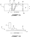
- FIG. 3A is a schematic top view of sensor 40 in relation to detectable features 44 about to be detected by sensor 40 as feedback rotor 38 rotates about rotation axis R (see FIG. 2 ).
- FIG. 3B is a schematic side view of sensor 40 in relation to detectable features 44 about to be detected by sensor 40 as feedback rotor 38 rotates about rotation axis R.
- FIGS. 3A and 3B each show a portion of annular member 46 that has been flattened for clarity of illustration.
- Detectable features 44 may have the form of elongated teeth or walls that protrude radially outwardly from a radially outer surface of annular member 46.
- the number of detectable features 44 circumferentially distributed around feedback rotor 38 may be used in conjunction with a digital counting function of detection unit 42 for the purpose of determining the rotation speed of bladed rotor 12 for example as the passage of detectable features 44 is detected by sensor 40 and detection unit 42 as feedback rotor 38 rotates relative to sensor 40.
- some of detectable features 44 may be elongated and substantially aligned with (i.e., parallel to) rotation axis R.
- One or more other elongated detectable features 44 may be oriented to be non-parallel (e.g., oblique) to rotation axis R.
- the different orientation between adjacent elongated detectable features 44 may provide different detection times between the adjacent detectable features 44 at different axial positions of feedback rotor 38 relative to sensor 40 and such different detection timing may be used to correlate the axial position of feedback rotor 38 to the angular position of adjustable blades 32.
- Approaches for extracting meaningful information from the passing of detectable features 44 are disclosed in US Patent Publication No. 2015/0139798 A1 .
- Detectable features 44 may comprise axial edges or terminations 44A where elongated detectable features 44 terminate in the axial direction relative to rotation axis R (see FIG. 2 ). In some situations, it may be desirable to permit sensor 40 to be positioned near or at edges 44A and still be able to accurately detect the passing of detectable features 44 despite any edge-related effects that may influence sensor 40. This may allow to more fully use of the axial dimension of feedback rotor 38 and promote efficient packaging of feedback rotor 38 by not requiring extra axial length of feedback rotor 38 for the purpose of avoiding such edge-related effects. In some situations, the amount of axial travel of feedback rotor 38 may be dependent on the specific type of bladed rotor 12 and installation constraints. Sensor 40 as described herein may be configured to permit accurate detection of detectable features 44 by mitigating edge-related effects.
- FIGS. 4A and 4B are a partial front view and a bottom view of an exemplary sensor 40 of feedback system 36.
- Sensor 40 may comprise housing 54 and magnetic shield 56.
- Housing 54 may have a generally cylindrical shape with a sensor axis SA.
- sensor axis SA may be a radial line relative to axis of rotation R shown in FIG. 2 .
- housing 54 may have a circular outer cross-sectional profile.
- magnetic shield 56 may be disposed externally to housing 54.
- magnetic shield 56 may be mounted by suitable means to the exterior of housing 54.
- Magnetic shield 56 may be made from one or more materials of relatively high magnetic permeability to readily support the formation of a magnetic field within itself.
- magnetic shield 56 may provide one or more low-reluctance return paths for magnetic flux as explained below.
- magnetic shield 56 may be made from mu-metal or any suitable material(s) exhibiting a relatively high relative magnetic permeability.
- the material(s) of magnetic shield 56 may have a relative magnetic permeability value that is between 20,000 and 100,000 for example.
- the material(s) of magnetic shield 56 may have a relative magnetic permeability value that is between 80,000 and 100,000 for example.
- magnetic shield 56 may comprise bottom wall 56A and one or more side walls 56B cooperatively defining a receptacle (e.g., can) within which part of housing 54 and/or other internal components of sensor 40 may be received.
- bottom wall 56A may comprise aperture 58 extending through bottom wall 56A.
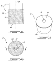
- FIG. 5 is a perspective view of magnetic shield 56 having a receptacle configuration, showing aperture 58 extending through bottom wall 56A of magnetic shield 56.
- magnetic shield 56 may have a single-piece unitary construction wherein bottom wall 56A and side wall(s) 56B are integrally formed.
- bottom wall 56A and side wall(s) 56B may comprise separate components (e.g., washer and sleeve) that are subsequently assembled together to permit magnetic coupling therebetween.
- the configuration of magnetic shield 56 shown in FIG. 5 may be suitable for fitting over the exterior of housing 54 of sensor 40.
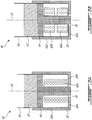
- FIGS. 6A and 6B are cross-sectional views of two exemplary embodiments of sensor 40 taken along line 6-6 in FIG. 4B .
- sensor 40 may have a single-channel configuration and accordingly may have a single coil 60A disposed inside of housing 54 and configured to generate one or more sensor signals 50 (see FIG. 2 ) in response to variations in the magnetic field caused by the movement of detectable features 44 by sensor 40.
- sensor 40 may have a multi-channel configuration wherein sensor signals 50 are acquired in a redundant manner. For example, FIGS.
- coil 60A and 6B show different exemplary configurations of coils 60A and 60B for a two-channel configuration of sensor 40 where two coils 60A and 60B that are electrically-isolated from each other may provide redundant sensor signals 50 in response to variations in the magnetic field.
- coil 60A may be configured to generate one or more first sensor signals 50 (e.g., voltages) on a first channel in response to the variations in the magnetic field
- coil 60B may be configured to generate one or more second sensor signals 50 (e.g., voltages) on a second channel in response to the variations in the magnetic field.
- Sensor 40 may also comprise magnet 62 disposed inside housing 54 and generating a magnetic field for intersecting feedback rotor 38.
- magnet 62 may be a permanent magnet.
- Magnet 62 may be stationary and mounted adjacent the rotating feedback rotor 38.
- sensor 40 may comprise pole piece 64 configured to direct the magnetic field generated by magnet 62 toward feedback rotor 38 at a location expected to be occupied by one or more features 44.
- Pole piece 64 may be coupled to one pole of magnet 62 and be configured to direct the magnetic field radially inwardly (or outwardly) generally along sensor axis SA and toward feedback rotor 38 so that the magnetic flux exiting the distal end of pole piece 64 may intersect detectable features 44 as features 44 move past sensor 40.
- Pole piece 64 may be a structure comprising material of relatively high magnetic permeability that serves to direct the magnetic field generated by magnet 62 toward features 44. Pole piece 64 may be coupled to a pole of magnet 62 and in a sense extend the pole of magnet 62 toward feedback rotor 38. Pole piece 64 may be disposed between magnet 62 and feedback rotor 38.
- coils 60A and 60B may be wound around pole piece 64 where coil 60A may be a radially-inner coil and coil 60B may be a radially-outer coil that surrounds coil 60B.
- coils 60A and 60B may be concentric coils nested one inside the other and may accordingly have different diameters.
- coils 60A and 60B may be of substantially the same height along sensor axis SA. Coils 60A, 60B may be stationary relative to magnet 62 and mounted in the magnetic field of magnet 62.
- coils 60A and 60B may be wound around pole piece 64 but may be disposed at different elevations (i.e., stacked) along sensor axis SA.
- coils 60A and 60B may be substantially identical (e.g., of substantially the same diameter and height along sensor axis SA).
- coils 60A and 60B may have different configurations from each other.
- Magnetic shield 56 may be stationary relative to magnet 62 and mounted in the magnetic field of magnet 62.
- magnetic shield 56 may have a receptacle configuration within which coils 60A and 60B are partially or entirely received to that coils 60A and 60B may be shielded by magnetic shield 56. Bottom wall 56A of magnetic shield 56 may be disposed between coils 60A, 60B and feedback rotor 38.
- magnetic shield 56 may be symmetric across sensor axis SA to define two or more (e.g., symmetric) return paths for magnetic flux as explained below.
- magnetic shield 56 may be axisymmetric about sensor axis 40.
- pole piece 64 may be received inside the receptacle defined by the configuration of magnetic shield 56.
- Aperture 58 in bottom wall 56A of magnetic shield 56 may permit some of the magnetic field that is guided by pole piece 64 to pass through magnetic shield 56 via aperture 58.
- aperture 58 may be centrally located within bottom wall 56A.
- sensor axis 40 may pass through aperture 58.
- a distal portion of pole piece 64 may extend into or through aperture 58.
- Aperture 58 may be sized and positioned to provide an air gap between magnetic shield 56 and pole piece 64.
- FIG. 7 is cross-sectional view of another exemplary sensor 40 of feedback system 36 of FIG. 2 .
- the configuration of sensor 40 shown in FIG. 7 may have functional similarities with the configuration of sensor 40 shown in FIG. 6A .
- FIG. 7 however shows a configuration where magnetic shield 56 is disposed inside of housing 54 of sensor 40.
- magnetic shield 56 may be mounted by suitable means to the interior of housing 54.
- part(s) of permeable magnetic shield 56 may be disposed inside or outside of housing 54 to provide one or more desired magnetic return paths.
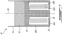
- FIGS. 8A and 8B are respective schematic front and bottom views of another exemplary embodiment of sensor 40 of feedback system 36.
- FIG. 8C is a cross-sectional view of sensor 40 of FIGS. 8A and 8B taken along line 8-8 in FIG. 8B .
- magnetic shield 56 may have different configurations to achieve different types and amounts of magnetic flux guiding in different applications.
- the specific geometry of magnetic shield 56 may vary based on the specific configurations of sensor 40 and of feedback rotor 38 for example.
- magnetic shield 56 may comprise only bottom wall 56A, which may be adequate in some applications.
- magnetic shield 56 may have a "washer" configuration with aperture 58 formed therethrough.
- Magnetic shield 56, 56A may be disposed outside or inside of housing 54.
- FIGS. 9A and 9B are respective schematic front and bottom views of another exemplary embodiment of sensor 40 of feedback system 36.
- FIG. 9C is a cross-sectional view of sensor 40 of FIGS. 9A and 9B taken along line 9-9 in FIG. 9B .
- magnetic shield 56 may comprise only side wall(s) 56B, which may be adequate in some applications.
- magnetic shield 56 may have an open-ended "sleeve" configuration.
- Magnetic shield 56, 56B may be disposed outside or inside of housing 54.
- FIGS. 10A and 10B are respective schematic front and bottom views of another exemplary embodiment of sensor 40 of feedback system 36.
- magnetic shield 56 may not necessarily have an axisymmetric configuration.
- magnetic shield 56 or portions 56C, 56D thereof may be disposed at locations where providing one or more magnetic return paths is more desirable based on the specific configuration of feedback system 36.
- the passage of feature 44 by sensor 40 may produce a disturbance or variation having some directionality in the magnetic field generated by magnet 62. Accordingly, in some embodiments, it may be adequate to provide magnetic return paths at the locations of portions 56C and 56D as illustrated.
- portions 56C and 56D may define only part of the receptacle defined by magnetic shield 56 illustrated in FIG. 5 .
- each portion 56C, 56D may comprise a bottom wall portion and/or a side wall portion. Portions 56C, 56D may be disposed outside or inside of housing 54. In some embodiments, portions 56C, 56D may define separate magnetic return paths at different desired locations.
- FIGS. 11A and 11B are cross-sectional views of sensor 40 of FIG. 6A without magnetic shield 56 and with magnetic shield 56 respectively to show the effect of magnetic shield 56 on leakage magnetic flux 66 within the magnetic field generated by magnet 62.
- the magnetic field generated by magnet 62 may not entirely and completely be directed to feedback rotor 38 via the distal end of pole piece 64.
- Such leakage magnetic flux 66 may be partly due to the change in diameter of pole piece 64 as it extends along sensor axis SA. It is understood that in the configuration of sensor 40 shown, leakage magnetic flux 66 could be present substantially around sensor axis SA in a substantially axisymmetric manner even though FIGS. 11A and 11 B show fewer flux lines for clarity.
- FIG. 11B shows the effect of magnetic shield 56 on such leakage magnetic flux 66.
- Bottom wall 56A and side wall(s) 56B of magnetic shield 56 may provide one or more low-reluctance magnetic return paths for efficiently guiding leakage magnetic flux 66 toward the opposite pole of magnet 62.
- magnetic shield 56 may provide controlled and predictable magnetic return path(s) for such leakage magnetic flux 66 so that the effects of such leakage magnetic flux 66 on coils 60A and 60B may be reduced.
- magnetic shield 56 may shunt most of leakage magnetic flux 66 back toward the opposite magnetic pole of magnet 62 thereby isolating such leakage magnetic flux 66 from external influences (e.g., detectable features 44).
- magnetic shield 56 may more efficiently close the magnetic circuit between the two opposite (i.e., North and South) poles of magnet 62 for leakage magnetic flux 66.
- magnetic shield 56 may provide two or more highly-permeable magnetic return paths that may be symmetric across sensor axis SA or a plurality of highly-permeable magnetic return paths that may be angularly distributed about sensor axis SA in an axisymmetric manner.
- FIGS. 12A and 12B are cross-sectional views of sensor 40 of FIG. 6A without magnetic shield 56 and with magnetic shield 56 respectively to show the effect of magnetic shield 56 on the magnetic field generated by magnet 62 near edge 44A of detectable feature 44.
- the return path for the magnetic flux has substantially symmetrical permeability across sensor axis 44 provided by sufficient amounts of material (e.g., metal) from detectable feature 44 being located on each side of sensor 40 so an unshielded sensor as shown in FIG. 12A may be suitable.
- edge 44A of detectable feature 44 approaches sensor 40
- the different amounts of material from detectable feature 44 on either sides of sensor 40 can result in asymmetric permeability and skew the magnetic field of the unshielded sensor.
- the skewing of the magnetic field exhibited with the unshielded sensor is schematically illustrated in FIG. 12A by line M being offset from sensor axis SA and by the asymmetry of magnetic flux 66 and 68.
- Such edge-related effect exhibited in the magnetic field as edge 44A is approached by sensor 40 may cause some error with sensor signals 50 produced by coils 60A and 60B.
- Such errors can include some error(s) in the determined axial position of feedback rotor 38 and/or some discrepancies between supposedly redundant sensor signals 50 obtained from separate coils 60A and 60B of different channels.
- this error can increase exponentially as edge 44A approaches the unshielded sensor and can therefore limit the amount of useable axial movement available for a given length of detectable features 44.
- additional length of detectable features 44 may be required beyond each end of the axial travel of feedback rotor 38 relative to the unshielded sensor in order to avoid potential errors from such edge effects.
- Leakage magnetic flux 66 passing across coils 60A and 60B in the unshielded sensor of FIG. 12A may be influenced by an external magnetic event such as the change in presence or movement (e.g., passage) of detectable feature 44 in the magnetic field. Since the two coils 60A and 60B can be of different sizes and/or positions, each coil 60A and 60B may see a different amount of varying magnetic flux due to the asymmetry in the magnetic field and this may cause a discrepancy (e.g., channel A-B split) between sensor signals 50 obtained from separate coils 60A and 60B of different channels.
- a discrepancy e.g., channel A-B split
- magnetic shield 56 to sensor 40 as shown in FIG. 12B provides highly-permeable magnetic return path(s) that may be symmetric across sensor axis SA and which can reduce the edge-related effect otherwise exhibited using the unshielded sensor and consequently reduce the likelihood of errors.
- the use of magnetic shield 56 may, in some embodiments, result in a more symmetric magnetic field even near edge 44A of detectable feature 44. This may result in an increase in available amount of useable axial displacement of feedback rotor 38 for a given axial length of detectable feature 44. Consequently, this may result in more efficient packaging of feedback system 36.
- the use of magnetic shield 56 may, by shunting some leakage magnetic flux 66 which does not intersect with detectable features 44, cause coils 60A, 60B to mostly only see varying magnetic flux 68 that has been directed by pole piece 64 to feedback rotor 38 and that has been influenced by the passing of detectable feature 44. Accordingly, this may reduce the likelihood of discrepancy (e.g., channel A-B split) between sensor signals 50 obtained from separate redundant coils 60A and 60B of different channels.
- Magnetic shield 56 may guide some leakage magnetic flux 66 that does not intersect detectable features 44 along one or more magnetic return paths of relatively low reluctance. Accordingly, the use of magnetic shield 56 may promote a more symmetric magnetic field as shown by line M being aligned with sensor axis SA in FIG. 12B .
- FIG. 13 is a flowchart of a method 1000 for providing angular (pitch) position feedback for pitch-adjustable blades 32 of aircraft bladed rotor 12.
- method 1000 may be carried out using sensor 40 as disclosed herein but the execution of method 40 is not limited to the specific systems 36 and sensors 40 disclosed herein.
- method 1000 may comprise:
- Method 1000 may comprise using pole piece 64 to direct the magnetic field from a first pole of magnet 62 generating the magnetic field toward a location that features 44 are expected to occupy.
- Second magnetic flux 66 may comprise magnetic flux leaking from pole piece 64.
- the one or more magnetic return paths may guide second magnetic flux 66 toward an opposite second pole of magnet 62.
- the one or more magnetic return paths may comprise two or more (e.g., symmetric) magnetic return paths.
- Method 1000 may comprise detecting the one or more variations in the magnetic field in a redundant manner (e.g., using separate and electrically isolated coils 60A and 60B).
- Method 1000 may comprise directing the first magnetic flux through aperture 58 in wall 56A of magnetic shield 56 that is disposed between magnet 62 and moving features 44.
- Method 1000 may comprise directing the first magnetic flux through aperture 58 in wall 56A of magnetic shield 56 defining the one or more magnetic return paths.
Landscapes
- Engineering & Computer Science (AREA)
- Aviation & Aerospace Engineering (AREA)
- Physics & Mathematics (AREA)
- General Physics & Mathematics (AREA)
- Transmission And Conversion Of Sensor Element Output (AREA)
- Measurement Of Length, Angles, Or The Like Using Electric Or Magnetic Means (AREA)
- Measuring Magnetic Variables (AREA)
Abstract
Description
- The disclosure relates generally to aircraft engines, and more particularly to feedback systems for pitch-adjustable blades of bladed rotors of aircraft.
- On aircraft propeller systems that have variable pitch propeller blades, it is desirable to provide accurate feedback on the angular position, sometimes referred to as "beta angle", of the propeller blades. Such feedback can be used to control such angular position as desired in a feedback control loop based on a requested set point. Such angular position feedback can also be used to ensure that the propeller is not inadvertently commanded to transition into excessively low or reverse beta angles, which could potentially be hazardous in some phases of flight of the aircraft.
- An engine according to one disclosed, non-limiting embodiment has a feedback system for pitch-adjustable blades of an aircraft bladed rotor where the system comprises:
- a feedback rotor configured to rotate with the aircraft bladed rotor about a rotation axis, the feedback rotor being axially displaceable along the rotation axis to a plurality of axial positions, the axial position of the feedback rotor corresponding to a respective pitch position of the pitch-adjustable blades, the feedback rotor comprising features spaced circumferentially around the feedback rotor;
- a stationary magnet mounted in the engine adjacent the rotating feedback rotor, the magnet having a magnetic field;
- a pole piece coupled to a first pole of the magnet and configured to direct the magnetic field toward the features;
- a coil mounted in the magnetic field and being stationary relative to the magnet, the coil configured to generate a sensor signal indicative of a variation in the magnetic field caused by movement of one or more of the features in the magnetic field as the feedback rotor rotates relative to the magnet;
- a magnetic shield mounted in the magnetic field and being stationary relative to the magnet, the magnetic shield defining a magnetic return path for some magnetic flux of the magnetic field exiting the pole piece toward an opposite second pole of the magnet; and
- a detection unit operatively connected to the coil and configured to generate a feedback signal indicative of the respective pitch position of the pitch-adjustable blades in response to the sensor signal received from the coil.
- In an embodiment according to the previous embodiment, the pole piece is disposed between the magnet and the feedback rotor.
- In another embodiment according to any of the previous embodiments, the magnetic shield comprises an aperture for permitting passage of the magnetic field through the magnetic shield via the aperture.
- In another embodiment according to any of the previous embodiments, the pole piece extends into the aperture in the magnetic shield.
- In another embodiment according to any of the previous embodiments, at least part of the magnetic shield is disposed inside a sensor housing containing the magnet, the coil and the pole piece.
- In another embodiment according to any of the previous embodiments, at least part of the magnetic shield is disposed outside a sensor housing containing the magnet, the coil and the pole piece.
- In another embodiment according to any of the previous embodiments, the pole piece is disposed between the magnet and the feedback rotor.
- In another embodiment according to any of the previous embodiments, the magnetic shield comprises a bottom wall and one or more side walls cooperatively defining a receptacle within which part of the coil and part of the pole piece are received. The bottom wall includes an aperture for permitting passage of the magnetic field through the bottom wall.
- In another embodiment according to any of the previous embodiments, the coil is a first coil and the sensor signal is a first sensor signal indicative of the variation in the magnetic field on a first channel. The system comprises a second coil configured to generate a second sensor signal indicative of the variation in the magnetic field on a second channel.
- Embodiments may include combinations of the above features.
- A sensor for detecting a moving feature according to another disclosed non-limiting embodiment comprises:
- a magnet having a magnetic field;
- a pole piece coupled to a first pole of the magnet and directing the magnetic field toward the feature;
- a coil mounted in the magnetic field, the coil configured to generate a sensor signal indicative of a variation in the magnetic field caused by movement of the feature in the magnetic field; and
- a magnetic shield mounted in the magnetic field, the magnetic shield defining a magnetic return path for some magnetic flux of the magnetic field exiting the pole piece toward an opposite second pole of the magnet.
- In an embodiment according to the previous embodiment, the sensor comprises a housing containing the magnet, the pole piece and the coil. In some embodiments at least part of the magnetic shield is disposed inside the housing.
- In another embodiment according to any of the previous embodiments, the sensor comprises a housing containing the magnet, the pole piece and the coil. In some embodiments at least part of the magnetic shield is disposed outside the housing.
- In another embodiment according to any of the previous embodiments, the magnetic shield comprises a wall with an aperture for permitting passage of the magnetic field through the magnetic shield via the aperture.
- In another embodiment according to any of the previous embodiments, the pole piece extends into the aperture in the wall of the magnetic shield.
- In another embodiment according to any of the previous embodiments, the coil is a first coil and the sensor signal is a first sensor signal indicative of the variation in the magnetic field on a first channel. The sensor comprises a second coil configured to generate a second sensor signal indicative of the variation in the magnetic field on a second channel redundant to the first channel.
- In another embodiment according to any of the previous embodiments, the magnetic shield comprises a bottom wall and one or more side walls cooperatively defining a receptacle within which part of the coil and part of the pole piece are received. The bottom wall includes an aperture for permitting passage of the magnetic field through the bottom wall.
- In another embodiment according to any of the previous embodiments, the pole piece extends into the aperture in the wall of the magnetic shield.
- Embodiments may include combinations of the above features.
- A method for providing pitch position feedback for pitch-adjustable blades of an aircraft bladed rotor according to another disclosed non-limiting embodiment comprises:
- directing a magnetic field from a first pole of a magnet toward a location that moving features indicative of a pitch of the pitch-adjustable blades are expected to occupy as the moving features move relative to the magnet, the magnetic field including first magnetic flux intersecting the location that the moving features are expected to occupy and second magnetic flux not intersecting the location that the moving features are expected to occupy;
- guiding the second magnetic flux toward an opposite second pole of the magnet along one or more magnetic return paths;
- detecting a variation in the magnetic field caused by movement of one or more of the moving features in the magnetic field; and
- generating a signal indicative of the pitch of the pitch-adjustable blades based on the detection of the variation in the magnetic field.
- In an embodiment according to the previous embodiment, the method comprises directing the first magnetic flux through an aperture in a wall of a magnetic shield defining the one or more magnetic return paths.
- In another embodiment according to any of the previous embodiments, the method comprises detecting the variation in the magnetic field in a redundant manner.
- Embodiments may include combinations of the above features.
- Further details of these and other aspects of the subject matter of this application will be apparent from the detailed description included below and the drawings.
- Reference is now made to the accompanying drawings, in which:
-
FIG. 1 is an axial cross-section view of an aircraft engine coupled to a bladed rotor with pitch-adjustable blades; -
FIG. 2 is a schematic representation of a partial axial cross-section of an exemplary pitch feedback system for the pitch-adjustable blades of the bladed rotor; -
FIGS. 3A and 3B are schematic respective top and side views of a sensor and a feedback rotor for the feedback system ofFIG. 2 ; -
FIGS. 4A and 4B are respective schematic front and bottom views of an exemplary sensor of the feedback system ofFIG. 2 ; -
FIG. 5 is a perspective view of a magnetic shield of the sensor ofFIGS. 4A and 4B showing an aperture through a bottom wall of the magnetic shield; -
FIGS. 6A and 6B are cross-sectional views of two exemplary embodiments of the sensor ofFIGS. 4A and 4B taken along line 6-6 inFIG. 4B ; -
FIG. 7 is a cross-sectional view of another exemplary sensor of the feedback system ofFIG. 2 ; -
FIGS. 8A and 8B are respective schematic front and bottom views of another exemplary sensor of the feedback system ofFIG. 2 ; -
FIG. 8C is a cross-sectional view of the sensor ofFIGS. 8A and 8B taken along line 8-8 inFIG. 8B ; -
FIGS. 9A and 9B are respective schematic front and bottom views of another exemplary sensor of the feedback system ofFIG. 2 ; -
FIG. 9C is a cross-sectional view of the sensor ofFIGS. 9A and 9B taken along line 9-9 inFIG. 9B ; -
FIGS. 10A and 10B are respective schematic front and bottom views of another exemplary sensor of the feedback system ofFIG. 2 ; -
FIGS. 11A and 11B are cross-sectional views of a sensor without and with a magnetic shield respectively to show the effect of the magnetic shield on leakage magnetic flux; -
FIGS. 12A and 12B are cross-sectional views of the sensor ofFIGS. 11A and 11B respectively to show the effect of the magnetic shield on a magnetic field near an edge of a detectable feature; and -
FIG. 13 is a flowchart of a method for providing pitch position feedback for pitch-adjustable blades of an aircraft bladed rotor. - The following description discloses systems, sensors and methods useful in providing feedback on the angular (i.e., pitch) position of pitch-adjustable blades on aircraft bladed rotors such as aircraft propellers for example. In some embodiments, the systems, sensors and methods disclosed herein make use of the detection of variations in a magnetic field caused by the movement (e.g., passage) of one or more moving detectable features to generate one or more signals indicative of the angular position of the pitch-adjustable blades. In some embodiments, the systems, sensors and methods disclosed herein may use a magnetically permeable shield that guides some magnetic flux in the magnetic field along one or more magnetic return paths in order to promote a configuration of the magnetic field that is favorable to accurate detection of the one or more detectable features. In some embodiments, the systems, sensors and methods disclosed herein may permit the detection of such detectable feature(s) using a location near one or more respective edges of the one or more detectable feature(s) by mitigating edge effects on the magnetic field.
- Aspects of various embodiments are described through reference to the drawings.
-
FIG. 1 is an axial cross-section view of anexemplary aircraft engine 10 coupled to bladed rotor 12 (e.g., propeller) for an aircraft (not shown).Engine 10 may be a gas turbine engine, of a type typically provided for use in subsonic flight, comprisinginlet 14, into which ambient air is received, (e.g., multi-stage)compressor 16 for pressurizing the air,combustor 18 in which the compressed air is mixed with fuel and ignited for generating an annular stream of hot combustion gases, andturbine section 20 for extracting energy from the combustion gases.Turbine section 20 may comprisecompressor turbine 22, which may drivecompressor 16 and other accessories, andpower turbine 24 which may rotate independently fromcompressor turbine 22 and which may drivepower shaft 26 which may be drivingly coupled tobladed rotor 12 viareduction gearbox 28. Combustion gases may be evacuated throughexhaust duct 30 after passing throughturbine section 20. -
Bladed rotor 12 may comprise a plurality of pitch-adjustable blades 32 extending radially fromhub 34 and being circumferentially distributed relative tohub 34 ofbladed rotor 12.Bladed rotor 12 may be a variable pitch bladed rotor where eachblade 32 may be angularly adjustable about a respective axis B. Accordingly, eachblade 32 may be rotatable about axis B using any suitable mechanism so that the pitch ofblades 32 may be adjusted collectively in unison for different phases of operation (e.g., feather, forward thrust and reverse) ofengine 10 and/or of an aircraft to whichengine 10 andbladed rotor 12 may be mounted. Even thoughFIG. 1 illustrates bladedrotor 12 as a propeller suitable for fixed-wing aircraft, it is understood that aspects of this disclosure are also applicable to other types of bladed rotors such as main rotors and tail rotors of rotary-wing aircraft such as helicopters for example. -
Bladed rotor 12 may be mounted for rotation about rotation axis R. In some embodiments, rotation axis R may, but not necessarily, be coaxial with an axis of rotation ofpower shaft 26.FIG. 1 also schematically shows an angular (pitch) position feedback system 36 (referred hereinafter as "feedback system 36") associated withbladed rotor 12 and which is described below. -
FIG. 2 is a schematic representation of a partial axial cross-section of anexemplary feedback system 36 ofengine 10 for providing feedback on the angular position ofadjustable blades 32 ofbladed rotor 12.Feedback system 36 may be configured to interface with known or other adjustable blade systems to permit the detection of the angular position (e.g., beta angle) ofadjustable blades 32. In some embodiments,feedback system 36 may comprisefeedback rotor 38,sensor 40 anddetection unit 42. -
Feedback rotor 38 may be configured to rotate with (e.g., be mechanically coupled to)bladed rotor 12 about rotation axis R. For example, in some embodiments,feedback rotor 38 may be configured to rotate at the same rotational speed and coaxially withbladed rotor 12. However, it is understood that the rotation axis offeedback rotor 38 may not necessarily be coaxial with the rotation axis ofbladed rotor 12.Feedback rotor 38 may be axially displaceable along rotation axis R to a plurality of axial positions where an axial position offeedback rotor 38 may correspond to a respective angular (pitch) position ofadjustable blades 32.Feedback rotor 38 may comprise circumferentially-spaced apart anddetectable features 44 useful for detecting the axial position of thefeedback rotor 38 asfeedback rotor 38 andbladed rotor 12 rotate.Feedback rotor 38 may consequently be useful for detecting the angular position ofadjustable blades 32 by way of a correlation.Feedback rotor 38 may comprise anannular member 46 or wheel withdetectable features 44 protruding therefrom. In some embodiments,detectable features 44 andsensor 40 may be disposed on a radially-outer side ofannular member 46. Alternatively,detectable features 44 andsensor 40 could be disposed on a radially-inner side ofannular member 46 instead. - In various embodiments,
detectable features 44 may be of any suitable configurations permitting the passage of suchdetectable features 44 to be detected bysensor 40. In some embodiments,detectable features 44 may, for example, comprise one or more of the following: protrusions, teeth, walls, voids, recesses and/or other singularities. In various embodiments,detectable features 44 may all be of the same configuration or may comprise features of different configurations. In some embodiments, one or moredetectable features 44 may be separate components individually secured toannular member 46 offeedback rotor 38. In some embodiments, one or moredetectable features 44 may be integrally formed withannular member 46 so thatfeedback rotor 38 may have a unitary construction. - Approaches for the integration of
feedback rotor 38 withbladed rotor 12 to permit axial movement offeedback rotor 38 to correspond with the angular position ofadjustable blades 32 and the use ofdetectable features 44 to obtain feedback of angular position ofadjustable blades 32 are disclosed inUS Patent Publication No. 2015/0139798 A1 (title: SYSTEM AND METHOD FOR ELECTRONIC PROPELLER BLADE ANGLE POSITION FEEDBACK). -
Sensor 40 may be an inductive (e.g., proximity) sensor suitable for non-contact detection of the passage ofdetectable features 44 asfeedback rotor 38 rotates about rotationaxis R. Sensor 40 may be mountedadjacent feedback rotor 38 and secured to some stationary structure ofengine 10 viabracket 48 for example or other suitable means.Sensor 40 may be mounted adjacent torotating feedback rotor 38. In some embodiments,sensor 40 may be configured as a variable reluctance sensor (commonly called a VR sensor) suitable for detecting the proximity of (e.g., ferrous) features. Accordingly,detectable features 44 may be configured to intersect the magnetic field and cause a detectable variation in (e.g., disrupt) the magnetic field that is generated bysensor 40. For example,detectable features 44 may be of any suitable type which would cause the passage of suchdetectable feature 44 nearsensor 40 to provide a change in magnetic permeability within the magnetic field generated bysensor 40 and which could result in a detectable variation in the magnetic field. In various embodiments,detectable features 44 may comprise ferrous or other metallic material(s).Detectable features 44 may be of any type suitable to cause a variation in the magnetic field due to a change in presence of feature(s) 44 in the magnetic field. -
Detection unit 42 may be operatively connected tosensor 40 for receiving one or more sensor signals 50 and configured to generate one or more feedback signals 52 indicative of the angular position ofadjustable blades 32. In various embodiments,detection unit 42 may form part of a Full Authority Digital Engine Control (FADEC) which may, for example, comprise one or more digital computer(s) or other data processors, sometimes referred to as electronic engine controller(s) (EEC) and related accessories that control at least some aspects of performance ofengine 10. Accordingly,detection unit 42 may comprise one or more computing devices including, but not limited to, a digital computer, a processor (e.g. a microprocessor), and a memory. In some embodiments, sensor signal(s) 50 may also be used to provide feedback on the rotational speed ofbladed rotor 12. Accordingly,detection unit 42 may, in some embodiments be configured to generate feedback signal(s) 52 indicative of the rotational speed ofbladed rotor 12. In some embodiments,feedback system 36 may be referred to as an "Np/beta" feedback system where Np represents the rotational speed ofbladed rotor 12 and beta represents the angular position ofadjustable blades 32. In some embodiments,detection unit 42 may perform other tasks associated with functions such as synchronization and/or synchrophasing of propellers for example. -
FIG. 3A is a schematic top view ofsensor 40 in relation todetectable features 44 about to be detected bysensor 40 asfeedback rotor 38 rotates about rotation axis R (seeFIG. 2 ).FIG. 3B is a schematic side view ofsensor 40 in relation todetectable features 44 about to be detected bysensor 40 asfeedback rotor 38 rotates about rotation axis R.FIGS. 3A and 3B each show a portion ofannular member 46 that has been flattened for clarity of illustration.Detectable features 44 may have the form of elongated teeth or walls that protrude radially outwardly from a radially outer surface ofannular member 46. The number ofdetectable features 44 circumferentially distributed aroundfeedback rotor 38 may be used in conjunction with a digital counting function ofdetection unit 42 for the purpose of determining the rotation speed ofbladed rotor 12 for example as the passage ofdetectable features 44 is detected bysensor 40 anddetection unit 42 asfeedback rotor 38 rotates relative tosensor 40. - In some embodiments, some of
detectable features 44 may be elongated and substantially aligned with (i.e., parallel to) rotation axis R. One or more other elongateddetectable features 44 may be oriented to be non-parallel (e.g., oblique) to rotation axis R. The different orientation between adjacent elongateddetectable features 44 may provide different detection times between the adjacentdetectable features 44 at different axial positions offeedback rotor 38 relative tosensor 40 and such different detection timing may be used to correlate the axial position offeedback rotor 38 to the angular position ofadjustable blades 32. Approaches for extracting meaningful information from the passing ofdetectable features 44 are disclosed inUS Patent Publication No. 2015/0139798 A1 . -
Detectable features 44 may comprise axial edges orterminations 44A where elongateddetectable features 44 terminate in the axial direction relative to rotation axis R (seeFIG. 2 ). In some situations, it may be desirable to permitsensor 40 to be positioned near or atedges 44A and still be able to accurately detect the passing ofdetectable features 44 despite any edge-related effects that may influencesensor 40. This may allow to more fully use of the axial dimension offeedback rotor 38 and promote efficient packaging offeedback rotor 38 by not requiring extra axial length offeedback rotor 38 for the purpose of avoiding such edge-related effects. In some situations, the amount of axial travel offeedback rotor 38 may be dependent on the specific type ofbladed rotor 12 and installation constraints.Sensor 40 as described herein may be configured to permit accurate detection ofdetectable features 44 by mitigating edge-related effects. -
FIGS. 4A and 4B are a partial front view and a bottom view of anexemplary sensor 40 offeedback system 36.Sensor 40 may comprisehousing 54 andmagnetic shield 56.Housing 54 may have a generally cylindrical shape with a sensor axis SA. In some embodiments, sensor axis SA may be a radial line relative to axis of rotation R shown inFIG. 2 . In some embodiments,housing 54 may have a circular outer cross-sectional profile. In some embodiments,magnetic shield 56 may be disposed externally tohousing 54. For example,magnetic shield 56 may be mounted by suitable means to the exterior ofhousing 54.Magnetic shield 56 may be made from one or more materials of relatively high magnetic permeability to readily support the formation of a magnetic field within itself. Accordingly,magnetic shield 56 may provide one or more low-reluctance return paths for magnetic flux as explained below. In some embodiments,magnetic shield 56 may be made from mu-metal or any suitable material(s) exhibiting a relatively high relative magnetic permeability. In some embodiments, the material(s) ofmagnetic shield 56 may have a relative magnetic permeability value that is between 20,000 and 100,000 for example. In some embodiments, the material(s) ofmagnetic shield 56 may have a relative magnetic permeability value that is between 80,000 and 100,000 for example. In some embodiments,magnetic shield 56 may comprisebottom wall 56A and one ormore side walls 56B cooperatively defining a receptacle (e.g., can) within which part ofhousing 54 and/or other internal components ofsensor 40 may be received. In some embodiments,bottom wall 56A may compriseaperture 58 extending throughbottom wall 56A. -
FIG. 5 is a perspective view ofmagnetic shield 56 having a receptacle configuration, showingaperture 58 extending throughbottom wall 56A ofmagnetic shield 56. In some embodiments,magnetic shield 56 may have a single-piece unitary construction whereinbottom wall 56A and side wall(s) 56B are integrally formed. However, it is understood that in some embodiments,bottom wall 56A and side wall(s) 56B may comprise separate components (e.g., washer and sleeve) that are subsequently assembled together to permit magnetic coupling therebetween. The configuration ofmagnetic shield 56 shown inFIG. 5 may be suitable for fitting over the exterior ofhousing 54 ofsensor 40. -
FIGS. 6A and 6B are cross-sectional views of two exemplary embodiments ofsensor 40 taken along line 6-6 inFIG. 4B . In some embodiments,sensor 40 may have a single-channel configuration and accordingly may have asingle coil 60A disposed inside ofhousing 54 and configured to generate one or more sensor signals 50 (seeFIG. 2 ) in response to variations in the magnetic field caused by the movement ofdetectable features 44 bysensor 40. However, in some embodiments,sensor 40 may have a multi-channel configuration wherein sensor signals 50 are acquired in a redundant manner. For example,FIGS. 6A and 6B show different exemplary configurations ofcoils sensor 40 where twocoils coil 60A may be configured to generate one or more first sensor signals 50 (e.g., voltages) on a first channel in response to the variations in the magnetic field, andcoil 60B may be configured to generate one or more second sensor signals 50 (e.g., voltages) on a second channel in response to the variations in the magnetic field. -
Sensor 40 may also comprisemagnet 62 disposed insidehousing 54 and generating a magnetic field for intersectingfeedback rotor 38. In some embodiments,magnet 62 may be a permanent magnet.Magnet 62 may be stationary and mounted adjacent therotating feedback rotor 38. In some embodiments,sensor 40 may comprisepole piece 64 configured to direct the magnetic field generated bymagnet 62 towardfeedback rotor 38 at a location expected to be occupied by one or more features 44.Pole piece 64 may be coupled to one pole ofmagnet 62 and be configured to direct the magnetic field radially inwardly (or outwardly) generally along sensor axis SA and towardfeedback rotor 38 so that the magnetic flux exiting the distal end ofpole piece 64 may intersectdetectable features 44 asfeatures 44 move pastsensor 40.Pole piece 64 may be a structure comprising material of relatively high magnetic permeability that serves to direct the magnetic field generated bymagnet 62 towardfeatures 44.Pole piece 64 may be coupled to a pole ofmagnet 62 and in a sense extend the pole ofmagnet 62 towardfeedback rotor 38.Pole piece 64 may be disposed betweenmagnet 62 andfeedback rotor 38. - In reference to
FIG. 6A , coils 60A and 60B may be wound aroundpole piece 64 wherecoil 60A may be a radially-inner coil andcoil 60B may be a radially-outer coil that surroundscoil 60B. In other words coils 60A and 60B may be concentric coils nested one inside the other and may accordingly have different diameters. In some embodiments, coils 60A and 60B may be of substantially the same height along sensor axis SA.Coils magnet 62 and mounted in the magnetic field ofmagnet 62. - In reference to
FIG. 6B , coils 60A and 60B may be wound aroundpole piece 64 but may be disposed at different elevations (i.e., stacked) along sensor axis SA. In some embodiments, coils 60A and 60B may be substantially identical (e.g., of substantially the same diameter and height along sensor axis SA). Alternatively, coils 60A and 60B may have different configurations from each other.Magnetic shield 56 may be stationary relative tomagnet 62 and mounted in the magnetic field ofmagnet 62. - In some embodiments,
magnetic shield 56 may have a receptacle configuration within which coils 60A and 60B are partially or entirely received to that coils 60A and 60B may be shielded bymagnetic shield 56.Bottom wall 56A ofmagnetic shield 56 may be disposed betweencoils feedback rotor 38. In some embodiments,magnetic shield 56 may be symmetric across sensor axis SA to define two or more (e.g., symmetric) return paths for magnetic flux as explained below. In some embodiments,magnetic shield 56 may be axisymmetric aboutsensor axis 40. - In some embodiments, part of or the entirety of
pole piece 64 may be received inside the receptacle defined by the configuration ofmagnetic shield 56.Aperture 58 inbottom wall 56A ofmagnetic shield 56 may permit some of the magnetic field that is guided bypole piece 64 to pass throughmagnetic shield 56 viaaperture 58. In some embodiments,aperture 58 may be centrally located withinbottom wall 56A. In some embodiments,sensor axis 40 may pass throughaperture 58. In some embodiments, a distal portion ofpole piece 64 may extend into or throughaperture 58.Aperture 58 may be sized and positioned to provide an air gap betweenmagnetic shield 56 andpole piece 64. -
FIG. 7 is cross-sectional view of anotherexemplary sensor 40 offeedback system 36 ofFIG. 2 . The configuration ofsensor 40 shown inFIG. 7 may have functional similarities with the configuration ofsensor 40 shown inFIG. 6A .FIG. 7 however shows a configuration wheremagnetic shield 56 is disposed inside ofhousing 54 ofsensor 40. For example,magnetic shield 56 may be mounted by suitable means to the interior ofhousing 54. In various embodiments, part(s) of permeablemagnetic shield 56 may be disposed inside or outside ofhousing 54 to provide one or more desired magnetic return paths. -
FIGS. 8A and 8B are respective schematic front and bottom views of another exemplary embodiment ofsensor 40 offeedback system 36.FIG. 8C is a cross-sectional view ofsensor 40 ofFIGS. 8A and 8B taken along line 8-8 inFIG. 8B . It is understood thatmagnetic shield 56 may have different configurations to achieve different types and amounts of magnetic flux guiding in different applications. The specific geometry ofmagnetic shield 56 may vary based on the specific configurations ofsensor 40 and offeedback rotor 38 for example. In this embodiment,magnetic shield 56 may comprise onlybottom wall 56A, which may be adequate in some applications. In this embodiments,magnetic shield 56 may have a "washer" configuration withaperture 58 formed therethrough.Magnetic shield housing 54. -
FIGS. 9A and 9B are respective schematic front and bottom views of another exemplary embodiment ofsensor 40 offeedback system 36.FIG. 9C is a cross-sectional view ofsensor 40 ofFIGS. 9A and 9B taken along line 9-9 inFIG. 9B . In this embodiment,magnetic shield 56 may comprise only side wall(s) 56B, which may be adequate in some applications. In this embodiments,magnetic shield 56 may have an open-ended "sleeve" configuration.Magnetic shield housing 54. -
FIGS. 10A and 10B are respective schematic front and bottom views of another exemplary embodiment ofsensor 40 offeedback system 36. In various embodiments,magnetic shield 56 may not necessarily have an axisymmetric configuration. For example,magnetic shield 56 or portions 56C, 56D thereof may be disposed at locations where providing one or more magnetic return paths is more desirable based on the specific configuration offeedback system 36. In this particular configuration, the passage offeature 44 bysensor 40 may produce a disturbance or variation having some directionality in the magnetic field generated bymagnet 62. Accordingly, in some embodiments, it may be adequate to provide magnetic return paths at the locations of portions 56C and 56D as illustrated. In various embodiments, portions 56C and 56D may define only part of the receptacle defined bymagnetic shield 56 illustrated inFIG. 5 . In various embodiments, each portion 56C, 56D may comprise a bottom wall portion and/or a side wall portion. Portions 56C, 56D may be disposed outside or inside ofhousing 54. In some embodiments, portions 56C, 56D may define separate magnetic return paths at different desired locations. -
FIGS. 11A and 11B are cross-sectional views ofsensor 40 ofFIG. 6A withoutmagnetic shield 56 and withmagnetic shield 56 respectively to show the effect ofmagnetic shield 56 on leakagemagnetic flux 66 within the magnetic field generated bymagnet 62. In some embodiments ofsensor 40, the magnetic field generated bymagnet 62 may not entirely and completely be directed tofeedback rotor 38 via the distal end ofpole piece 64. For example, there may be some leakage magnetic flux represented bymagnetic flux lines 66 which leaks frompole piece 64 or frommagnet 62. Such leakagemagnetic flux 66 may be partly due to the change in diameter ofpole piece 64 as it extends along sensor axis SA. It is understood that in the configuration ofsensor 40 shown, leakagemagnetic flux 66 could be present substantially around sensor axis SA in a substantially axisymmetric manner even thoughFIGS. 11A and 11 B show fewer flux lines for clarity. -
FIG. 11B shows the effect ofmagnetic shield 56 on such leakagemagnetic flux 66.Bottom wall 56A and side wall(s) 56B ofmagnetic shield 56 may provide one or more low-reluctance magnetic return paths for efficiently guiding leakagemagnetic flux 66 toward the opposite pole ofmagnet 62. Accordingly,magnetic shield 56 may provide controlled and predictable magnetic return path(s) for such leakagemagnetic flux 66 so that the effects of such leakagemagnetic flux 66 oncoils magnetic shield 56 may shunt most of leakagemagnetic flux 66 back toward the opposite magnetic pole ofmagnet 62 thereby isolating such leakagemagnetic flux 66 from external influences (e.g., detectable features 44). In other words,magnetic shield 56 may more efficiently close the magnetic circuit between the two opposite (i.e., North and South) poles ofmagnet 62 for leakagemagnetic flux 66. Depending on its configuration,magnetic shield 56 may provide two or more highly-permeable magnetic return paths that may be symmetric across sensor axis SA or a plurality of highly-permeable magnetic return paths that may be angularly distributed about sensor axis SA in an axisymmetric manner. -
FIGS. 12A and 12B are cross-sectional views ofsensor 40 ofFIG. 6A withoutmagnetic shield 56 and withmagnetic shield 56 respectively to show the effect ofmagnetic shield 56 on the magnetic field generated bymagnet 62 nearedge 44A ofdetectable feature 44. Whensensor 40 is positioned away fromedge 44A so that the magnetic field is not influenced byedge 44A, the return path for the magnetic flux has substantially symmetrical permeability acrosssensor axis 44 provided by sufficient amounts of material (e.g., metal) fromdetectable feature 44 being located on each side ofsensor 40 so an unshielded sensor as shown inFIG. 12A may be suitable. However, asedge 44A ofdetectable feature 44 approachessensor 40, the different amounts of material fromdetectable feature 44 on either sides ofsensor 40 can result in asymmetric permeability and skew the magnetic field of the unshielded sensor. The skewing of the magnetic field exhibited with the unshielded sensor is schematically illustrated inFIG. 12A by line M being offset from sensor axis SA and by the asymmetry ofmagnetic flux edge 44A is approached bysensor 40 may cause some error withsensor signals 50 produced bycoils feedback rotor 38 and/or some discrepancies between supposedly redundant sensor signals 50 obtained fromseparate coils edge 44A approaches the unshielded sensor and can therefore limit the amount of useable axial movement available for a given length of detectable features 44. For example, additional length ofdetectable features 44 may be required beyond each end of the axial travel offeedback rotor 38 relative to the unshielded sensor in order to avoid potential errors from such edge effects. - Leakage
magnetic flux 66 passing across coils 60A and 60B in the unshielded sensor ofFIG. 12A may be influenced by an external magnetic event such as the change in presence or movement (e.g., passage) ofdetectable feature 44 in the magnetic field. Since the twocoils coil separate coils - The addition of
magnetic shield 56 tosensor 40 as shown inFIG. 12B provides highly-permeable magnetic return path(s) that may be symmetric across sensor axis SA and which can reduce the edge-related effect otherwise exhibited using the unshielded sensor and consequently reduce the likelihood of errors. As shown inFIG. 12B , the use ofmagnetic shield 56 may, in some embodiments, result in a more symmetric magnetic field even nearedge 44A ofdetectable feature 44. This may result in an increase in available amount of useable axial displacement offeedback rotor 38 for a given axial length ofdetectable feature 44. Consequently, this may result in more efficient packaging offeedback system 36. - In some embodiments, the use of
magnetic shield 56 may, by shunting some leakagemagnetic flux 66 which does not intersect withdetectable features 44, cause coils 60A, 60B to mostly only see varyingmagnetic flux 68 that has been directed bypole piece 64 tofeedback rotor 38 and that has been influenced by the passing ofdetectable feature 44. Accordingly, this may reduce the likelihood of discrepancy (e.g., channel A-B split) between sensor signals 50 obtained from separateredundant coils Magnetic shield 56 may guide some leakagemagnetic flux 66 that does not intersectdetectable features 44 along one or more magnetic return paths of relatively low reluctance. Accordingly, the use ofmagnetic shield 56 may promote a more symmetric magnetic field as shown by line M being aligned with sensor axis SA inFIG. 12B . -
FIG. 13 is a flowchart of amethod 1000 for providing angular (pitch) position feedback for pitch-adjustable blades 32 of aircraft bladedrotor 12. In some embodiments,method 1000 may be carried out usingsensor 40 as disclosed herein but the execution ofmethod 40 is not limited to thespecific systems 36 andsensors 40 disclosed herein. In some embodiments,method 1000 may comprise: - directing a magnetic field from a first pole of
magnet 62 toward a location that moving features 44 indicative of a pitch (e.g., angular position, beta angle) of the pitch-adjustable blades 32 are expected to occupy as movingfeatures 44 move relative to magnet 62 (see block 1002), the magnetic field including firstmagnetic flux 68 intersecting the location that moving features 44 are expected to occupy and secondmagnetic flux 66 not intersecting the location that moving features 44 are expected to occupy; - guiding second
magnetic flux 66 toward an opposite second pole ofmagnet 62 along one or more magnetic return paths (see block 1004); - detecting a variation in the magnetic field caused by movement (e.g., passing) of one or more of the moving
features 44 in the magnetic field (see block 1006); and - generating
signal 52 indicative of the pitch of the pitch-adjustable blades based on the detection of the variation in the magnetic field (see block 1008). -
Method 1000 may comprise usingpole piece 64 to direct the magnetic field from a first pole ofmagnet 62 generating the magnetic field toward a location that features 44 are expected to occupy. Secondmagnetic flux 66 may comprise magnetic flux leaking frompole piece 64. The one or more magnetic return paths may guide secondmagnetic flux 66 toward an opposite second pole ofmagnet 62. - The one or more magnetic return paths may comprise two or more (e.g., symmetric) magnetic return paths.
-
Method 1000 may comprise detecting the one or more variations in the magnetic field in a redundant manner (e.g., using separate and electricallyisolated coils -
Method 1000 may comprise directing the first magnetic flux throughaperture 58 inwall 56A ofmagnetic shield 56 that is disposed betweenmagnet 62 and moving features 44. -
Method 1000 may comprise directing the first magnetic flux throughaperture 58 inwall 56A ofmagnetic shield 56 defining the one or more magnetic return paths. - The above description is meant to be exemplary only, and one skilled in the relevant arts will recognize that changes may be made to the embodiments described without departing from the scope of the invention disclosed. The present disclosure may be embodied in other specific forms without departing from the subject matter of the claims. The present disclosure is intended to cover and embrace all suitable changes in technology. Modifications which fall within the scope of the present invention will be apparent to those skilled in the art, in light of a review of this disclosure, and such modifications are intended to fall within the appended claims. Also, the scope of the claims should not be limited by the preferred embodiments set forth in the examples, but should be given the broadest interpretation consistent with the description as a whole.
Claims (15)
- An engine (10) having a feedback system (36) for pitch-adjustable blades (32) of an aircraft bladed rotor (12), the system (36) comprising:a feedback rotor (38) configured to rotate with the aircraft bladed rotor (12) about a rotation axis (R), the feedback rotor (38) being axially displaceable along the rotation axis (R) to a plurality of axial positions, the axial position of the feedback rotor (38) corresponding to a respective pitch position of the pitch-adjustable blades (32), the feedback rotor (38) comprising features (44) spaced circumferentially around the feedback rotor (38);a stationary magnet (62) mounted in the engine (10) adjacent the rotating feedback rotor (38), the magnet (62) having a magnetic field;a pole piece (64) coupled to a first pole of the magnet (62) and configured to direct the magnetic field toward the features (44);a coil (60A) mounted in the magnetic field and being stationary relative to the magnet (62), the coil (60A) configured to generate a sensor signal (50) indicative of a variation in the magnetic field caused by movement of one or more of the features (44) in the magnetic field as the feedback rotor (38) rotates relative to the magnet (62);a magnetic shield (56) mounted in the magnetic field and being stationary relative to the magnet (62), the magnetic shield (56) defining a magnetic return path for some magnetic flux of the magnetic field exiting the pole piece (64) toward an opposite second pole of the magnet (62); anda detection unit (42) operatively connected to the coil (60A) and configured to generate a feedback signal (52) indicative of the respective pitch position of the pitch-adjustable blades (32) in response to the sensor signal (50) received from the coil (60A).
- The engine (10) as defined in claim 1, wherein the pole piece (64) is disposed between the magnet (62) and the feedback rotor (38).
- The engine (10) as defined in claim 1 or 2, wherein the magnetic shield (56) comprises an aperture (58) for permitting passage of the magnetic field through the magnetic shield (56) via the aperture (58).
- The engine (10) as defined in claim 3, wherein the pole piece (64) extends into the aperture (58) in the magnetic shield (56).
- The engine (10) as defined in any preceding claim, wherein the coil (60A) is a first coil (60A) and the sensor signal (50) is a first sensor signal (50) indicative of the variation in the magnetic field on a first channel and the system comprises a second coil (60B) configured to generate a second sensor signal (50) indicative of the variation in the magnetic field on a second channel.
- A sensor (40) for detecting a moving feature(44), the sensor (40) comprising:a magnet (62) having a magnetic field;a pole piece (64) coupled to a first pole of the magnet (62) and directing the magnetic field toward the feature (44);a coil (60A) mounted in the magnetic field, the coil (60A) configured to generate a sensor signal (50) indicative of a variation in the magnetic field caused by movement of the feature (44) in the magnetic field; anda magnetic shield (56) mounted in the magnetic field, the magnetic shield (56) defining a magnetic return path for some magnetic flux of the magnetic field exiting the pole piece (64) toward an opposite second pole of the magnet (62).
- The sensor (40) as defined in claim 6, wherein the magnetic shield (56) comprises a wall (56A) with an aperture (58) for permitting passage of the magnetic field through the magnetic shield (56) via the aperture (58).
- The sensor (40) as defined in claim 7, wherein the pole piece (64) extends into the aperture (58) in the wall (56A) of the magnetic shield (56).
- The sensor (40) as defined in any of claims 6 to 8, wherein the coil (60A) is a first coil (60A) and the sensor signal (50) is a first sensor signal (50) indicative of the variation in the magnetic field on a first channel, and the sensor (40) comprises a second coil (60B) configured to generate a second sensor signal (50) indicative of the variation in the magnetic field on a second channel redundant to the first channel.
- The engine (10) or sensor (40) as defined in any preceding claim, wherein at least part of the magnetic shield (56) is disposed inside a sensor housing (54) containing the magnet (62), the coil (60A) and the pole piece (64).
- The engine (10) or sensor (40) as defined in any of claims 1 to 9, wherein at least part of the magnetic shield (56) is disposed outside a sensor housing (54) containing the magnet (62), the coil (60A) and the pole piece (64).
- The engine (10) or sensor (40) as defined in any preceding claim, wherein the magnetic shield (56) comprises a bottom wall (56A) and one or more side walls (56B) cooperatively defining a receptacle within which part of the coil (60A) and part of the pole piece (64) are received, the bottom wall (56A) including an or the aperture (58) for permitting passage of the magnetic field through the bottom wall (56A).
- A method (1000) for providing pitch position feedback for pitch-adjustable blades (32) of an aircraft bladed rotor (12), the method (1000) comprising:directing a magnetic field from a first pole of a magnet (62) toward a location that moving features (44) indicative of a pitch of the pitch-adjustable blades (32) are expected to occupy as the moving features (44) move relative to the magnet (62), the magnetic field including first magnetic flux intersecting the location that the moving features (44) are expected to occupy and second magnetic flux not intersecting the location that the moving features (44) are expected to occupy;guiding the second magnetic flux toward an opposite second pole of the magnet (62) along one or more magnetic return paths;detecting a variation in the magnetic field caused by movement of one or more of the moving features (44) in the magnetic field; andgenerating a signal (52) indicative of the pitch of the pitch-adjustable blades (32) based on the detection of the variation in the magnetic field.
- The method (1000) as defined in claim 13, comprising directing the first magnetic flux through an aperture (58) in a wall (56A) of a magnetic shield (36) defining the one or more magnetic return paths.
- The method (1000) as defined in claim 13 or 14, comprising detecting the variation in the magnetic field in a redundant manner.
Applications Claiming Priority (1)
| Application Number | Priority Date | Filing Date | Title |
|---|---|---|---|
| US15/495,070 US10889367B2 (en) | 2017-04-24 | 2017-04-24 | Feedback system for pitch-adjustable blades of aircraft bladed rotor |
Publications (2)
| Publication Number | Publication Date |
|---|---|
| EP3396304A1 true EP3396304A1 (en) | 2018-10-31 |
| EP3396304B1 EP3396304B1 (en) | 2022-10-19 |
Family
ID=62062949
Family Applications (1)
| Application Number | Title | Priority Date | Filing Date |
|---|---|---|---|
| EP18169088.4A Active EP3396304B1 (en) | 2017-04-24 | 2018-04-24 | Feedback system for pitch-adjustable blades of aircraft bladed rotor |
Country Status (5)
| Country | Link |
|---|---|
| US (1) | US10889367B2 (en) |
| EP (1) | EP3396304B1 (en) |
| CN (1) | CN110356543A (en) |
| CA (1) | CA3000674A1 (en) |
| PL (1) | PL3396304T3 (en) |
Cited By (7)
| Publication number | Priority date | Publication date | Assignee | Title |
|---|---|---|---|---|
| EP3712057A1 (en) * | 2019-03-20 | 2020-09-23 | Pratt & Whitney Canada Corp. | Blade angle position feedback system with extended markers |
| EP3722204A1 (en) * | 2019-04-09 | 2020-10-14 | Pratt & Whitney Canada Corp. | Blade angle position feedback system with profiled marker terminations |
| EP3744629A1 (en) * | 2019-05-31 | 2020-12-02 | Pratt & Whitney Canada Corp. | Feedback device with non-axially aligned position markers |
| EP3744630A1 (en) * | 2019-05-31 | 2020-12-02 | Pratt & Whitney Canada Corp. | Feedback device with differing magnetic permeability zones |
| EP3766776A1 (en) * | 2019-07-18 | 2021-01-20 | Pratt & Whitney Canada Corp. | Blade angle position feedback system with magnetic shield |
| EP3812264A1 (en) * | 2019-10-21 | 2021-04-28 | Pratt & Whitney Canada Corp. | Phonic wheel and related system and method |
| EP3831711A1 (en) * | 2019-09-05 | 2021-06-09 | Pratt & Whitney Canada Corp. | Blade angle feedback device with variable magnetic permeability |
Families Citing this family (10)
| Publication number | Priority date | Publication date | Assignee | Title |
|---|---|---|---|---|
| US11046422B2 (en) * | 2018-07-16 | 2021-06-29 | Pratt & Whitney Canada Corp. | Propeller blade angle feedback arrangement and method |
| FR3085184B1 (en) * | 2018-08-24 | 2020-08-14 | Safran Nacelles | AIRCRAFT CONTROL ARCHITECTURE, AT LEAST ONE ACTUATOR OF A MOBILE NACELLE HOOD |
| US11852083B2 (en) * | 2018-11-23 | 2023-12-26 | Pratt & Whitney Canada Corp. | Engine and propeller control system |
| US11554850B2 (en) | 2019-04-25 | 2023-01-17 | Pratt & Whitney Canada Corp. | Blade angle position feedback system with offset sensors |
| US11021991B2 (en) | 2019-05-31 | 2021-06-01 | Raytheon Technologies Corporation | Proximity vane angle measurement |
| US11286038B2 (en) | 2019-09-03 | 2022-03-29 | Pratt & Whitney Canada Corp. | Pitch control assembly for an aircraft-bladed rotor |
| US11597502B2 (en) * | 2019-09-05 | 2023-03-07 | Pratt & Whitney Canada Corp. | Signal amplification in blade angle position feedback system |
| US11420772B2 (en) * | 2019-12-17 | 2022-08-23 | Pratt & Whitney Canada Corp. | System and method for determining an axial position of a feedback device |
| CN113358084B (en) * | 2021-04-30 | 2022-11-29 | 武汉船用机械有限责任公司 | Device for determining a pitch feedback signal |
| US20220363404A1 (en) * | 2021-05-14 | 2022-11-17 | Beta Air, Llc | Systems and methods for monitoring health of an electric vertical take-off and landing vehicle |
Citations (5)
| Publication number | Priority date | Publication date | Assignee | Title |
|---|---|---|---|---|
| US3626226A (en) * | 1970-06-01 | 1971-12-07 | Bendix Corp | Wheel speed sensor for an adaptive braking system |
| US3710623A (en) * | 1972-01-20 | 1973-01-16 | Halliburton Co | Magnetic pickup element adapter for flowmeters |
| US4647892A (en) * | 1984-06-21 | 1987-03-03 | Hewitt John T | Dual magnetic sensor |
| EP2400307A1 (en) * | 2010-06-22 | 2011-12-28 | Weston Aerospace Limited | Speed or torque probe for gas turbine engines |
| US20150139798A1 (en) | 2013-11-21 | 2015-05-21 | Pratt & Whitney Canada Corp. | System and method for electronic propeller blade angle position feedback |
Family Cites Families (27)
| Publication number | Priority date | Publication date | Assignee | Title |
|---|---|---|---|---|
| US2919322A (en) * | 1958-10-01 | 1959-12-29 | Link Aviation Inc | Low noise contact modulator |
| US3131382A (en) * | 1962-06-15 | 1964-04-28 | Burroughs Corp | Magnetic memory device |
| GB1242414A (en) | 1968-05-08 | 1971-08-11 | Ass Eng Ltd | Inductive transducers |
| US4045738A (en) | 1976-03-08 | 1977-08-30 | General Electric Company | Variable reluctance speed sensor of integral construction utilizing a shielded high coercive force rare earth magnet positioned directly adjacent the sensing rotating element |
| US4700133A (en) | 1986-02-28 | 1987-10-13 | Ssi Technologies, Inc. | Variable reluctance magnetic sensor with pole piece and shell projections matched to gear teeth |
| GB2221306A (en) | 1988-07-29 | 1990-01-31 | Dowty Rotol Ltd | Assembly for determining the longitudinal displacement of a rotating shaft |
| US4934901A (en) | 1989-04-21 | 1990-06-19 | Duchesneau Jerome G | Pitch change actuation system |
| US5913659A (en) | 1993-11-22 | 1999-06-22 | United Technologies Corporation | Apparatus and method for adjusting rotor blade tracking |
| JP3579975B2 (en) * | 1995-07-31 | 2004-10-20 | オムロン株式会社 | Penetration type proximity sensor |
| US5939880A (en) | 1996-02-12 | 1999-08-17 | Logue; Delmar Leon | Polar coordinate sensor driven by a poly-phase stator core |
| US5897293A (en) | 1996-11-22 | 1999-04-27 | United Technologies Corporation | Counterweighted propeller control system |
| US6077040A (en) | 1998-05-01 | 2000-06-20 | United Technologies Corporation | Control system for blades for a variable pitch propeller |
| US6326781B1 (en) | 1999-01-11 | 2001-12-04 | Bvr Aero Precision Corp | 360 degree shaft angle sensing and remote indicating system using a two-axis magnetoresistive microcircuit |
| JP2006515245A (en) * | 2003-01-17 | 2006-05-25 | ストーンリッジ・コントロール・デバイスィズ・インコーポレーテッド | Seat buckle sensor |
| US8041048B2 (en) * | 2008-12-31 | 2011-10-18 | Youngtack Shim | Electromagnetically-countered speaker systems and methods |
| EP2260278B1 (en) | 2008-03-14 | 2019-12-04 | Methode Electronics, Inc. | Magnetoelastic torque sensor with ambient field rejection |
| JP5263024B2 (en) | 2009-06-18 | 2013-08-14 | 株式会社日立製作所 | Rotation angle detection device and rotation speed detection device |
| GB201011349D0 (en) * | 2010-07-06 | 2010-08-18 | Rolls Royce Plc | Axial displacement and rotational speed monitoring |
| US8400145B2 (en) | 2010-07-06 | 2013-03-19 | Honeywell International Inc. | Systems and methods for performing vibration analysis using a variable-reluctance sensor |
| US9322632B2 (en) | 2011-12-05 | 2016-04-26 | Gm Global Technology Operations Inc. | Linear position sensor assembly having magnetic shield |
| US8687206B2 (en) | 2012-05-29 | 2014-04-01 | United Technologies Corporation | Optical detection of airfoil axial position with NSMS |
| US20140007591A1 (en) | 2012-07-03 | 2014-01-09 | Alexander I. Khibnik | Advanced tip-timing measurement blade mode identification |
| US9429488B2 (en) * | 2014-04-10 | 2016-08-30 | General Electric Company | System and method of magnetic shielding for sensors |
| US9476948B2 (en) | 2014-04-22 | 2016-10-25 | Gm Global Technology Operations, Llc | Automotive magnetic shield |
| US10486827B2 (en) | 2016-08-17 | 2019-11-26 | Pratt & Whitney Canada Corp. | Apparatus and methods for aircraft propeller control |
| US10435140B2 (en) | 2016-08-17 | 2019-10-08 | Pratt & Whitney Canada Corp. | System and method for electronic propeller blade angle position feedback with angled pairs of teeth |
| CN206417184U (en) * | 2016-12-12 | 2017-08-18 | 惠阳航空螺旋桨有限责任公司 | The constantly monitoring device of propeller blade angle |
-
2017
- 2017-04-24 US US15/495,070 patent/US10889367B2/en active Active
-
2018
- 2018-04-09 CA CA3000674A patent/CA3000674A1/en active Pending
- 2018-04-24 PL PL18169088.4T patent/PL3396304T3/en unknown
- 2018-04-24 EP EP18169088.4A patent/EP3396304B1/en active Active
- 2018-09-25 CN CN201811114948.4A patent/CN110356543A/en active Pending
Patent Citations (6)
| Publication number | Priority date | Publication date | Assignee | Title |
|---|---|---|---|---|
| US3626226A (en) * | 1970-06-01 | 1971-12-07 | Bendix Corp | Wheel speed sensor for an adaptive braking system |
| US3710623A (en) * | 1972-01-20 | 1973-01-16 | Halliburton Co | Magnetic pickup element adapter for flowmeters |
| US4647892A (en) * | 1984-06-21 | 1987-03-03 | Hewitt John T | Dual magnetic sensor |
| EP2400307A1 (en) * | 2010-06-22 | 2011-12-28 | Weston Aerospace Limited | Speed or torque probe for gas turbine engines |
| US20150139798A1 (en) | 2013-11-21 | 2015-05-21 | Pratt & Whitney Canada Corp. | System and method for electronic propeller blade angle position feedback |
| EP2876046A1 (en) * | 2013-11-21 | 2015-05-27 | Pratt & Whitney Canada Corp. | System and method for electronic propeller blade angle position feedback |
Cited By (15)
| Publication number | Priority date | Publication date | Assignee | Title |
|---|---|---|---|---|
| EP3712057A1 (en) * | 2019-03-20 | 2020-09-23 | Pratt & Whitney Canada Corp. | Blade angle position feedback system with extended markers |
| EP3722204A1 (en) * | 2019-04-09 | 2020-10-14 | Pratt & Whitney Canada Corp. | Blade angle position feedback system with profiled marker terminations |
| US11643187B2 (en) | 2019-04-09 | 2023-05-09 | Pratt & Whitney Canada Corp. | Blade angle position feedback system with profiled marker terminations |
| US11371825B2 (en) | 2019-05-31 | 2022-06-28 | Pratt & Whitney Canada Corp. | Feedback device with differing magnetic permeability zones |
| US11333020B2 (en) | 2019-05-31 | 2022-05-17 | Pratt & Whitney Canada Corp. | Feedback device with non-axially aligned position markers |
| EP3744630A1 (en) * | 2019-05-31 | 2020-12-02 | Pratt & Whitney Canada Corp. | Feedback device with differing magnetic permeability zones |
| EP3744629A1 (en) * | 2019-05-31 | 2020-12-02 | Pratt & Whitney Canada Corp. | Feedback device with non-axially aligned position markers |
| EP3766776A1 (en) * | 2019-07-18 | 2021-01-20 | Pratt & Whitney Canada Corp. | Blade angle position feedback system with magnetic shield |
| US11046423B2 (en) | 2019-07-18 | 2021-06-29 | Pratt & Whitney Canada Corp. | Blade angle position feedback system with magnetic shield |
| US11623735B2 (en) | 2019-07-18 | 2023-04-11 | Pratt & Whitney Canada Corp. | Blade angle position feedback system with magnetic shield |
| EP3831711A1 (en) * | 2019-09-05 | 2021-06-09 | Pratt & Whitney Canada Corp. | Blade angle feedback device with variable magnetic permeability |
| US11499986B2 (en) | 2019-09-05 | 2022-11-15 | Pratt & Whitney Canada Corp. | Feedback device with variable magnetic permeability |
| EP4289746A3 (en) * | 2019-09-05 | 2024-02-21 | Pratt & Whitney Canada Corp. | Blade angle feedback device with variable magnetic permeability |
| EP3812264A1 (en) * | 2019-10-21 | 2021-04-28 | Pratt & Whitney Canada Corp. | Phonic wheel and related system and method |
| US11505307B2 (en) | 2019-10-21 | 2022-11-22 | Pratt & Whitney Canada Corp. | Phonic wheel and related system and method |
Also Published As
| Publication number | Publication date |
|---|---|
| CA3000674A1 (en) | 2018-10-24 |
| EP3396304B1 (en) | 2022-10-19 |
| US20180304991A1 (en) | 2018-10-25 |
| PL3396304T3 (en) | 2023-03-13 |
| CN110356543A (en) | 2019-10-22 |
| US10889367B2 (en) | 2021-01-12 |
Similar Documents
| Publication | Publication Date | Title |
|---|---|---|
| EP3396304B1 (en) | Feedback system for pitch-adjustable blades of aircraft bladed rotor | |
| US9821901B2 (en) | System and method for electronic propeller blade angle position feedback | |
| EP3730902B1 (en) | Blade angle position feedback system with offset sensors | |
| US10577078B2 (en) | Systems and methods for electronic measurement of propeller blade angle | |
| EP3597532B1 (en) | Propeller blade angle feedback arrangement and method | |
| EP2591238B1 (en) | Axial displacement and rotational speed monitoring | |
| US11623735B2 (en) | Blade angle position feedback system with magnetic shield | |
| EP3831711B1 (en) | Blade angle feedback device with variable magnetic permeability | |
| EP3744630B1 (en) | Feedback device with differing magnetic permeability zones | |
| EP3812264B1 (en) | Phonic wheel and related system and method | |
| EP3744629B1 (en) | Feedback device with non-axially aligned position markers | |
| EP3722204A1 (en) | Blade angle position feedback system with profiled marker terminations | |
| EP0038352B1 (en) | Mass flowmeter |
Legal Events
| Date | Code | Title | Description |
|---|---|---|---|
| PUAI | Public reference made under article 153(3) epc to a published international application that has entered the european phase |
Free format text: ORIGINAL CODE: 0009012 |
|
| STAA | Information on the status of an ep patent application or granted ep patent |
Free format text: STATUS: THE APPLICATION HAS BEEN PUBLISHED |
|
| AK | Designated contracting states |
Kind code of ref document: A1 Designated state(s): AL AT BE BG CH CY CZ DE DK EE ES FI FR GB GR HR HU IE IS IT LI LT LU LV MC MK MT NL NO PL PT RO RS SE SI SK SM TR |
|
| AX | Request for extension of the european patent |
Extension state: BA ME |
|
| STAA | Information on the status of an ep patent application or granted ep patent |
Free format text: STATUS: REQUEST FOR EXAMINATION WAS MADE |
|
| 17P | Request for examination filed |
Effective date: 20190430 |
|
| RBV | Designated contracting states (corrected) |
Designated state(s): AL AT BE BG CH CY CZ DE DK EE ES FI FR GB GR HR HU IE IS IT LI LT LU LV MC MK MT NL NO PL PT RO RS SE SI SK SM TR |
|
| STAA | Information on the status of an ep patent application or granted ep patent |
Free format text: STATUS: EXAMINATION IS IN PROGRESS |
|
| 17Q | First examination report despatched |
Effective date: 20200309 |
|
| STAA | Information on the status of an ep patent application or granted ep patent |
Free format text: STATUS: EXAMINATION IS IN PROGRESS |
|
| STAA | Information on the status of an ep patent application or granted ep patent |
Free format text: STATUS: EXAMINATION IS IN PROGRESS |
|
| GRAP | Despatch of communication of intention to grant a patent |
Free format text: ORIGINAL CODE: EPIDOSNIGR1 |
|
| STAA | Information on the status of an ep patent application or granted ep patent |
Free format text: STATUS: GRANT OF PATENT IS INTENDED |
|
| INTG | Intention to grant announced |
Effective date: 20220426 |
|
| GRAS | Grant fee paid |
Free format text: ORIGINAL CODE: EPIDOSNIGR3 |
|
| GRAA | (expected) grant |
Free format text: ORIGINAL CODE: 0009210 |
|
| STAA | Information on the status of an ep patent application or granted ep patent |
Free format text: STATUS: THE PATENT HAS BEEN GRANTED |
|
| AK | Designated contracting states |
Kind code of ref document: B1 Designated state(s): AL AT BE BG CH CY CZ DE DK EE ES FI FR GB GR HR HU IE IS IT LI LT LU LV MC MK MT NL NO PL PT RO RS SE SI SK SM TR |
|
| REG | Reference to a national code |
Ref country code: GB Ref legal event code: FG4D |
|
| REG | Reference to a national code |
Ref country code: CH Ref legal event code: EP |
|
| REG | Reference to a national code |
Ref country code: IE Ref legal event code: FG4D |
|
| REG | Reference to a national code |
Ref country code: DE Ref legal event code: R096 Ref document number: 602018041876 Country of ref document: DE |
|
| REG | Reference to a national code |
Ref country code: AT Ref legal event code: REF Ref document number: 1525793 Country of ref document: AT Kind code of ref document: T Effective date: 20221115 |
|
| REG | Reference to a national code |
Ref country code: LT Ref legal event code: MG9D |
|
| REG | Reference to a national code |
Ref country code: NL Ref legal event code: MP Effective date: 20221019 |
|
| REG | Reference to a national code |
Ref country code: AT Ref legal event code: MK05 Ref document number: 1525793 Country of ref document: AT Kind code of ref document: T Effective date: 20221019 |
|
| PG25 | Lapsed in a contracting state [announced via postgrant information from national office to epo] |
Ref country code: NL Free format text: LAPSE BECAUSE OF FAILURE TO SUBMIT A TRANSLATION OF THE DESCRIPTION OR TO PAY THE FEE WITHIN THE PRESCRIBED TIME-LIMIT Effective date: 20221019 |
|
| PG25 | Lapsed in a contracting state [announced via postgrant information from national office to epo] |
Ref country code: SE Free format text: LAPSE BECAUSE OF FAILURE TO SUBMIT A TRANSLATION OF THE DESCRIPTION OR TO PAY THE FEE WITHIN THE PRESCRIBED TIME-LIMIT Effective date: 20221019 Ref country code: PT Free format text: LAPSE BECAUSE OF FAILURE TO SUBMIT A TRANSLATION OF THE DESCRIPTION OR TO PAY THE FEE WITHIN THE PRESCRIBED TIME-LIMIT Effective date: 20230220 Ref country code: NO Free format text: LAPSE BECAUSE OF FAILURE TO SUBMIT A TRANSLATION OF THE DESCRIPTION OR TO PAY THE FEE WITHIN THE PRESCRIBED TIME-LIMIT Effective date: 20230119 Ref country code: LT Free format text: LAPSE BECAUSE OF FAILURE TO SUBMIT A TRANSLATION OF THE DESCRIPTION OR TO PAY THE FEE WITHIN THE PRESCRIBED TIME-LIMIT Effective date: 20221019 Ref country code: FI Free format text: LAPSE BECAUSE OF FAILURE TO SUBMIT A TRANSLATION OF THE DESCRIPTION OR TO PAY THE FEE WITHIN THE PRESCRIBED TIME-LIMIT Effective date: 20221019 Ref country code: ES Free format text: LAPSE BECAUSE OF FAILURE TO SUBMIT A TRANSLATION OF THE DESCRIPTION OR TO PAY THE FEE WITHIN THE PRESCRIBED TIME-LIMIT Effective date: 20221019 Ref country code: AT Free format text: LAPSE BECAUSE OF FAILURE TO SUBMIT A TRANSLATION OF THE DESCRIPTION OR TO PAY THE FEE WITHIN THE PRESCRIBED TIME-LIMIT Effective date: 20221019 |
|
| PGFP | Annual fee paid to national office [announced via postgrant information from national office to epo] |
Ref country code: FR Payment date: 20230321 Year of fee payment: 6 Ref country code: CZ Payment date: 20230323 Year of fee payment: 6 |
|
| PG25 | Lapsed in a contracting state [announced via postgrant information from national office to epo] |
Ref country code: RS Free format text: LAPSE BECAUSE OF FAILURE TO SUBMIT A TRANSLATION OF THE DESCRIPTION OR TO PAY THE FEE WITHIN THE PRESCRIBED TIME-LIMIT Effective date: 20221019 Ref country code: LV Free format text: LAPSE BECAUSE OF FAILURE TO SUBMIT A TRANSLATION OF THE DESCRIPTION OR TO PAY THE FEE WITHIN THE PRESCRIBED TIME-LIMIT Effective date: 20221019 Ref country code: IS Free format text: LAPSE BECAUSE OF FAILURE TO SUBMIT A TRANSLATION OF THE DESCRIPTION OR TO PAY THE FEE WITHIN THE PRESCRIBED TIME-LIMIT Effective date: 20230219 Ref country code: HR Free format text: LAPSE BECAUSE OF FAILURE TO SUBMIT A TRANSLATION OF THE DESCRIPTION OR TO PAY THE FEE WITHIN THE PRESCRIBED TIME-LIMIT Effective date: 20221019 Ref country code: GR Free format text: LAPSE BECAUSE OF FAILURE TO SUBMIT A TRANSLATION OF THE DESCRIPTION OR TO PAY THE FEE WITHIN THE PRESCRIBED TIME-LIMIT Effective date: 20230120 |
|
| PGFP | Annual fee paid to national office [announced via postgrant information from national office to epo] |
Ref country code: PL Payment date: 20230329 Year of fee payment: 6 Ref country code: GB Payment date: 20230321 Year of fee payment: 6 |
|
| P01 | Opt-out of the competence of the unified patent court (upc) registered |
Effective date: 20230530 |
|
| REG | Reference to a national code |
Ref country code: DE Ref legal event code: R026 Ref document number: 602018041876 Country of ref document: DE |
|
| PLBI | Opposition filed |
Free format text: ORIGINAL CODE: 0009260 |
|
| PG25 | Lapsed in a contracting state [announced via postgrant information from national office to epo] |
Ref country code: SM Free format text: LAPSE BECAUSE OF FAILURE TO SUBMIT A TRANSLATION OF THE DESCRIPTION OR TO PAY THE FEE WITHIN THE PRESCRIBED TIME-LIMIT Effective date: 20221019 Ref country code: RO Free format text: LAPSE BECAUSE OF FAILURE TO SUBMIT A TRANSLATION OF THE DESCRIPTION OR TO PAY THE FEE WITHIN THE PRESCRIBED TIME-LIMIT Effective date: 20221019 Ref country code: EE Free format text: LAPSE BECAUSE OF FAILURE TO SUBMIT A TRANSLATION OF THE DESCRIPTION OR TO PAY THE FEE WITHIN THE PRESCRIBED TIME-LIMIT Effective date: 20221019 Ref country code: DK Free format text: LAPSE BECAUSE OF FAILURE TO SUBMIT A TRANSLATION OF THE DESCRIPTION OR TO PAY THE FEE WITHIN THE PRESCRIBED TIME-LIMIT Effective date: 20221019 |
|
| PGFP | Annual fee paid to national office [announced via postgrant information from national office to epo] |
Ref country code: DE Payment date: 20230321 Year of fee payment: 6 |
|
| PLAX | Notice of opposition and request to file observation + time limit sent |
Free format text: ORIGINAL CODE: EPIDOSNOBS2 |
|
| 26 | Opposition filed |
Opponent name: SAFRAN AIRCRAFT ENGINES Effective date: 20230718 |
|
| PG25 | Lapsed in a contracting state [announced via postgrant information from national office to epo] |
Ref country code: SK Free format text: LAPSE BECAUSE OF FAILURE TO SUBMIT A TRANSLATION OF THE DESCRIPTION OR TO PAY THE FEE WITHIN THE PRESCRIBED TIME-LIMIT Effective date: 20221019 Ref country code: AL Free format text: LAPSE BECAUSE OF FAILURE TO SUBMIT A TRANSLATION OF THE DESCRIPTION OR TO PAY THE FEE WITHIN THE PRESCRIBED TIME-LIMIT Effective date: 20221019 |
|
| PG25 | Lapsed in a contracting state [announced via postgrant information from national office to epo] |
Ref country code: SI Free format text: LAPSE BECAUSE OF FAILURE TO SUBMIT A TRANSLATION OF THE DESCRIPTION OR TO PAY THE FEE WITHIN THE PRESCRIBED TIME-LIMIT Effective date: 20221019 |
|
| REG | Reference to a national code |
Ref country code: CH Ref legal event code: PL |
|
| PLBB | Reply of patent proprietor to notice(s) of opposition received |
Free format text: ORIGINAL CODE: EPIDOSNOBS3 |
|
| PG25 | Lapsed in a contracting state [announced via postgrant information from national office to epo] |
Ref country code: LU Free format text: LAPSE BECAUSE OF NON-PAYMENT OF DUE FEES Effective date: 20230424 |
|
| REG | Reference to a national code |
Ref country code: BE Ref legal event code: MM Effective date: 20230430 |
|
| PG25 | Lapsed in a contracting state [announced via postgrant information from national office to epo] |
Ref country code: MC Free format text: LAPSE BECAUSE OF FAILURE TO SUBMIT A TRANSLATION OF THE DESCRIPTION OR TO PAY THE FEE WITHIN THE PRESCRIBED TIME-LIMIT Effective date: 20221019 |
|
| PG25 | Lapsed in a contracting state [announced via postgrant information from national office to epo] |
Ref country code: MC Free format text: LAPSE BECAUSE OF FAILURE TO SUBMIT A TRANSLATION OF THE DESCRIPTION OR TO PAY THE FEE WITHIN THE PRESCRIBED TIME-LIMIT Effective date: 20221019 Ref country code: LI Free format text: LAPSE BECAUSE OF NON-PAYMENT OF DUE FEES Effective date: 20230430 Ref country code: CH Free format text: LAPSE BECAUSE OF NON-PAYMENT OF DUE FEES Effective date: 20230430 |
|
| REG | Reference to a national code |
Ref country code: IE Ref legal event code: MM4A |
|
| PG25 | Lapsed in a contracting state [announced via postgrant information from national office to epo] |
Ref country code: BE Free format text: LAPSE BECAUSE OF NON-PAYMENT OF DUE FEES Effective date: 20230430 |
|
| PG25 | Lapsed in a contracting state [announced via postgrant information from national office to epo] |
Ref country code: IE Free format text: LAPSE BECAUSE OF NON-PAYMENT OF DUE FEES Effective date: 20230424 |