EP3396268A1 - Indoor unit of air conditioner - Google Patents
Indoor unit of air conditioner Download PDFInfo
- Publication number
- EP3396268A1 EP3396268A1 EP18169621.2A EP18169621A EP3396268A1 EP 3396268 A1 EP3396268 A1 EP 3396268A1 EP 18169621 A EP18169621 A EP 18169621A EP 3396268 A1 EP3396268 A1 EP 3396268A1
- Authority
- EP
- European Patent Office
- Prior art keywords
- discharge port
- protruding portion
- conditioned air
- indoor unit
- air
- Prior art date
- Legal status (The legal status is an assumption and is not a legal conclusion. Google has not performed a legal analysis and makes no representation as to the accuracy of the status listed.)
- Withdrawn
Links
Images



Classifications
-
- F—MECHANICAL ENGINEERING; LIGHTING; HEATING; WEAPONS; BLASTING
- F24—HEATING; RANGES; VENTILATING
- F24F—AIR-CONDITIONING; AIR-HUMIDIFICATION; VENTILATION; USE OF AIR CURRENTS FOR SCREENING
- F24F1/00—Room units for air-conditioning, e.g. separate or self-contained units or units receiving primary air from a central station
- F24F1/0007—Indoor units, e.g. fan coil units
- F24F1/0011—Indoor units, e.g. fan coil units characterised by air outlets
-
- F—MECHANICAL ENGINEERING; LIGHTING; HEATING; WEAPONS; BLASTING
- F24—HEATING; RANGES; VENTILATING
- F24F—AIR-CONDITIONING; AIR-HUMIDIFICATION; VENTILATION; USE OF AIR CURRENTS FOR SCREENING
- F24F13/00—Details common to, or for air-conditioning, air-humidification, ventilation or use of air currents for screening
- F24F13/08—Air-flow control members, e.g. louvres, grilles, flaps or guide plates
-
- F—MECHANICAL ENGINEERING; LIGHTING; HEATING; WEAPONS; BLASTING
- F24—HEATING; RANGES; VENTILATING
- F24F—AIR-CONDITIONING; AIR-HUMIDIFICATION; VENTILATION; USE OF AIR CURRENTS FOR SCREENING
- F24F13/00—Details common to, or for air-conditioning, air-humidification, ventilation or use of air currents for screening
- F24F13/22—Means for preventing condensation or evacuating condensate
-
- F—MECHANICAL ENGINEERING; LIGHTING; HEATING; WEAPONS; BLASTING
- F24—HEATING; RANGES; VENTILATING
- F24F—AIR-CONDITIONING; AIR-HUMIDIFICATION; VENTILATION; USE OF AIR CURRENTS FOR SCREENING
- F24F1/00—Room units for air-conditioning, e.g. separate or self-contained units or units receiving primary air from a central station
- F24F1/0007—Indoor units, e.g. fan coil units
- F24F1/0011—Indoor units, e.g. fan coil units characterised by air outlets
- F24F1/0014—Indoor units, e.g. fan coil units characterised by air outlets having two or more outlet openings
-
- F—MECHANICAL ENGINEERING; LIGHTING; HEATING; WEAPONS; BLASTING
- F24—HEATING; RANGES; VENTILATING
- F24F—AIR-CONDITIONING; AIR-HUMIDIFICATION; VENTILATION; USE OF AIR CURRENTS FOR SCREENING
- F24F13/00—Details common to, or for air-conditioning, air-humidification, ventilation or use of air currents for screening
- F24F13/26—Arrangements for air-circulation by means of induction, e.g. by fluid coupling or thermal effect
-
- F—MECHANICAL ENGINEERING; LIGHTING; HEATING; WEAPONS; BLASTING
- F24—HEATING; RANGES; VENTILATING
- F24F—AIR-CONDITIONING; AIR-HUMIDIFICATION; VENTILATION; USE OF AIR CURRENTS FOR SCREENING
- F24F13/00—Details common to, or for air-conditioning, air-humidification, ventilation or use of air currents for screening
- F24F13/22—Means for preventing condensation or evacuating condensate
- F24F2013/221—Means for preventing condensation or evacuating condensate to avoid the formation of condensate, e.g. dew
Definitions
- the present invention relates to an indoor unit of an air conditioner.
- an indoor unit of an air conditioner including a main body which accommodates a heat exchanger, a blower fan and so on therein and a panel which covers the main body is known.
- Such an indoor unit of an air conditioner has a suction port which suctions room air and a discharge port which discharges conditioned air after adjusting the temperature and humidity of the room air.
- Japanese Unexamined Patent Application, First Publication No. 2012-251676 discloses a solution to reduce dew condensation generated in a louver provided at the discharge port.
- An object of the present invention is to provide an indoor unit of an air conditioner capable of minimizing dew condensation around a discharge port.
- a main body a discharge port formed on the main body and is configured to discharge conditioned air from the main body; and a protruding portion formed on an inner surface of the discharge port so as to be positioned at an upstream side of the conditioned air with respect to an opening edge of the discharge port which is an end section of the discharge port at a downstream side of the conditioned air, wherein the protruding portion is configured to remove the conditioned air from the inner surface of the discharge port so as to separate it from the opening edge of the discharge port, and thereby room air is led into the discharge port through the opening edge thereof.
- the conditioned air flowing from the upstream side of the protruding portion is removed from the inner surface of the discharge port by blowing to the protruding portion.
- the conditioned air is removed from the opening edge of the discharge port, the room air is led into the discharge port through the opening edge, and thereby a temperature around the discharge port increases. Accordingly, dew condensation around the discharge port can be reduced.
- a cross-sectional shape of the discharge port may be a rectangular shape when seen in a flow direction of the conditioned air, and the protruding portion may be protruded from the inner surface of the discharge port which intersects a longitudinal direction of the rectangular shape of the discharge port.
- the conditioned air Since a flow velocity of the conditioned air is slowed down at ends of the discharge port in the longitudinal direction of the rectangular shape thereof, the conditioned air intends to flow along a wall surface of the side end of the discharge port, and dew condensation easily occurs on the wall surface. Since the protruding portion is protruded from the inner surfaces of the discharge port (i.e. ends of the discharge port in the longitudinal direction of the discharge port) which intersects the longitudinal direction of the rectangular shape of the discharge port, the dew condensation on this inner surfaces can be particularly prevented.
- a height of the protruding portion from the inner surface of the discharge port may be 2 mm to 15 mm.
- the protruding portion may include a parallel surface parallel to the inner surface of the discharge port, a downstream side surface positioned between a downstream side end of the parallel surface and the inner surface of the discharge port, and an upstream side surface positioned between an upstream side end of the parallel surface and the inner surface of the discharge port, and the upstream side surface may be inclined with respect to the inner surface of the discharge port toward a downstream side of the conditioned air as close to a top of the protruding portion.
- the conditioned air can be separated from the inner surfaces without disturbing a flow of the conditioned air.
- the conditioned air flowing from the upstream side of the protruding portion is removed from the inner surface of the discharge port by blowing to the protruding portion.
- the conditioned air is removed from the opening edge of the discharge port, the room air is led into the discharge port through the opening edge, and thereby a temperature around the discharge port increases. Accordingly, the dew condensation around the discharge port can be reduced.
- the indoor unit 1 of an air conditioner includes a main body 2 embedded in a ceiling, a suction port 3 and a discharge port 4 provided in the main body 2, and a louver 5 which opens and closes the discharge port 4.
- the indoor unit 1 of the air conditioner has a substantially square shape when seen from a lower side.
- the main body 2 includes a heat exchanger, a blower fan, and so on which are not illustrated.
- the main body 2 adjusts the temperature and humidity of room air RA suctioned through the suction port 3 and discharges it into a room as conditioned air CA (refer to FIG. 4 ).
- An outdoor unit (not illustrated) is connected to the main body 2.
- a refrigerant circulates between the indoor unit 1 of the air conditioner and the outdoor unit.
- a vertical direction is a flow direction F of the conditioned air CA
- an upper side is an upstream side F1 of the conditioned air CA
- a lower side is a downstream side F2 of the conditioned air CA.
- the panel 7 is exposed in the room (downward).
- the panel 7 has a louver panel 8 disposed around the louver 5.
- the suction port 3 for suctioning the room air RA is formed to open downward in a central portion of the indoor unit 1 of the air conditioner.
- a suction grille 9 at which an air filter (not illustrated) is installed is provided at the suction port 3.
- the suction grille 9 has a substantially square shape when seen from below.
- the four sides of the indoor unit 1 of the air conditioner are parallel to the four sides of the suction grille 9.
- the discharge port 4 is formed to open downward to surround a circumference of the suction port 3. These discharge ports 4 are provided so that each of the discharge ports 4 extends along one side to correspond to one side of the indoor unit 1 of the air conditioner.
- the louver 5 and the main body 2 are connected via a rotating shaft 10 provided at the louver 5.
- the louver 5 is rotatable between a closed position in which an inside of the discharge port 4 is closed and an open position in which the inside of the discharge port 4 is open.
- a surface 8a of the louver panel 8 and a surface 5a of the louver 5 are flush with each other when the louver 5 is in the closed position.
- Each of the louvers 5 has a rectangular shape having a smaller overall size than the discharge ports 4.
- the louver 5 is rotated by a driving device such as an actuator (not illustrated).
- a cross-sectional shape of the discharge port 4 seen in the flow direction F of the conditioned air CA is a rectangular shape.
- an inner surface of the discharge port 4 is formed in a rectangular tubular shape and has four surfaces.
- the discharge port 4 includes a first surface 11 on the suction port 3 side in a longitudinal direction of the discharge port 4, a second surface 12 facing the first surface 11, and a pair of third surfaces 13 connecting the first surface 11 with the second surface 12.
- the pair of third surfaces 13 are surfaces orthogonal to the longitudinal direction of the discharge port 4.
- the discharge port 4 gradually expands toward a downstream side F2 (downward).
- the indoor unit 1 of the air conditioner of the embodiment has a protruding portion 15 formed on the inner surface of the discharge port 4 and protruding inside the inner surface.
- the protruding portion 15 is positioned at the upstream side F1 (upward) of an opening edge 4a which is an end of the inner surface of the discharge port 4 on the downstream side F1 of the conditioned air CA.
- the protruding portion 15 has a function that the conditioned air CA is removed from the inner surface of the discharge port 4 by the protruding portion 15 so as to separate from the opening edge 4a of the discharge port 4, and thereby room air RA is led into the discharge port 4 through the opening edge 4a.
- the protruding portion 15 is formed only on a third surface 13 of the inner surface. In other words, the protruding portion 15 is protruded from the inner surface of the discharge port 4 which intersects a longitudinal direction of the rectangular shape of the discharge port.
- the protruding portion 15 extends along the opening edge 4a. In other words, the protruding portion 15 extends in the longitudinal direction of the discharge port 4.
- a cross-sectional shape of the protruding portion 15 seen from an extending direction of the protruding portion 15 is substantially square.
- the protruding portion 15 includes a parallel surface 16 parallel to the inner surface of the discharge port 4, an upstream side surface 17 connecting an edge side of the parallel surface 16 on the upstream side F1 with the inner surface of the discharge port 4, and a downstream side surface 18 connecting an edge side of the parallel surface 16 on the downstream side F2 with the inner surface of the discharge port 4.
- the parallel surface 16 and the downstream side surface 18 are substantially orthogonal to each other.
- the parallel surface 16 and the upstream side surface 17 are substantially orthogonal to each other.
- a height H of the protruding portion 15 from the inner surface (the third surface 13) is 5 mm.
- a distance D of the protruding portion 15 from the opening edge 4a is 40 mm.
- the height H of the protruding portion 15 from the inner surface (the third surface 13) and the distance D of the protruding portion 15 from the opening edge 4a can be appropriately changed.
- the conditioned air CA (cold air) generated by the heat exchanger and the blower fan (not illustrated) flows along the inner surface of the discharge port 4.
- the conditioned air CA which has flowed along the inner surface of the discharge port 4 from the upstream side F1 separates from the inner surface by colliding with the protruding portion 15. That is, the flow direction of the conditioned air CA changes, and the conditioned air CA deviates from an opening end of the inner surface. Alternatively, a flow velocity of the conditioned air CA at the opening edge 4a is slowed down.
- the conditioned air CA flows toward an inside of the opening edge 4a.
- the louver panel 8 becomes less likely to be cooled by the conditioned air CA.
- the room air RA flows into the downstream side F2 of the protruding portion 15. Then, the room air RA that has flowed in and the conditioned air CA are mixed. Since the room air RA is warm, a surface temperature of surroundings (the louver panel 8) of the discharge port 4 increases.
- the inventors performed analysis to examine the size and position of the protruding portion 15.
- FIG. 5 is a graph illustrating a relationship between the height H (refer to FIG. 2 ) of the protruding portion 15 from the inner surface and the surface temperature around the discharge port 4.
- the surface temperature gradually increases as the height H increases and reaches 27°C which is an atmospheric temperature at 5 mm. From this result, it was concluded that the height of the protruding portion 15 from the inner surface is preferably 2 mm to 15 mm. The height H of the protruding portion 15 from the inner surface can be appropriately changed within this range.
- FIG. 6 is a graph illustrating a relationship between a distance D (refer to FIG. 2 ) of the protruding portion 15 from the opening edge 4a and the surface temperature around the discharge port 4. As illustrated in FIG. 6 , it was confirmed that the surface temperature around the discharge port 4 drops as the protruding portion 15 moves away from the opening edge 4a. The distance D of the protruding portion 15 from the opening edge 4a can be appropriately changed.
- a width W (refer to FIG. 3 ) of the protruding portion 15 of the embodiment is set to about 2/3 of a width of the third surface 13 to avoid interference when the louver 5 is in the open position.
- the protruding portion 15 may extend from the first surface 11 to the second surface 12.
- the conditioned air CA flowing from the upstream side F1 of the protruding portion 15 is removed from the inner surface of the discharge port 4 by blowing to the protruding portion 15.
- the room air RA is led into the discharge port 4 through the opening edge 4a, and thereby a temperature around the discharge port 4 increases. Accordingly, dew condensation around the discharge port 4 can be reduced.
- the conditioned air CA intends to flow along a wall surface of the side end of the discharge port 4, and dew condensation easily occurs on the wall surface. Since the protruding portion 15 is protruded from the inner surfaces of the discharge port 4 (i.e. the pair of third surfaces 13) which intersects the longitudinal direction of the rectangular shape of the discharge port 4, the dew condensation on this inner surfaces can be particularly prevented.
- the cross-sectional shape of the protruding portion 15 is a substantially square shape, but it is not limited thereto.
- the protruding portion 15 may have any shape as long as the conditioned air CA flowing on the inner surface of the discharge port 4 can be separated from the inner surface.
- the protruding portion 15 may have the shape illustrated in FIG. 7 .
- a protruding portion 15B of a modified example may include the parallel surface 16 parallel to the inner surface of the discharge port 4, a downstream side surface 18 positioned between a downstream side end of the parallel surface 16 and the inner surface of the discharge port 4, and an upstream side surface 17B positioned between an upstream side end of the parallel surface 16 and the inner surface of the discharge port 4, and the upstream side surface 17B may be inclined with respect to the inner surface of the discharge port 4 toward a downstream side of the conditioned air CA as close to a top of the protruding portion.
- the upstream side surface 17B and the inner surface are not orthogonal to each other, and the conditioned air CA flowing along the inner surface flows smoothly on the upstream side surface 17B and then separates from the inner surface.
- the protruding portion 15 is provided only on the pair of third surfaces 13 of the inner surfaces, but the invention is not limited thereto, and the protruding portion 15 may be provided on the entire circumference of the inner surfaces.
- the indoor unit 1 of the air conditioner in the above-described embodiment is the embedded type, but the present invention is not limited thereto and may also be applicable to a hanging type indoor unit.
- cross-sectional shape of the discharge port 4 is not limited to a rectangular shape but may also be a circular shape or a polygonal shape.
Landscapes
- Engineering & Computer Science (AREA)
- Chemical & Material Sciences (AREA)
- Combustion & Propulsion (AREA)
- Mechanical Engineering (AREA)
- General Engineering & Computer Science (AREA)
- Air-Flow Control Members (AREA)
- Air Filters, Heat-Exchange Apparatuses, And Housings Of Air-Conditioning Units (AREA)
Abstract
Description
- The present invention relates to an indoor unit of an air conditioner.
- Conventionally, an indoor unit of an air conditioner including a main body which accommodates a heat exchanger, a blower fan and so on therein and a panel which covers the main body is known. Such an indoor unit of an air conditioner has a suction port which suctions room air and a discharge port which discharges conditioned air after adjusting the temperature and humidity of the room air.
- However, in such an indoor unit of an air conditioner, dew condensation due to an effect of cold air discharged from the discharge port is considered a problem. Japanese Unexamined Patent Application, First Publication No.
2012-251676 - As illustrated in
FIG. 8 , there is a problem in that apanel 8 around adischarge port 4 is cooled by cold air CA discharged from thedischarge port 4 provided in amain body 2 of an indoor unit, room air RA comes into contact with the cooledpanel 8, and thereby the dew condensation occurs on thepanel 8 around the discharge port 4 (at a position indicated by X). - Conventionally, in order to prevent such dew condensation, a heat insulating material is attached or a sheet which absorbs condensed water is attached around the discharge port. However, a structure which does not fundamentally cause the dew condensation is required.
- An object of the present invention is to provide an indoor unit of an air conditioner capable of minimizing dew condensation around a discharge port.
- According to a first aspect of the present invention, a main body;
a discharge port formed on the main body and is configured to discharge conditioned air from the main body; and
a protruding portion formed on an inner surface of the discharge port so as to be positioned at an upstream side of the conditioned air with respect to an opening edge of the discharge port which is an end section of the discharge port at a downstream side of the conditioned air,
wherein the protruding portion is configured to remove the conditioned air from the inner surface of the discharge port so as to separate it from the opening edge of the discharge port, and thereby room air is led into the discharge port through the opening edge thereof. - According to such a constitution, the conditioned air flowing from the upstream side of the protruding portion is removed from the inner surface of the discharge port by blowing to the protruding portion. As the conditioned air is removed from the opening edge of the discharge port, the room air is led into the discharge port through the opening edge, and thereby a temperature around the discharge port increases. Accordingly, dew condensation around the discharge port can be reduced.
- In the indoor unit of the air conditioner,
a cross-sectional shape of the discharge port may be a rectangular shape when seen in a flow direction of the conditioned air, and the protruding portion may be protruded from the inner surface of the discharge port which intersects a longitudinal direction of the rectangular shape of the discharge port. - Since a flow velocity of the conditioned air is slowed down at ends of the discharge port in the longitudinal direction of the rectangular shape thereof, the conditioned air intends to flow along a wall surface of the side end of the discharge port, and dew condensation easily occurs on the wall surface. Since the protruding portion is protruded from the inner surfaces of the discharge port (i.e. ends of the discharge port in the longitudinal direction of the discharge port) which intersects the longitudinal direction of the rectangular shape of the discharge port, the dew condensation on this inner surfaces can be particularly prevented.
- In the indoor unit of the air conditioner, a height of the protruding portion from the inner surface of the discharge port may be 2 mm to 15 mm.
- In the indoor unit of the air conditioner, the protruding portion may include a parallel surface parallel to the inner surface of the discharge port, a downstream side surface positioned between a downstream side end of the parallel surface and the inner surface of the discharge port, and an upstream side surface positioned between an upstream side end of the parallel surface and the inner surface of the discharge port, and the upstream side surface may be inclined with respect to the inner surface of the discharge port toward a downstream side of the conditioned air as close to a top of the protruding portion.
- According to such a constitution, the conditioned air can be separated from the inner surfaces without disturbing a flow of the conditioned air.
- According to the present invention, the conditioned air flowing from the upstream side of the protruding portion is removed from the inner surface of the discharge port by blowing to the protruding portion. As the conditioned air is removed from the opening edge of the discharge port, the room air is led into the discharge port through the opening edge, and thereby a temperature around the discharge port increases. Accordingly, the dew condensation around the discharge port can be reduced.
-
-
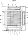
FIG. 1 is a view of an indoor unit of an air conditioner according to an embodiment of the present invention when seen from a lower side. -
FIG. 2 is a cross-sectional view taken along line II-II ofFIG. 1 and is a cross-sectional view of a discharge port of the indoor unit of the air conditioner according to the embodiment of the present invention. -
FIG. 3 is a view from a direction of an arrow III ofFIG. 2 and is a cross-sectional view of the discharge port of the indoor unit of the air conditioner according to the embodiment of the present invention. -
FIG. 4 is a view illustrating an operation of the indoor unit of the air conditioner according to the embodiment of the present invention. -
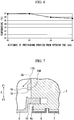
FIG. 5 is a graph illustrating a relationship between a height of a protruding portion from an inner surface and a surface temperature around the discharge port. -
FIG. 6 is a graph illustrating a relationship between a distance of the protruding portion from an opening edge and the surface temperature around the discharge port. -
FIG. 7 is a view illustrating a modified example of the indoor unit of the air conditioner according to the embodiment of the present invention. -
FIG. 8 is a view illustrating an operation of an indoor unit of a conventional air conditioner. - Hereinafter, an
indoor unit 1 of an air conditioner according to an embodiment of the present invention will be described in detail with reference to the drawings. - As illustrated in
FIGS. 1 ,2 and 3 , theindoor unit 1 of an air conditioner includes amain body 2 embedded in a ceiling, asuction port 3 and adischarge port 4 provided in themain body 2, and alouver 5 which opens and closes thedischarge port 4. Theindoor unit 1 of the air conditioner has a substantially square shape when seen from a lower side. - The
main body 2 includes a heat exchanger, a blower fan, and so on which are not illustrated. Themain body 2 adjusts the temperature and humidity of room air RA suctioned through thesuction port 3 and discharges it into a room as conditioned air CA (refer toFIG. 4 ). An outdoor unit (not illustrated) is connected to themain body 2. A refrigerant circulates between theindoor unit 1 of the air conditioner and the outdoor unit. - In the following description, it is assumed that a vertical direction is a flow direction F of the conditioned air CA, an upper side is an upstream side F1 of the conditioned air CA, and a lower side is a downstream side F2 of the conditioned air CA.
- A
panel 7, called a decorative panel or a ceiling panel, is attached to themain body 2. Thepanel 7 is exposed in the room (downward). Thepanel 7 has alouver panel 8 disposed around thelouver 5. - The
suction port 3 for suctioning the room air RA is formed to open downward in a central portion of theindoor unit 1 of the air conditioner. A suction grille 9 at which an air filter (not illustrated) is installed is provided at thesuction port 3. The suction grille 9 has a substantially square shape when seen from below. The four sides of theindoor unit 1 of the air conditioner are parallel to the four sides of the suction grille 9. - The
discharge port 4 is formed to open downward to surround a circumference of thesuction port 3. Thesedischarge ports 4 are provided so that each of thedischarge ports 4 extends along one side to correspond to one side of theindoor unit 1 of the air conditioner. - The
louver 5 and themain body 2 are connected via a rotatingshaft 10 provided at thelouver 5. Thelouver 5 is rotatable between a closed position in which an inside of thedischarge port 4 is closed and an open position in which the inside of thedischarge port 4 is open. Asurface 8a of thelouver panel 8 and asurface 5a of thelouver 5 are flush with each other when thelouver 5 is in the closed position. Each of thelouvers 5 has a rectangular shape having a smaller overall size than thedischarge ports 4. Thelouver 5 is rotated by a driving device such as an actuator (not illustrated). - A cross-sectional shape of the
discharge port 4 seen in the flow direction F of the conditioned air CA is a rectangular shape. In other words, an inner surface of thedischarge port 4 is formed in a rectangular tubular shape and has four surfaces. Thedischarge port 4 includes afirst surface 11 on thesuction port 3 side in a longitudinal direction of thedischarge port 4, asecond surface 12 facing thefirst surface 11, and a pair ofthird surfaces 13 connecting thefirst surface 11 with thesecond surface 12. The pair ofthird surfaces 13 are surfaces orthogonal to the longitudinal direction of thedischarge port 4. - As illustrated in
FIG. 3 , thedischarge port 4 gradually expands toward a downstream side F2 (downward). - The
indoor unit 1 of the air conditioner of the embodiment has a protrudingportion 15 formed on the inner surface of thedischarge port 4 and protruding inside the inner surface. The protrudingportion 15 is positioned at the upstream side F1 (upward) of anopening edge 4a which is an end of the inner surface of thedischarge port 4 on the downstream side F1 of the conditioned air CA. The protrudingportion 15 has a function that the conditioned air CA is removed from the inner surface of thedischarge port 4 by the protrudingportion 15 so as to separate from the openingedge 4a of thedischarge port 4, and thereby room air RA is led into thedischarge port 4 through the openingedge 4a. - The protruding
portion 15 is formed only on athird surface 13 of the inner surface. In other words, the protrudingportion 15 is protruded from the inner surface of thedischarge port 4 which intersects a longitudinal direction of the rectangular shape of the discharge port. - The protruding
portion 15 extends along the openingedge 4a. In other words, the protrudingportion 15 extends in the longitudinal direction of thedischarge port 4. - A cross-sectional shape of the protruding
portion 15 seen from an extending direction of the protrudingportion 15 is substantially square. The protrudingportion 15 includes aparallel surface 16 parallel to the inner surface of thedischarge port 4, anupstream side surface 17 connecting an edge side of theparallel surface 16 on the upstream side F1 with the inner surface of thedischarge port 4, and adownstream side surface 18 connecting an edge side of theparallel surface 16 on the downstream side F2 with the inner surface of thedischarge port 4. Theparallel surface 16 and thedownstream side surface 18 are substantially orthogonal to each other. Theparallel surface 16 and theupstream side surface 17 are substantially orthogonal to each other. - A height H of the protruding
portion 15 from the inner surface (the third surface 13) is 5 mm. - A distance D of the protruding
portion 15 from the openingedge 4a is 40 mm. As will be described later, the height H of the protrudingportion 15 from the inner surface (the third surface 13) and the distance D of the protrudingportion 15 from the openingedge 4a can be appropriately changed. - Next, an operation of the
indoor unit 1 of the air conditioner of the embodiment will be described. - As illustrated in
FIG. 4 , the conditioned air CA (cold air) generated by the heat exchanger and the blower fan (not illustrated) flows along the inner surface of thedischarge port 4. The conditioned air CA which has flowed along the inner surface of thedischarge port 4 from the upstream side F1 separates from the inner surface by colliding with the protrudingportion 15. That is, the flow direction of the conditioned air CA changes, and the conditioned air CA deviates from an opening end of the inner surface. Alternatively, a flow velocity of the conditioned air CA at theopening edge 4a is slowed down. - Therefore, the conditioned air CA flows toward an inside of the opening
edge 4a. Thus, thelouver panel 8 becomes less likely to be cooled by the conditioned air CA. Accordingly, the room air RA flows into the downstream side F2 of the protrudingportion 15. Then, the room air RA that has flowed in and the conditioned air CA are mixed. Since the room air RA is warm, a surface temperature of surroundings (the louver panel 8) of thedischarge port 4 increases. - Here, a size and a position of the protruding
portion 15 will be described. - The inventors performed analysis to examine the size and position of the protruding
portion 15. -
FIG. 5 is a graph illustrating a relationship between the height H (refer toFIG. 2 ) of the protrudingportion 15 from the inner surface and the surface temperature around thedischarge port 4. - As illustrated in
FIG. 5 , it was confirmed that, in a range of the height H of the protrudingportion 15 from the inner surface from 0 mm to 5 mm, the surface temperature gradually increases as the height H increases and reaches 27°C which is an atmospheric temperature at 5 mm. From this result, it was concluded that the height of the protrudingportion 15 from the inner surface is preferably 2 mm to 15 mm. The height H of the protrudingportion 15 from the inner surface can be appropriately changed within this range. -
FIG. 6 is a graph illustrating a relationship between a distance D (refer toFIG. 2 ) of the protrudingportion 15 from the openingedge 4a and the surface temperature around thedischarge port 4. As illustrated inFIG. 6 , it was confirmed that the surface temperature around thedischarge port 4 drops as the protrudingportion 15 moves away from the openingedge 4a. The distance D of the protrudingportion 15 from the openingedge 4a can be appropriately changed. - A width W (refer to
FIG. 3 ) of the protrudingportion 15 of the embodiment is set to about 2/3 of a width of thethird surface 13 to avoid interference when thelouver 5 is in the open position. The protrudingportion 15 may extend from thefirst surface 11 to thesecond surface 12. - According to the embodiment, the conditioned air CA flowing from the upstream side F1 of the protruding
portion 15 is removed from the inner surface of thedischarge port 4 by blowing to the protrudingportion 15. As the conditioned air CA is removed from the openingedge 4a, the room air RA is led into thedischarge port 4 through the openingedge 4a, and thereby a temperature around thedischarge port 4 increases. Accordingly, dew condensation around thedischarge port 4 can be reduced. - Further, since a flow velocity of the conditioned air CA is slowed down at ends of the
discharge port 4 in the longitudinal direction of the rectangular shape thereof, the conditioned air CA intends to flow along a wall surface of the side end of thedischarge port 4, and dew condensation easily occurs on the wall surface. Since the protrudingportion 15 is protruded from the inner surfaces of the discharge port 4 (i.e. the pair of third surfaces 13) which intersects the longitudinal direction of the rectangular shape of thedischarge port 4, the dew condensation on this inner surfaces can be particularly prevented. - Further, in the embodiment, the cross-sectional shape of the protruding
portion 15 is a substantially square shape, but it is not limited thereto. The protrudingportion 15 may have any shape as long as the conditioned air CA flowing on the inner surface of thedischarge port 4 can be separated from the inner surface. - For example, the protruding
portion 15 may have the shape illustrated inFIG. 7 . A protrudingportion 15B of a modified example may include theparallel surface 16 parallel to the inner surface of thedischarge port 4, adownstream side surface 18 positioned between a downstream side end of theparallel surface 16 and the inner surface of thedischarge port 4, and anupstream side surface 17B positioned between an upstream side end of theparallel surface 16 and the inner surface of thedischarge port 4, and theupstream side surface 17B may be inclined with respect to the inner surface of thedischarge port 4 toward a downstream side of the conditioned air CA as close to a top of the protruding portion. - That is, the
upstream side surface 17B and the inner surface are not orthogonal to each other, and the conditioned air CA flowing along the inner surface flows smoothly on theupstream side surface 17B and then separates from the inner surface. By adopting such a shape, it is possible to separate the conditioned airflow CA from the inner surface without disturbing a flow thereof. - Although an embodiment of the present invention has been described in detail with reference to the drawings, the specific constitution is not limited to this embodiment, and design changes or the like within the scope not deviating from the gist of the present invention are included.
- Further, in the above-described embodiment, the protruding
portion 15 is provided only on the pair ofthird surfaces 13 of the inner surfaces, but the invention is not limited thereto, and the protrudingportion 15 may be provided on the entire circumference of the inner surfaces. - Further, the
indoor unit 1 of the air conditioner in the above-described embodiment is the embedded type, but the present invention is not limited thereto and may also be applicable to a hanging type indoor unit. - In addition, the cross-sectional shape of the
discharge port 4 is not limited to a rectangular shape but may also be a circular shape or a polygonal shape. -
- 1 Indoor unit of air conditioner
- 2 Main body
- 3 Suction port
- 4 Discharge port
- 4a Opening edge
- 5 Louver
- 7 Panel
- 8 Louver panel
- 9 Suction grille
- 10 Rotating shaft
- 11 First surface
- 12 Second surface
- 13 Third surface
- 15 Protruding portion
- 16 Parallel surface
- 17, 17B Upstream side surface
- 18 Downstream side surface
- CA conditioned air
- F Flow direction
- F1 Upstream side
- F2 Downstream side
- RA Room air
Claims (4)
- An indoor unit (1) of an air conditioner, comprising:a main body (2);a discharge port (4) formed on the main body and is configured to discharge conditioned air (CA) from the main body; anda protruding portion (15) formed on an inner surface of the discharge port so as to be positioned at an upstream side (F1) of the conditioned air with respect to an opening edge (4a) of the discharge port which is an end section of the discharge port at a downstream side of the conditioned air,wherein the protruding portion is configured to remove the conditioned air from the inner surface of the discharge port so as to separate it from the opening edge of the discharge port, and thereby room air is led into the discharge port through the opening edge thereof.
- The indoor unit (1) according to of claim 1, wherein a cross-sectional shape of the discharge port (4) is a rectangular shape when seen in a flow direction of the conditioned air, and
the protruding portion (15) is protruded from the inner surface of the discharge port which intersects a longitudinal direction of the rectangular shape of the discharge port. - The indoor unit (1) according to of claim 1 or 2, wherein a height of the protruding portion (15) from the inner surface of the discharge port (4) is 2 mm to 15 mm.
- The indoor unit (1) according to any one of claims 1 to 3, wherein the protruding portion (15) includes a parallel surface (16) parallel to the inner surface of the discharge port (4), a downstream side surface (18) positioned between a downstream side end of the parallel surface and the inner surface of the discharge port, and an upstream side surface (17) positioned between an upstream side end of the parallel surface and the inner surface of the discharge port, and
the upstream side surface is inclined with respect to the inner surface of the discharge port toward a downstream side of the conditioned air as close to a top of the protruding portion.
Applications Claiming Priority (1)
| Application Number | Priority Date | Filing Date | Title |
|---|---|---|---|
| JP2017089842A JP2018189261A (en) | 2017-04-28 | 2017-04-28 | Air conditioner indoor unit |
Publications (1)
| Publication Number | Publication Date |
|---|---|
| EP3396268A1 true EP3396268A1 (en) | 2018-10-31 |
Family
ID=62067550
Family Applications (1)
| Application Number | Title | Priority Date | Filing Date |
|---|---|---|---|
| EP18169621.2A Withdrawn EP3396268A1 (en) | 2017-04-28 | 2018-04-26 | Indoor unit of air conditioner |
Country Status (2)
| Country | Link |
|---|---|
| EP (1) | EP3396268A1 (en) |
| JP (1) | JP2018189261A (en) |
Citations (6)
| Publication number | Priority date | Publication date | Assignee | Title |
|---|---|---|---|---|
| JPS59161636A (en) * | 1983-03-07 | 1984-09-12 | Matsushita Electric Ind Co Ltd | Flowing direction controlling device |
| GB2293447A (en) * | 1994-09-26 | 1996-03-27 | Mitsubishi Electric Corp | A device for directing the flow of forced air |
| WO2011040519A1 (en) * | 2009-09-30 | 2011-04-07 | ダイキン工業株式会社 | Air conditioning device |
| JP2012251676A (en) | 2011-05-31 | 2012-12-20 | Daikin Industries Ltd | Indoor unit for air conditioner |
| WO2016067671A1 (en) * | 2014-10-31 | 2016-05-06 | 豊和化成株式会社 | Air discharge device |
| EP3017977A1 (en) * | 2014-10-31 | 2016-05-11 | Howa Plastics Co., Ltd. | Air blowing device |
-
2017
- 2017-04-28 JP JP2017089842A patent/JP2018189261A/en active Pending
-
2018
- 2018-04-26 EP EP18169621.2A patent/EP3396268A1/en not_active Withdrawn
Patent Citations (6)
| Publication number | Priority date | Publication date | Assignee | Title |
|---|---|---|---|---|
| JPS59161636A (en) * | 1983-03-07 | 1984-09-12 | Matsushita Electric Ind Co Ltd | Flowing direction controlling device |
| GB2293447A (en) * | 1994-09-26 | 1996-03-27 | Mitsubishi Electric Corp | A device for directing the flow of forced air |
| WO2011040519A1 (en) * | 2009-09-30 | 2011-04-07 | ダイキン工業株式会社 | Air conditioning device |
| JP2012251676A (en) | 2011-05-31 | 2012-12-20 | Daikin Industries Ltd | Indoor unit for air conditioner |
| WO2016067671A1 (en) * | 2014-10-31 | 2016-05-06 | 豊和化成株式会社 | Air discharge device |
| EP3017977A1 (en) * | 2014-10-31 | 2016-05-11 | Howa Plastics Co., Ltd. | Air blowing device |
Also Published As
| Publication number | Publication date |
|---|---|
| JP2018189261A (en) | 2018-11-29 |
Similar Documents
| Publication | Publication Date | Title |
|---|---|---|
| US10386079B2 (en) | Air conditioner | |
| EP2498019B1 (en) | Indoor unit for air conditioner | |
| CN107278255B (en) | Indoor unit of air conditioner | |
| JP4544364B1 (en) | Air conditioner | |
| JP4107334B2 (en) | Air conditioner | |
| EP3070410A1 (en) | Outdoor unit of air conditioner | |
| WO2015111281A1 (en) | Air conditioner | |
| JP2008275231A (en) | Air conditioner | |
| JP6429204B2 (en) | Air conditioner | |
| JP6139669B2 (en) | Air conditioner | |
| WO2016063397A1 (en) | Air conditioner | |
| WO2015155855A1 (en) | Air conditioner | |
| JP2003097821A (en) | Air conditioner | |
| JP5860752B2 (en) | Air conditioner | |
| CN108496045A (en) | Indoor unit of air conditioner | |
| JP2008045780A (en) | Indoor unit of air conditioner | |
| JP2018179384A (en) | Indoor unit of air conditioner | |
| JP2008292029A (en) | Air conditioner | |
| KR101448304B1 (en) | A ceiling-mounted type air conditioner | |
| JP6340694B2 (en) | Blower | |
| WO2015104791A1 (en) | Air-conditioning device | |
| JP2018189261A (en) | Air conditioner indoor unit | |
| KR20160098885A (en) | Air conditioner | |
| JP2014129927A (en) | Ceiling installation indoor unit | |
| JP2007315670A (en) | Indoor unit of air conditioner |
Legal Events
| Date | Code | Title | Description |
|---|---|---|---|
| PUAI | Public reference made under article 153(3) epc to a published international application that has entered the european phase |
Free format text: ORIGINAL CODE: 0009012 |
|
| STAA | Information on the status of an ep patent application or granted ep patent |
Free format text: STATUS: THE APPLICATION HAS BEEN PUBLISHED |
|
| AK | Designated contracting states |
Kind code of ref document: A1 Designated state(s): AL AT BE BG CH CY CZ DE DK EE ES FI FR GB GR HR HU IE IS IT LI LT LU LV MC MK MT NL NO PL PT RO RS SE SI SK SM TR |
|
| AX | Request for extension of the european patent |
Extension state: BA ME |
|
| STAA | Information on the status of an ep patent application or granted ep patent |
Free format text: STATUS: REQUEST FOR EXAMINATION WAS MADE |
|
| 17P | Request for examination filed |
Effective date: 20190425 |
|
| RBV | Designated contracting states (corrected) |
Designated state(s): AL AT BE BG CH CY CZ DE DK EE ES FI FR GB GR HR HU IE IS IT LI LT LU LV MC MK MT NL NO PL PT RO RS SE SI SK SM TR |
|
| STAA | Information on the status of an ep patent application or granted ep patent |
Free format text: STATUS: EXAMINATION IS IN PROGRESS |
|
| 17Q | First examination report despatched |
Effective date: 20190626 |
|
| STAA | Information on the status of an ep patent application or granted ep patent |
Free format text: STATUS: THE APPLICATION HAS BEEN WITHDRAWN |
|
| 18W | Application withdrawn |
Effective date: 20191016 |