EP3396263A1 - Multisensor unit, an arrangement and a method for managing the indoor climate conditions of a room or of a zone - Google Patents
Multisensor unit, an arrangement and a method for managing the indoor climate conditions of a room or of a zone Download PDFInfo
- Publication number
- EP3396263A1 EP3396263A1 EP18167889.7A EP18167889A EP3396263A1 EP 3396263 A1 EP3396263 A1 EP 3396263A1 EP 18167889 A EP18167889 A EP 18167889A EP 3396263 A1 EP3396263 A1 EP 3396263A1
- Authority
- EP
- European Patent Office
- Prior art keywords
- zone
- room
- unit
- indoor climate
- multisensor
- Prior art date
- Legal status (The legal status is an assumption and is not a legal conclusion. Google has not performed a legal analysis and makes no representation as to the accuracy of the status listed.)
- Granted
Links
Images



Classifications
-
- G—PHYSICS
- G05—CONTROLLING; REGULATING
- G05D—SYSTEMS FOR CONTROLLING OR REGULATING NON-ELECTRIC VARIABLES
- G05D23/00—Control of temperature
- G05D23/01—Control of temperature without auxiliary power
- G05D23/13—Control of temperature without auxiliary power by varying the mixing ratio of two fluids having different temperatures
- G05D23/1306—Control of temperature without auxiliary power by varying the mixing ratio of two fluids having different temperatures for liquids
- G05D23/132—Control of temperature without auxiliary power by varying the mixing ratio of two fluids having different temperatures for liquids with temperature sensing element
-
- F—MECHANICAL ENGINEERING; LIGHTING; HEATING; WEAPONS; BLASTING
- F24—HEATING; RANGES; VENTILATING
- F24F—AIR-CONDITIONING; AIR-HUMIDIFICATION; VENTILATION; USE OF AIR CURRENTS FOR SCREENING
- F24F11/00—Control or safety arrangements
- F24F11/30—Control or safety arrangements for purposes related to the operation of the system, e.g. for safety or monitoring
-
- B—PERFORMING OPERATIONS; TRANSPORTING
- B60—VEHICLES IN GENERAL
- B60H—ARRANGEMENTS OF HEATING, COOLING, VENTILATING OR OTHER AIR-TREATING DEVICES SPECIALLY ADAPTED FOR PASSENGER OR GOODS SPACES OF VEHICLES
- B60H1/00—Heating, cooling or ventilating devices
- B60H1/00642—Control systems or circuits; Control members or indication devices for heating, cooling or ventilating devices
- B60H1/00735—Control systems or circuits characterised by their input, i.e. by the detection, measurement or calculation of particular conditions, e.g. signal treatment, dynamic models
-
- F—MECHANICAL ENGINEERING; LIGHTING; HEATING; WEAPONS; BLASTING
- F24—HEATING; RANGES; VENTILATING
- F24F—AIR-CONDITIONING; AIR-HUMIDIFICATION; VENTILATION; USE OF AIR CURRENTS FOR SCREENING
- F24F11/00—Control or safety arrangements
- F24F11/89—Arrangement or mounting of control or safety devices
-
- G—PHYSICS
- G01—MEASURING; TESTING
- G01K—MEASURING TEMPERATURE; MEASURING QUANTITY OF HEAT; THERMALLY-SENSITIVE ELEMENTS NOT OTHERWISE PROVIDED FOR
- G01K1/00—Details of thermometers not specially adapted for particular types of thermometer
- G01K1/02—Means for indicating or recording specially adapted for thermometers
- G01K1/04—Scales
- G01K1/045—Scales temperature indication combined with the indication of another variable
-
- G—PHYSICS
- G01—MEASURING; TESTING
- G01K—MEASURING TEMPERATURE; MEASURING QUANTITY OF HEAT; THERMALLY-SENSITIVE ELEMENTS NOT OTHERWISE PROVIDED FOR
- G01K1/00—Details of thermometers not specially adapted for particular types of thermometer
- G01K1/14—Supports; Fastening devices; Arrangements for mounting thermometers in particular locations
-
- G—PHYSICS
- G05—CONTROLLING; REGULATING
- G05B—CONTROL OR REGULATING SYSTEMS IN GENERAL; FUNCTIONAL ELEMENTS OF SUCH SYSTEMS; MONITORING OR TESTING ARRANGEMENTS FOR SUCH SYSTEMS OR ELEMENTS
- G05B15/00—Systems controlled by a computer
-
- G—PHYSICS
- G05—CONTROLLING; REGULATING
- G05D—SYSTEMS FOR CONTROLLING OR REGULATING NON-ELECTRIC VARIABLES
- G05D22/00—Control of humidity
- G05D22/02—Control of humidity characterised by the use of electric means
-
- H—ELECTRICITY
- H04—ELECTRIC COMMUNICATION TECHNIQUE
- H04L—TRANSMISSION OF DIGITAL INFORMATION, e.g. TELEGRAPHIC COMMUNICATION
- H04L12/00—Data switching networks
- H04L12/28—Data switching networks characterised by path configuration, e.g. LAN [Local Area Networks] or WAN [Wide Area Networks]
- H04L12/2803—Home automation networks
-
- H—ELECTRICITY
- H04—ELECTRIC COMMUNICATION TECHNIQUE
- H04N—PICTORIAL COMMUNICATION, e.g. TELEVISION
- H04N5/00—Details of television systems
- H04N5/30—Transforming light or analogous information into electric information
- H04N5/33—Transforming infrared radiation
-
- F—MECHANICAL ENGINEERING; LIGHTING; HEATING; WEAPONS; BLASTING
- F24—HEATING; RANGES; VENTILATING
- F24F—AIR-CONDITIONING; AIR-HUMIDIFICATION; VENTILATION; USE OF AIR CURRENTS FOR SCREENING
- F24F2110/00—Control inputs relating to air properties
- F24F2110/10—Temperature
-
- F—MECHANICAL ENGINEERING; LIGHTING; HEATING; WEAPONS; BLASTING
- F24—HEATING; RANGES; VENTILATING
- F24F—AIR-CONDITIONING; AIR-HUMIDIFICATION; VENTILATION; USE OF AIR CURRENTS FOR SCREENING
- F24F2110/00—Control inputs relating to air properties
- F24F2110/20—Humidity
-
- F—MECHANICAL ENGINEERING; LIGHTING; HEATING; WEAPONS; BLASTING
- F24—HEATING; RANGES; VENTILATING
- F24F—AIR-CONDITIONING; AIR-HUMIDIFICATION; VENTILATION; USE OF AIR CURRENTS FOR SCREENING
- F24F2110/00—Control inputs relating to air properties
- F24F2110/50—Air quality properties
-
- F—MECHANICAL ENGINEERING; LIGHTING; HEATING; WEAPONS; BLASTING
- F24—HEATING; RANGES; VENTILATING
- F24F—AIR-CONDITIONING; AIR-HUMIDIFICATION; VENTILATION; USE OF AIR CURRENTS FOR SCREENING
- F24F2110/00—Control inputs relating to air properties
- F24F2110/50—Air quality properties
- F24F2110/64—Airborne particle content
-
- F—MECHANICAL ENGINEERING; LIGHTING; HEATING; WEAPONS; BLASTING
- F24—HEATING; RANGES; VENTILATING
- F24F—AIR-CONDITIONING; AIR-HUMIDIFICATION; VENTILATION; USE OF AIR CURRENTS FOR SCREENING
- F24F2110/00—Control inputs relating to air properties
- F24F2110/50—Air quality properties
- F24F2110/65—Concentration of specific substances or contaminants
- F24F2110/70—Carbon dioxide
-
- F—MECHANICAL ENGINEERING; LIGHTING; HEATING; WEAPONS; BLASTING
- F24—HEATING; RANGES; VENTILATING
- F24F—AIR-CONDITIONING; AIR-HUMIDIFICATION; VENTILATION; USE OF AIR CURRENTS FOR SCREENING
- F24F2110/00—Control inputs relating to air properties
- F24F2110/50—Air quality properties
- F24F2110/65—Concentration of specific substances or contaminants
- F24F2110/76—Oxygen
-
- F—MECHANICAL ENGINEERING; LIGHTING; HEATING; WEAPONS; BLASTING
- F24—HEATING; RANGES; VENTILATING
- F24F—AIR-CONDITIONING; AIR-HUMIDIFICATION; VENTILATION; USE OF AIR CURRENTS FOR SCREENING
- F24F2120/00—Control inputs relating to users or occupants
- F24F2120/10—Occupancy
-
- F—MECHANICAL ENGINEERING; LIGHTING; HEATING; WEAPONS; BLASTING
- F24—HEATING; RANGES; VENTILATING
- F24F—AIR-CONDITIONING; AIR-HUMIDIFICATION; VENTILATION; USE OF AIR CURRENTS FOR SCREENING
- F24F2120/00—Control inputs relating to users or occupants
- F24F2120/10—Occupancy
- F24F2120/12—Position of occupants
-
- Y—GENERAL TAGGING OF NEW TECHNOLOGICAL DEVELOPMENTS; GENERAL TAGGING OF CROSS-SECTIONAL TECHNOLOGIES SPANNING OVER SEVERAL SECTIONS OF THE IPC; TECHNICAL SUBJECTS COVERED BY FORMER USPC CROSS-REFERENCE ART COLLECTIONS [XRACs] AND DIGESTS
- Y02—TECHNOLOGIES OR APPLICATIONS FOR MITIGATION OR ADAPTATION AGAINST CLIMATE CHANGE
- Y02B—CLIMATE CHANGE MITIGATION TECHNOLOGIES RELATED TO BUILDINGS, e.g. HOUSING, HOUSE APPLIANCES OR RELATED END-USER APPLICATIONS
- Y02B30/00—Energy efficient heating, ventilation or air conditioning [HVAC]
- Y02B30/70—Efficient control or regulation technologies, e.g. for control of refrigerant flow, motor or heating
Definitions
- the invention relates to the field of building and construction technologies in general and to the field of building indoor climate management, and more particularly to a multisensor unit, an arrangement and a method for managing the indoor climate conditions of a room or of a zone.
- the indoor climate management is typically handled with different systems in the same building.
- a heating system is used to bring heat and warming to the indoor premises.
- the building In the summer and during warm/hot weather conditions the building typically has a cooling system or an air conditioning system for providing cool air to the premises of the building.
- a separate lighting system providing light to the premises.
- the indoor climate conditions of a room or a zone typically depend on the functioning or all the above mentioned different indoor climate management systems, i.e. a heating system, a cooling system, an air conditioning system, an air ventilation system a lighting system.
- Each of the said indoor climate management systems typically has control system with relevant sensor arrangements in place.
- the object of the invention is to introduce a new solution for managing the indoor climate conditions of a room or of a zone, which would provide a simpler design and bring savings.
- a new multisensor unit for managing the indoor climate conditions of a room or of a zone, which multisensor unit is attached to the ceiling of said room or said zone, and which multisensor unit comprises a temperature detector for detecting the temperature in said room or said zone, a thermal imaging sensor arranged to detect the presence and/or position of human in said room or in said zone and/or the number of persons present in said room or in said zone, and to detect the temperatures of the ceiling, wall, floor and/or a window in said room or in said zone and the skin temperature of human in said room or in said zone, and an at least one air quality detector for detecting parameters relating to the air condition/air quality and/or to the indoor climate conditions of said room or said zone; which multisensor unit is adapted to provide measurement data for one or more parameters relating to the air condition/air quality and/or to the indoor climate conditions of said room or of said zone.
- said thermal imaging sensor is an infrared sensor.
- said thermal imaging sensor is arranged to measure temperatures within its detection range in said room or in said zone.
- said detection range of said thermal imaging sensor is arranged to cover the entire indoor space of said room or of said zone.
- said thermal imaging sensor is arranged to detect when said room or in said zone is unoccupied.
- said thermal imaging sensor is arranged to detect and provide information on the temperatures of said window for the determination of the outside weather conditions and for the determination whether the curtains, blinds or awnings are covering said window.
- said thermal imaging sensor is arranged to detect the temperature gradient in said room or in said zone.
- said temperature detector is a thermocouple type temperature detector or a thermopile type temperature detector.
- said one or more parameters relating to the air condition/air quality and/or to the indoor climate conditions of said room or of said zone comprise parameters relating e.g. to oxygen content (O 2 ), to carbon dioxide content (CO 2 ), to dust particle content, to air purity or to air humidity.
- a new arrangement for managing the indoor climate conditions of a room or of a zone which arrangement comprises a multisensor unit attached to the ceiling of said room or said zone, and which multisensor unit comprises a temperature detector for detecting the temperature in said room or said zone, a thermal imaging sensor arranged to detect the presence and/or position of human in said room or in said zone and/or the number of persons present in said room or in said zone, and to detect the temperatures of the ceiling, wall, floor and/or a window in said room or in said zone and the skin temperature of human in said room or in said zone, and an at least one air quality detector for detecting parameters relating to the air condition/air quality and/or to the indoor climate conditions of said room or said zone, which multisensor unit is adapted to provide measurement data for one or more parameters relating to the air condition/air quality and/or to the indoor climate conditions of said room or of said zone, a control unit, and indoor climate conditioning units.
- said control unit is arranged to receive said measurement data for one or more parameters relating to the air condition/air quality and/or to the indoor climate conditions of said room or of said zone from the multisensor unit.
- said control unit is adapted to control said indoor climate conditioning units for managing the indoor climate conditions of said room or of said zone.
- said indoor climate conditioning units comprise a heating unit, a cooling/air conditioning unit, an air ventilation unit and/or a lighting unit.
- a new method for managing the indoor climate conditions of a room or of a zone comprises the steps of: detecting the temperature in said room or said zone with a temperature detector of a multisensor unit, which multisensor unit is attached to the ceiling of said room or said zone, detecting parameters relating to the air condition/air quality and/or to the indoor climate conditions of said room or said zone with an at least one air quality detector of said multisensor unit, detecting the presence and/or position of human in said room or said zone and/or the number of persons present in said room or in said zone by a thermal imaging sensor of said multisensor unit, detecting the temperatures of the ceiling, wall, floor and/or a window in said room or in said zone by a thermal imaging sensor of said multisensor unit, detecting the skin temperature of human in said room or in said zone by a thermal imaging sensor of said multisensor unit, providing measurement data for one or more parameters relating to the air condition/air quality and/or to the indoor climate conditions of said room or of said zone by said multisensor unit, and performing
- Figure 1 illustrates a sectional view depicting a positional relation between a room or a zone and a multisensor unit according to one embodiment of the present invention.
- the multisensor unit 1 according to the presented embodiment is attached to the ceiling 2 of a room or a zone.
- the multisensor unit 1 comprises a temperature detector 3 for detecting the temperature in the room or the zone and a thermal imaging sensor 4 for detecting the presence and/or position of human in the room or in the zone.
- the temperature detector 3 may e.g. be a thermocouple type temperature detector 3 or a thermopile type temperature detector 3.
- the thermal imaging sensor 4 according to the present invention may e.g. be an infrared sensor 4.
- the multisensor unit 1 comprises an at least one air quality detector for detecting parameters relating to the air condition/air quality and/or to the indoor climate conditions of the room or the zone.
- the said parameters relating to the air condition/air quality may comprise parameters relating e.g. to oxygen content (O 2 ), to carbon dioxide content (CO 2 ), to dust particle content, to air purity or to air humidity.
- the thermal imaging sensor 4 of the multisensor unit 1 is arranged to measure temperatures within its detection range in a room or in a zone.
- the said detection range of said thermal imaging sensor 4 may comprise a plurality of ranges 21-28 arranged perpendicularly to a first axial direction within its detection range in a room or in a zone.
- the detection range of said thermal imaging sensor 4 may allow the thermal imaging sensor 4 to detect temperatures of the ceiling 2 as well as temperatures of the wall 5 and the temperatures of the floor 6 in a room or in a zone.
- the thermal imaging sensor 4 of the multisensor unit 1 according to the presented embodiment is arranged to detect the presence and/or position of human 7 in the room or in the zone.
- the thermal imaging sensor 4 of the multisensor unit 1 according to the presented embodiment may also detect the temperature gradient in the room or in the zone. Furthermore, said thermal imaging sensor 4 may detect the skin temperature of human 7 in the room or in the zone. Furthermore, the thermal imaging sensor 4 of the multisensor unit 1 according to the presented embodiment may detect the number of persons present in the room or in the zone. Said thermal imaging sensor 4 may also detect when the room or the zone is unoccupied.
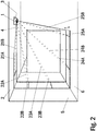
- Figure 2 illustrates a perspective view depicting a relation between an indoor space of a room/zone and a sensing area of a thermal imaging sensor of a multisensor unit according to one embodiment of the present invention.
- the multisensor unit 1 according to the presented embodiment is attached to the ceiling 2 of a room or a zone.
- the multisensor unit 1 comprises a temperature detector 3 for detecting the temperature in the room or the zone, a thermal imaging sensor 4 for detecting the presence and/or position of human in the room or in the zone and an at least one air quality detector for detecting parameters relating to the air condition/air quality and/or to the indoor climate conditions of the room or the zone.
- the thermal imaging sensor 4 of the multisensor unit 1 is arranged to measure temperatures within its detection range in a room or in a zone.
- the said detection range of said thermal imaging sensor 4 may comprise a plurality of ranges arranged perpendicularly to a first axial direction within its detection range in a room or in a zone.
- the detection range of said thermal imaging sensor 4 may allow the thermal imaging sensor 4 to detect temperatures of the ceiling 2 as well as temperatures of the wall 5 and the temperatures of the floor 6 in a room or in a zone.
- said detection range of said thermal imaging sensor 4 may comprise a plurality of ranges 21A-21B, 22A-22B, 23A-23B, 24A-24B, 25A-25B arranged perpendicularly to a first axial direction and to a second axial direction within its detection range in a room or in a zone.
- the detection range of said thermal imaging sensor 4 is arranged to cover the entire indoor space of a room or of a zone.
- the multisensor unit 1 according to the present invention may be integrated to a ceiling element of the room or of the zone.
- FIG. 3 illustrates a diagrammatic representation depicting another embodiment of an installation of a multisensor unit according to the present invention.
- the multisensor unit 1 according to the presented embodiment is attached to the ceiling 2 of a room or a zone.
- the multisensor unit 1 according to the presented embodiment is attached to the ceiling 2 of a room or a zone.
- the multisensor unit 1 comprises a temperature detector 3 for detecting the temperature in the room or the zone, a thermal imaging sensor 4 for detecting the presence and/or position of human in the room or in the zone and an at least one air quality detector for detecting parameters relating to the air condition/air quality and/or to the indoor climate conditions of the room or the zone.
- the temperature detector 3 may e.g. be a thermocouple type temperature detector 3 or a thermopile type temperature detector 3.
- the thermal imaging sensor 4 according to the present invention may e.g. be an infrared sensor 4.
- the multisensor unit 1 comprises an at least one air quality detector for detecting parameters relating to the air condition/air quality and/or to the indoor climate conditions of the room or the zone.
- the said parameters relating to the air condition/air quality may comprise parameters relating e.g. to oxygen content (O 2 ), to carbon dioxide content (CO 2 ), to dust particle content or to air humidity.
- the thermal imaging sensor 4 of the multisensor unit 1 is arranged to measure temperatures within its detection range in a room or in a zone and to detect the presence and/or position of human 8, 9 in the room or in the zone.
- the detection range of said thermal imaging sensor 4 may allow the thermal imaging sensor 4 to detect temperatures of the ceiling 2 as well as temperatures of the wall 5 and the temperatures of the floor 6 in a room or in a zone.
- the thermal imaging sensor 4 of the multisensor unit 1 is also arranged to detect the temperatures of a window 10 on the wall 5 in a room or in a zone.
- the multisensor unit 1 according to the presented invention may be arranged to detect and provide information on the temperatures of a window 10 for the determination of the outside weather conditions and for the determination, whether the curtains, blinds or awnings are covering the window 10.
- said multisensor unit 1 may be arranged to detect and provide information on the illumination level in a room or in a zone.
- Figure 4 illustrates an arrangement for managing the indoor climate conditions of a room or of a zone according to one embodiment of the present invention.
- the arrangement for managing the indoor climate conditions of a room or of a zone according to one embodiment of the present invention comprises a multisensor unit 1 attached to the ceiling of a room or a zone, and a control unit 11 for controlling the indoor climate conditions of said room or of said zone.
- the arrangement for managing the indoor climate conditions of a room or of a zone according to the presented embodiment comprises indoor climate conditioning units 21-24 for managing the indoor climate conditions of said room or of said zone.
- Said indoor climate conditioning units 21-24 may e.g. comprise a heating unit 21, a cooling/air conditioning unit 22, an air ventilation unit 23 and a lighting unit 24.
- the multisensor unit 1 is adapted to provide measurement data for one or more parameters relating to the air condition/air quality and/or to the indoor climate conditions of the room or of the zone to the control unit 11 for the management of the indoor climate conditions of the room or of the zone.
- the control unit 11 is arranged to receive said measurement data for one or more parameters relating to the air condition/air quality and/or to the indoor climate conditions of said room or of said zone from the multisensor unit 1 and adapted to control said indoor climate conditioning units 21-24 for managing the indoor climate conditions of said room or of said zone.
- the control unit 11 is adapted to control the heating unit 21, the cooling/air conditioning unit 22, the air ventilation unit 23 and the lighting unit 24.
- Figure 5 illustrates a method for managing the indoor climate conditions of a room or of a zone according to one embodiment of the present invention.
- the temperature in the room or the zone is detected 31 by the temperature detector 3 of the multisensor unit 1.
- parameters relating to the air condition/air quality and/or to the indoor climate conditions of the room or of the zone are detected 32 by said at least one air quality detector of said multisensor unit 1.
- the said parameters relating to the air condition/air quality may comprise parameters relating e.g. to oxygen content (O 2 ), to carbon dioxide content (CO 2 ), to dust particle content or to air humidity.
- the presence and/or position of human in the room or in the zone is detected 33 by the thermal imaging sensor 4 of the multisensor unit 1.
- the multisensor unit 1 may or may not continue 34 with another measurement and repeat steps 31-33.
- the multisensor unit 1 may be instructed to or may be automated to carry out multiple measurements.
- the multisensor unit 1 may e.g. change the scanning pattern and/or scanning frequency of said thermal imaging sensor 4 in the step of detecting 32 the presence and/or position of human in the room or in the zone.
- the multisensor unit 1 After carrying out enough measurements by repeating the steps 31-33, the multisensor unit 1 provides 35 measurement data for one or more parameters to the control unit 11 for determining the need for condition management of a room or of a zone. After receiving one or more parameters for the determination of the need for condition management of the room or of the zone the control unit 11 performs 36 condition management actions and controls the heating unit 21, a cooling/air conditioning unit 22, an air ventilation unit 23 and/or the lighting unit 24 according to said condition management actions.
Landscapes
- Engineering & Computer Science (AREA)
- Physics & Mathematics (AREA)
- General Physics & Mathematics (AREA)
- Automation & Control Theory (AREA)
- General Engineering & Computer Science (AREA)
- Mechanical Engineering (AREA)
- Chemical & Material Sciences (AREA)
- Combustion & Propulsion (AREA)
- Signal Processing (AREA)
- Computer Networks & Wireless Communication (AREA)
- Multimedia (AREA)
- Thermal Sciences (AREA)
- Air Conditioning Control Device (AREA)
Abstract
Description
- The invention relates to the field of building and construction technologies in general and to the field of building indoor climate management, and more particularly to a multisensor unit, an arrangement and a method for managing the indoor climate conditions of a room or of a zone.
- In the field of building and construction technologies, the indoor climate management is typically handled with different systems in the same building. In the winter and during the cold season a heating system is used to bring heat and warming to the indoor premises. In the summer and during warm/hot weather conditions the building typically has a cooling system or an air conditioning system for providing cool air to the premises of the building. There also can be a separate air ventilation system in the building providing for suitable fresh air to the premises. Also typically, in a building there is a separate lighting system providing light to the premises.
- The indoor climate conditions of a room or a zone typically depend on the functioning or all the above mentioned different indoor climate management systems, i.e. a heating system, a cooling system, an air conditioning system, an air ventilation system a lighting system. Each of the said indoor climate management systems typically has control system with relevant sensor arrangements in place.
- In prior art, there has been some arrangements where the different indoor climate management systems are somehow coordinated to bring savings and better coordination for the indoor climate management. However, typically each system typically relies on its own sensors for providing the climate management control.
- The object of the invention is to introduce a new solution for managing the indoor climate conditions of a room or of a zone, which would provide a simpler design and bring savings. There is a demand in the market for a more straightforward solution for indoor climate condition management of a room or of a zone in a building.
- It is brought forward a new multisensor unit for managing the indoor climate conditions of a room or of a zone, which multisensor unit is attached to the ceiling of said room or said zone, and which multisensor unit comprises a temperature detector for detecting the temperature in said room or said zone, a thermal imaging sensor arranged to detect the presence and/or position of human in said room or in said zone and/or the number of persons present in said room or in said zone, and to detect the temperatures of the ceiling, wall, floor and/or a window in said room or in said zone and the skin temperature of human in said room or in said zone, and an at least one air quality detector for detecting parameters relating to the air condition/air quality and/or to the indoor climate conditions of said room or said zone; which multisensor unit is adapted to provide measurement data for one or more parameters relating to the air condition/air quality and/or to the indoor climate conditions of said room or of said zone. Hereby, one or more of the above-mentioned advantages and/or objectives are achieved. These advantages and/or objectives are further facilitated with the additional preferred features and/or steps described in the following.
- In a preferred embodiment of said multisensor unit, said thermal imaging sensor is an infrared sensor.
- In a preferred embodiment of said multisensor unit, said thermal imaging sensor is arranged to measure temperatures within its detection range in said room or in said zone.
- In a preferred embodiment of said multisensor unit, said detection range of said thermal imaging sensor is arranged to cover the entire indoor space of said room or of said zone.
- In a preferred embodiment of said multisensor unit, said thermal imaging sensor is arranged to detect when said room or in said zone is unoccupied.
- In a preferred embodiment of said multisensor unit, said thermal imaging sensor is arranged to detect and provide information on the temperatures of said window for the determination of the outside weather conditions and for the determination whether the curtains, blinds or awnings are covering said window.
- In a preferred embodiment of said multisensor unit, said thermal imaging sensor is arranged to detect the temperature gradient in said room or in said zone.
- In a preferred embodiment of said multisensor unit, said temperature detector is a thermocouple type temperature detector or a thermopile type temperature detector.
- In a preferred embodiment of said multisensor unit, said one or more parameters relating to the air condition/air quality and/or to the indoor climate conditions of said room or of said zone comprise parameters relating e.g. to oxygen content (O2), to carbon dioxide content (CO2), to dust particle content, to air purity or to air humidity.
- It is also brought forward a new arrangement for managing the indoor climate conditions of a room or of a zone, which arrangement comprises a multisensor unit attached to the ceiling of said room or said zone, and which multisensor unit comprises a temperature detector for detecting the temperature in said room or said zone, a thermal imaging sensor arranged to detect the presence and/or position of human in said room or in said zone and/or the number of persons present in said room or in said zone, and to detect the temperatures of the ceiling, wall, floor and/or a window in said room or in said zone and the skin temperature of human in said room or in said zone, and an at least one air quality detector for detecting parameters relating to the air condition/air quality and/or to the indoor climate conditions of said room or said zone, which multisensor unit is adapted to provide measurement data for one or more parameters relating to the air condition/air quality and/or to the indoor climate conditions of said room or of said zone, a control unit, and indoor climate conditioning units.
- In a preferred embodiment of said arrangement, said control unit is arranged to receive said measurement data for one or more parameters relating to the air condition/air quality and/or to the indoor climate conditions of said room or of said zone from the multisensor unit.
- In a preferred embodiment of said arrangement, said control unit is adapted to control said indoor climate conditioning units for managing the indoor climate conditions of said room or of said zone.
- In a preferred embodiment of said arrangement, said indoor climate conditioning units comprise a heating unit, a cooling/air conditioning unit, an air ventilation unit and/or a lighting unit.
- It is also brought forward a new method for managing the indoor climate conditions of a room or of a zone, which method comprises the steps of: detecting the temperature in said room or said zone with a temperature detector of a multisensor unit, which multisensor unit is attached to the ceiling of said room or said zone, detecting parameters relating to the air condition/air quality and/or to the indoor climate conditions of said room or said zone with an at least one air quality detector of said multisensor unit, detecting the presence and/or position of human in said room or said zone and/or the number of persons present in said room or in said zone by a thermal imaging sensor of said multisensor unit, detecting the temperatures of the ceiling, wall, floor and/or a window in said room or in said zone by a thermal imaging sensor of said multisensor unit, detecting the skin temperature of human in said room or in said zone by a thermal imaging sensor of said multisensor unit, providing measurement data for one or more parameters relating to the air condition/air quality and/or to the indoor climate conditions of said room or of said zone by said multisensor unit, and performing condition management actions by a control unit for controlling indoor climate conditioning units.
- In the following, the present invention will be described in more detail by way of example and with reference to the attached drawings, in which:
-
Figure 1 illustrates a sectional view depicting a positional relation between a room or a zone and a multisensor unit according to one embodiment of the present invention. -
Figure 2 illustrates a perspective view depicting a relation between an indoor space of a room/zone and a sensing area of a thermal imaging sensor of a multisensor unit according to one embodiment of the present invention. -
Figure 3 illustrates a diagrammatic representation depicting another embodiment of an installation of a multisensor unit according to the present invention. -
Figure 4 illustrates an arrangement for managing the indoor climate conditions of a room or of a zone according to one embodiment of the present invention. -
Figure 5 illustrates a method for managing the indoor climate conditions of a room or of a zone according to one embodiment of the present invention. - The foregoing aspects, features and advantages of the invention will be apparent from the drawings and the detailed description related thereto.
-
Figure 1 illustrates a sectional view depicting a positional relation between a room or a zone and a multisensor unit according to one embodiment of the present invention. Themultisensor unit 1 according to the presented embodiment is attached to theceiling 2 of a room or a zone. Themultisensor unit 1 comprises atemperature detector 3 for detecting the temperature in the room or the zone and athermal imaging sensor 4 for detecting the presence and/or position of human in the room or in the zone. Thetemperature detector 3 according to the present invention may e.g. be a thermocoupletype temperature detector 3 or a thermopiletype temperature detector 3. Thethermal imaging sensor 4 according to the present invention may e.g. be aninfrared sensor 4. Furthermore, themultisensor unit 1 comprises an at least one air quality detector for detecting parameters relating to the air condition/air quality and/or to the indoor climate conditions of the room or the zone. The said parameters relating to the air condition/air quality may comprise parameters relating e.g. to oxygen content (O2), to carbon dioxide content (CO2), to dust particle content, to air purity or to air humidity. - The
thermal imaging sensor 4 of themultisensor unit 1 according to the presented embodiment is arranged to measure temperatures within its detection range in a room or in a zone. The said detection range of saidthermal imaging sensor 4 may comprise a plurality of ranges 21-28 arranged perpendicularly to a first axial direction within its detection range in a room or in a zone. The detection range of saidthermal imaging sensor 4 may allow thethermal imaging sensor 4 to detect temperatures of theceiling 2 as well as temperatures of thewall 5 and the temperatures of thefloor 6 in a room or in a zone. Furthermore, thethermal imaging sensor 4 of themultisensor unit 1 according to the presented embodiment is arranged to detect the presence and/or position of human 7 in the room or in the zone. Thethermal imaging sensor 4 of themultisensor unit 1 according to the presented embodiment may also detect the temperature gradient in the room or in the zone. Furthermore, saidthermal imaging sensor 4 may detect the skin temperature of human 7 in the room or in the zone. Furthermore, thethermal imaging sensor 4 of themultisensor unit 1 according to the presented embodiment may detect the number of persons present in the room or in the zone. Saidthermal imaging sensor 4 may also detect when the room or the zone is unoccupied. -
Figure 2 illustrates a perspective view depicting a relation between an indoor space of a room/zone and a sensing area of a thermal imaging sensor of a multisensor unit according to one embodiment of the present invention. Themultisensor unit 1 according to the presented embodiment is attached to theceiling 2 of a room or a zone. Themultisensor unit 1 comprises atemperature detector 3 for detecting the temperature in the room or the zone, athermal imaging sensor 4 for detecting the presence and/or position of human in the room or in the zone and an at least one air quality detector for detecting parameters relating to the air condition/air quality and/or to the indoor climate conditions of the room or the zone. - The
thermal imaging sensor 4 of themultisensor unit 1 according to the presented embodiment is arranged to measure temperatures within its detection range in a room or in a zone. The said detection range of saidthermal imaging sensor 4 may comprise a plurality of ranges arranged perpendicularly to a first axial direction within its detection range in a room or in a zone. The detection range of saidthermal imaging sensor 4 may allow thethermal imaging sensor 4 to detect temperatures of theceiling 2 as well as temperatures of thewall 5 and the temperatures of thefloor 6 in a room or in a zone. As shown inFigure 2 , by rotating thethermal imaging sensor 4 gradually from a first axial direction to a second axial direction said detection range of saidthermal imaging sensor 4 may comprise a plurality ofranges 21A-21B, 22A-22B, 23A-23B, 24A-24B, 25A-25B arranged perpendicularly to a first axial direction and to a second axial direction within its detection range in a room or in a zone. Likewise, by rotating thethermal imaging sensor 4 360 degrees the detection range of saidthermal imaging sensor 4 is arranged to cover the entire indoor space of a room or of a zone. Themultisensor unit 1 according to the present invention may be integrated to a ceiling element of the room or of the zone. -
Figure 3 illustrates a diagrammatic representation depicting another embodiment of an installation of a multisensor unit according to the present invention. Themultisensor unit 1 according to the presented embodiment is attached to theceiling 2 of a room or a zone. Themultisensor unit 1 according to the presented embodiment is attached to theceiling 2 of a room or a zone. Themultisensor unit 1 comprises atemperature detector 3 for detecting the temperature in the room or the zone, athermal imaging sensor 4 for detecting the presence and/or position of human in the room or in the zone and an at least one air quality detector for detecting parameters relating to the air condition/air quality and/or to the indoor climate conditions of the room or the zone. - The
temperature detector 3 according to the present invention may e.g. be a thermocoupletype temperature detector 3 or a thermopiletype temperature detector 3. Thethermal imaging sensor 4 according to the present invention may e.g. be aninfrared sensor 4. Furthermore, themultisensor unit 1 comprises an at least one air quality detector for detecting parameters relating to the air condition/air quality and/or to the indoor climate conditions of the room or the zone. The said parameters relating to the air condition/air quality may comprise parameters relating e.g. to oxygen content (O2), to carbon dioxide content (CO2), to dust particle content or to air humidity. - The
thermal imaging sensor 4 of themultisensor unit 1 according to the presented embodiment is arranged to measure temperatures within its detection range in a room or in a zone and to detect the presence and/or position ofhuman thermal imaging sensor 4 may allow thethermal imaging sensor 4 to detect temperatures of theceiling 2 as well as temperatures of thewall 5 and the temperatures of thefloor 6 in a room or in a zone. - Furthermore, when detecting temperatures of the
wall 5 thethermal imaging sensor 4 of themultisensor unit 1 according to the presented embodiment is also arranged to detect the temperatures of awindow 10 on thewall 5 in a room or in a zone. Themultisensor unit 1 according to the presented invention may be arranged to detect and provide information on the temperatures of awindow 10 for the determination of the outside weather conditions and for the determination, whether the curtains, blinds or awnings are covering thewindow 10. Furthermore, saidmultisensor unit 1 may be arranged to detect and provide information on the illumination level in a room or in a zone. -
Figure 4 illustrates an arrangement for managing the indoor climate conditions of a room or of a zone according to one embodiment of the present invention. The arrangement for managing the indoor climate conditions of a room or of a zone according to one embodiment of the present invention comprises amultisensor unit 1 attached to the ceiling of a room or a zone, and acontrol unit 11 for controlling the indoor climate conditions of said room or of said zone. Furthermore, the arrangement for managing the indoor climate conditions of a room or of a zone according to the presented embodiment comprises indoor climate conditioning units 21-24 for managing the indoor climate conditions of said room or of said zone. Said indoor climate conditioning units 21-24 may e.g. comprise aheating unit 21, a cooling/air conditioning unit 22, anair ventilation unit 23 and alighting unit 24. - In the arrangement for managing the indoor climate conditions of a room or of a zone according to the presented embodiment the
multisensor unit 1 is adapted to provide measurement data for one or more parameters relating to the air condition/air quality and/or to the indoor climate conditions of the room or of the zone to thecontrol unit 11 for the management of the indoor climate conditions of the room or of the zone. Furthermore, in the arrangement for managing the indoor climate conditions of a room or of a zone according to the presented embodiment thecontrol unit 11 is arranged to receive said measurement data for one or more parameters relating to the air condition/air quality and/or to the indoor climate conditions of said room or of said zone from themultisensor unit 1 and adapted to control said indoor climate conditioning units 21-24 for managing the indoor climate conditions of said room or of said zone. In the presented embodiment, thecontrol unit 11 is adapted to control theheating unit 21, the cooling/air conditioning unit 22, theair ventilation unit 23 and thelighting unit 24. -
Figure 5 illustrates a method for managing the indoor climate conditions of a room or of a zone according to one embodiment of the present invention. In the method for managing the indoor climate conditions of a room or of a zone according to one embodiment of the present invention the temperature in the room or the zone is detected 31 by thetemperature detector 3 of themultisensor unit 1. Also, in said method, parameters relating to the air condition/air quality and/or to the indoor climate conditions of the room or of the zone are detected 32 by said at least one air quality detector of saidmultisensor unit 1. The said parameters relating to the air condition/air quality may comprise parameters relating e.g. to oxygen content (O2), to carbon dioxide content (CO2), to dust particle content or to air humidity. - After carrying out the steps of temperature detecting 31 and air condition/air quality detecting 32 the presence and/or position of human in the room or in the zone is detected 33 by the
thermal imaging sensor 4 of themultisensor unit 1. - After carrying out the steps of temperature detecting 31 and air condition/air quality detecting 32, the
multisensor unit 1 may or may not continue 34 with another measurement and repeat steps 31-33. Themultisensor unit 1 may be instructed to or may be automated to carry out multiple measurements. In said multiple measurements themultisensor unit 1 may e.g. change the scanning pattern and/or scanning frequency of saidthermal imaging sensor 4 in the step of detecting 32 the presence and/or position of human in the room or in the zone. - After carrying out enough measurements by repeating the steps 31-33, the
multisensor unit 1 provides 35 measurement data for one or more parameters to thecontrol unit 11 for determining the need for condition management of a room or of a zone. After receiving one or more parameters for the determination of the need for condition management of the room or of the zone thecontrol unit 11 performs 36 condition management actions and controls theheating unit 21, a cooling/air conditioning unit 22, anair ventilation unit 23 and/or thelighting unit 24 according to said condition management actions. - With the help of the solution according to the present invention there is provided a new solution for managing the indoor climate conditions of a room or of a zone, which provides a simpler design and bring savings when compared to the prior art indoor climate condition management solutions.
- It is to be understood that the above description and the accompanying Figures are only intended to teach the best way known to the inventors to make and use the invention. It will be apparent to a person skilled in the art that the inventive concept can be implemented in various ways. The above-described embodiments of the invention may thus be modified or varied, without departing from the invention, as appreciated by those skilled in the art in light of the above teachings. It is therefore to be understood that the invention and its embodiments are not limited to the examples described above but may vary within the scope of the claims and their equivalents.
Claims (14)
- A multisensor unit (1) for managing the indoor climate conditions of a room or of a zone, which multisensor unit (1) is attached to the ceiling (2) of said room or said zone, and which multisensor unit (1) comprises:- a temperature detector (3) for detecting the temperature in said room or said zone,- a thermal imaging sensor (4) arranged- to detect the presence and/or position of human in said room or in said zone and/or the number of persons present in said room or in said zone, and- to detect the temperatures of the ceiling (2), wall (5), floor (6) and/or a window (10) in said room or in said zone and the skin temperature of human (7-9) in said room or in said zone, and- an at least one air quality detector for detecting parameters relating to the air condition/air quality and/or to the indoor climate conditions of said room or said zone;- which multisensor unit (1) is adapted to provide measurement data for one or more parameters relating to the air condition/air quality and/or to the indoor climate conditions of said room or of said zone.
- A multisensor unit (1) according to claim 1, wherein said thermal imaging sensor (4) is an infrared sensor (4).
- A multisensor unit (1) according to claim 1 or to claim 2, wherein said thermal imaging sensor (4) is arranged to measure temperatures within its detection range in said room or in said zone.
- A multisensor unit (1) according to any of the preceding claims 1-3, wherein said detection range of said thermal imaging sensor (4) is arranged to cover the entire indoor space of said room or of said zone.
- A multisensor unit (1) according to any of the preceding claims 1-4, wherein said thermal imaging sensor (4) is arranged to detect when said room or in said zone is unoccupied.
- A multisensor unit (1) according to any of the preceding claims 1-5, wherein said thermal imaging sensor (4) is arranged to detect and provide information on the temperatures of said window (10) for the determination of the outside weather conditions and for the determination whether the curtains, blinds or awnings are covering said window (10).
- A multisensor unit (1) according to any of the preceding claims 1-6, wherein said thermal imaging sensor (4) is arranged to detect the temperature gradient in said room or in said zone.
- A multisensor unit (1) according to any of the preceding claims 1-7, wherein said temperature detector (3) is a thermocouple type temperature detector (3) or a thermopile type temperature detector (3).
- A multisensor unit (1) according to any of the preceding claims 1-8, wherein said one or more parameters relating to the air condition/air quality and/or to the indoor climate conditions of said room or of said zone comprise parameters relating e.g. to oxygen content (O2), to carbon dioxide content (CO2), to dust particle content, to air purity or to air humidity.
- An arrangement for managing the indoor climate conditions of a room or of a zone, which arrangement comprises:- a multisensor unit (1) attached to the ceiling (2) of said room or said zone, and which multisensor unit (1) comprises a temperature detector (3) for detecting the temperature in said room or said zone, a thermal imaging sensor (4) arranged to detect the presence and/or position of human in said room or in said zone and/or the number of persons present in said room or in said zone, and to detect the temperatures of the ceiling (2), wall (5), floor (6) and/or a window (10) in said room or in said zone and the skin temperature of human (7-9) in said room or in said zone, and an at least one air quality detector for detecting parameters relating to the air condition/air quality and/or to the indoor climate conditions of said room or said zone, which multisensor unit (1) is adapted to provide measurement data for one or more parameters relating to the air condition/air quality and/or to the indoor climate conditions of said room or of said zone,- a control unit (11), and- indoor climate conditioning units (21-24).
- An arrangement according to claim 10, wherein said control unit (11) is arranged to receive said measurement data for one or more parameters relating to the air condition/air quality and/or to the indoor climate conditions of said room or of said zone from the multisensor unit (1).
- An arrangement according to claim 11, wherein said control unit (11) is adapted to control said indoor climate conditioning units (21-24) for managing the indoor climate conditions of said room or of said zone.
- A arrangement according to any of the preceding claims 10-12, wherein said indoor climate conditioning units (21-24) comprise a heating unit (21), a cooling/air conditioning unit (22), an air ventilation unit (23) and/or a lighting unit (24).
- An method for managing the indoor climate conditions of a room or of a zone, which method comprises the steps of:- detecting (31) the temperature in said room or said zone with a temperature detector (3) of a multisensor unit (1), which multisensor unit (1) is attached to the ceiling (2) of said room or said zone,- detecting (32) parameters relating to the air condition/air quality and/or to the indoor climate conditions of said room or said zone with an at least one air quality detector of said multisensor unit (1),- detecting (33) the presence and/or position of human in said room or said zone and/or the number of persons present in said room or in said zone by a thermal imaging sensor (4) of said multisensor unit (1),- detecting the temperatures of the ceiling (2), wall (5), floor (6) and/or a window (10) in said room or in said zone by a thermal imaging sensor (4) of said multisensor unit (1),- detecting the skin temperature of human (7-9) in said room or in said zone by a thermal imaging sensor (4) of said multisensor unit (1),- providing (35) measurement data for one or more parameters relating to the air condition/air quality and/or to the indoor climate conditions of said room or of said zone by said multisensor unit (1), and- performing (36) condition management actions by a control unit (11) for controlling indoor climate conditioning units (21-24).
Applications Claiming Priority (1)
| Application Number | Priority Date | Filing Date | Title |
|---|---|---|---|
| FI20175350A FI20175350A1 (en) | 2017-04-18 | 2017-04-18 | Multisensor unit, an arrangement and a method for managing the indoor climate conditions of a room or of a zone |
Publications (2)
| Publication Number | Publication Date |
|---|---|
| EP3396263A1 true EP3396263A1 (en) | 2018-10-31 |
| EP3396263B1 EP3396263B1 (en) | 2020-09-02 |
Family
ID=62025671
Family Applications (1)
| Application Number | Title | Priority Date | Filing Date |
|---|---|---|---|
| EP18167889.7A Active EP3396263B1 (en) | 2017-04-18 | 2018-04-18 | Multisensor unit, an arrangement and a method for managing the indoor climate conditions of a room or of a zone |
Country Status (4)
| Country | Link |
|---|---|
| EP (1) | EP3396263B1 (en) |
| DK (1) | DK3396263T3 (en) |
| FI (1) | FI20175350A1 (en) |
| LT (1) | LT3396263T (en) |
Cited By (4)
| Publication number | Priority date | Publication date | Assignee | Title |
|---|---|---|---|---|
| WO2020146596A1 (en) * | 2019-01-10 | 2020-07-16 | The Regents Of The University Of Michigan | Detecting presence and estimating thermal comfort of one or more human occupants in a built space in real-time using one or more thermographic cameras and one or more rgb-d sensors |
| CN111426003A (en) * | 2020-03-25 | 2020-07-17 | 聊城市鲁西化工工程设计有限责任公司 | Anti-explosion control room air conditioning system and anti-explosion control room air conditioning method |
| CN112283897A (en) * | 2020-09-18 | 2021-01-29 | 海信(山东)空调有限公司 | Air conditioner and control method |
| US12117350B2 (en) | 2019-03-25 | 2024-10-15 | Signify Holding B.V. | System and method for measuring occupant-level temperature |
Citations (5)
| Publication number | Priority date | Publication date | Assignee | Title |
|---|---|---|---|---|
| EP2163832A2 (en) * | 2008-09-10 | 2010-03-17 | Mitsubishi Electric Corporation | An air conditioner |
| EP2407728A2 (en) * | 2010-07-16 | 2012-01-18 | Mitsubishi Electric Corporation | Air conditioner |
| US20120064818A1 (en) * | 2010-08-26 | 2012-03-15 | Kurelowech Richard S | Heat recovery and demand ventilationsystem |
| US20160003493A1 (en) * | 2014-07-03 | 2016-01-07 | Fred Katz | Multi-mode Passive Infrared Occupancy Sensor System For Energy Saving Application |
| US20160116178A1 (en) * | 2014-10-23 | 2016-04-28 | Vivint, Inc. | Real-time temperature management |
-
2017
- 2017-04-18 FI FI20175350A patent/FI20175350A1/en not_active Application Discontinuation
-
2018
- 2018-04-18 LT LTEP18167889.7T patent/LT3396263T/en unknown
- 2018-04-18 EP EP18167889.7A patent/EP3396263B1/en active Active
- 2018-04-18 DK DK18167889.7T patent/DK3396263T3/en active
Patent Citations (5)
| Publication number | Priority date | Publication date | Assignee | Title |
|---|---|---|---|---|
| EP2163832A2 (en) * | 2008-09-10 | 2010-03-17 | Mitsubishi Electric Corporation | An air conditioner |
| EP2407728A2 (en) * | 2010-07-16 | 2012-01-18 | Mitsubishi Electric Corporation | Air conditioner |
| US20120064818A1 (en) * | 2010-08-26 | 2012-03-15 | Kurelowech Richard S | Heat recovery and demand ventilationsystem |
| US20160003493A1 (en) * | 2014-07-03 | 2016-01-07 | Fred Katz | Multi-mode Passive Infrared Occupancy Sensor System For Energy Saving Application |
| US20160116178A1 (en) * | 2014-10-23 | 2016-04-28 | Vivint, Inc. | Real-time temperature management |
Cited By (7)
| Publication number | Priority date | Publication date | Assignee | Title |
|---|---|---|---|---|
| WO2020146596A1 (en) * | 2019-01-10 | 2020-07-16 | The Regents Of The University Of Michigan | Detecting presence and estimating thermal comfort of one or more human occupants in a built space in real-time using one or more thermographic cameras and one or more rgb-d sensors |
| EP3908974A4 (en) * | 2019-01-10 | 2022-08-31 | The Regents of the University of Michigan | DETECTING THE PRESENCE AND ESTIMATION OF THERMAL COMFORT OF ONE OR MORE HUMAN OCCUPANTS IN A BUILT SPACE IN REAL TIME USING ONE OR MORE THERMOGRAPHIC CAMERAS AND ONE OR MORE RGB-D SENSORS |
| US12000609B2 (en) | 2019-01-10 | 2024-06-04 | The Regents Of The University Of Michigan | Detecting presence and estimating thermal comfort of one or more human occupants in a built space in real-time using one or more thermographic cameras and one or more RGB-D sensors |
| US12117350B2 (en) | 2019-03-25 | 2024-10-15 | Signify Holding B.V. | System and method for measuring occupant-level temperature |
| CN111426003A (en) * | 2020-03-25 | 2020-07-17 | 聊城市鲁西化工工程设计有限责任公司 | Anti-explosion control room air conditioning system and anti-explosion control room air conditioning method |
| CN112283897A (en) * | 2020-09-18 | 2021-01-29 | 海信(山东)空调有限公司 | Air conditioner and control method |
| CN112283897B (en) * | 2020-09-18 | 2022-09-16 | 海信空调有限公司 | Air conditioner and control method |
Also Published As
| Publication number | Publication date |
|---|---|
| FI20175350A1 (en) | 2018-10-19 |
| LT3396263T (en) | 2021-01-25 |
| DK3396263T3 (en) | 2020-11-23 |
| EP3396263B1 (en) | 2020-09-02 |
Similar Documents
| Publication | Publication Date | Title |
|---|---|---|
| EP3396263B1 (en) | Multisensor unit, an arrangement and a method for managing the indoor climate conditions of a room or of a zone | |
| JP2009257617A (en) | Air-conditioning system and control method therefor | |
| US9982906B2 (en) | Real-time temperature management | |
| US10295209B2 (en) | Air-conditioning system and controller | |
| JP4981610B2 (en) | Air conditioning control system | |
| CN113906260B (en) | Air conditioner control device and air conditioner control system | |
| Pantelic et al. | Full scale laboratory experiment on the cooling capacity of a radiant floor system | |
| JP6076024B2 (en) | Indoor environment monitoring system | |
| US20200300489A1 (en) | Air-conditioning system | |
| WO2008029679A1 (en) | Air conditioner | |
| US20190309968A1 (en) | Thermal management system with thermographic sensing | |
| JP6173784B2 (en) | Air conditioning energy management system, method, and program | |
| JP5725114B2 (en) | Air conditioning system | |
| EP4211398B1 (en) | Thermostat for conveying expected thermal responses to users | |
| JP6396542B2 (en) | Air conditioning control device, method, and program | |
| JP5010670B2 (en) | Air conditioning control device, air conditioning control method, and radiation temperature measuring device | |
| JPH0755227A (en) | Thermal environment control system using infrared imager | |
| JPH08128704A (en) | Air conditioning control system | |
| Neto et al. | On the use of infrared thermography in studies with air curtain devices | |
| KR20160123227A (en) | Air conditioning control device | |
| WO2019035218A1 (en) | Air conditioning system and air conditioning method | |
| CN108700456A (en) | The method and system of daylight is detected and quantified using non-photo-sensing device | |
| JP3374754B2 (en) | Air conditioning system controller | |
| KR102615946B1 (en) | building management system using thermal image camera | |
| JP3784960B2 (en) | Different environment separation apparatus and different environment separation control method |
Legal Events
| Date | Code | Title | Description |
|---|---|---|---|
| PUAI | Public reference made under article 153(3) epc to a published international application that has entered the european phase |
Free format text: ORIGINAL CODE: 0009012 |
|
| STAA | Information on the status of an ep patent application or granted ep patent |
Free format text: STATUS: THE APPLICATION HAS BEEN PUBLISHED |
|
| AK | Designated contracting states |
Kind code of ref document: A1 Designated state(s): AL AT BE BG CH CY CZ DE DK EE ES FI FR GB GR HR HU IE IS IT LI LT LU LV MC MK MT NL NO PL PT RO RS SE SI SK SM TR |
|
| AX | Request for extension of the european patent |
Extension state: BA ME |
|
| STAA | Information on the status of an ep patent application or granted ep patent |
Free format text: STATUS: REQUEST FOR EXAMINATION WAS MADE |
|
| 17P | Request for examination filed |
Effective date: 20190424 |
|
| RBV | Designated contracting states (corrected) |
Designated state(s): AL AT BE BG CH CY CZ DE DK EE ES FI FR GB GR HR HU IE IS IT LI LT LU LV MC MK MT NL NO PL PT RO RS SE SI SK SM TR |
|
| GRAP | Despatch of communication of intention to grant a patent |
Free format text: ORIGINAL CODE: EPIDOSNIGR1 |
|
| STAA | Information on the status of an ep patent application or granted ep patent |
Free format text: STATUS: GRANT OF PATENT IS INTENDED |
|
| INTG | Intention to grant announced |
Effective date: 20200403 |
|
| GRAS | Grant fee paid |
Free format text: ORIGINAL CODE: EPIDOSNIGR3 |
|
| GRAA | (expected) grant |
Free format text: ORIGINAL CODE: 0009210 |
|
| STAA | Information on the status of an ep patent application or granted ep patent |
Free format text: STATUS: THE PATENT HAS BEEN GRANTED |
|
| AK | Designated contracting states |
Kind code of ref document: B1 Designated state(s): AL AT BE BG CH CY CZ DE DK EE ES FI FR GB GR HR HU IE IS IT LI LT LU LV MC MK MT NL NO PL PT RO RS SE SI SK SM TR |
|
| REG | Reference to a national code |
Ref country code: GB Ref legal event code: FG4D |
|
| REG | Reference to a national code |
Ref country code: AT Ref legal event code: REF Ref document number: 1309289 Country of ref document: AT Kind code of ref document: T Effective date: 20200915 Ref country code: CH Ref legal event code: EP |
|
| REG | Reference to a national code |
Ref country code: DE Ref legal event code: R096 Ref document number: 602018007367 Country of ref document: DE |
|
| REG | Reference to a national code |
Ref country code: IE Ref legal event code: FG4D |
|
| REG | Reference to a national code |
Ref country code: DK Ref legal event code: T3 Effective date: 20201119 |
|
| REG | Reference to a national code |
Ref country code: FI Ref legal event code: FGE |
|
| REG | Reference to a national code |
Ref country code: SE Ref legal event code: TRGR |
|
| REG | Reference to a national code |
Ref country code: EE Ref legal event code: FG4A Ref document number: E020098 Country of ref document: EE Effective date: 20201123 |
|
| PG25 | Lapsed in a contracting state [announced via postgrant information from national office to epo] |
Ref country code: HR Free format text: LAPSE BECAUSE OF FAILURE TO SUBMIT A TRANSLATION OF THE DESCRIPTION OR TO PAY THE FEE WITHIN THE PRESCRIBED TIME-LIMIT Effective date: 20200902 Ref country code: GR Free format text: LAPSE BECAUSE OF FAILURE TO SUBMIT A TRANSLATION OF THE DESCRIPTION OR TO PAY THE FEE WITHIN THE PRESCRIBED TIME-LIMIT Effective date: 20201203 Ref country code: BG Free format text: LAPSE BECAUSE OF FAILURE TO SUBMIT A TRANSLATION OF THE DESCRIPTION OR TO PAY THE FEE WITHIN THE PRESCRIBED TIME-LIMIT Effective date: 20201202 |
|
| REG | Reference to a national code |
Ref country code: NO Ref legal event code: T2 Effective date: 20200902 |
|
| REG | Reference to a national code |
Ref country code: NL Ref legal event code: MP Effective date: 20200902 |
|
| PG25 | Lapsed in a contracting state [announced via postgrant information from national office to epo] |
Ref country code: RS Free format text: LAPSE BECAUSE OF FAILURE TO SUBMIT A TRANSLATION OF THE DESCRIPTION OR TO PAY THE FEE WITHIN THE PRESCRIBED TIME-LIMIT Effective date: 20200902 Ref country code: PL Free format text: LAPSE BECAUSE OF FAILURE TO SUBMIT A TRANSLATION OF THE DESCRIPTION OR TO PAY THE FEE WITHIN THE PRESCRIBED TIME-LIMIT Effective date: 20200902 |
|
| PG25 | Lapsed in a contracting state [announced via postgrant information from national office to epo] |
Ref country code: SM Free format text: LAPSE BECAUSE OF FAILURE TO SUBMIT A TRANSLATION OF THE DESCRIPTION OR TO PAY THE FEE WITHIN THE PRESCRIBED TIME-LIMIT Effective date: 20200902 Ref country code: RO Free format text: LAPSE BECAUSE OF FAILURE TO SUBMIT A TRANSLATION OF THE DESCRIPTION OR TO PAY THE FEE WITHIN THE PRESCRIBED TIME-LIMIT Effective date: 20200902 Ref country code: PT Free format text: LAPSE BECAUSE OF FAILURE TO SUBMIT A TRANSLATION OF THE DESCRIPTION OR TO PAY THE FEE WITHIN THE PRESCRIBED TIME-LIMIT Effective date: 20210104 Ref country code: CZ Free format text: LAPSE BECAUSE OF FAILURE TO SUBMIT A TRANSLATION OF THE DESCRIPTION OR TO PAY THE FEE WITHIN THE PRESCRIBED TIME-LIMIT Effective date: 20200902 |
|
| REG | Reference to a national code |
Ref country code: AT Ref legal event code: UEP Ref document number: 1309289 Country of ref document: AT Kind code of ref document: T Effective date: 20200902 |
|
| REG | Reference to a national code |
Ref country code: EE Ref legal event code: HC1A Ref document number: E020098 Country of ref document: EE |
|
| PG25 | Lapsed in a contracting state [announced via postgrant information from national office to epo] |
Ref country code: AL Free format text: LAPSE BECAUSE OF FAILURE TO SUBMIT A TRANSLATION OF THE DESCRIPTION OR TO PAY THE FEE WITHIN THE PRESCRIBED TIME-LIMIT Effective date: 20200902 Ref country code: ES Free format text: LAPSE BECAUSE OF FAILURE TO SUBMIT A TRANSLATION OF THE DESCRIPTION OR TO PAY THE FEE WITHIN THE PRESCRIBED TIME-LIMIT Effective date: 20200902 Ref country code: IS Free format text: LAPSE BECAUSE OF FAILURE TO SUBMIT A TRANSLATION OF THE DESCRIPTION OR TO PAY THE FEE WITHIN THE PRESCRIBED TIME-LIMIT Effective date: 20210102 |
|
| REG | Reference to a national code |
Ref country code: DE Ref legal event code: R097 Ref document number: 602018007367 Country of ref document: DE |
|
| PG25 | Lapsed in a contracting state [announced via postgrant information from national office to epo] |
Ref country code: SK Free format text: LAPSE BECAUSE OF FAILURE TO SUBMIT A TRANSLATION OF THE DESCRIPTION OR TO PAY THE FEE WITHIN THE PRESCRIBED TIME-LIMIT Effective date: 20200902 |
|
| PLBE | No opposition filed within time limit |
Free format text: ORIGINAL CODE: 0009261 |
|
| STAA | Information on the status of an ep patent application or granted ep patent |
Free format text: STATUS: NO OPPOSITION FILED WITHIN TIME LIMIT |
|
| 26N | No opposition filed |
Effective date: 20210603 |
|
| PG25 | Lapsed in a contracting state [announced via postgrant information from national office to epo] |
Ref country code: SI Free format text: LAPSE BECAUSE OF FAILURE TO SUBMIT A TRANSLATION OF THE DESCRIPTION OR TO PAY THE FEE WITHIN THE PRESCRIBED TIME-LIMIT Effective date: 20200902 |
|
| PG25 | Lapsed in a contracting state [announced via postgrant information from national office to epo] |
Ref country code: IT Free format text: LAPSE BECAUSE OF FAILURE TO SUBMIT A TRANSLATION OF THE DESCRIPTION OR TO PAY THE FEE WITHIN THE PRESCRIBED TIME-LIMIT Effective date: 20200902 |
|
| PG25 | Lapsed in a contracting state [announced via postgrant information from national office to epo] |
Ref country code: MC Free format text: LAPSE BECAUSE OF FAILURE TO SUBMIT A TRANSLATION OF THE DESCRIPTION OR TO PAY THE FEE WITHIN THE PRESCRIBED TIME-LIMIT Effective date: 20200902 |
|
| PG25 | Lapsed in a contracting state [announced via postgrant information from national office to epo] |
Ref country code: LU Free format text: LAPSE BECAUSE OF NON-PAYMENT OF DUE FEES Effective date: 20210418 |
|
| REG | Reference to a national code |
Ref country code: BE Ref legal event code: MM Effective date: 20210430 |
|
| PG25 | Lapsed in a contracting state [announced via postgrant information from national office to epo] |
Ref country code: CH Free format text: LAPSE BECAUSE OF NON-PAYMENT OF DUE FEES Effective date: 20210430 Ref country code: LI Free format text: LAPSE BECAUSE OF NON-PAYMENT OF DUE FEES Effective date: 20210430 |
|
| PG25 | Lapsed in a contracting state [announced via postgrant information from national office to epo] |
Ref country code: IE Free format text: LAPSE BECAUSE OF NON-PAYMENT OF DUE FEES Effective date: 20210418 |
|
| PGFP | Annual fee paid to national office [announced via postgrant information from national office to epo] |
Ref country code: LT Payment date: 20220322 Year of fee payment: 5 |
|
| PG25 | Lapsed in a contracting state [announced via postgrant information from national office to epo] |
Ref country code: IS Free format text: LAPSE BECAUSE OF FAILURE TO SUBMIT A TRANSLATION OF THE DESCRIPTION OR TO PAY THE FEE WITHIN THE PRESCRIBED TIME-LIMIT Effective date: 20210102 |
|
| PG25 | Lapsed in a contracting state [announced via postgrant information from national office to epo] |
Ref country code: BE Free format text: LAPSE BECAUSE OF NON-PAYMENT OF DUE FEES Effective date: 20210430 |
|
| PGFP | Annual fee paid to national office [announced via postgrant information from national office to epo] |
Ref country code: SE Payment date: 20220420 Year of fee payment: 5 Ref country code: NO Payment date: 20220419 Year of fee payment: 5 Ref country code: GB Payment date: 20220421 Year of fee payment: 5 Ref country code: FR Payment date: 20220414 Year of fee payment: 5 Ref country code: EE Payment date: 20220425 Year of fee payment: 5 Ref country code: DK Payment date: 20220419 Year of fee payment: 5 Ref country code: DE Payment date: 20220422 Year of fee payment: 5 |
|
| PGFP | Annual fee paid to national office [announced via postgrant information from national office to epo] |
Ref country code: LV Payment date: 20220421 Year of fee payment: 5 |
|
| PG25 | Lapsed in a contracting state [announced via postgrant information from national office to epo] |
Ref country code: NL Free format text: LAPSE BECAUSE OF NON-PAYMENT OF DUE FEES Effective date: 20200923 Ref country code: CY Free format text: LAPSE BECAUSE OF FAILURE TO SUBMIT A TRANSLATION OF THE DESCRIPTION OR TO PAY THE FEE WITHIN THE PRESCRIBED TIME-LIMIT Effective date: 20200902 |
|
| PG25 | Lapsed in a contracting state [announced via postgrant information from national office to epo] |
Ref country code: HU Free format text: LAPSE BECAUSE OF FAILURE TO SUBMIT A TRANSLATION OF THE DESCRIPTION OR TO PAY THE FEE WITHIN THE PRESCRIBED TIME-LIMIT; INVALID AB INITIO Effective date: 20180418 |
|
| REG | Reference to a national code |
Ref country code: DE Ref legal event code: R119 Ref document number: 602018007367 Country of ref document: DE |
|
| REG | Reference to a national code |
Ref country code: LT Ref legal event code: MM4D Effective date: 20230418 |
|
| REG | Reference to a national code |
Ref country code: EE Ref legal event code: MM4A Ref document number: E020098 Country of ref document: EE Effective date: 20230430 |
|
| REG | Reference to a national code |
Ref country code: NO Ref legal event code: MMEP |
|
| REG | Reference to a national code |
Ref country code: DK Ref legal event code: EBP Effective date: 20230430 |
|
| REG | Reference to a national code |
Ref country code: SE Ref legal event code: EUG |
|
| GBPC | Gb: european patent ceased through non-payment of renewal fee |
Effective date: 20230418 |
|
| PG25 | Lapsed in a contracting state [announced via postgrant information from national office to epo] |
Ref country code: GB Free format text: LAPSE BECAUSE OF NON-PAYMENT OF DUE FEES Effective date: 20230418 |
|
| PG25 | Lapsed in a contracting state [announced via postgrant information from national office to epo] |
Ref country code: SE Free format text: LAPSE BECAUSE OF NON-PAYMENT OF DUE FEES Effective date: 20230419 Ref country code: NO Free format text: LAPSE BECAUSE OF NON-PAYMENT OF DUE FEES Effective date: 20230430 Ref country code: LV Free format text: LAPSE BECAUSE OF NON-PAYMENT OF DUE FEES Effective date: 20230418 Ref country code: LT Free format text: LAPSE BECAUSE OF NON-PAYMENT OF DUE FEES Effective date: 20230418 Ref country code: GB Free format text: LAPSE BECAUSE OF NON-PAYMENT OF DUE FEES Effective date: 20230418 Ref country code: FR Free format text: LAPSE BECAUSE OF NON-PAYMENT OF DUE FEES Effective date: 20230430 Ref country code: FI Free format text: LAPSE BECAUSE OF NON-PAYMENT OF DUE FEES Effective date: 20230418 Ref country code: EE Free format text: LAPSE BECAUSE OF NON-PAYMENT OF DUE FEES Effective date: 20230430 Ref country code: DE Free format text: LAPSE BECAUSE OF NON-PAYMENT OF DUE FEES Effective date: 20231103 |
|
| REG | Reference to a national code |
Ref country code: FI Ref legal event code: FGE |
|
| PG25 | Lapsed in a contracting state [announced via postgrant information from national office to epo] |
Ref country code: MK Free format text: LAPSE BECAUSE OF FAILURE TO SUBMIT A TRANSLATION OF THE DESCRIPTION OR TO PAY THE FEE WITHIN THE PRESCRIBED TIME-LIMIT Effective date: 20200902 Ref country code: DK Free format text: LAPSE BECAUSE OF NON-PAYMENT OF DUE FEES Effective date: 20230430 |
|
| REG | Reference to a national code |
Ref country code: AT Ref legal event code: MM01 Ref document number: 1309289 Country of ref document: AT Kind code of ref document: T Effective date: 20230418 |
|
| PG25 | Lapsed in a contracting state [announced via postgrant information from national office to epo] |
Ref country code: AT Free format text: LAPSE BECAUSE OF NON-PAYMENT OF DUE FEES Effective date: 20230418 |
|
| PG25 | Lapsed in a contracting state [announced via postgrant information from national office to epo] |
Ref country code: FI Free format text: LAPSE BECAUSE OF NON-PAYMENT OF DUE FEES Effective date: 20230418 Ref country code: AT Free format text: LAPSE BECAUSE OF NON-PAYMENT OF DUE FEES Effective date: 20230418 |
|
| PGRI | Patent reinstated in contracting state [announced from national office to epo] |
Ref country code: FI Effective date: 20240221 |
|
| PG25 | Lapsed in a contracting state [announced via postgrant information from national office to epo] |
Ref country code: MT Free format text: LAPSE BECAUSE OF FAILURE TO SUBMIT A TRANSLATION OF THE DESCRIPTION OR TO PAY THE FEE WITHIN THE PRESCRIBED TIME-LIMIT Effective date: 20200902 |
|
| PGFP | Annual fee paid to national office [announced via postgrant information from national office to epo] |
Ref country code: FI Payment date: 20250422 Year of fee payment: 8 |
|
| PG25 | Lapsed in a contracting state [announced via postgrant information from national office to epo] |
Ref country code: TR Free format text: LAPSE BECAUSE OF FAILURE TO SUBMIT A TRANSLATION OF THE DESCRIPTION OR TO PAY THE FEE WITHIN THE PRESCRIBED TIME-LIMIT Effective date: 20200902 |
|
| PGFP | Annual fee paid to national office [announced via postgrant information from national office to epo] |
Ref country code: AT Payment date: 20260410 Year of fee payment: 5 |