EP3396250A1 - Glow plug - Google Patents
Glow plug Download PDFInfo
- Publication number
- EP3396250A1 EP3396250A1 EP18165741.2A EP18165741A EP3396250A1 EP 3396250 A1 EP3396250 A1 EP 3396250A1 EP 18165741 A EP18165741 A EP 18165741A EP 3396250 A1 EP3396250 A1 EP 3396250A1
- Authority
- EP
- European Patent Office
- Prior art keywords
- heat
- generation
- section
- cross
- glow plug
- Prior art date
- Legal status (The legal status is an assumption and is not a legal conclusion. Google has not performed a legal analysis and makes no representation as to the accuracy of the status listed.)
- Granted
Links
Images



Classifications
-
- F—MECHANICAL ENGINEERING; LIGHTING; HEATING; WEAPONS; BLASTING
- F23—COMBUSTION APPARATUS; COMBUSTION PROCESSES
- F23Q—IGNITION; EXTINGUISHING-DEVICES
- F23Q7/00—Incandescent ignition; Igniters using electrically-produced heat, e.g. lighters for cigarettes; Electrically-heated glowing plugs
- F23Q7/001—Glowing plugs for internal-combustion engines
Definitions
- the present invention relates to a glow plug.
- thermal performance may vary among individual glow plugs.
- W tungsten
- resistance ratio the ratio of the resistance of the heat generation element at 1,000°C to the resistance of the heat generation element at 20°C. If the resistance of the heat generation element at room temperature varies among individual glow plugs, the resistance of the heat generation element when energized varies more greatly among individual glow plugs, and consequently, thermal performance may vary among individual glow plugs.
- the heat generation element is inserted into a fusion zone at the forward end of a tubular member and is joined to the tubular member through the fusion zone.
- the resistance of the heat generation element at room temperature may vary among individual glow plugs.
- the forward end of the tubular member is melted and then solidified to thereby fix the heat generation element in the fusion zone.
- the amount of the melted material of the tubular member may vary among individual glow plugs.
- the present invention has been conceived to solve the above problem and an object of the present invention is to reduce variation in thermal performance among individual glow plugs.
- the wall thickness of the tubular member between the forward end of the heat generation element and the surface of the tubular member can be rendered sufficiently large. As a result, it is possible to prevent exposure of the heat generation element, which would otherwise occur when the tubular member wears.
- the glow plug can simultaneously achieve reduction of thermal performance variation and improvement of durability.
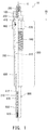
- FIG. 1 shows a glow plug 10.
- the glow plug 10 includes a sheath heater (heat generation device) 800 for generating heat and functions as a heat source for assisting ignition at startup of an internal combustion engine (not shown) such as a diesel engine.
- the glow plug 10 includes the sheath heater 800, an axial rod 200, and a metallic shell 500. These component members of the glow plug 10 are assembled together along the axial direction OD of the glow plug 10.
- FIG. 1 shows an external structure on the right side of an axial line O and a sectional structure on the left side of the axial line O.
- a side toward the sheath heater 800 in the glow plug 10 is called the "forward side”
- a side toward an engagement member 100 is called the "rear side.”
- the metallic shell 500 is a tubular member formed of carbon steel.
- the metallic shell 500 holds the sheath heater 800 at a forward end portion thereof.
- the metallic shell 500 holds the axial rod 200 at a rear end portion thereof through an insulation member 410 and an O-ring 460.
- the position of the insulation member 410 along the axial line O is fixed as a result of a ring 300 in contact with the rear end of the insulation member 410 being crimped to the axial rod 200.
- a portion of the axial rod 200 extending from the insulation member 410 to the sheath heater 800 is disposed in an axial hole 510 of the metallic shell 500.
- the axial hole 510 is a through hole formed along the axial line O and is greater in diameter than the axial rod 200.
- the metallic shell 500 further includes a tool engagement portion 520 and an external thread portion 540.
- a tool (not shown) is engaged with the tool engagement portion 520 of the metallic shell 500 for attaching and detaching the glow plug 10.
- the external thread portion 540 meshes with an internal thread formed in an internal combustion engine (not shown).
- the axial rod 200 is a circular columnar (rodlike) member formed of an electrically conductive material. While being inserted through the axial hole 510 of the metallic shell 500, the axial rod 200 is disposed in position along the axial line O.
- the axial rod 200 includes a forward end portion 210 formed at the forward end side and an external thread portion 290 provided at the rear end side. The forward end portion 210 is inserted into the sheath heater 800. The external thread portion 290 protrudes rearward from the metallic shell 500. The engagement member 100 meshes with the external thread portion 290.
- FIG. 2 is a sectional view showing the structure of a sheath heater 800 in detail.
- the sheath heater 800 includes a sheath tube 810, a heat generation coil 820, a rear coil 830, and an insulator 870.
- the heat generation coil 820 is also called the "forward end coil.”
- the heat generation coil 820 corresponds to the coiled heat generation element of the present invention.
- the sheath tube 810 is a tubular member extending in the axial direction OD and having a closed forward end and corresponds to the tubular member of the present invention.
- the sheath tube 810 accommodates therein the heat generation coil 820, the rear coil 830, and the insulator 870.
- the sheath tube 810 includes a side portion 814 extending in the axial direction OD, a forward end portion 813 connected to the forward end of the side portion 814 and curved outward, and a rear end portion 819 opening in a direction opposite the forward end portion 813.
- the forward end portion 210 of the axial rod 200 is inserted into the sheath tube 810 from the rear end portion 819.
- the sheath tube 810 is electrically insulated from the axial rod 200 by a packing 600 and the insulator 870. Meanwhile, the sheath tube 810 is in contact with the metallic shell 500 to thereby be electrically connected to the metallic shell 500.
- the sheath tube 810 is formed of, for example, austenitic stainless steel which contains iron (Fe), chromium (Cr), and carbon (C), or a nickel (Ni)-based alloy such as INCONEL 601 (INCONEL is a registered trademark) or Alloy602 (corresponding to DIN2.4633 alloy specified by German Industrial Standard (DIN)).
- the insulator 870 is formed of powder of an electrical insulation material.
- magnesium oxide (MgO) powder is used as the insulator 870.
- the insulator 870 is filled into (disposed in) a gap which remains in the sheath tube 810 as a result of disposition of the axial rod 200, the heat generation coil 820, and the rear coil 830 in the sheath tube 810, thereby providing electrical insulation in the gap.
- the heat generation coil 820 is disposed in the sheath tube 810 along the axial direction OD and generates heat by energization thereof.
- the heat generation coil 820 includes a forward end portion 822, which is a forward coil end portion, and a rear end portion 829, which is a rear coil end portion.
- the forward end portion 822 is located in the forward end portion 813 of the sheath tube 810 and electrically connected to the sheath tube 810.
- the rear end portion 829 is electrically connected to the rear coil 830 through a connection 840 formed as a result of welding of the heat generation coil 820 and the rear coil 830.
- the main component of the heat generation coil 820 is tungsten (W).
- the main component is a substance whose content (% by mass) is 50% by mass or higher.
- the tungsten (W) content of the heat generation coil 820 is 99% by mass or higher.
- the wire diameter of the heat generation coil 820 is preferably 0.1 mm to 0.25 mm.
- the rear coil 830 includes a forward end portion 831, which is a forward coil end portion, and a rear end portion 839, which is a rear coil end portion.
- the forward end portion 831 is welded to the rear end portion 829 of the heat generation coil 820 to thereby be electrically connected to the heat generation coil 820.
- the rear end portion 839 is joined to the forward end portion 210 of the axial rod 200 to thereby be electrically connected to the axial rod 200.
- the rear coil 830 is formed of, for example, a nickel (Ni)-chromium (Cr) alloy or an iron (Fe)-chromium (Cr)-aluminum (Al) alloy.
- the resistance R 20 of the glow plug 10 at 20°C is 0.6 ⁇ or less.
- the resistance R 20 of the glow plug 10 at 20°C is the sum of the resistance of the heat generation coil 820 at 20°C and the resistance of the rear coil 830 at 20°C.
- the resistance R 20 of the glow plug 10 at 20°C is 0.4 ⁇ .
- a resistance ratio R1 which is the ratio of the resistance R1 1000 of the heat generation coil 820 at 1,000°C to the resistance R1 20 of the heat generation coil 820 at 20°C and a resistance ratio R2 which is the ratio of the resistance R2 1000 of the rear coil 830 at 1,000°C to the resistance R2 20 of the rear coil 830 at 20°C satisfy a relation of R1 > R2.
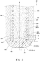
- FIG. 3 is a sectional view showing the forward end portion 813 of the sheath tube 810 and its periphery. The forward end of the sheath tube 810 is closed with the fusion zone 891.
- FIG. 3 shows a cross section of the glow plug 10 taken along the axial line O of the glow plug 10 such that the same number of cross sections of the heat generation coil 820 appear in the fusion zone 891 on opposite sides of the axial line O.
- the right side of the axial line O is taken as one side of the axial line O, and the left side is taken as the other side.
- two cross sections of the heat generation coil 820 appear in the fusion zone 891 on each of opposite sides of the axial line O.
- FIG. 3 shows the heat generation coil 820, the sheath tube 810, and the insulator 870, which are cut along a plane passing through the axial line O.
- the fusion zone 891 of the sheath tube 810 contains columnar crystals (dendrite), whereas a base metal portion 893 other than the fusion zone 891 has a microstructure different from that of the fusion zone 891.
- Examples of the microstructure of the base metal portion 893 include a fibrous microstructure and a forged microstructure.
- the microstructure can be identified as columnar crystals, a fibrous microstructure, or a forged microstructure by a publicly known metal microstructure observation method; specifically, by electrolytic etching of a cut surface in an oxalate solution (JIS G 5071 2012), for example.
- n turns (n is a natural number) of the heat generation coil 820 are inserted into the fusion zone 891.
- two turns of the heat generation coil 820 at the forward end are inserted into the fusion zone 891.
- the first turn 901 and the second turn 902 appear in this order from the forward end side (lower side in the drawing) on opposite sides of the axial line O.
- the third turn 903 and the fourth turn 904 appear in this order from the forward end side (lower side in the drawing) on the opposite sides of the axial line O.
- the rearmost one of the cross sections of the heat generation coil 820 appearing in the fusion zone 891 on one side of the axial line O will be referred to as a first heat-generation-element cross section 902a.
- a cross section which is one of the cross sections of the heat generation coil 820 appearing in the fusion zone 891 on the one side of the axial line O and which is located immediately forward of the first heat-generation-element cross section 902a will be referred to as a fourth heat-generation-element cross section 901 a.
- the forwardmost one of the cross sections of the heat generation coil 820 appearing externally of the fusion zone 891 on the one side of the axial line O will be referred to as a second heat-generation-element cross section 903a.
- a cross section which is one of the cross sections of the heat generation element 820 appearing externally of the fusion zone 891 on the one side of the axial line O and which is located immediately rearward of the second heat-generation-element cross section 903a will be referred to as a third heat-generation-element cross section 904a.
- a distance A between the first heat-generation-element cross section 902a and the second heat-generation-element cross section 903a is rendered greater than a distance B between the second heat-generation-element cross section 903a and the third heat-generation-element cross section 904a.
- the distance A is preferably greater than 0.2 mm and not greater than 0.6 mm.
- the distance B is preferably not less than 0.1 mm and not greater than 0.2 mm.
- the distance A i.e., space
- the distance A i.e., space
- the distance A is increased such that the rear end surface 895 of the fusion zone 891 is disposed in the space. Accordingly, even when the amount of the melted material of the sheath tube 810 varies and thus the position of the rear end surface 895 of the fusion zone 891 varies in the axial direction, the rear end surface 895 can be positioned between the first heat-generation-element cross section 902a and the second heat-generation-element cross section 903a without fail.
- the distance A and the distance B satisfy the following relational expression. 1.30 ⁇ A / B ⁇ 4.00
- A/B is equal to or greater than 1.30, the variation in thermal performance among individual glow plugs can be suppressed.
- A/B is equal to or less than 4.00, the glow plug 10 can have sufficiently high heat-up performance.
- a distance C between the fourth heat-generation-element cross section 901 a and the first heat-generation-element cross section 902a is equal to or less than the distance B.
- the distance C between the fourth heat-generation-element cross section 901a and the first heat-generation-element cross section 902a is preferably not less than 0 mm and not greater than 0.10 mm.
- the distance C By setting the distance C to be equal to or less than the distance B, the wall thickness of the sheath tube 810 between the forward end of the heat generation coil 820 and the surface of the sheath tube 810 (thickness indicated by symbol D in FIG. 3 ) can be rendered sufficiently large. As a result, it is possible to prevent exposure of the coil 820 which would otherwise occur when the sheath tube 810 wears, whereby durability can be improved.
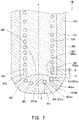
- a glow plug 10 of another (second) embodiment (modification) will be described with reference to FIG. 7 .
- constituent members or portions of the glow plug 10 of the second embodiment which are approximately the same as those of the glow plug 10 of the above-described embodiment are denoted by like reference numerals, and description of their structures, actions, and effects is omitted.
- the radially outermost end 901 aa of the fourth heat-generation-element cross section 901 a is located inward of the radially innermost end 902aa of the first heat-generation-element cross section 902a.
- the glow plug 10 of the second embodiment differs from the glow plug 10 of the above-described embodiment in the following point.
- the rearmost end 901 ab of the fourth heat-generation-element cross section 901 a is located rearward of the forwardmost end 902ab of the first heat-generation-element cross section 902a.
- the fourth heat-generation-element cross section 901 a and the first heat-generation-element cross section 902a are disposed to overlap each other in the axial direction OD.
- FIG. 4 is a flowchart showing a method of manufacturing the glow plug 10.
- the heat generation coil 820 and the axial rod 200 are welded together (step S10).
- the heat generation coil 820 and the rear coil 830 are welded together; further, the rear end portion 839 of the rear coil 830 and the forward end portion 210 of the axial rod 200 are welded together.
- the forward end portion 822 of the heat generation coil 820 and the forward end portion 813 of the sheath tube 810 are welded together (step S20).
- Step S20 is also called the "welding process.”
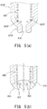
- FIGS. 5(a) and 5(b) are explanatory views showing a welding process in step S20.
- a sheath tube 810P which includes a forward end portion 813P having an opening 815 and which is shaped such that diameter gradually reduces toward the opening 815.
- the forward end portion 822 of the heat generation coil 820 is disposed inside the forward end portion 813P of the prepared sheath tube 810P such that the second turn 822P of the heat generation coil 820 comes into contact with the sheath tube 810P ( FIG. 5(a) ).
- the forward end portion 813P is melted by, for example, arc welding from outside and then is solidified to close the opening 815
- the forward end portion 822 of the heat generation coil 820 and the forward end portion 813 of the sheath tube 810 are welded together ( FIG. 5(b) ).
- the forward end portion 822 of the heat generation coil 820 is surrounded by and embedded in the forward end portion 813 of the sheath tube 810.
- output of the welding machine, welding time, etc. are adjusted such that the heat generation coil 820 and the sheath tube 810 are welded together at a temperature lower than the melting point of the heat generation coil 820 and higher than the melting point of the sheath tube 810.
- the thickness of an alloy portion formed of the alloy is 10 ( ⁇ m) or less.
- the thickness of the alloy portion can be calculated by detecting the alloy portion through analysis of a region in the vicinity of the boundary between the forward end portion 822 of the heat generation coil 820 and the forward end portion 813 of the sheath tube 810 by use of, for example, EPMA (Electron Probe Micro Analyzer).
- EPMA Electro Probe Micro Analyzer
- the insulator 870 is filled into the sheath tube 810 (step S30).
- the insulator 870 covers the heat generation coil 820, the rear coil 830, and the axial rod 200 to thereby fill a gap formed in the sheath tube 810, whereby assembly of the sheath heater 800 is completed.
- swaging is performed on the sheath heater 800 (step S40). Swaging is performed such that striking force is applied to the sheath heater 800 to thereby reduce the diameter of the sheath heater 800, so as to densify the insulator 870 filled into the sheath tube 810.
- striking force is applied to the sheath heater 800 as a result of swaging, the striking force is transmitted to the interior of the sheath heater 800, thereby densifying the insulator 870.
- step S50 After swaging is performed on the sheath heater 800, the sheath heater 800 and the metallic shell 500 are combined to thereby assemble the glow plug 10 (step S50), whereby the glow plug 10 is completed.
- the sheath heater 800 integrated with the axial rod 200 is fixedly press-fitted into the axial hole 510 of the metallic shell 500; the O-ring 460 and the insulation member 410 are fitted to the axial rod 200 at a rear end portion of the metallic shell 500; and the engagement member 100 is meshed with the external thread portion 290 of the axial rod 200 located rearward of the rear end of the metallic shell 500.
- step S50 aging is performed on the glow plug 10. Specifically, the assembled glow plug 10 is energized so that the sheath heater 800 generates heat, thereby forming an oxide film on the outer surface of the sheath heater 800.
- experimental examples 2 to 6 are examples of the present invention, and experimental example 1 is a comparative example.
- the forward end shape of the heat generation coil 820 was adjusted so as to adjust the distance A, the distance B, and the distance C.
- Other conditions are as follows:
- the sheath heater 800 was cut such that the region where the forward end portion 831 of the rear coil 830 and the rear end portion 829 of the heat generation coil 820 are welled together appeared on the cut surface on the left side (on the other side), and the clearances between the cross sections of the heat generation coil 820 were measured on the cut surface on the right side (on one side).
- the rated voltage was determined as follows. Namely, the voltage sensitivity of the first glow plug for each experimental example was measured, the relation between voltage and temperature was determined, and a voltage at which the temperature becomes 1,100°C was used as the rated voltage.
- the temperature was measured at a position located 2 mm from the forward end of the sheath tube 810 by use of a PR thermocouple (platinum-platinum rhodium thermocouple) and a radiation thermometer.
- PR thermocouple platinum-platinum rhodium thermocouple
- radiation thermometer a radiation thermometer
- a voltage for increasing the glow plug temperature by 1,000°C in two seconds was applied to each glow plug 10; then, a voltage for saturating the glow plug temperature at 1,100°C was applied to each glow plug 10 continuously for 180 seconds. Subsequently, each glow plug 10 was cooled by wind for 120 seconds for lowering the glow plug temperature to room temperature. With this procedure taken as one cycle, a cycle test was conducted. Each glow plug 10 was subjected to 7,000 test cycles. Each glow plug 10 was evaluated on the basis of the results of the determination as to whether or not a wire breakage occurred during the durability test.
- the temperature was measured at a position located 2 mm from the forward end of the sheath tube 810 by use of a PR thermocouple (platinum-platinum rhodium thermocouple) and a radiation thermometer.
- PR thermocouple platinum-platinum rhodium thermocouple
- radiation thermometer a radiation thermometer
- a voltage of 11 V was applied to each glow plug 10 for 2 seconds, and its temperature after elapse of 2 seconds was measured.
- the temperature was measured at a position located 2 mm from the forward end of the sheath tube 810 by use of a PR thermocouple (platinum-platinum rhodium thermocouple) and a radiation thermometer.
- PR thermocouple platinum-platinum rhodium thermocouple
- the rapid heat-up performance was evaluated as follows.
- Table 1 shows the test results.
- Table 1 Experimental example A (mm) B (mm) C (mm) A/B C/B Temp. variation Durability Rapid heat-up performance 1 0.10 0.10 0.07 1.00 0.700 X X (1) ⁇ 2 0.13 0.10 0.07 1.30 0.700 ⁇ ⁇ ⁇ 3 0.40 0.10 0.07 4.00 0.700 ⁇ ⁇ ⁇ 4 0.45 0.10 0.07 4.50 0.700 ⁇ ⁇ X 5 0.50 0.10 0.10 5.00 1.000 ⁇ ⁇ ⁇ 6 0.50 0.10 0.13 5.00 1.300 ⁇ X (2) ⁇ (1) The heat generation coil came off the sheath tube. (2) The forward end of the heat generation coil was exposed from the forward end of the sheath tube.
Landscapes
- Engineering & Computer Science (AREA)
- Chemical & Material Sciences (AREA)
- Combustion & Propulsion (AREA)
- Mechanical Engineering (AREA)
- General Engineering & Computer Science (AREA)
- Resistance Heating (AREA)
Abstract
Description
- The present invention relates to a glow plug.
- In recent years, in order to cope with stricter exhaust gas regulations on diesel engines, glow plugs have been required to provide higher heating-up temperature. In order to provide higher heating-up temperature, a glow plug in which a heat generation element containing tungsten (W) as a main component is disposed in a tubular member (tube) is proposed (see
WO2014/206847 ). - In the case of the glow plug of
WO2014/206847 , thermal performance may vary among individual glow plugs. Such variation occurs because tungsten (W) used as a main component of a heat generation element is large in resistance ratio (the ratio of the resistance of the heat generation element at 1,000°C to the resistance of the heat generation element at 20°C). If the resistance of the heat generation element at room temperature varies among individual glow plugs, the resistance of the heat generation element when energized varies more greatly among individual glow plugs, and consequently, thermal performance may vary among individual glow plugs. - Incidentally, in the case of the glow plug of
WO2014/206847 , the heat generation element is inserted into a fusion zone at the forward end of a tubular member and is joined to the tubular member through the fusion zone. At that time, if the amount of the material of the heat generation element inserted into the fusion zone varies among individual glow plugs, the resistance of the heat generation element at room temperature may vary among individual glow plugs. In particular, in manufacture of the glow plug, the forward end of the tubular member is melted and then solidified to thereby fix the heat generation element in the fusion zone. At that time, if the amount of the melted material of the tubular member varies, the amount of insertion of the heat generation element into the fusion zone may vary among individual glow plugs. - The present invention has been conceived to solve the above problem and an object of the present invention is to reduce variation in thermal performance among individual glow plugs.
- (1) A mode of the present invention provides a glow plug comprising: a tubular member whose forward end is closed with a fusion zone, and a coiled heat generation element disposed in the tubular member and containing W as a main component. A forward end portion of the heat generation element is inserted into the fusion zone to thereby be joined to the tubular member. In a cross section of the glow plug taken along an axial line of the glow plug, with a cross section which is a rearmost one of cross sections of the heat generation element appearing in the fusion zone on one side of the axial line and which is disposed at least partially within the fusion zone being defined as a first heat-generation-element cross section, with a forwardmost one of cross sections of the heat generation element appearing externally of the fusion zone on the one side of the axial line being defined as a second heat-generation-element cross section, and with a cross section which is one of the cross sections of the heat generation element appearing externally of the fusion zone on the one side of the axial line and which is located immediately rearward of the second heat-generation-element cross section being defined as a third heat-generation-element cross section, a distance A in the direction of the axial line between a rearmost end of the first heat-generation-element cross section and a forwardmost end of the second heat-generation-element cross section is greater than a distance B in the direction of the axial line between a rearmost end of the second heat-generation-element cross section and a forwardmost end of the third heat-generation-element cross section.
According to the mode of the present invention, the distance A is rendered greater than the distance B. Namely, the distance A (i.e., space) between the first heat-generation-element cross section and the second heat-generation-element cross section is increased such that the rear end surface of the fusion zone is disposed in the space. Accordingly, even when, for example, the amount of the melted material of the tubular member varies and thus the position of the rear end surface of the fusion zone varies some extent in the axial direction, the rear end surface of the fusion zone can be positioned in the inter-turn space between the first heat-generation-element cross section and the second heat-generation-element cross section without fail. Thus, only a predetermined amount of the material of the heat generation element at the forward end thereof can be reliably inserted into the fusion zone, whereby variation in the resistance of the heat generation element at room temperature among individual glow plugs can be suppressed. Accordingly, variation in thermal performance among individual glow plugs can be reduced.
Notably, the "first heat-generation-element cross section" may be disposed at least partially within the fusion zone. Specifically, the entire first heat-generation-element cross section may be disposed within the fusion zone; alternatively, a portion of the first heat-generation-element cross section may be disposed within the fusion zone. - (2) The glow plug according to section (1) may be configured such that the distance A and the distance B satisfy a relational expression of 1.30 ≤ A/B ≤ 4.00.
When the above-described relational expression is satisfied, variation in the resistance of the heat generation element at room temperature among individual glow plugs can be suppressed while the heat-up performance of the glow plug is secured to a sufficient degree. - (3) The glow plug according to section (1) or (2) may be configured such that, in the cross section of the glow plug, with a cross section which is one of the cross sections of the heat generation element appearing in the fusion zone on the one side of the axial line and which is located immediately forward of the first heat-generation-element cross section being defined as a fourth heat-generation-element cross section, a distance C in the direction of the axial line between a rearmost end of the fourth heat-generation-element cross section and a forwardmost end of the first heat-generation-element cross section (including the case where C = 0) is equal to or less than the distance B.
In this case, since the distance C between the fourth heat-generation-element cross section and the first heat-generation-element cross section is rendered equal to or less than the distance B, the wall thickness of the tubular member between the forward end of the heat generation element and the surface of the tubular member can be rendered sufficiently large. As a result, it is possible to prevent exposure of the heat generation element, which would otherwise occur when the tubular member wears.
In this case, the glow plug can simultaneously achieve reduction of thermal performance variation and improvement of durability.
Notably, the expression "C = 0" means that the axial position of the rearmost end of the fourth heat-generation-element cross section is the same as that of the forwardmost end of the first heat-generation-element cross section. - (4) The glow plug according to section (1) or (2) may be configured such that, in the cross section of the glow plug, with a cross section which is one of the cross sections of the heat generation element appearing in the fusion zone on the one side of the axial line and which is located immediately forward of the first heat-generation-element cross section being defined as a fourth heat-generation-element cross section, a radially outermost end of the fourth heat-generation-element cross section is located inward of a radially innermost end of the first heat-generation-element cross section, and a rearmost end of the fourth heat-generation-element cross section is located rearward of a forwardmost end of the first heat-generation-element cross section.
- In this case, since the rearmost end of the fourth heat-generation-element cross section is located rearward of the forwardmost end of the first heat-generation-element cross section, the wall thickness of the tubular member between the forward end of the heat generation element and the surface of the tubular member can be rendered sufficiently large. As a result, it is possible to prevent exposure of the heat generation element, which would otherwise occur when the tubular member wears.
- In this case, the glow plug can simultaneously achieve reduction of thermal performance variation and improvement of durability.
- The invention will be further described by way of non-limitative example with reference to the accompanying drawings, in which:
-
FIG. 1 is a view showing a glow plug. -
FIG. 2 is a sectional view showing the structure of a sheath heater in detail. -
FIG. 3 is a sectional view showing a forward end portion of a sheath tube and its periphery. -
FIG. 4 is a flowchart showing a method of manufacturing the glow plug. -
FIGS. 5(a) and 5(b) are explanatory views showing a welding process in step S20. -
FIGS. 6(a) and 6(b) are explanatory views showing a welding process in step S20 of another embodiment. -
FIG. 7 is a sectional view showing a forward end portion of a sheath tube of still another embodiment and its periphery. -
FIG. 1 shows aglow plug 10. Theglow plug 10 includes a sheath heater (heat generation device) 800 for generating heat and functions as a heat source for assisting ignition at startup of an internal combustion engine (not shown) such as a diesel engine. Theglow plug 10 includes thesheath heater 800, anaxial rod 200, and ametallic shell 500. These component members of theglow plug 10 are assembled together along the axial direction OD of theglow plug 10.FIG. 1 shows an external structure on the right side of an axial line O and a sectional structure on the left side of the axial line O. In the present specification, a side toward thesheath heater 800 in theglow plug 10 is called the "forward side," and a side toward anengagement member 100 is called the "rear side." - The
metallic shell 500 is a tubular member formed of carbon steel. Themetallic shell 500 holds thesheath heater 800 at a forward end portion thereof. Also, themetallic shell 500 holds theaxial rod 200 at a rear end portion thereof through aninsulation member 410 and an O-ring 460. The position of theinsulation member 410 along the axial line O is fixed as a result of aring 300 in contact with the rear end of theinsulation member 410 being crimped to theaxial rod 200. Further, a portion of theaxial rod 200 extending from theinsulation member 410 to thesheath heater 800 is disposed in anaxial hole 510 of themetallic shell 500. Theaxial hole 510 is a through hole formed along the axial line O and is greater in diameter than theaxial rod 200. In a state in which theaxial rod 200 is positioned in theaxial hole 510, a gap is formed between theaxial rod 200 and the wall of theaxial hole 510 for electrically insulating them from each other. Thesheath heater 800 is press-fitted into a forward end portion of theaxial hole 510 to thereby be joined to the forward end portion. Themetallic shell 500 further includes atool engagement portion 520 and anexternal thread portion 540. A tool (not shown) is engaged with thetool engagement portion 520 of themetallic shell 500 for attaching and detaching theglow plug 10. Theexternal thread portion 540 meshes with an internal thread formed in an internal combustion engine (not shown). - The
axial rod 200 is a circular columnar (rodlike) member formed of an electrically conductive material. While being inserted through theaxial hole 510 of themetallic shell 500, theaxial rod 200 is disposed in position along the axial line O. Theaxial rod 200 includes aforward end portion 210 formed at the forward end side and anexternal thread portion 290 provided at the rear end side. Theforward end portion 210 is inserted into thesheath heater 800. Theexternal thread portion 290 protrudes rearward from themetallic shell 500. Theengagement member 100 meshes with theexternal thread portion 290. -
FIG. 2 is a sectional view showing the structure of asheath heater 800 in detail. With theforward end portion 210 of theaxial rod 200 inserted into thesheath heater 800, thesheath heater 800 is press-fitted into theaxial hole 510 of themetallic shell 500 to thereby be joined to themetallic shell 500. Thesheath heater 800 includes asheath tube 810, aheat generation coil 820, arear coil 830, and aninsulator 870. Theheat generation coil 820 is also called the "forward end coil." Theheat generation coil 820 corresponds to the coiled heat generation element of the present invention. - The
sheath tube 810 is a tubular member extending in the axial direction OD and having a closed forward end and corresponds to the tubular member of the present invention. Thesheath tube 810 accommodates therein theheat generation coil 820, therear coil 830, and theinsulator 870. Thesheath tube 810 includes aside portion 814 extending in the axial direction OD, aforward end portion 813 connected to the forward end of theside portion 814 and curved outward, and arear end portion 819 opening in a direction opposite theforward end portion 813. Theforward end portion 210 of theaxial rod 200 is inserted into thesheath tube 810 from therear end portion 819. Thesheath tube 810 is electrically insulated from theaxial rod 200 by a packing 600 and theinsulator 870. Meanwhile, thesheath tube 810 is in contact with themetallic shell 500 to thereby be electrically connected to themetallic shell 500. Thesheath tube 810 is formed of, for example, austenitic stainless steel which contains iron (Fe), chromium (Cr), and carbon (C), or a nickel (Ni)-based alloy such as INCONEL 601 (INCONEL is a registered trademark) or Alloy602 (corresponding to DIN2.4633 alloy specified by German Industrial Standard (DIN)). - The
insulator 870 is formed of powder of an electrical insulation material. For example, magnesium oxide (MgO) powder is used as theinsulator 870. Theinsulator 870 is filled into (disposed in) a gap which remains in thesheath tube 810 as a result of disposition of theaxial rod 200, theheat generation coil 820, and therear coil 830 in thesheath tube 810, thereby providing electrical insulation in the gap. - The
heat generation coil 820 is disposed in thesheath tube 810 along the axial direction OD and generates heat by energization thereof. Theheat generation coil 820 includes aforward end portion 822, which is a forward coil end portion, and arear end portion 829, which is a rear coil end portion. Theforward end portion 822 is located in theforward end portion 813 of thesheath tube 810 and electrically connected to thesheath tube 810. Therear end portion 829 is electrically connected to therear coil 830 through aconnection 840 formed as a result of welding of theheat generation coil 820 and therear coil 830. The main component of theheat generation coil 820 is tungsten (W). Notably, the main component is a substance whose content (% by mass) is 50% by mass or higher. Preferably, the tungsten (W) content of theheat generation coil 820 is 99% by mass or higher. - No particular limitation is imposed on the wire diameter of the
heat generation coil 820; however, the wire diameter is preferably 0.1 mm to 0.25 mm. - The
rear coil 830 includes aforward end portion 831, which is a forward coil end portion, and arear end portion 839, which is a rear coil end portion. Theforward end portion 831 is welded to therear end portion 829 of theheat generation coil 820 to thereby be electrically connected to theheat generation coil 820. Therear end portion 839 is joined to theforward end portion 210 of theaxial rod 200 to thereby be electrically connected to theaxial rod 200. Therear coil 830 is formed of, for example, a nickel (Ni)-chromium (Cr) alloy or an iron (Fe)-chromium (Cr)-aluminum (Al) alloy. - In view of securement of rapid heat-up performance, preferably, the resistance R20 of the
glow plug 10 at 20°C is 0.6 Ω or less. In the present embodiment, the resistance R20 of theglow plug 10 at 20°C is the sum of the resistance of theheat generation coil 820 at 20°C and the resistance of therear coil 830 at 20°C. In the present embodiment, the resistance R20 of theglow plug 10 at 20°C is 0.4 Ω. In the present embodiment, a resistance ratio R1 which is the ratio of the resistance R11000 of theheat generation coil 820 at 1,000°C to the resistance R120 of theheat generation coil 820 at 20°C and a resistance ratio R2 which is the ratio of the resistance R21000 of therear coil 830 at 1,000°C to the resistance R220 of therear coil 830 at 20°C satisfy a relation of R1 > R2. -
FIG. 3 is a sectional view showing theforward end portion 813 of thesheath tube 810 and its periphery. The forward end of thesheath tube 810 is closed with thefusion zone 891. -
FIG. 3 shows a cross section of theglow plug 10 taken along the axial line O of theglow plug 10 such that the same number of cross sections of theheat generation coil 820 appear in thefusion zone 891 on opposite sides of the axial line O. InFIG. 3 , the right side of the axial line O is taken as one side of the axial line O, and the left side is taken as the other side. InFIG. 3 , two cross sections of theheat generation coil 820 appear in thefusion zone 891 on each of opposite sides of the axial line O.FIG. 3 shows theheat generation coil 820, thesheath tube 810, and theinsulator 870, which are cut along a plane passing through the axial line O. - The
fusion zone 891 of thesheath tube 810 contains columnar crystals (dendrite), whereas abase metal portion 893 other than thefusion zone 891 has a microstructure different from that of thefusion zone 891. Examples of the microstructure of thebase metal portion 893 include a fibrous microstructure and a forged microstructure. The microstructure can be identified as columnar crystals, a fibrous microstructure, or a forged microstructure by a publicly known metal microstructure observation method; specifically, by electrolytic etching of a cut surface in an oxalate solution (JIS G 5071 2012), for example. - Forward n turns (n is a natural number) of the
heat generation coil 820 are inserted into thefusion zone 891. In the present embodiment, two turns of theheat generation coil 820 at the forward end are inserted into thefusion zone 891. - As shown in
FIG. 3 , in thefusion zone 891, thefirst turn 901 and thesecond turn 902 appear in this order from the forward end side (lower side in the drawing) on opposite sides of the axial line O. - In a region outside the
fusion zone 891, thethird turn 903 and thefourth turn 904 appear in this order from the forward end side (lower side in the drawing) on the opposite sides of the axial line O. - The rearmost one of the cross sections of the
heat generation coil 820 appearing in thefusion zone 891 on one side of the axial line O will be referred to as a first heat-generation-element cross section 902a. Also, a cross section which is one of the cross sections of theheat generation coil 820 appearing in thefusion zone 891 on the one side of the axial line O and which is located immediately forward of the first heat-generation-element cross section 902a will be referred to as a fourth heat-generation-element cross section 901 a. Also, the forwardmost one of the cross sections of theheat generation coil 820 appearing externally of thefusion zone 891 on the one side of the axial line O will be referred to as a second heat-generation-element cross section 903a. Further, a cross section which is one of the cross sections of theheat generation element 820 appearing externally of thefusion zone 891 on the one side of the axial line O and which is located immediately rearward of the second heat-generation-element cross section 903a will be referred to as a third heat-generation-element cross section 904a. - In the present embodiment, a distance A between the first heat-generation-
element cross section 902a and the second heat-generation-element cross section 903a is rendered greater than a distance B between the second heat-generation-element cross section 903a and the third heat-generation-element cross section 904a. - No particular limitation is imposed on the distance A; however, the distance A is preferably greater than 0.2 mm and not greater than 0.6 mm.
- No particular limitation is imposed on the distance B; however, the distance B is preferably not less than 0.1 mm and not greater than 0.2 mm.
- The following actions and effects are yielded when the distance A is rendered greater than the distance B.
- According to one mode of the present invention, the distance A (i.e., space) between the first heat-generation-
element cross section 902a and the second heat-generation-element cross section 903a is increased such that therear end surface 895 of thefusion zone 891 is disposed in the space. Accordingly, even when the amount of the melted material of thesheath tube 810 varies and thus the position of therear end surface 895 of thefusion zone 891 varies in the axial direction, therear end surface 895 can be positioned between the first heat-generation-element cross section 902a and the second heat-generation-element cross section 903a without fail. Thus, only a predetermined amount of the material of theheat generation coil 820 at the forward end thereof can be reliably inserted into thefusion zone 891, whereby variation in the resistance at room temperature among individual glow plugs can be suppressed. Accordingly, variation in thermal performance among individual glow plugs can be reduced, and theheat generation coil 820 can be prevented from coming off thesheath tube 810. Notably, the reason why the above-described relation of the distances A and B reduces the variation in thermal performance among individual glow plugs will be described in detail in the after-mentioned section "Examples." - Further, in the present embodiment, preferably, the distance A and the distance B satisfy the following relational expression.

- When A/B is equal to or greater than 1.30, the variation in thermal performance among individual glow plugs can be suppressed. When A/B is equal to or less than 4.00, the
glow plug 10 can have sufficiently high heat-up performance. - Further, in the present embodiment, desirably, a distance C between the fourth heat-generation-
element cross section 901 a and the first heat-generation-element cross section 902a is equal to or less than the distance B. - No particular limitation is imposed on the distance C between the fourth heat-generation-
element cross section 901a and the first heat-generation-element cross section 902a; however, the distance C is preferably not less than 0 mm and not greater than 0.10 mm. - By setting the distance C to be equal to or less than the distance B, the wall thickness of the
sheath tube 810 between the forward end of theheat generation coil 820 and the surface of the sheath tube 810 (thickness indicated by symbol D inFIG. 3 ) can be rendered sufficiently large. As a result, it is possible to prevent exposure of thecoil 820 which would otherwise occur when thesheath tube 810 wears, whereby durability can be improved. - A
glow plug 10 of another (second) embodiment (modification) will be described with reference toFIG. 7 . Notably, constituent members or portions of theglow plug 10 of the second embodiment which are approximately the same as those of theglow plug 10 of the above-described embodiment are denoted by like reference numerals, and description of their structures, actions, and effects is omitted. - In the
glow plug 10 of the second embodiment, as in theglow plug 10 of the above-described embodiment, the radiallyoutermost end 901 aa of the fourth heat-generation-element cross section 901 a is located inward of the radially innermost end 902aa of the first heat-generation-element cross section 902a. - The
glow plug 10 of the second embodiment differs from theglow plug 10 of the above-described embodiment in the following point. - Namely, the
rearmost end 901 ab of the fourth heat-generation-element cross section 901 a is located rearward of the forwardmost end 902ab of the first heat-generation-element cross section 902a. Namely, the fourth heat-generation-element cross section 901 a and the first heat-generation-element cross section 902a are disposed to overlap each other in the axial direction OD. By virtue of this arrangement, the wall thickness of thesheath tube 810 between the forward end of theheat generation coil 820 and the surface of the sheath tube 810 (thickness indicated by symbol D inFIG. 7 ) can be rendered sufficiently large. As a result, it is possible to prevent exposure of thecoil 820 which would otherwise occur when thesheath tube 810 wears, whereby durability can be improved. -
FIG. 4 is a flowchart showing a method of manufacturing theglow plug 10. In manufacture of theglow plug 10, first, theheat generation coil 820 and theaxial rod 200 are welded together (step S10). Specifically, theheat generation coil 820 and therear coil 830 are welded together; further, therear end portion 839 of therear coil 830 and theforward end portion 210 of theaxial rod 200 are welded together. Next, theforward end portion 822 of theheat generation coil 820 and theforward end portion 813 of thesheath tube 810 are welded together (step S20). Step S20 is also called the "welding process." -
FIGS. 5(a) and 5(b) are explanatory views showing a welding process in step S20. In the welding process, first, there is prepared asheath tube 810P which includes aforward end portion 813P having anopening 815 and which is shaped such that diameter gradually reduces toward theopening 815. Theforward end portion 822 of theheat generation coil 820 is disposed inside theforward end portion 813P of theprepared sheath tube 810P such that thesecond turn 822P of theheat generation coil 820 comes into contact with thesheath tube 810P (FIG. 5(a) ). Next, while theforward end portion 813P is melted by, for example, arc welding from outside and then is solidified to close theopening 815, theforward end portion 822 of theheat generation coil 820 and theforward end portion 813 of thesheath tube 810 are welded together (FIG. 5(b) ). By this procedure, theforward end portion 822 of theheat generation coil 820 is surrounded by and embedded in theforward end portion 813 of thesheath tube 810. Also, in the welding process, output of the welding machine, welding time, etc. are adjusted such that theheat generation coil 820 and thesheath tube 810 are welded together at a temperature lower than the melting point of theheat generation coil 820 and higher than the melting point of thesheath tube 810. - Notably, in the case where an alloy of a metal used to form the
sheath tube 810 and a metal used to form theheat generation coil 820 is formed between theforward end portion 813 of thesheath tube 810 and theforward end portion 822 of theheat generation coil 820, the thickness of an alloy portion formed of the alloy is 10 (µm) or less. The thickness of the alloy portion can be calculated by detecting the alloy portion through analysis of a region in the vicinity of the boundary between theforward end portion 822 of theheat generation coil 820 and theforward end portion 813 of thesheath tube 810 by use of, for example, EPMA (Electron Probe Micro Analyzer). Notably, in theglow plug 10 of the present embodiment, the alloy portion is not formed. - When the welding process in step S20 is completed, the
insulator 870 is filled into the sheath tube 810 (step S30). Theinsulator 870 covers theheat generation coil 820, therear coil 830, and theaxial rod 200 to thereby fill a gap formed in thesheath tube 810, whereby assembly of thesheath heater 800 is completed. - After the completion of assembling of the
sheath heater 800, swaging is performed on the sheath heater 800 (step S40). Swaging is performed such that striking force is applied to thesheath heater 800 to thereby reduce the diameter of thesheath heater 800, so as to densify theinsulator 870 filled into thesheath tube 810. When striking force is applied to thesheath heater 800 as a result of swaging, the striking force is transmitted to the interior of thesheath heater 800, thereby densifying theinsulator 870. - After swaging is performed on the
sheath heater 800, thesheath heater 800 and themetallic shell 500 are combined to thereby assemble the glow plug 10 (step S50), whereby theglow plug 10 is completed. Specifically, thesheath heater 800 integrated with theaxial rod 200 is fixedly press-fitted into theaxial hole 510 of themetallic shell 500; the O-ring 460 and theinsulation member 410 are fitted to theaxial rod 200 at a rear end portion of themetallic shell 500; and theengagement member 100 is meshed with theexternal thread portion 290 of theaxial rod 200 located rearward of the rear end of themetallic shell 500. Also, in step S50, aging is performed on theglow plug 10. Specifically, the assembledglow plug 10 is energized so that thesheath heater 800 generates heat, thereby forming an oxide film on the outer surface of thesheath heater 800. - The present invention will be described further in detail by way of example.
- Notably, experimental examples 2 to 6 are examples of the present invention, and experimental example 1 is a comparative example.
- In the glow plugs 10 of each experimental example, the forward end shape of the
heat generation coil 820 was adjusted so as to adjust the distance A, the distance B, and the distance C. Other conditions are as follows: - A tungsten material (wire diameter φ: 0.20 mm) was used to form the
heat generation coil 820. - A nickel-chromium alloy material (wire diameter φ:0.38 mm) was used to form the
rear coil 830. - Resistance at room temperature was adjusted to 0.330 Ω.
- The
sheath tube 810 had an outside diameter of 3.25 mm at a small-diameter portion thereof. - Each distance was measured as follows: each
glow plug 10 after temperature measurement was disassembled, and then thesheath heater 800 was cut along the axial line O of the glow plug such that the same number of cross sections of theheat generation element 820 appeared in thefusion zone 891 on the opposite sides of the axial line O, and the cut surface was used for for measurement. - The
sheath heater 800 was cut such that the region where theforward end portion 831 of therear coil 830 and therear end portion 829 of theheat generation coil 820 are welled together appeared on the cut surface on the left side (on the other side), and the clearances between the cross sections of theheat generation coil 820 were measured on the cut surface on the right side (on one side). - 20 glow plugs 10 were prepared for each experimental example. A rated voltage was applied to each
glow plug 10, and the temperature of the glow plugs 10 was measured after elapse of 100 seconds. The value of 3σ was obtained for the temperatures of the 20 glow plugs 10 for each experimental example and was evaluated as follows. - O (good): The value of 3σ was less than 70°C
- X (poor): The value of 3σ was equal to or greater than 70°C
- The rated voltage was determined as follows. Namely, the voltage sensitivity of the first glow plug for each experimental example was measured, the relation between voltage and temperature was determined, and a voltage at which the temperature becomes 1,100°C was used as the rated voltage.
- Notably, the temperature was measured at a position located 2 mm from the forward end of the
sheath tube 810 by use of a PR thermocouple (platinum-platinum rhodium thermocouple) and a radiation thermometer. - A voltage for increasing the glow plug temperature by 1,000°C in two seconds was applied to each
glow plug 10; then, a voltage for saturating the glow plug temperature at 1,100°C was applied to eachglow plug 10 continuously for 180 seconds. Subsequently, eachglow plug 10 was cooled by wind for 120 seconds for lowering the glow plug temperature to room temperature. With this procedure taken as one cycle, a cycle test was conducted. Eachglow plug 10 was subjected to 7,000 test cycles. Eachglow plug 10 was evaluated on the basis of the results of the determination as to whether or not a wire breakage occurred during the durability test. - O (good): No wire breakage occurred even after 500 hours (about 6,000 cycles)
- X (poor): Wire breakage occurred before 500 hours (about 6,000 cycles)
- Notably, the temperature was measured at a position located 2 mm from the forward end of the
sheath tube 810 by use of a PR thermocouple (platinum-platinum rhodium thermocouple) and a radiation thermometer. - A voltage of 11 V was applied to each
glow plug 10 for 2 seconds, and its temperature after elapse of 2 seconds was measured. The temperature was measured at a position located 2 mm from the forward end of thesheath tube 810 by use of a PR thermocouple (platinum-platinum rhodium thermocouple) and a radiation thermometer. The rapid heat-up performance was evaluated as follows. - O (good): The temperature reached after elapse of 2 seconds was 900°C or higher
- X (poor): The temperature reached after elapse of 2 seconds was lower than 900°C
- Table 1 shows the test results.
Table 1 Experimental example A (mm) B (mm) C (mm) A/B C/B Temp. variation Durability Rapid heat-up performance 1 0.10 0.10 0.07 1.00 0.700 X X(1) ○ 2 0.13 0.10 0.07 1.30 0.700 ○ ○ ○ 3 0.40 0.10 0.07 4.00 0.700 ○ ○ ○ 4 0.45 0.10 0.07 4.50 0.700 ○ ○ X 5 0.50 0.10 0.10 5.00 1.000 ○ ○ ○ 6 0.50 0.10 0.13 5.00 1.300 ○ X(2) ○ (1) The heat generation coil came off the sheath tube.
(2) The forward end of the heat generation coil was exposed from the forward end of the sheath tube. - In experimental examples 2 to 6, the value of 3σ (index of temperature variation) was less than 70°C, and the temperature variation among the individual glow plugs 10 was small. Meanwhile, in experimental example 1, the value of 3σ (index of temperature variation) was equal to or greater than 70°C, and the temperature variation was large. Accordingly, it was confirmed that when the distance A is rendered greater than the distance B, the variation in thermal performance among individual glow plugs can be reduced.
- Further, for experimental examples 2 and 3 which also meet the requirement that the value of A/B is not less than 1.30 and not greater than 4.00, it was confirmed that the variation in thermal performance among individual glow plugs can be suppressed, and rapid heat-up performance can be secured to a sufficient degree.
- Also, in the case of experimental examples 2 to 5 which also meet the requirement that the distance C between the first turn and the second turn is equal to or less than the distance B, even after about 6,000 cycles, the forward end of the heat generation coil was not exposed from the forward end of the sheath tube. Thus, it was confirmed that when the distance C is equal to or less than the distance B, durability is excellent.
- The present invention is not limited to the above embodiments and examples, but may be embodied in various other forms without departing from the gist of the invention.
- (1) In the above-described embodiments, as shown in
FIG. 5(a) , theglow plug 10 is manufactured by use of thesheath tube 810P having theopening 815; however, as shown inFIG. 6(a) , theglow plug 10 may be manufactured by use of asheath tube 810R having no opening. InFIGS. 6(a) and 6(b) , constituent members or portions approximately the same as those of the glow plugs of the above embodiments are denoted by like reference numerals, and description of their structures, actions, and effects is omitted. - (2) In the above-described embodiments, two turns of the
heat generation coil 820 at the forward end thereof are inserted into thefusion zone 891. However, the number of turns inserted into thefusion zone 891 is not limited to two. For example, one to five turns of theheat generation coil 820 at the forward end thereof may be inserted into thefusion zone 891. -
- 10: glow plug
- 100: engagement member
- 200: axial rod
- 210: forward end portion
- 290: external thread portion
- 300: ring
- 410: insulation member
- 460: O-ring
- 500: metallic shell
- 510: axial hole
- 520: tool engagement portion
- 540: external thread portion
- 600: packing
- 601: INCONEL
- 800: sheath heater
- 810: sheath tube
- 813: forward end portion
- 814: side portion
- 815: opening
- 819: rear end portion
- 820: heat generation coil
- 822: forward end portion
- 829: rear end portion
- 830: rear coil
- 831: forward end portion
- 839: rear end portion
- 840: connection
- 870: insulator
- 890: fusion zone
- 891: fusion zone
- 893: base metal portion
- 901: first turn
- 902: second turn
- 903: third turn
- 904: fourth turn
Claims (4)
- A glow plug (10) comprising:a tubular member (810) whose forward end is closed with a fusion zone (891), anda coiled heat generation element (820) disposed in the tubular member (810) and containing W as a main component,wherein a forward end portion of the heat generation element (820) is inserted into the fusion zone (891) to thereby be joined to the tubular member (810); andin a cross section of the glow plug (10) taken along an axial line (O) of the glow plug (10),with a cross section which is a rearmost one of cross sections of the heat generation element (820) appearing in the fusion zone (891) on one side of the axial line (O) and which is disposed at least partially within the fusion zone (891) being defined as a first heat-generation-element cross section (902a),with a forwardmost one of cross sections of the heat generation element (820) appearing externally of the fusion zone (891) on the one side of the axial line (O) being defined as a second heat-generation-element cross section (903a), andwith a cross section which is one of the cross sections of the heat generation element (820) appearing externally of the fusion zone (891) on the one side of the axial line (O) and which is located immediately rearward of the second heat-generation-element cross section (903a) being defined as a third heat-generation-element cross section (904a),a distance A in the direction of the axial line (O) between a rearmost end of the first heat-generation-element cross section (902a) and a forwardmost end of the second heat-generation-element cross section (903a) is greater than a distance B in the direction of the axial line (O) between a rearmost end of the second heat-generation-element cross section (903a) and a forwardmost end of the third heat-generation-element cross section (904a).
- A glow plug according to claim 1, wherein the distance A and the distance B satisfy a relational expression of 1.30 ≤ A/B ≤ 4.00.
- A glow plug according to claim 1 or 2, whereinin the cross section of the glow plug (10),with a cross section which is one of the cross sections of the heat generation element (820) appearing in the fusion zone (891) on the one side of the axial line (O) and which is located immediately forward of the first heat-generation-element cross section (902a) being defined as a fourth heat-generation-element cross section (901 a),a distance C in the direction of the axial line (O) between a rearmost end of the fourth heat-generation-element cross section (901 a) and a forwardmost end of the first heat-generation-element cross section (902a) (including the case where C = 0) is equal to or less than the distance B.
- A glow plug according to claim 1 or 2, whereinin the cross section of the glow plug (10),with a cross section which is one of the cross sections of the heat generation element (820) appearing in the fusion zone (891) on the one side of the axial line (O) and which is located immediately forward of the first heat-generation-element cross section (902a) being defined as a fourth heat-generation-element cross section (901 a),a radially outermost end of the fourth heat-generation-element cross section (901 a) is located inward of a radially innermost end of the first heat-generation-element cross section (902a), anda rearmost end of the fourth heat-generation-element cross section (901a) is located rearward of a forwardmost end of the first heat-generation-element cross section (902a).
Applications Claiming Priority (2)
| Application Number | Priority Date | Filing Date | Title |
|---|---|---|---|
| JP2017085047 | 2017-04-24 | ||
| JP2017249216A JP6960848B2 (en) | 2017-04-24 | 2017-12-26 | Glow plug |
Publications (2)
| Publication Number | Publication Date |
|---|---|
| EP3396250A1 true EP3396250A1 (en) | 2018-10-31 |
| EP3396250B1 EP3396250B1 (en) | 2019-12-04 |
Family
ID=61911407
Family Applications (1)
| Application Number | Title | Priority Date | Filing Date |
|---|---|---|---|
| EP18165741.2A Active EP3396250B1 (en) | 2017-04-24 | 2018-04-04 | Glow plug |
Country Status (1)
| Country | Link |
|---|---|
| EP (1) | EP3396250B1 (en) |
Citations (5)
| Publication number | Priority date | Publication date | Assignee | Title |
|---|---|---|---|---|
| GB859659A (en) * | 1958-06-07 | 1961-01-25 | Bosch Gmbh Robert | Improvements in glow plugs for internal combustion engines |
| JPS5821A (en) * | 1981-06-24 | 1983-01-05 | Ngk Spark Plug Co Ltd | Welding of sheath tube tip end of sheath type glow plug |
| US5118921A (en) * | 1990-04-16 | 1992-06-02 | Jidosha Kiki Co., Ltd. | Metallic sheath heater with improved electrical connection between coil and sheath and method of manufacture thereof |
| EP2587156A1 (en) * | 2010-06-22 | 2013-05-01 | NGK Spark Plug Company Limited | Glowplug, production method thereof and heating device |
| WO2014206847A1 (en) | 2013-06-26 | 2014-12-31 | Robert Bosch Gmbh | Glow tube for a controllable sheathed glow plug |
-
2018
- 2018-04-04 EP EP18165741.2A patent/EP3396250B1/en active Active
Patent Citations (5)
| Publication number | Priority date | Publication date | Assignee | Title |
|---|---|---|---|---|
| GB859659A (en) * | 1958-06-07 | 1961-01-25 | Bosch Gmbh Robert | Improvements in glow plugs for internal combustion engines |
| JPS5821A (en) * | 1981-06-24 | 1983-01-05 | Ngk Spark Plug Co Ltd | Welding of sheath tube tip end of sheath type glow plug |
| US5118921A (en) * | 1990-04-16 | 1992-06-02 | Jidosha Kiki Co., Ltd. | Metallic sheath heater with improved electrical connection between coil and sheath and method of manufacture thereof |
| EP2587156A1 (en) * | 2010-06-22 | 2013-05-01 | NGK Spark Plug Company Limited | Glowplug, production method thereof and heating device |
| WO2014206847A1 (en) | 2013-06-26 | 2014-12-31 | Robert Bosch Gmbh | Glow tube for a controllable sheathed glow plug |
Also Published As
| Publication number | Publication date |
|---|---|
| EP3396250B1 (en) | 2019-12-04 |
Similar Documents
| Publication | Publication Date | Title |
|---|---|---|
| JP2012506988A (en) | Glow plug with improved seal, heater probe assembly therefor and method of construction thereof | |
| JP2015078784A (en) | Glow plug | |
| EP3396250B1 (en) | Glow plug | |
| EP2863126B1 (en) | Glow plug | |
| EP3163173A1 (en) | Glow plug | |
| JP6312723B2 (en) | Spark plug | |
| JP6312542B2 (en) | Glow plug | |
| JP6393124B2 (en) | Glow plug | |
| EP3396249B1 (en) | Glow plug | |
| JP6960848B2 (en) | Glow plug | |
| EP3358257B1 (en) | Glow plug | |
| EP3163172B1 (en) | Glow plug | |
| EP3299719B1 (en) | Glow plug | |
| EP2873919B1 (en) | Glow plug | |
| JP6537893B2 (en) | Glow plug | |
| JP6965153B2 (en) | Glow plug | |
| JP6426566B2 (en) | Spark plug and method of manufacturing the same | |
| JP6794176B2 (en) | Glow plug | |
| EP3104476B1 (en) | Spark plug | |
| JP2019095131A (en) | Glow plug | |
| JP6746453B2 (en) | Glow plug | |
| JP6720039B2 (en) | Glow plug | |
| EP3441672B1 (en) | Glow plug | |
| JP2015198018A (en) | Glow plug | |
| JP2019020050A (en) | Glow plug |
Legal Events
| Date | Code | Title | Description |
|---|---|---|---|
| PUAI | Public reference made under article 153(3) epc to a published international application that has entered the european phase |
Free format text: ORIGINAL CODE: 0009012 |
|
| STAA | Information on the status of an ep patent application or granted ep patent |
Free format text: STATUS: THE APPLICATION HAS BEEN PUBLISHED |
|
| AK | Designated contracting states |
Kind code of ref document: A1 Designated state(s): AL AT BE BG CH CY CZ DE DK EE ES FI FR GB GR HR HU IE IS IT LI LT LU LV MC MK MT NL NO PL PT RO RS SE SI SK SM TR |
|
| AX | Request for extension of the european patent |
Extension state: BA ME |
|
| STAA | Information on the status of an ep patent application or granted ep patent |
Free format text: STATUS: REQUEST FOR EXAMINATION WAS MADE |
|
| 17P | Request for examination filed |
Effective date: 20190409 |
|
| RBV | Designated contracting states (corrected) |
Designated state(s): AL AT BE BG CH CY CZ DE DK EE ES FI FR GB GR HR HU IE IS IT LI LT LU LV MC MK MT NL NO PL PT RO RS SE SI SK SM TR |
|
| RAP1 | Party data changed (applicant data changed or rights of an application transferred) |
Owner name: NGK SPARK PLUG CO., LTD. |
|
| RIN1 | Information on inventor provided before grant (corrected) |
Inventor name: EJIRI, MAKOTO Inventor name: OKADA, HIROFUMI |
|
| GRAP | Despatch of communication of intention to grant a patent |
Free format text: ORIGINAL CODE: EPIDOSNIGR1 |
|
| STAA | Information on the status of an ep patent application or granted ep patent |
Free format text: STATUS: GRANT OF PATENT IS INTENDED |
|
| INTG | Intention to grant announced |
Effective date: 20190821 |
|
| GRAS | Grant fee paid |
Free format text: ORIGINAL CODE: EPIDOSNIGR3 |
|
| GRAA | (expected) grant |
Free format text: ORIGINAL CODE: 0009210 |
|
| STAA | Information on the status of an ep patent application or granted ep patent |
Free format text: STATUS: THE PATENT HAS BEEN GRANTED |
|
| AK | Designated contracting states |
Kind code of ref document: B1 Designated state(s): AL AT BE BG CH CY CZ DE DK EE ES FI FR GB GR HR HU IE IS IT LI LT LU LV MC MK MT NL NO PL PT RO RS SE SI SK SM TR |
|
| REG | Reference to a national code |
Ref country code: GB Ref legal event code: FG4D |
|
| REG | Reference to a national code |
Ref country code: CH Ref legal event code: EP |
|
| REG | Reference to a national code |
Ref country code: AT Ref legal event code: REF Ref document number: 1209877 Country of ref document: AT Kind code of ref document: T Effective date: 20191215 |
|
| REG | Reference to a national code |
Ref country code: DE Ref legal event code: R096 Ref document number: 602018001448 Country of ref document: DE |
|
| REG | Reference to a national code |
Ref country code: IE Ref legal event code: FG4D |
|
| REG | Reference to a national code |
Ref country code: NL Ref legal event code: MP Effective date: 20191204 |
|
| REG | Reference to a national code |
Ref country code: LT Ref legal event code: MG4D |
|
| PG25 | Lapsed in a contracting state [announced via postgrant information from national office to epo] |
Ref country code: FI Free format text: LAPSE BECAUSE OF FAILURE TO SUBMIT A TRANSLATION OF THE DESCRIPTION OR TO PAY THE FEE WITHIN THE PRESCRIBED TIME-LIMIT Effective date: 20191204 Ref country code: BG Free format text: LAPSE BECAUSE OF FAILURE TO SUBMIT A TRANSLATION OF THE DESCRIPTION OR TO PAY THE FEE WITHIN THE PRESCRIBED TIME-LIMIT Effective date: 20200304 Ref country code: NO Free format text: LAPSE BECAUSE OF FAILURE TO SUBMIT A TRANSLATION OF THE DESCRIPTION OR TO PAY THE FEE WITHIN THE PRESCRIBED TIME-LIMIT Effective date: 20200304 Ref country code: GR Free format text: LAPSE BECAUSE OF FAILURE TO SUBMIT A TRANSLATION OF THE DESCRIPTION OR TO PAY THE FEE WITHIN THE PRESCRIBED TIME-LIMIT Effective date: 20200305 Ref country code: SE Free format text: LAPSE BECAUSE OF FAILURE TO SUBMIT A TRANSLATION OF THE DESCRIPTION OR TO PAY THE FEE WITHIN THE PRESCRIBED TIME-LIMIT Effective date: 20191204 Ref country code: LV Free format text: LAPSE BECAUSE OF FAILURE TO SUBMIT A TRANSLATION OF THE DESCRIPTION OR TO PAY THE FEE WITHIN THE PRESCRIBED TIME-LIMIT Effective date: 20191204 Ref country code: LT Free format text: LAPSE BECAUSE OF FAILURE TO SUBMIT A TRANSLATION OF THE DESCRIPTION OR TO PAY THE FEE WITHIN THE PRESCRIBED TIME-LIMIT Effective date: 20191204 |
|
| PG25 | Lapsed in a contracting state [announced via postgrant information from national office to epo] |
Ref country code: RS Free format text: LAPSE BECAUSE OF FAILURE TO SUBMIT A TRANSLATION OF THE DESCRIPTION OR TO PAY THE FEE WITHIN THE PRESCRIBED TIME-LIMIT Effective date: 20191204 Ref country code: HR Free format text: LAPSE BECAUSE OF FAILURE TO SUBMIT A TRANSLATION OF THE DESCRIPTION OR TO PAY THE FEE WITHIN THE PRESCRIBED TIME-LIMIT Effective date: 20191204 |
|
| PG25 | Lapsed in a contracting state [announced via postgrant information from national office to epo] |
Ref country code: AL Free format text: LAPSE BECAUSE OF FAILURE TO SUBMIT A TRANSLATION OF THE DESCRIPTION OR TO PAY THE FEE WITHIN THE PRESCRIBED TIME-LIMIT Effective date: 20191204 |
|
| PG25 | Lapsed in a contracting state [announced via postgrant information from national office to epo] |
Ref country code: EE Free format text: LAPSE BECAUSE OF FAILURE TO SUBMIT A TRANSLATION OF THE DESCRIPTION OR TO PAY THE FEE WITHIN THE PRESCRIBED TIME-LIMIT Effective date: 20191204 Ref country code: ES Free format text: LAPSE BECAUSE OF FAILURE TO SUBMIT A TRANSLATION OF THE DESCRIPTION OR TO PAY THE FEE WITHIN THE PRESCRIBED TIME-LIMIT Effective date: 20191204 Ref country code: CZ Free format text: LAPSE BECAUSE OF FAILURE TO SUBMIT A TRANSLATION OF THE DESCRIPTION OR TO PAY THE FEE WITHIN THE PRESCRIBED TIME-LIMIT Effective date: 20191204 Ref country code: NL Free format text: LAPSE BECAUSE OF FAILURE TO SUBMIT A TRANSLATION OF THE DESCRIPTION OR TO PAY THE FEE WITHIN THE PRESCRIBED TIME-LIMIT Effective date: 20191204 Ref country code: RO Free format text: LAPSE BECAUSE OF FAILURE TO SUBMIT A TRANSLATION OF THE DESCRIPTION OR TO PAY THE FEE WITHIN THE PRESCRIBED TIME-LIMIT Effective date: 20191204 Ref country code: PT Free format text: LAPSE BECAUSE OF FAILURE TO SUBMIT A TRANSLATION OF THE DESCRIPTION OR TO PAY THE FEE WITHIN THE PRESCRIBED TIME-LIMIT Effective date: 20200429 |
|
| PG25 | Lapsed in a contracting state [announced via postgrant information from national office to epo] |
Ref country code: SM Free format text: LAPSE BECAUSE OF FAILURE TO SUBMIT A TRANSLATION OF THE DESCRIPTION OR TO PAY THE FEE WITHIN THE PRESCRIBED TIME-LIMIT Effective date: 20191204 Ref country code: IS Free format text: LAPSE BECAUSE OF FAILURE TO SUBMIT A TRANSLATION OF THE DESCRIPTION OR TO PAY THE FEE WITHIN THE PRESCRIBED TIME-LIMIT Effective date: 20200404 Ref country code: SK Free format text: LAPSE BECAUSE OF FAILURE TO SUBMIT A TRANSLATION OF THE DESCRIPTION OR TO PAY THE FEE WITHIN THE PRESCRIBED TIME-LIMIT Effective date: 20191204 |
|
| REG | Reference to a national code |
Ref country code: DE Ref legal event code: R097 Ref document number: 602018001448 Country of ref document: DE |
|
| REG | Reference to a national code |
Ref country code: AT Ref legal event code: MK05 Ref document number: 1209877 Country of ref document: AT Kind code of ref document: T Effective date: 20191204 |
|
| PLBE | No opposition filed within time limit |
Free format text: ORIGINAL CODE: 0009261 |
|
| STAA | Information on the status of an ep patent application or granted ep patent |
Free format text: STATUS: NO OPPOSITION FILED WITHIN TIME LIMIT |
|
| PG25 | Lapsed in a contracting state [announced via postgrant information from national office to epo] |
Ref country code: DK Free format text: LAPSE BECAUSE OF FAILURE TO SUBMIT A TRANSLATION OF THE DESCRIPTION OR TO PAY THE FEE WITHIN THE PRESCRIBED TIME-LIMIT Effective date: 20191204 |
|
| 26N | No opposition filed |
Effective date: 20200907 |
|
| PG25 | Lapsed in a contracting state [announced via postgrant information from national office to epo] |
Ref country code: SI Free format text: LAPSE BECAUSE OF FAILURE TO SUBMIT A TRANSLATION OF THE DESCRIPTION OR TO PAY THE FEE WITHIN THE PRESCRIBED TIME-LIMIT Effective date: 20191204 Ref country code: AT Free format text: LAPSE BECAUSE OF FAILURE TO SUBMIT A TRANSLATION OF THE DESCRIPTION OR TO PAY THE FEE WITHIN THE PRESCRIBED TIME-LIMIT Effective date: 20191204 Ref country code: MC Free format text: LAPSE BECAUSE OF FAILURE TO SUBMIT A TRANSLATION OF THE DESCRIPTION OR TO PAY THE FEE WITHIN THE PRESCRIBED TIME-LIMIT Effective date: 20191204 Ref country code: PL Free format text: LAPSE BECAUSE OF FAILURE TO SUBMIT A TRANSLATION OF THE DESCRIPTION OR TO PAY THE FEE WITHIN THE PRESCRIBED TIME-LIMIT Effective date: 20191204 |
|
| PG25 | Lapsed in a contracting state [announced via postgrant information from national office to epo] |
Ref country code: IT Free format text: LAPSE BECAUSE OF FAILURE TO SUBMIT A TRANSLATION OF THE DESCRIPTION OR TO PAY THE FEE WITHIN THE PRESCRIBED TIME-LIMIT Effective date: 20191204 Ref country code: LU Free format text: LAPSE BECAUSE OF NON-PAYMENT OF DUE FEES Effective date: 20200404 Ref country code: FR Free format text: LAPSE BECAUSE OF NON-PAYMENT OF DUE FEES Effective date: 20200430 |
|
| REG | Reference to a national code |
Ref country code: BE Ref legal event code: MM Effective date: 20200430 |
|
| PG25 | Lapsed in a contracting state [announced via postgrant information from national office to epo] |
Ref country code: BE Free format text: LAPSE BECAUSE OF NON-PAYMENT OF DUE FEES Effective date: 20200430 |
|
| PG25 | Lapsed in a contracting state [announced via postgrant information from national office to epo] |
Ref country code: IE Free format text: LAPSE BECAUSE OF NON-PAYMENT OF DUE FEES Effective date: 20200404 |
|
| PG25 | Lapsed in a contracting state [announced via postgrant information from national office to epo] |
Ref country code: CH Free format text: LAPSE BECAUSE OF NON-PAYMENT OF DUE FEES Effective date: 20210430 Ref country code: LI Free format text: LAPSE BECAUSE OF NON-PAYMENT OF DUE FEES Effective date: 20210430 |
|
| PG25 | Lapsed in a contracting state [announced via postgrant information from national office to epo] |
Ref country code: TR Free format text: LAPSE BECAUSE OF FAILURE TO SUBMIT A TRANSLATION OF THE DESCRIPTION OR TO PAY THE FEE WITHIN THE PRESCRIBED TIME-LIMIT Effective date: 20191204 Ref country code: MT Free format text: LAPSE BECAUSE OF FAILURE TO SUBMIT A TRANSLATION OF THE DESCRIPTION OR TO PAY THE FEE WITHIN THE PRESCRIBED TIME-LIMIT Effective date: 20191204 Ref country code: CY Free format text: LAPSE BECAUSE OF FAILURE TO SUBMIT A TRANSLATION OF THE DESCRIPTION OR TO PAY THE FEE WITHIN THE PRESCRIBED TIME-LIMIT Effective date: 20191204 |
|
| PG25 | Lapsed in a contracting state [announced via postgrant information from national office to epo] |
Ref country code: MK Free format text: LAPSE BECAUSE OF FAILURE TO SUBMIT A TRANSLATION OF THE DESCRIPTION OR TO PAY THE FEE WITHIN THE PRESCRIBED TIME-LIMIT Effective date: 20191204 |
|
| GBPC | Gb: european patent ceased through non-payment of renewal fee |
Effective date: 20220404 |
|
| PG25 | Lapsed in a contracting state [announced via postgrant information from national office to epo] |
Ref country code: GB Free format text: LAPSE BECAUSE OF NON-PAYMENT OF DUE FEES Effective date: 20220404 |
|
| REG | Reference to a national code |
Ref country code: DE Ref legal event code: R081 Ref document number: 602018001448 Country of ref document: DE Owner name: NITERRA CO., LTD., NAGOYA-SHI, JP Free format text: FORMER OWNER: NGK SPARK PLUG CO., LTD., NAGOYA-SHI, AICHI-KEN, JP |
|
| PGFP | Annual fee paid to national office [announced via postgrant information from national office to epo] |
Ref country code: DE Payment date: 20260305 Year of fee payment: 9 |