EP3396181A1 - Fastener for mounting on a support - Google Patents
Fastener for mounting on a support Download PDFInfo
- Publication number
- EP3396181A1 EP3396181A1 EP18167364.1A EP18167364A EP3396181A1 EP 3396181 A1 EP3396181 A1 EP 3396181A1 EP 18167364 A EP18167364 A EP 18167364A EP 3396181 A1 EP3396181 A1 EP 3396181A1
- Authority
- EP
- European Patent Office
- Prior art keywords
- fastener
- legs
- base
- hollow
- rotating
- Prior art date
- Legal status (The legal status is an assumption and is not a legal conclusion. Google has not performed a legal analysis and makes no representation as to the accuracy of the status listed.)
- Withdrawn
Links
- 238000003780 insertion Methods 0.000 claims abstract description 4
- 230000037431 insertion Effects 0.000 claims abstract description 4
- 230000014759 maintenance of location Effects 0.000 claims description 6
- 239000004033 plastic Substances 0.000 claims description 5
- 210000000078 claw Anatomy 0.000 description 3
- 239000000463 material Substances 0.000 description 2
- 230000002787 reinforcement Effects 0.000 description 2
- 230000008878 coupling Effects 0.000 description 1
- 238000010168 coupling process Methods 0.000 description 1
- 238000005859 coupling reaction Methods 0.000 description 1
- 230000001419 dependent effect Effects 0.000 description 1
- 238000012986 modification Methods 0.000 description 1
- 230000004048 modification Effects 0.000 description 1
- 239000002991 molded plastic Substances 0.000 description 1
- 238000000926 separation method Methods 0.000 description 1
Images



Classifications
-
- F—MECHANICAL ENGINEERING; LIGHTING; HEATING; WEAPONS; BLASTING
- F16—ENGINEERING ELEMENTS AND UNITS; GENERAL MEASURES FOR PRODUCING AND MAINTAINING EFFECTIVE FUNCTIONING OF MACHINES OR INSTALLATIONS; THERMAL INSULATION IN GENERAL
- F16B—DEVICES FOR FASTENING OR SECURING CONSTRUCTIONAL ELEMENTS OR MACHINE PARTS TOGETHER, e.g. NAILS, BOLTS, CIRCLIPS, CLAMPS, CLIPS OR WEDGES; JOINTS OR JOINTING
- F16B19/00—Bolts without screw-thread; Pins, including deformable elements; Rivets
- F16B19/04—Rivets; Spigots or the like fastened by riveting
- F16B19/08—Hollow rivets; Multi-part rivets
- F16B19/10—Hollow rivets; Multi-part rivets fastened by expanding mechanically
- F16B19/1027—Multi-part rivets
- F16B19/1036—Blind rivets
-
- F—MECHANICAL ENGINEERING; LIGHTING; HEATING; WEAPONS; BLASTING
- F16—ENGINEERING ELEMENTS AND UNITS; GENERAL MEASURES FOR PRODUCING AND MAINTAINING EFFECTIVE FUNCTIONING OF MACHINES OR INSTALLATIONS; THERMAL INSULATION IN GENERAL
- F16B—DEVICES FOR FASTENING OR SECURING CONSTRUCTIONAL ELEMENTS OR MACHINE PARTS TOGETHER, e.g. NAILS, BOLTS, CIRCLIPS, CLAMPS, CLIPS OR WEDGES; JOINTS OR JOINTING
- F16B13/00—Dowels or other devices fastened in walls or the like by inserting them in holes made therein for that purpose
- F16B13/04—Dowels or other devices fastened in walls or the like by inserting them in holes made therein for that purpose with parts gripping in the hole or behind the reverse side of the wall after inserting from the front
-
- F—MECHANICAL ENGINEERING; LIGHTING; HEATING; WEAPONS; BLASTING
- F16—ENGINEERING ELEMENTS AND UNITS; GENERAL MEASURES FOR PRODUCING AND MAINTAINING EFFECTIVE FUNCTIONING OF MACHINES OR INSTALLATIONS; THERMAL INSULATION IN GENERAL
- F16B—DEVICES FOR FASTENING OR SECURING CONSTRUCTIONAL ELEMENTS OR MACHINE PARTS TOGETHER, e.g. NAILS, BOLTS, CIRCLIPS, CLAMPS, CLIPS OR WEDGES; JOINTS OR JOINTING
- F16B37/00—Nuts or like thread-engaging members
- F16B37/04—Devices for fastening nuts to surfaces, e.g. sheets, plates
- F16B37/041—Releasable devices
- F16B37/043—Releasable devices with snap action
-
- F—MECHANICAL ENGINEERING; LIGHTING; HEATING; WEAPONS; BLASTING
- F16—ENGINEERING ELEMENTS AND UNITS; GENERAL MEASURES FOR PRODUCING AND MAINTAINING EFFECTIVE FUNCTIONING OF MACHINES OR INSTALLATIONS; THERMAL INSULATION IN GENERAL
- F16B—DEVICES FOR FASTENING OR SECURING CONSTRUCTIONAL ELEMENTS OR MACHINE PARTS TOGETHER, e.g. NAILS, BOLTS, CIRCLIPS, CLAMPS, CLIPS OR WEDGES; JOINTS OR JOINTING
- F16B37/00—Nuts or like thread-engaging members
- F16B37/04—Devices for fastening nuts to surfaces, e.g. sheets, plates
- F16B37/041—Releasable devices
-
- F—MECHANICAL ENGINEERING; LIGHTING; HEATING; WEAPONS; BLASTING
- F16—ENGINEERING ELEMENTS AND UNITS; GENERAL MEASURES FOR PRODUCING AND MAINTAINING EFFECTIVE FUNCTIONING OF MACHINES OR INSTALLATIONS; THERMAL INSULATION IN GENERAL
- F16B—DEVICES FOR FASTENING OR SECURING CONSTRUCTIONAL ELEMENTS OR MACHINE PARTS TOGETHER, e.g. NAILS, BOLTS, CIRCLIPS, CLAMPS, CLIPS OR WEDGES; JOINTS OR JOINTING
- F16B13/00—Dowels or other devices fastened in walls or the like by inserting them in holes made therein for that purpose
- F16B13/04—Dowels or other devices fastened in walls or the like by inserting them in holes made therein for that purpose with parts gripping in the hole or behind the reverse side of the wall after inserting from the front
- F16B13/10—Dowels or other devices fastened in walls or the like by inserting them in holes made therein for that purpose with parts gripping in the hole or behind the reverse side of the wall after inserting from the front with separate gripping parts moved into their final position in relation to the body of the device by a separate operation
-
- F—MECHANICAL ENGINEERING; LIGHTING; HEATING; WEAPONS; BLASTING
- F16—ENGINEERING ELEMENTS AND UNITS; GENERAL MEASURES FOR PRODUCING AND MAINTAINING EFFECTIVE FUNCTIONING OF MACHINES OR INSTALLATIONS; THERMAL INSULATION IN GENERAL
- F16B—DEVICES FOR FASTENING OR SECURING CONSTRUCTIONAL ELEMENTS OR MACHINE PARTS TOGETHER, e.g. NAILS, BOLTS, CIRCLIPS, CLAMPS, CLIPS OR WEDGES; JOINTS OR JOINTING
- F16B19/00—Bolts without screw-thread; Pins, including deformable elements; Rivets
- F16B19/04—Rivets; Spigots or the like fastened by riveting
- F16B19/08—Hollow rivets; Multi-part rivets
- F16B19/10—Hollow rivets; Multi-part rivets fastened by expanding mechanically
- F16B19/1027—Multi-part rivets
- F16B19/1036—Blind rivets
- F16B19/1081—Blind rivets fastened by a drive-pin
-
- F—MECHANICAL ENGINEERING; LIGHTING; HEATING; WEAPONS; BLASTING
- F16—ENGINEERING ELEMENTS AND UNITS; GENERAL MEASURES FOR PRODUCING AND MAINTAINING EFFECTIVE FUNCTIONING OF MACHINES OR INSTALLATIONS; THERMAL INSULATION IN GENERAL
- F16B—DEVICES FOR FASTENING OR SECURING CONSTRUCTIONAL ELEMENTS OR MACHINE PARTS TOGETHER, e.g. NAILS, BOLTS, CIRCLIPS, CLAMPS, CLIPS OR WEDGES; JOINTS OR JOINTING
- F16B37/00—Nuts or like thread-engaging members
- F16B37/08—Quickly-detachable or mountable nuts, e.g. consisting of two or more parts; Nuts movable along the bolt after tilting the nut
- F16B37/0807—Nuts engaged from the end of the bolt, e.g. axially slidable nuts
-
- F—MECHANICAL ENGINEERING; LIGHTING; HEATING; WEAPONS; BLASTING
- F16—ENGINEERING ELEMENTS AND UNITS; GENERAL MEASURES FOR PRODUCING AND MAINTAINING EFFECTIVE FUNCTIONING OF MACHINES OR INSTALLATIONS; THERMAL INSULATION IN GENERAL
- F16B—DEVICES FOR FASTENING OR SECURING CONSTRUCTIONAL ELEMENTS OR MACHINE PARTS TOGETHER, e.g. NAILS, BOLTS, CIRCLIPS, CLAMPS, CLIPS OR WEDGES; JOINTS OR JOINTING
- F16B37/00—Nuts or like thread-engaging members
- F16B37/08—Quickly-detachable or mountable nuts, e.g. consisting of two or more parts; Nuts movable along the bolt after tilting the nut
- F16B37/0807—Nuts engaged from the end of the bolt, e.g. axially slidable nuts
- F16B37/0842—Nuts engaged from the end of the bolt, e.g. axially slidable nuts fastened to the threaded bolt with snap-on-action, e.g. push-on nuts for stud bolts
-
- F—MECHANICAL ENGINEERING; LIGHTING; HEATING; WEAPONS; BLASTING
- F16—ENGINEERING ELEMENTS AND UNITS; GENERAL MEASURES FOR PRODUCING AND MAINTAINING EFFECTIVE FUNCTIONING OF MACHINES OR INSTALLATIONS; THERMAL INSULATION IN GENERAL
- F16B—DEVICES FOR FASTENING OR SECURING CONSTRUCTIONAL ELEMENTS OR MACHINE PARTS TOGETHER, e.g. NAILS, BOLTS, CIRCLIPS, CLAMPS, CLIPS OR WEDGES; JOINTS OR JOINTING
- F16B5/00—Joining sheets or plates, e.g. panels, to one another or to strips or bars parallel to them
- F16B5/06—Joining sheets or plates, e.g. panels, to one another or to strips or bars parallel to them by means of clamps or clips
- F16B5/0607—Joining sheets or plates, e.g. panels, to one another or to strips or bars parallel to them by means of clamps or clips joining sheets or plates to each other
- F16B5/0621—Joining sheets or plates, e.g. panels, to one another or to strips or bars parallel to them by means of clamps or clips joining sheets or plates to each other in parallel relationship
- F16B5/0642—Joining sheets or plates, e.g. panels, to one another or to strips or bars parallel to them by means of clamps or clips joining sheets or plates to each other in parallel relationship the plates being arranged one on top of the other and in full close contact with each other
-
- F—MECHANICAL ENGINEERING; LIGHTING; HEATING; WEAPONS; BLASTING
- F16—ENGINEERING ELEMENTS AND UNITS; GENERAL MEASURES FOR PRODUCING AND MAINTAINING EFFECTIVE FUNCTIONING OF MACHINES OR INSTALLATIONS; THERMAL INSULATION IN GENERAL
- F16B—DEVICES FOR FASTENING OR SECURING CONSTRUCTIONAL ELEMENTS OR MACHINE PARTS TOGETHER, e.g. NAILS, BOLTS, CIRCLIPS, CLAMPS, CLIPS OR WEDGES; JOINTS OR JOINTING
- F16B13/00—Dowels or other devices fastened in walls or the like by inserting them in holes made therein for that purpose
- F16B13/04—Dowels or other devices fastened in walls or the like by inserting them in holes made therein for that purpose with parts gripping in the hole or behind the reverse side of the wall after inserting from the front
- F16B13/08—Dowels or other devices fastened in walls or the like by inserting them in holes made therein for that purpose with parts gripping in the hole or behind the reverse side of the wall after inserting from the front with separate or non-separate gripping parts moved into their final position in relation to the body of the device without further manual operation
- F16B13/0808—Dowels or other devices fastened in walls or the like by inserting them in holes made therein for that purpose with parts gripping in the hole or behind the reverse side of the wall after inserting from the front with separate or non-separate gripping parts moved into their final position in relation to the body of the device without further manual operation by a toggle-mechanism
Definitions
- the present invention relates to a fastener of the type used for the mounting thereof on a support.
- Document FR 2776345 describes a fastener for mounting which comprises a body made of plastic material with an axial hollow. This body has a support flange on the periphery of the opening of a panel and a foot to fasten the body on the panel adapted to pass through said opening.
- the foot comprises a plurality of tabs that include retaining tabs, arranged in the shape of a barrel when they are not acted upon.
- the fastener further comprises a finger adapted to be inserted into the recess in order to lock the fastener to the panel. The insertion of the finger causes the separation of the free ends of the retaining tabs, such that the fastener presses on the panel, which remains fastened between the support flange and the free end of the retaining tabs.
- Document FR 2193749 describes a plastic fastener for fastening walls of boxes or other containers in such a way that they may be separated.
- the fastener comprises a female member and a male member, adapted to be joined in such a way that they can be separated from one another.
- the female member includes a hollow tubular part and has a pair of claws connected to at least one end of said tubular hollow part in opposite positions from one another on said end. Said claws can move between a non-operative position, wherein they do not move laterally beyond the periphery of said hollow part, and an operative position, wherein said claws move laterally and extend in a way that is substantially perpendicular to the axis of said tubular hollow part.
- Document EP 2047126 B1 describes a fastener that has a fastening foot that includes triangular shaped legs with support members for reinforcement and flaps, wherein the fastener is made of a molded plastic material.
- the legs pass from a retracted position to an extended position and make a hinge pivot due by deformation during the insertion of a plastic finger or rod (in other words, a pin in an elongated parallelepiped shape).
- the reinforcement members have a free end that butts up against the finger when the finger is inserted in the axial hollow in a locking position, such that the legs maintain an extended position.
- the object of the present invention is to therefore provide a fastener for mounting on a support that prevents the movement of the fastener on the support.
- the invention provides a fastener for mounting on a support that comprises:
- the configuration of the fastener for mounting on a support of the invention allows the flexible legs of the body with an axial hollow to be in contact with the protrusions of the base and, by the support remaining in contact with the rotating legs and the protrusions of the base, a more secure fastening of the support is achieved.
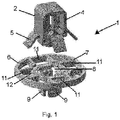
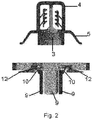
- FIGS 1 , 2 and 3 show an embodiment of a fastener 1 for mounting on a support, with the components thereof in a position prior to assembly.
- This fastener 1 comprises:
- Figure 1 also shows that the base 6 additionally comprises a plurality of holes 11 arranged around the central hollow 8, the holes 11 adjacent to the rotating legs 9 having a protrusion 12 projecting outwardly with respect to the central hollow 8, such that in a mounted position of the fastener 1 the flexible legs 5 are inserted into the holes 11 adjacent to the rotating legs 9, and the central part 4 of the body 2 with an axial hollow 3 is inserted into the central hollow 8 of the base 6.
- the central part 4 of the body 2 with an axial hollow 3 in the central hollow 8 of the base 6 the rotating legs 9 of the base 6 pass from a retracted position to an extended position.
- Figures 4 to 6 show different views of the elements of the fastener for mounting on a support of an embodiment of the invention at the beginning of the mounting thereof.
- the flexible legs 5 are inserted into the holes 11 adjacent to the rotating legs 9, and the central part 4 of the body 2 with an axial hollow 3 is inserted into the central hollow 8 of the base 6.
- the central part 4 of the body 2 with an axial hollow 3 comprises a plurality of sets of at least two teeth 14, and the main part 7 of the base 6 comprises a plurality of retention legs 15, such that each retention leg 15 is adapted to fit into the gaps 16 between the teeth 14 in each set of teeth 14.
- the retention legs 15 are in the gaps 16 between two teeth 14.
- Figures 7 and 8 show views of a fastener of an embodiment of the invention on a support, at the beginning of the mounting thereof, figure 8 showing a front view of figure 7 .
- Figure 5 shows a cross section of the elements of the fastener for mounting on a support of an embodiment of the invention at the beginning of the mounting thereof, and figure 9 shows said elements at the end of the mounting thereof.
- the rotating legs 9 pivot around the hinges 10 as the central part 4 of the body 2 with an axial hollow 3 is inserted into the central hollow 8 of the base 6, until reaching the final position, with the rotating legs arranged horizontally according to figure 9 .
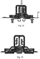
- Figures 10 to 13 show different views of a fastener of an embodiment of the invention on a support, at the end of the mounting thereof.
- the retention legs are above the last tooth 14, and the rotating legs are arranged horizontally, having pivoted around the hinge by the push of the central part 4 of the body 2.
- the assembly comprising the fastener 1 and the support 13 has a sandwich arrangement, the support 13 being placed between the rotating legs 9 and the protrusions 12 of the base 6 and the flexible legs 5 of the body 2 with an axial hollow 3 abutting the protrusions 12. This allows for a secure fastening of the fastener 1 on the support 13, preventing relative movement between both elements.
- the axial hollow 3 of the body 2 comprises two parts 17 with retaining means 18 for engaging the thread of a stud, to make the coupling of said stud with the fastener 1 possible.
- the fastener 1 is made of plastic.
Landscapes
- Engineering & Computer Science (AREA)
- General Engineering & Computer Science (AREA)
- Mechanical Engineering (AREA)
- Insertion Pins And Rivets (AREA)
- Clamps And Clips (AREA)
Abstract
Description
- The present invention relates to a fastener of the type used for the mounting thereof on a support.
- Different fastening devices provided with legs or elements for the fastening thereof to a panel are known.
- Document
FR 2776345 - Document
FR 2193749 - Document
EP 2047126 B1 describes a fastener that has a fastening foot that includes triangular shaped legs with support members for reinforcement and flaps, wherein the fastener is made of a molded plastic material. The legs pass from a retracted position to an extended position and make a hinge pivot due by deformation during the insertion of a plastic finger or rod (in other words, a pin in an elongated parallelepiped shape). The reinforcement members have a free end that butts up against the finger when the finger is inserted in the axial hollow in a locking position, such that the legs maintain an extended position. - Although these fastening devices are normally satisfactory, any improvement in the operation thereof constitutes significant progress.
- The object of the present invention is to therefore provide a fastener for mounting on a support that prevents the movement of the fastener on the support.
- The invention provides a fastener for mounting on a support that comprises:
- a body with an axial hollow, comprising a central part and a plurality of flexible legs arranged around the central part, and
- a base, comprising a main part with a central hollow from which a plurality of rotating legs project, each rotating leg being adapted to pivot around a hinge which connects the rotating leg to the main part of the base, each rotating leg being able to adopt a retracted position and an extended position, such that in the extended position the rotating leg has pivoted outwardly around the hinge with respect to the retracted position,
- By mounting the fastener on a support, the configuration of the fastener for mounting on a support of the invention allows the flexible legs of the body with an axial hollow to be in contact with the protrusions of the base and, by the support remaining in contact with the rotating legs and the protrusions of the base, a more secure fastening of the support is achieved.
- Other advantageous embodiments of the invention are presented in the dependent claims.
- Described below is an illustrative embodiment, which is by no means limiting, of the object of the present invention, referring to the attached drawings, in which:
-
Figure 1 shows a perspective view of the elements of the fastener for mounting on a support of an embodiment of the invention. -
Figure 2 shows cross-sectional view of the elements of the fastener for mounting on a support of an embodiment of the invention. -
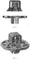
Figure 3 shows a cross-sectional view rotated 45° of the elements of the fastener for mounting on a support of an embodiment of the invention. -
Figure 4 shows a perspective view of the elements of the fastener for mounting on a support of an embodiment of the invention at the beginning of the mounting thereof. -
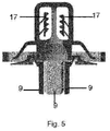
Figure 5 shows a cross-sectional view of the object offigure 4 . -
Figure 6 shows a cross-sectional view rotated 45° of the object offigure 4 . -
Figure 7 shows a perspective view of a fastener of an embodiment of the invention on a support, at the beginning of the mounting thereof. -
Figure 8 shows a front view offigure 7 . -
Figure 9 shows cross section of the elements of the fastener for mounting on a support of an embodiment of the invention at the end of the mounting thereof. -
Figures 10 to 13 show different views of a fastener of an embodiment of the invention on a support, at the end of the mounting thereof. -
Figures 1 ,2 and3 show an embodiment of a fastener 1 for mounting on a support, with the components thereof in a position prior to assembly. This fastener 1 comprises: - a
body 2 with anaxial hollow 3, comprising acentral part 4 and a plurality offlexible legs 5 arranged around thecentral part 4, and - a
base 6, comprising a main part 7 with acentral hollow 8 from which a plurality of rotatinglegs 9 project, each rotatingleg 9 being adapted to pivot around ahinge 10 which connects therotating leg 9 to the main part 7 of thebase 6, eachrotating leg 9 being able to adopt a retracted position and an extended position, such that in the extended position the rotatingleg 9 has pivoted outwardly around thehinge 10 with respect to the retracted position. -
Figure 1 also shows that thebase 6 additionally comprises a plurality ofholes 11 arranged around thecentral hollow 8, theholes 11 adjacent to the rotatinglegs 9 having aprotrusion 12 projecting outwardly with respect to thecentral hollow 8, such that in a mounted position of the fastener 1 theflexible legs 5 are inserted into theholes 11 adjacent to therotating legs 9, and thecentral part 4 of thebody 2 with anaxial hollow 3 is inserted into thecentral hollow 8 of thebase 6. This way, by inserting thecentral part 4 of thebody 2 with an axial hollow 3 in the central hollow 8 of thebase 6, therotating legs 9 of thebase 6 pass from a retracted position to an extended position. -
Figures 4 to 6 show different views of the elements of the fastener for mounting on a support of an embodiment of the invention at the beginning of the mounting thereof. One can see that theflexible legs 5 are inserted into theholes 11 adjacent to therotating legs 9, and thecentral part 4 of thebody 2 with anaxial hollow 3 is inserted into thecentral hollow 8 of thebase 6. - In
figure 5 one can see that thebody 2 has still not made contact with therotating legs 9, and thus said legs remain vertical in said figure. - In
figure 6 one can see that thecentral part 4 of thebody 2 with anaxial hollow 3 comprises a plurality of sets of at least twoteeth 14, and the main part 7 of thebase 6 comprises a plurality ofretention legs 15, such that eachretention leg 15 is adapted to fit into thegaps 16 between theteeth 14 in each set ofteeth 14. Infigure 6 one can see that theretention legs 15 are in thegaps 16 between twoteeth 14. -
Figures 7 and 8 show views of a fastener of an embodiment of the invention on a support, at the beginning of the mounting thereof,figure 8 showing a front view offigure 7 . -
Figure 5 shows a cross section of the elements of the fastener for mounting on a support of an embodiment of the invention at the beginning of the mounting thereof, andfigure 9 shows said elements at the end of the mounting thereof. As can be seen, therotating legs 9 pivot around thehinges 10 as thecentral part 4 of thebody 2 with anaxial hollow 3 is inserted into the central hollow 8 of thebase 6, until reaching the final position, with the rotating legs arranged horizontally according tofigure 9 . -
Figures 10 to 13 show different views of a fastener of an embodiment of the invention on a support, at the end of the mounting thereof. Infigure 10 one can see that the retention legs are above thelast tooth 14, and the rotating legs are arranged horizontally, having pivoted around the hinge by the push of thecentral part 4 of thebody 2. - This way, the assembly comprising the fastener 1 and the
support 13 has a sandwich arrangement, thesupport 13 being placed between therotating legs 9 and theprotrusions 12 of thebase 6 and theflexible legs 5 of thebody 2 with anaxial hollow 3 abutting theprotrusions 12. This allows for a secure fastening of the fastener 1 on thesupport 13, preventing relative movement between both elements. - In
figures 5 and6 one can also see that theaxial hollow 3 of thebody 2 comprises twoparts 17 withretaining means 18 for engaging the thread of a stud, to make the coupling of said stud with the fastener 1 possible. - Preferably, the fastener 1 is made of plastic.
- Although embodiments of the invention have been represented and described, it is evident that modifications comprised within the scope of the same can be introduced, the invention not being limited to said embodiments, rather only to the content of the following claims.
Claims (5)
- Fastener (1) for mounting on a support, comprising:- a body (2) with an axial hollow (3), comprising a central part (4) and a plurality of flexible legs (3) around the central part (4), and- a base (6), comprising a main part (7) with a central hollow (8) from which a plurality of rotating legs (9) project, each rotating leg (9) being adapted to pivot around a hinge (10) which connects the rotating leg (9) to the main part (7) of the base (6), each rotating leg (9) being able to adopt a retracted position and an extended position, such that in the extended position the rotating leg (9) has pivoted outwardly around the hinge (10) with respect to the retracted position,characterized in that
the base (6) additionally comprises a plurality of holes (11) around the central hollow (8), the holes (11) adjacent to the rotating legs (9) having a protrusion (12) projecting outwardly with respect to the central hollow (8),
such that in a mounted position of the fastener (1) the flexible legs (5) are inserted into the holes (11) adjacent to the rotating legs (9), and the central part (4) of the body (2) with an axial hollow (3) is inserted into the central hollow (8) of the base (6),
such that, on insertion of the central part (4) of the body (2) with an axial hollow (3) into the central hollow (8) of the base (6), the rotating legs (9) of the base (6) pass from the retracted position to the extended position. - Fastener (1) for mounting on a support according to claim 1, wherein when the fastener (1) is mounted on a support (13), the assembly comprising the fastener (1) and the support (13) has a sandwich arrangement, the support (13) being placed between the rotating legs (9) and the protrusions (12) of the base (6), and the flexible legs (5) of the body (2) with an axial hollow (3) abutting the protrusions (12).
- Fastener (1) for mounting on a support, according to any of the previous claims, wherein the central part (4) of the body (2) with an axial hollow (3) comprises a plurality of sets of at least two teeth (14), and the main part (7) of the base (6) comprises a plurality of retention legs (15), such that each retention leg (15) is adapted to fit into the gaps (16) between the teeth (14) in each set of teeth (14).
- Fastener (1) for mounting on a support, according to any of the previous claims, wherein the axial hollow (3) comprises two parts (17) with retaining means (18) for engaging the thread of a stud.
- Fastener (1) for mounting on a support, according to any of the previous claims, wherein the fastener (1) is made of plastic.
Applications Claiming Priority (1)
| Application Number | Priority Date | Filing Date | Title |
|---|---|---|---|
| ES201730646A ES2688107B2 (en) | 2017-04-28 | 2017-04-28 | FIXING FOR ASSEMBLY ON A SUPPORT |
Publications (1)
| Publication Number | Publication Date |
|---|---|
| EP3396181A1 true EP3396181A1 (en) | 2018-10-31 |
Family
ID=62002031
Family Applications (1)
| Application Number | Title | Priority Date | Filing Date |
|---|---|---|---|
| EP18167364.1A Withdrawn EP3396181A1 (en) | 2017-04-28 | 2018-04-13 | Fastener for mounting on a support |
Country Status (4)
| Country | Link |
|---|---|
| US (1) | US20180313385A1 (en) |
| EP (1) | EP3396181A1 (en) |
| CN (1) | CN108799288A (en) |
| ES (1) | ES2688107B2 (en) |
Citations (1)
| Publication number | Priority date | Publication date | Assignee | Title |
|---|---|---|---|---|
| US4890966A (en) * | 1987-08-07 | 1990-01-02 | Nifco, Inc. | Securing clip |
Family Cites Families (10)
| Publication number | Priority date | Publication date | Assignee | Title |
|---|---|---|---|---|
| JPH0452486Y2 (en) * | 1987-05-27 | 1992-12-10 | ||
| US5716161A (en) * | 1996-08-22 | 1998-02-10 | Ankara Industries, Inc. | Retainer clip |
| FR2904386B1 (en) * | 2006-07-31 | 2008-10-17 | I T W De France Soc Par Action | ATTACHE TO BE MOUNTED IN THE BLIND |
| GB0804196D0 (en) * | 2008-03-06 | 2008-04-16 | Newfrey Llc | Fastener for automotive components |
| US20100119325A1 (en) * | 2008-11-07 | 2010-05-13 | Edland David W | Stud retaining fastener assembly |
| FR3001006B1 (en) * | 2013-01-17 | 2015-03-13 | Illinois Tool Works | ARTICLE TO BE FIXED IN A BLIND ON A SUPPORT |
| DE202013005582U1 (en) * | 2013-06-21 | 2014-09-23 | Illinois Tool Works Inc. | System comprising a carrier component |
| FR3020099B1 (en) * | 2014-04-16 | 2017-08-18 | Illinois Tool Works | CLAMP FOR ATTACHING A PANEL TO A SUPPORT, METHOD FOR CARRYING OUT THE SAME, AND AUTOMOTIVE EQUIPMENT |
| DE102014214903A1 (en) * | 2014-07-30 | 2016-02-04 | Bayerische Motoren Werke Aktiengesellschaft | Fixing device for a sandwich component |
| JP6240060B2 (en) * | 2014-12-18 | 2017-11-29 | トヨタ自動車株式会社 | Temporary fastener and retainer for held member |
-
2017
- 2017-04-28 ES ES201730646A patent/ES2688107B2/en active Active
-
2018
- 2018-04-13 EP EP18167364.1A patent/EP3396181A1/en not_active Withdrawn
- 2018-04-23 US US15/959,574 patent/US20180313385A1/en not_active Abandoned
- 2018-04-28 CN CN201810398888.7A patent/CN108799288A/en active Pending
Patent Citations (1)
| Publication number | Priority date | Publication date | Assignee | Title |
|---|---|---|---|---|
| US4890966A (en) * | 1987-08-07 | 1990-01-02 | Nifco, Inc. | Securing clip |
Also Published As
| Publication number | Publication date |
|---|---|
| US20180313385A1 (en) | 2018-11-01 |
| ES2688107B2 (en) | 2019-07-10 |
| CN108799288A (en) | 2018-11-13 |
| ES2688107A1 (en) | 2018-10-30 |
Similar Documents
| Publication | Publication Date | Title |
|---|---|---|
| US7690876B2 (en) | Clip | |
| US7223045B2 (en) | Device and method for detachably connecting abutting structural parts and tie member for use to form said device | |
| EP3022475B1 (en) | Pipe clip with locking feature | |
| US9496692B2 (en) | Frame for cable feedthrough systems and frame parts therefor | |
| EP1375931B1 (en) | Two-piece clip | |
| KR20200085227A (en) | Grommet removal assemblies and methods | |
| US7207759B2 (en) | Fastener for panels or the like | |
| DE10217600B4 (en) | Wiper arm with cover | |
| US20040071526A1 (en) | Rivet provided with elastic feet | |
| US20130307390A1 (en) | Furniture part comprising a torque-transmitting shaft | |
| EP3810939B1 (en) | Fastening clip assemblies | |
| DE112013007042T5 (en) | Fastening device and hook part | |
| EP3050816B1 (en) | Pallet with safety elements | |
| CN109952441B (en) | Rivet fastener assembly | |
| US10221879B2 (en) | Panel mount fastener having an outer sleeve with a collapsible end portion | |
| DE202015005870U1 (en) | Two-piece plug-in coupling for connecting components | |
| JP6069322B2 (en) | Connector | |
| US9790976B2 (en) | Fastener | |
| US6074144A (en) | Fastener with retained movable pin | |
| KR20090007196A (en) | Fixing structure and hinge device of goods | |
| KR20210000863U (en) | One-touch coupler for rebar connection | |
| US20050152764A1 (en) | Fastener | |
| US20180313385A1 (en) | Fastener for mounting on a support | |
| CN105378304B (en) | For the tightening member being connected to transmission part on rod member | |
| EP3452733A1 (en) | Extension adapter of a plug-in coupling and associated production and installation method |
Legal Events
| Date | Code | Title | Description |
|---|---|---|---|
| PUAI | Public reference made under article 153(3) epc to a published international application that has entered the european phase |
Free format text: ORIGINAL CODE: 0009012 |
|
| STAA | Information on the status of an ep patent application or granted ep patent |
Free format text: STATUS: THE APPLICATION HAS BEEN PUBLISHED |
|
| AK | Designated contracting states |
Kind code of ref document: A1 Designated state(s): AL AT BE BG CH CY CZ DE DK EE ES FI FR GB GR HR HU IE IS IT LI LT LU LV MC MK MT NL NO PL PT RO RS SE SI SK SM TR |
|
| AX | Request for extension of the european patent |
Extension state: BA ME |
|
| STAA | Information on the status of an ep patent application or granted ep patent |
Free format text: STATUS: REQUEST FOR EXAMINATION WAS MADE |
|
| 17P | Request for examination filed |
Effective date: 20190423 |
|
| RBV | Designated contracting states (corrected) |
Designated state(s): AL AT BE BG CH CY CZ DE DK EE ES FI FR GB GR HR HU IE IS IT LI LT LU LV MC MK MT NL NO PL PT RO RS SE SI SK SM TR |
|
| GRAP | Despatch of communication of intention to grant a patent |
Free format text: ORIGINAL CODE: EPIDOSNIGR1 |
|
| STAA | Information on the status of an ep patent application or granted ep patent |
Free format text: STATUS: GRANT OF PATENT IS INTENDED |
|
| INTG | Intention to grant announced |
Effective date: 20190712 |
|
| STAA | Information on the status of an ep patent application or granted ep patent |
Free format text: STATUS: THE APPLICATION IS DEEMED TO BE WITHDRAWN |
|
| 18D | Application deemed to be withdrawn |
Effective date: 20191123 |