EP2047126B1 - Fastener for blind mounting - Google Patents
Fastener for blind mounting Download PDFInfo
- Publication number
- EP2047126B1 EP2047126B1 EP07789442A EP07789442A EP2047126B1 EP 2047126 B1 EP2047126 B1 EP 2047126B1 EP 07789442 A EP07789442 A EP 07789442A EP 07789442 A EP07789442 A EP 07789442A EP 2047126 B1 EP2047126 B1 EP 2047126B1
- Authority
- EP
- European Patent Office
- Prior art keywords
- finger
- leg
- fastener
- fastener according
- legs
- Prior art date
- Legal status (The legal status is an assumption and is not a legal conclusion. Google has not performed a legal analysis and makes no representation as to the accuracy of the status listed.)
- Active
Links
Images


Classifications
-
- F—MECHANICAL ENGINEERING; LIGHTING; HEATING; WEAPONS; BLASTING
- F16—ENGINEERING ELEMENTS AND UNITS; GENERAL MEASURES FOR PRODUCING AND MAINTAINING EFFECTIVE FUNCTIONING OF MACHINES OR INSTALLATIONS; THERMAL INSULATION IN GENERAL
- F16B—DEVICES FOR FASTENING OR SECURING CONSTRUCTIONAL ELEMENTS OR MACHINE PARTS TOGETHER, e.g. NAILS, BOLTS, CIRCLIPS, CLAMPS, CLIPS OR WEDGES; JOINTS OR JOINTING
- F16B19/00—Bolts without screw-thread; Pins, including deformable elements; Rivets
- F16B19/04—Rivets; Spigots or the like fastened by riveting
- F16B19/08—Hollow rivets; Multi-part rivets
- F16B19/10—Hollow rivets; Multi-part rivets fastened by expanding mechanically
- F16B19/1027—Multi-part rivets
- F16B19/1036—Blind rivets
- F16B19/1081—Blind rivets fastened by a drive-pin
Definitions
- the invention generally concerns fasteners for blind mounting on a panel provided with an opening.
- Such a fastener is known in particular from the document FR 2 776 345 which comprises a body of plastics material, having an axial hollow.
- the body comprises a collar for bearing on the periphery of the opening of a panel and a foot for holding the body on the panel adapted to pass into said opening.
- the foot comprises several legs, in particular holding legs, which, when not acted upon, are disposed in the form of a barrel.
- the fastener also comprises a finger adapted to be inserted into the hollow to lock the fastener to the panel. The insertion of the finger causes the separation of the free ends of the holding legs such that the fastener is clamped onto the panel which is held between the bearing collar and the free end of the legs of the holding legs.
- the clamping force is localized on the periphery of the opening of the panel and is exerted by the pressing of the holding legs against that periphery.
- the invention is directed to improving the performance of this type of fastener.
- the invention provides a fastener for blind mounting on a panel provided with an opening, comprising a body, of plastics material, having an axial hollow and comprising a collar for bearing on the periphery of said opening and a foot for holding said body on said panel adapted to pass into said opening, said fastener further comprising a finger adapted to be inserted into said hollow and to adopt a locking position in which said fastener is fixed to said panel, characterized in that said foot comprises two legs each comprising a flap and a brace member, each said flap being adapted to pivot around a hinge which connects it to the remainder of said foot, each said brace member of a respective said leg extending to a free end, each leg being able to adopt a retracted position in which its flap faces the flap of the other said leg and its brace member is oriented towards its hinge and towards the other said leg, its brace member being superposed with respect to the brace member of the other said leg between said flaps, and an extended position in which its flap has pi
- each leg pivots by deformation of the hinge which connects it to the rest of the foot.
- This deformation only requires a moderate pushing-in force, which facilitates the operations of putting in place of the fastener whether they be manual, or automated.
- the fastener With the legs being in their retracted position, the fastener is fixed onto the panel.
- the fastener 1 of molded plastics material comprises a finger 2 and a body 3.
- the finger 2 is a stud of elongate parallelepiped form. It comprises a first profiled portion 4 of square section. This portion 4 has a free end having an end surface 5. Near that surface 5, a channel 6 extends on the periphery of the portion 4.
- the finger 2 Remote from the free end, the finger 2 continues with a second portion 7.
- the portion 4 and the portion 7 are separated from each other by a channel 8 similar to the channel 6.
- the channels 6, 8 extend in parallel planes that are each transverse to the axial direction of the finger 2. This axial direction is parallel to the axis 9 of the finger 2.
- the finger 2 has axial symmetry about its axis 9.
- the portion 7 has a re-entrant longitudinal portion 10 on two of its opposite surfaces. Each re-entrant portion 10 extends over the whole length of the portion 7 and close to a longitudinal edge 11 of the surface to which the re-entrant portion 10 belongs.
- portion 7 having the re-entrant portion 10 each comprise a zone 13 set back with respect to a zone 14 situated between the re-entrant portion 10 and the edge 11.
- the zone 14 is much less wide than is the zone 13.
- Portion 7 comprises a free end 15 which is located remote from the free end 5.
- the edge formed between the surface of the free end 15 and each zone 13 is rounded.
- the general dimensions of the finger 2 in a plane transverse to the axis 9 correspond to the cross-section of the portion 4.
- the body 3 is a one-piece molding and comprises a head 20 and a foot 21.
- the body 3 has a main axis 22.
- the head 20 comprises two coaxial cylinder sections 23, 24 fixed to each other.
- the section 23 has a slightly greater diameter than the section 24 such that there is a shoulder 25 between the sections 23, 24.
- section 23 has a free surface 26. The edge formed between the surface 26 and the lateral surface of the section 23 is rounded.
- the head 20 is passed all the way through by a hollow 27 of square section of which the main longitudinal axis coincides with the axis 27 when the finger 2 is inserted in the hollow 27.
- the depth of the hollow 27 in the head 20 substantially corresponds to the length of the portion 7 of the finger 2.
- a groove 28 of semi-circular cross-section which extends in a plane transverse to the axis 22.
- This groove 28 corresponds to the male portion of a snap engagement system operating with a corresponding female portion.
- the female portion may be the channel 8 or the channel 6.
- the foot 21 further comprises a support 30 and legs 31.
- the legs 31 each comprise a flap 32 and a brace member 33.
- the legs 31 are connected to the support 30 by hinges 34.
- the support 30 is of square shape and is disposed against the section 24.
- the hollow 27 continues by passing through the support 30 until it opens at the opposite end to section 24 of the support 30.
- the support 30 is centered on the axis 22 and its sides are shorter than the diameter of the section 24.
- This bearing collar 35 has a circular outer edge and a square inner edge.
- Two hinges 34 emerge from along two of the opposite sides of the support 30 remote from the bearing collar 35.
- the hinge 34 is thin and extends over substantially the whole of the length of the side of the support 30. In the other direction, the hinge 34 extends parallel to the axis 22, over a length equivalent to the height of the support 30.
- the flap 32 extends onwards from the hinge 34.
- the flap 32 has an airplane wing section with an outer surface 40 and an inner surface 41.
- the outer surface 40 is convex and domed whereas the inner surface 41 is concave and also domed.
- the thickness of the flap is slightly greater adjacent the hinge 34.
- the brace member 33 emerges from the inner surface 41 of the flap 32.
- the brace member 33 extends in a half-space delimited by a plane P passing through the axis of the body 3 and transverse to the hinges 34.
- the brace member 33 comprises a main portion of thickness comparable with that of the flap 32. This portion emerges from the inner surface 41 of the flap 32 in the immediate vicinity of the hinge 34 and extends transversely with respect to the flap 32, that is to say towards the opposite flap 32.
- the brace member 33 next has a portion having a slanting direction with respect to the axis 22 while projecting towards the support 30. This portion is mainly situated between the hinges 34.
- the free end 45 of the brace member 33 has a bearing surface 46 disposed facing the support 30 and the head 20. This bearing surface 46 is transversely oriented with respect to the axis 22.
- the surface 46 is situated at the end of the hollow 27.
- the brace member 33 Adjacent the plane P, the brace member 33 has a reinforcement 47 in the form of a flange which extends from the free end 45 of the brace member 33 to the free end of the flap 32, such that in the plane including that reinforcement 47, the leg 31 has a substantially triangular shape of which one side belongs to the brace member 33 and a second side belongs to the flap 32.
- the brace member 33 has a lateral surface 50 situated in the same plane as a lateral surface of the hinge 34 and of the flap 32.
- the other brace member 33 is identical, each brace member 33 being the image of the other due to axial symmetry about the axis 22.
- the brace members 33 are superposed one behind the other and cross at the axis 22; a first brace member 33 is situated in front of the plane P whereas the second brace member 33 is situated behind that plane.
- the flap 32 and the brace member 33 maintain the same relative position as in the retracted position.
- the leg 31 as a whole has rotated through 90°, the outer surface 40 of the flap 32 being brought into face to face relationship with the bearing surface 35 with the hinge 34 folded on itself.
- the bearing surface 46 is then situated in a plane parallel to the axis 22.
- the legs 31 are in their retracted position ( Figure 1 ).
- the finger 2 is brought towards the hollow 27 by aligning the axes 9 and 22 such that the finger 2 may then be inserted into the square hollow 27.
- the set back zones 13 are oriented along planes parallel to the flaps 32.
- the finger 2 is then inserted in the hollow 27 until the rib 28 cooperates with the channel 8 ( Figure 3 ).
- the finger 2 is then in a pre-engaged position and the legs 31 are still in retracted position.
- the channel 8 and the groove 28 separate and move apart whereas the surface 15 comes into contact with the bearing surfaces 46 of the brace members 33.
- the brace members 33 transmit a thrust such that the brace members 33 withdraw by the folding of the hinges 34.
- the surface 46 slides along the rounded surface between the surface 15 and the zone 13 until the end of the surface 50 of the brace member 33 comes into contact with the re-entrant portion 10. During this movement, the hinges 34 fold and the legs 31 turn until, for each of them, the surface 46 is in contact with the zone 13 and until the leg 31 has thus turned through 90°.
- the surface 5 is then flush with surface 26; the finger 2 is snap engaged within the body 3 and the legs 31 are in their retracted position with the flaps 32 in face to face relationship with the bearing surfaces 35.
- the height of the finger 2 corresponds to the distance separating the surface 26 from the free end of a flap 32, in retracted position of the legs.
- the fastener 1 is molded in two pieces: the finger 2 and the body 3.
- the body 3 is molded with the legs in retracted position.
- the fastener 1 is adapted to be mounted on a panel 51 comprising a square opening 52 of which the dimensions correspond to those of the support 30.
- the finger 2 is placed first of all in the body 3 in the pre-engaged position of the finger 2.
- the legs 31 are then in the retracted position.
- the fastener 1 is pushed through the opening 52 of the panel 51, legs 31 first, until the bearing collar 35 comes to bear against the outer surface 53 of the panel 51.
- the finger 2 is then pushed which presses in as already set out such that the legs 31 come into their extended position with the outer surface 40 in contact with the opposite surface 54 to the surface 53 of the panel 51.
- the domed shape of the legs 31 adapts to panels of which the surfaces are not flat such that the fastener always remains well locked onto the panel 51 whatever the shape of its surface.
- the surface 5 is flush with the level of the surface 26 such that the finger 2 cannot be withdrawn from the body 3.
- the fastener 1 is not demountable.
- the fastener 1 When positioned on a panel of an automotive vehicle, the fastener 1, and more particularly the periphery of the section 24, serves for attaching the loop at the end of a cord connected to a parcel shelf.
- the parcel shelf covers the rear space of the trunk and pivots under the effect of the opening or closing of the hatch of the vehicle, the parcel shelf being pulled or released via the cord engaged on the fastener 1.
- the portion 107 of the finger 102 has a square section identical to that of the portion 104; there is no re-entrant portion.
- the edge situated between the surface 115 and the adjacent surfaces is rounded.
- the support 130 comprises the two portions situated between the section 124 and the hinges 134. Between these two portions, the support 130 is discontinuous and has two plates 136 of the same height as the rest of the support 130.
- Each plate 136 extends along the periphery of the hollow 127, they face each other and extend between the two support portions 130 without being connected thereto.
- each plate 136 On their inner surface 137, each plate 136 comprises a groove 138 which extends transversely to the axial direction of the body 103.
- Each groove 138 extends from an edge of the surface 137 towards the opposite edge over a distance slightly greater than half of the distance between those two opposite edges.
- Each groove 138 is disposed in face to face relationship to the portion of surface 137 of the opposite plate 136 not having any groove 138.
- each brace member 133 At its end 145 projecting from its surface 150, each brace member 133 comprises a tooth 160 which corresponds to a small parallelepiped protuberance.
- the grooves 138 are adapted to cooperate with the teeth 160 of the brace members 133. Each groove 138 cooperates with one of the two teeth 160 located facing that groove 138 in retracted position of the legs 131.
- the surface 137 Along its edge situated at its free end, the surface 137 has a chamfer 161 so as to form a snap engagement ramp for the tooth 160.
- the body 103 is molded with the legs 131 in their extended position, it being possible for the finger 102 to be formed as a one-piece molding with the body 103.
- the finger 102 is then positioned along the same axis as the body 103.
- Frangible bridges connect the finger 102 and the body 103 at the surface 126.
- the free end 115 is situated slightly to the exterior of the body 103.
- a mold part 162 may occupy the hollow 127 up to the level of the surface 115 of the finger 102 ( Figure 12 ).
- Slides 163 and two plates 164, 165 endowed with an aperture are provided to mold the legs 131, the support 130 and the sections 124, 123.
- the slides 163 are removed and then the plate 165.
- the body 103 is removed by passing the latter through the aperture of the plate 164. Due to the initial extended position of the legs 131 and the dimensions of the aperture of the plate 164 on the side provided for molding the support 130, when the body 103 is withdrawn, the legs 131 are constrained to rotate about their hinge 134. The passage of the legs 131 through the aperture is only possible once the legs are at 90° from the extended position, that is to say once the legs are in retracted position.
- the teeth 160 have come into contact with the plates 136 and more particularly with the chamfer 161 which they have climbed until snap engagement in the grooves 138.
- the legs 131 remain in their retracted position due to the snap engagement of the teeth 160 in the grooves 138.
- Locking of the fastener 101 on the panel 151 is carried out as before apart from the fact that when the finger 102 is molded with the body 103 along the axis of the body 103, it suffices to press on the finger 102 to break the frangible bridges and enable the finger 102 to push into the hollow 127 until it is in pre-engaged position of the finger 102. This step may be carried out prior to the use of the fastener 101 with the panel 151.
- the finger 102 comes to bear against the brace members 133, the effect of which is to disengage the teeth 160 from the grooves 138 and to rotate the legs 131 to their extended position.
- This rotation is all the more easy in that the extended position is the position in which the legs 131 were molded such that this position corresponds to a resting position of the legs 131 in which they are located spontaneously if there is no constraint of snap engagement type by the brace members 133 on the plates 136.
- the fastener 101 is here locked due to the fact of the presence of the finger 102 which, via the brace members 133, holds the flaps 132 against the panel 151 but also by the fact that this position corresponds to the molding position of the legs.
- a force exerted on the fastener 101 intended to make the legs 131 pass from their extended position to their retracted position is opposed by the holding force exerted by the finger 102 and the force of the legs 131 towards the extended position.
- the fastener 201 comprises a finger 202 and a body 203.
- the fastener 201 is of oblong general form.
- the head 220 comprises a bearing collar 235 having on one side a free surface 226.
- the bearing collar 235 extends annularly around the hollow 227. This collar 235 is slightly oriented towards the foot 221.
- An annular lateral wall 270 emerges from the opposite surface to the surface 226. The collar 235 and the wall 270 emerge from along the same oblong contour.
- the wall 270 comprises a support 230 extending in the direction of the axis 222 of the body 203 over a specific height of the same order of magnitude as the width of the bearing collar 235.
- the support 230 comprises two semi-cylindrical portions opposite to each other. At the opposite end of each semi-cylindrical portion to the bearing collar 235 extends a semi-frusto-conical portion 271. Each portion 271 is a half frustum cut by a plane passing through its axis.
- This portion 271 has a cut-out 272 extending over practically the whole height of the frustum, and emerging at the free end of the portion 271 so as to divide the portion onto two tabs 273 of the same dimensions.
- Each tab 273 is thus adapted to be slightly deformed.
- the two portions 271 face each other and emerge from the semi-cylindrical parts of the support 230.
- the support 230 has two straight portions of which the height is a little less. It is from these straight parts that the hinges 234 emerge, at the end of which are located the legs 231.
- the legs 231 face each other and the brace members 233, in retracted position of the legs, are each situated respectively on opposite sides of a median plane of the legs 231 passing through the axis 222.
- each leg 231 the body 203 comprises a cut-out 275.
- Each cut-out 275 extends from the flap 232 through the hinge 234 and up to the support part 230 and emerges at the surface 226.
- a drive lever 276 which is straight and of square section. It emerges from the surface 241 of the flap 232 and extends towards the surface 226 and slightly beyond it.
- the hollow 227 has an oblong cross-section transversely to the axis 222 which tends to retract progressively on going away from the surface 226 due to the existence of the portions 273.
- the finger 202 here comprises a head 277 comprising in the center a thick portion 278 having at the free surface end a blind hole 279 having a key-shaped cross-section.
- the free surface is extended by two jutting facets 280.
- a plate 281 of oblong form serving as a plate for abutment against the surface 226 of the foot 203 when the finger 202 is inserted into the body 203.
- the rest of the finger 202 which also has an oblong general form with two identical end pillars 282 opposite each other.
- the pillars 282 are each situated against a rectangular plate 299 which extends transversely to the plate 281 while emerging from that plate 281 and extending to the free end of the finger 202.
- first stage 283 which extends from the plate 281 and a second stage 284 which extends from the first stage 283.
- Each pillar 282 has, starting from the plate 281, an outer surface 285 of semi-frusto-conical form generally corresponding to the inner surface of the semi-frusto-conical part 271 of the foot 203.
- This surface 285 is continued by a semi-cylindrical surface which is interrupted by a first bead 286 and then towards the free end by a semi-annular rib 287 and lastly, right at the free end, by a second bead 288.
- the legs 231 have a reinforcement 247 but which is situated in the center with respect to the two lateral surfaces 250 of the brace members 233.
- the first stage 283 comprises two identical half stages disposed on respective opposite sides of a median plane 290 which is also a plane of symmetry with respect to which the two pillars 282 are images of each other.
- Each half stage has a rectangular cavity 291 which has a small recess 292 adjacent the plane 290 and the second stage 284.
- This cavity 291 is open to the outside via two opposite openings 293 and 294.
- the opening 293 has the same width as the drive lever 276.
- the opening 294 is wider than the opening 293 and less wide than the brace members 233. With regard to their height, the opening 294 has a height corresponding to the general height of the cavity 291 whereas the opening 293 is higher due to the fact that it extends adjacent the recess 292.
- the opening 293 of a half stage and the opening 294 of the other half stage extend side by side.
- the second stage 284 comprises a single wall 295 of stepped form, the re-entrant portion being located at the plane 290.
- the two facets of wall 295 on respective opposite sides of that re-entrant portion extend transversely to the plane 290.
- the height of the re-entrant portion is smaller than the width of the plates 299 such that the wall facets 295 are situated slightly set back with respect to the general dimensions of the plates 299.
- the facet of wall 295 furthest from the observer is the one situated under the opening 294 whereas the wall facet 295 closest to the observer is that situated under the opening 293.
- Each leg 231 is positioned in a recess delimited by a plate 299, a facet of wall 295 and the re-entrant portion situated between the two facets of wall 295.
- the brace members 233 When the finger 202 is inserted into the body 203, it is the bead 288 and the second stage 284 which enter the hollow 227 first. Due to the profile of stepped form, the brace members 233 initially meet no resistance such that the legs 231 remain in retracted position. With pushing in, the beads 288 come into contact with the inner surface of the semi-frusto-conical portions. By continued pushing in, the tabs 273 deform under the pressure of the beads 288 until these latter pass under the semi-frustoconical portions 271, the finger 202 then being snap engaged in a pre-engaged position in the body 203 with its legs 231 in retracted position. In this position, the end surfaces 246 of the brace members 233 are slightly away from the separation wall between the two stages 283, 284 ( Figure 18 ).
- the rib 287 pushes on the semi-frusto-conical portions 271 such that the tabs 273 deform and such that those ribs 287 pass under the portions 273.
- the separation wall between the stages 283, 284, and more particularly its surface adjacent the second stage 284 comes to bear against the surfaces 246 of the brace members 233 such that the legs 231 are constrained to turn about their hinge 234 until a rotation through 90° has been made.
- the legs 231 are in extended position and the finger 202 is inserted until the outer surface of the portions 285 comes into contact with the inner surface of the portions 271.
- the surface of the plate 281 situated adjacent the stages 283, 284 then comes against the free surface 226 of the body 203.
- the bead 286 and the rib 287 have symmetrical slopes such that it is possible for the bead 286 and the rib 287 to pass the tabs 273 in the opposite direction to that described above.
- the rotation is made possible by the fact that the free end 245 of the brace members 233 is already situated adjacent the second stage 284.
- the leg 231 then rotates through 90° which enables it to return to a retracted position.
- the free end 245 of the brace members 233 is then situated against one of the facets of wall 295 and this contact leads to rubbing when the extracting force is continued. This rubbing enables the leg 231 to be perfectly disposed in its retracted position and to avoid a certain slackening due to its disposition in extended position prior to this return to retracted position.
- the bead 288 on the other hand does not have a slope in the extraction direction such that in principle the finger 202 cannot be totally extracted from the body 203, the tabs 273 remaining blocked against the bead 288.
- the fastener can then be again placed on a panel through an opening thereof.
- the fastener 301 comprises a finger 302 similar to the finger 202 in that it has a head 377, a plate 381, a first stage 383 with cavities 391 and two openings 393 and 394 for each cavity 391, a second stage 384 and pillars 382 on respective opposite sides of the first and second stages 383, 384.
- the second stage 384 is also of stepped form with the two facets of wall 395 here being pierced such that they compose a support at the free end of the finger 302 which extends between the re-entrant portion forming wall and the pillars 382 and a rectangular protrusion which extends towards the first stage 383 partly filling the existing rectangular opening.
- the pillars 382 are straight in the zone corresponding to the first stage 383; they are of semi-cylindrical form with depressions of triangular cross-section over practically the whole of their height.
- the body 303 comprises a lateral wall 370 which extends starting from the collar 335 over a greater height than the combined heights of the support 330, the hinges 334 and the flaps 332 such that the hinges 334 and the flaps 332 are positioned in two windows of that wall. On respective opposite sides of each of those windows are two apertures 397 adapted to receive the studs 396.
- the wall 370 ends with a reduction in its cross-section with cut-outs 372 enabling a slight change in shape of the frustoconical portions 371 situated at the free end of the body 303.
- the insertion of the finger 302 is here guided by means of the stud 396 - aperture 397 systems. Moreover, the snap engagement 302 on the body 303 is only made when the finger 302 has reached the end of travel by the cooperation of the bead 388 with the portions 371.
- the fastener 401 comprises a body 403 having all the members of the body 203, as well as an annular wall 470 defining a window in which the legs 431 are positioned.
- the wall 470 also comprises windows in which the tabs 473 extend.
- the wall 470 retracts on approaching its free end. It has four square cut-outs 498 giving slight pliability to this wall part for the needs of snap engagement.
- This body 403 corresponds to the body 203 of which the support has been extended along a wall similar to the wall 370 of the body 303.
- the finger 402 comprises first and second stages 483, 484 identical to the stages 383, 384 of the finger 302.
- the pillars 482 are identical to the pillars 282.
Landscapes
- Engineering & Computer Science (AREA)
- General Engineering & Computer Science (AREA)
- Mechanical Engineering (AREA)
- Insertion Pins And Rivets (AREA)
- Vehicle Step Arrangements And Article Storage (AREA)
- Dowels (AREA)
- Orthopedics, Nursing, And Contraception (AREA)
Description
- The invention generally concerns fasteners for blind mounting on a panel provided with an opening.
- It is known that there are such fasteners provided with holding legs for them to be clamped to a panel.
- Such a fastener is known in particular from the
document FR 2 776 345 - The clamping force is localized on the periphery of the opening of the panel and is exerted by the pressing of the holding legs against that periphery.
- The document
FR2193749 claim 1. - The invention is directed to improving the performance of this type of fastener.
- To that end, the invention provides a fastener for blind mounting on a panel provided with an opening, comprising a body, of plastics material, having an axial hollow and comprising a collar for bearing on the periphery of said opening and a foot for holding said body on said panel adapted to pass into said opening, said fastener further comprising a finger adapted to be inserted into said hollow and to adopt a locking position in which said fastener is fixed to said panel, characterized in that said foot comprises two legs each comprising a flap and a brace member, each said flap being adapted to pivot around a hinge which connects it to the remainder of said foot, each said brace member of a respective said leg extending to a free end, each leg being able to adopt a retracted position in which its flap faces the flap of the other said leg and its brace member is oriented towards its hinge and towards the other said leg, its brace member being superposed with respect to the brace member of the other said leg between said flaps, and an extended position in which its flap has pivoted outwardly with respect to said retracted position, said legs passing from said retracted position to said extended position on insertion of said finger into said body, said free end of each brace member abutting said finger when it is inserted into said hollow in said locking position, by virtue of which each said leg is held in the extended position.
- On pushing in of the finger into the hollow of the body, by pressing the finger on the end of the brace members, each leg pivots by deformation of the hinge which connects it to the rest of the foot. This deformation only requires a moderate pushing-in force, which facilitates the operations of putting in place of the fastener whether they be manual, or automated. With the legs being in their retracted position, the fastener is fixed onto the panel.
- If the fastener is subjected to extraction forces, these will be applied from the panel onto the flaps of which the position is locked by the presence of the finger and of the brace members which extend between the finger and the flaps. The retaining force obtained is thus particularly high. This makes it possible to prevent a possible extraction of the fastener by pulling out the body.
- According to features of implementation that are particularly simple and convenient both with respect to manufacture and use:
- said brace members are situated on respective opposite sides of a median plane that is transverse to said flaps; and/or
- for each said leg, said free end is situated in the vicinity of the hinge of the other said leg in its retracted position; and/or
- at its said free end, each said brace member has a bearing surface transverse to the axial direction of said hollow when said legs are in their retracted position, said finger coming to bear on those said surfaces when it is inserted into said body; and/or
- on each said flap, the opposite surface to the surface from which said brace member extends is convex and bulge-shaped; and/or
- said finger has two longitudinal shoulders situated on two opposite surfaces and adapted to guide the translational movement of said free ends during the insertion of said finger into said body; and/or
- said foot comprises means for retaining said legs in retracted position; and possibly
- said retaining means comprise two plates facing each other and situated on the periphery of said hollow, each said plate being situated transversely and between the two said legs in retracted position; and possibly
- said retaining means further comprise a tooth on each said brace member and a re-entrant portion on each said plate by virtue of which each said brace member is adapted to snap engage with a respective said plate; and/or
- its said legs are in extended position in the absence of urging; and/or
- said finger is of plastics material; and/or
- said body has a head comprising said collar and a surface having an opening to which said hollow leads and, when said finger is inserted into said hollow, the surface of said finger at the same end as said head is substantially flush with said surface of said head; and/or
- said foot comprises an annular wall extending from said collar and delimiting said hollow; and possibly
- the fastener comprises means for snap engagement of said finger in said body, the snap engagement means comprising a bead on said finger and a frusto-conical portion of said annular wall, said portion being deformable to allow the passage of said bead on inserting said foot; and/or
- each said leg further comprises a lever for driving from the extended position to the retracted position, said lever extending in a cut-out of said flap and emerging from a portion of said hinge, said lever extending in the plane of said flap, transversely to said hinge and beyond it; and possibly
- said finger comprises facing each said leg a recess of which one wall is adapted, on withdrawal of said foot, to drive said lever towards the retracted position of said leg and/or
- each said flap is situated, in said retracted position, in a window cut out from said annular wall; and/or
- said finger comprises a stud and said annular wall comprises an aperture extending in the axial direction of said body, said aperture and said stud being adapted to guide the translational movement of said finger in said body.
- The features and advantages of the invention will appear from the following description, given by way of preferred but non-limiting example, with reference to the accompanying drawings in which:
-
Figure 1 is a perspective view of the fastener according to the invention, the finger not being inserted into the body; -
Figure 2 is a view in elevation of the fastener ofFigure 1 with the finger partially inserted into the body; -
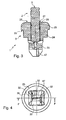
Figure 3 is a section view of that fastener on III-II offigure 2 ; -
Figure 4 is a plan view from the foot end of the body; -
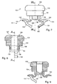
Figure 5 is a view in elevation of the fastener which, on the left side, represents the finger partially inserted and the leg in retracted position, and; on the right side, the finger in locking position and the leg in extended position, and on which the body portions from the direction of viewing have been cut away to show the whole of the finger; -
Figure 6 is a perspective view of a first variant of the fastener according to the invention, this fastener comprising two plates between its legs, for holding the legs in retracted position, the finger not being inserted into the body; -
Figure 7 is a view in elevation of the body of that fastener, the legs being in extended position; -
Figure 8 is a section view of that fastener on VIII-VIII offigure 7 ; -
Figure 9 is a section view of that fastener on IX-IX offigure 8 ; -
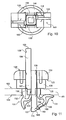
Figure 10 is a plan view from the foot end of the body of that fastener; -
Figure 11 is a view similar to that ofFigure 5 for the fastener shown inFigures 6 to 10 ; -
Figure 12 is a diagrammatic section view of the mold with the molded fastener; -
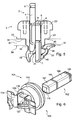
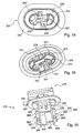
Figure 13 is a perspective view of an other variant of the fastener according to the invention, each of its legs comprising a lever for driving that leg from its extended position to its retracted position, the finger and the body comprising mutual snap engagement means; -
Figure 14 is a perspective view of the body of that fastener viewed from the bearing collar side ; -
Figure 15 is a perspective view of the body of that fastener viewed from the foot end; -
Figure 16 is a perspective view of the finger of that fastener; -
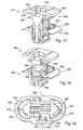
Figure 17 is a section view in perspective of that fastener on XVII-XVII offigure 13 ; -
Figure 18 is a section view in perspective of that fastener on XVIII-XVIII offigure 13 ; -
Figure 19 is a section view in perspective of that fastener on XIX-XIX offigure 13 ; -
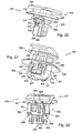
Figure 20 is a perspective view of that fastener with the legs in extended position; -
Figure 21 is a perspective view of another variant of the fastener with the finger partially inserted; -
Figure 22 is a perspective view of the finger of that fastener; -
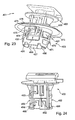
Figure 23 is a perspective view of another variant of the fastener with the finger partially inserted; and -
Figure 24 is a perspective view of the finger of that fastener. - The
fastener 1 of molded plastics material comprises afinger 2 and abody 3. - The
finger 2 is a stud of elongate parallelepiped form. It comprises a first profiledportion 4 of square section. Thisportion 4 has a free end having anend surface 5. Near thatsurface 5, achannel 6 extends on the periphery of theportion 4. - Remote from the free end, the
finger 2 continues with asecond portion 7. Theportion 4 and theportion 7 are separated from each other by achannel 8 similar to thechannel 6. - The
channels finger 2. This axial direction is parallel to theaxis 9 of thefinger 2. Thefinger 2 has axial symmetry about itsaxis 9. - The
portion 7 has a re-entrantlongitudinal portion 10 on two of its opposite surfaces. Eachre-entrant portion 10 extends over the whole length of theportion 7 and close to alongitudinal edge 11 of the surface to which there-entrant portion 10 belongs. - The surfaces of
portion 7 having there-entrant portion 10 each comprise azone 13 set back with respect to azone 14 situated between there-entrant portion 10 and theedge 11. Thezone 14 is much less wide than is thezone 13. -
Portion 7 comprises afree end 15 which is located remote from thefree end 5. The edge formed between the surface of thefree end 15 and eachzone 13 is rounded. - Despite the existence of the set back
zones 13, the general dimensions of thefinger 2 in a plane transverse to theaxis 9 correspond to the cross-section of theportion 4. - The
body 3 is a one-piece molding and comprises ahead 20 and afoot 21. Thebody 3 has amain axis 22. - The
head 20 comprises twocoaxial cylinder sections section 23 has a slightly greater diameter than thesection 24 such that there is ashoulder 25 between thesections shoulder 25,section 23 has afree surface 26. The edge formed between thesurface 26 and the lateral surface of thesection 23 is rounded. - The
head 20 is passed all the way through by a hollow 27 of square section of which the main longitudinal axis coincides with theaxis 27 when thefinger 2 is inserted in the hollow 27. The depth of the hollow 27 in thehead 20 substantially corresponds to the length of theportion 7 of thefinger 2. - On the periphery of the hollow 27, in the vicinity of the opening by which it emerges at the
surface 26, is agroove 28 of semi-circular cross-section which extends in a plane transverse to theaxis 22. Thisgroove 28 corresponds to the male portion of a snap engagement system operating with a corresponding female portion. The female portion may be thechannel 8 or thechannel 6. - The
foot 21 further comprises asupport 30 andlegs 31. - The
legs 31 each comprise aflap 32 and abrace member 33. Thelegs 31 are connected to thesupport 30 by hinges 34. - The
support 30 is of square shape and is disposed against thesection 24. The hollow 27 continues by passing through thesupport 30 until it opens at the opposite end tosection 24 of thesupport 30. - The
support 30 is centered on theaxis 22 and its sides are shorter than the diameter of thesection 24. - Between the
support 30 and the lateral surface of thesection 24 there is a bearingcollar 35 formed by the shoulder which separates thatsupport 30 and the lateral surface of thesection 24. This bearingcollar 35 has a circular outer edge and a square inner edge. - Two hinges 34 emerge from along two of the opposite sides of the
support 30 remote from the bearingcollar 35. - A
leg 31 with ahinge 34 will now be described. - The
hinge 34 is thin and extends over substantially the whole of the length of the side of thesupport 30. In the other direction, thehinge 34 extends parallel to theaxis 22, over a length equivalent to the height of thesupport 30. - As can be seen in
Figures 1 and 2 , theflap 32 extends onwards from thehinge 34. - The
flap 32 has an airplane wing section with anouter surface 40 and aninner surface 41. Theouter surface 40 is convex and domed whereas theinner surface 41 is concave and also domed. The thickness of the flap is slightly greater adjacent thehinge 34. - The
brace member 33 emerges from theinner surface 41 of theflap 32. - The
brace member 33 extends in a half-space delimited by a plane P passing through the axis of thebody 3 and transverse to thehinges 34. - The
brace member 33 comprises a main portion of thickness comparable with that of theflap 32. This portion emerges from theinner surface 41 of theflap 32 in the immediate vicinity of thehinge 34 and extends transversely with respect to theflap 32, that is to say towards theopposite flap 32. Thebrace member 33 next has a portion having a slanting direction with respect to theaxis 22 while projecting towards thesupport 30. This portion is mainly situated between the hinges 34. - Lastly, the
free end 45 of thebrace member 33 has a bearingsurface 46 disposed facing thesupport 30 and thehead 20. This bearingsurface 46 is transversely oriented with respect to theaxis 22. - The
surface 46 is situated at the end of the hollow 27. - Adjacent the plane P, the
brace member 33 has areinforcement 47 in the form of a flange which extends from thefree end 45 of thebrace member 33 to the free end of theflap 32, such that in the plane including thatreinforcement 47, theleg 31 has a substantially triangular shape of which one side belongs to thebrace member 33 and a second side belongs to theflap 32. - At the opposite side of the plane P, the
brace member 33 has alateral surface 50 situated in the same plane as a lateral surface of thehinge 34 and of theflap 32. - The
other brace member 33 is identical, eachbrace member 33 being the image of the other due to axial symmetry about theaxis 22. For an observer who looks at thebody 3 in the direction represented inFigure 2 , thebrace members 33 are superposed one behind the other and cross at theaxis 22; afirst brace member 33 is situated in front of the plane P whereas thesecond brace member 33 is situated behind that plane. - In
Figures 1 and 2 , thelegs 31 are disposed in a retracted position. - On the right side of
Figure 5 is represented the extended position of aleg 31 with thefinger 2 inserted into the hollow 27 in its locking position. - In this position, the
flap 32 and thebrace member 33 maintain the same relative position as in the retracted position. Theleg 31 as a whole has rotated through 90°, theouter surface 40 of theflap 32 being brought into face to face relationship with the bearingsurface 35 with thehinge 34 folded on itself. The bearingsurface 46 is then situated in a plane parallel to theaxis 22. - The insertion of the
finger 2 in thebody 3 will now be described. - When the
finger 2 is out of thebody 3, thelegs 31 are in their retracted position (Figure 1 ). Thefinger 2 is brought towards the hollow 27 by aligning theaxes finger 2 may then be inserted into the square hollow 27. The set backzones 13 are oriented along planes parallel to theflaps 32. Thefinger 2 is then inserted in the hollow 27 until therib 28 cooperates with the channel 8 (Figure 3 ). Thefinger 2 is then in a pre-engaged position and thelegs 31 are still in retracted position. - When insertion of the
finger 2 is continued, thechannel 8 and thegroove 28 separate and move apart whereas thesurface 15 comes into contact with the bearing surfaces 46 of thebrace members 33. By continuing to push on thefinger 2, thebrace members 33 transmit a thrust such that thebrace members 33 withdraw by the folding of the hinges 34. - The
surface 46 slides along the rounded surface between thesurface 15 and thezone 13 until the end of thesurface 50 of thebrace member 33 comes into contact with there-entrant portion 10. During this movement, thehinges 34 fold and thelegs 31 turn until, for each of them, thesurface 46 is in contact with thezone 13 and until theleg 31 has thus turned through 90°. - It is possible to continue to insert the
finger 2 with thebrace member 33 being guided along there-entrant portion 10 and which cannot therefore slip transversely up to theedge 11 and beyond it. This would lead to the passage of thebrace member 33 against the adjacent surface of thefinger 2 and the return of theleg 31 in a position close to the retracted position. - The insertion continues until the
channel 6 comes into contact with therib 28 and they cooperate by snap engagement. - The
surface 5 is then flush withsurface 26; thefinger 2 is snap engaged within thebody 3 and thelegs 31 are in their retracted position with theflaps 32 in face to face relationship with the bearing surfaces 35. The height of thefinger 2 corresponds to the distance separating thesurface 26 from the free end of aflap 32, in retracted position of the legs. - The
fastener 1 is molded in two pieces: thefinger 2 and thebody 3. Thebody 3 is molded with the legs in retracted position. - The
fastener 1 is adapted to be mounted on a panel 51 comprising asquare opening 52 of which the dimensions correspond to those of thesupport 30. - For the mounting of the
fastener 1 on the panel 51, thefinger 2 is placed first of all in thebody 3 in the pre-engaged position of thefinger 2. Thelegs 31 are then in the retracted position. - The
fastener 1 is pushed through theopening 52 of the panel 51,legs 31 first, until the bearingcollar 35 comes to bear against theouter surface 53 of the panel 51. - The
finger 2 is then pushed which presses in as already set out such that thelegs 31 come into their extended position with theouter surface 40 in contact with theopposite surface 54 to thesurface 53 of the panel 51. - The domed shape of the
legs 31 adapts to panels of which the surfaces are not flat such that the fastener always remains well locked onto the panel 51 whatever the shape of its surface. - In the embodiment shown, when the
finger 2 is engaged in its locking position and thefastener 1 is fixed onto the panel 51, thesurface 5 is flush with the level of thesurface 26 such that thefinger 2 cannot be withdrawn from thebody 3. Thefastener 1 is not demountable. - If it is attempted to pull off the fastener, a force is exerted from the
surface 54 onto thesurfaces 40 of theflaps 32. This force is transmitted via thebrace members 33 to thefinger 2. Due to the presence of thefinger 2, thelegs 31 cannot fold back onto retracted position. Furthermore, as theflaps 32 are wide, the pressure which is exerted on theflaps 32 is distributed over the whole width, which also ensures good retainment on the panel 51. - When positioned on a panel of an automotive vehicle, the
fastener 1, and more particularly the periphery of thesection 24, serves for attaching the loop at the end of a cord connected to a parcel shelf. The parcel shelf covers the rear space of the trunk and pivots under the effect of the opening or closing of the hatch of the vehicle, the parcel shelf being pulled or released via the cord engaged on thefastener 1. - With reference to
Figures 6 to 11 , a fastener according to a variant embodiment will now be described. - For this variant, the same numerical references as earlier have been kept for similar parts, increased by the number 100.
- The
portion 107 of thefinger 102 has a square section identical to that of theportion 104; there is no re-entrant portion. The edge situated between thesurface 115 and the adjacent surfaces is rounded. - The
support 130 comprises the two portions situated between thesection 124 and thehinges 134. Between these two portions, thesupport 130 is discontinuous and has twoplates 136 of the same height as the rest of thesupport 130. - Each
plate 136 extends along the periphery of the hollow 127, they face each other and extend between the twosupport portions 130 without being connected thereto. - On their
inner surface 137, eachplate 136 comprises agroove 138 which extends transversely to the axial direction of thebody 103. - Each
groove 138 extends from an edge of thesurface 137 towards the opposite edge over a distance slightly greater than half of the distance between those two opposite edges. - Each
groove 138 is disposed in face to face relationship to the portion ofsurface 137 of theopposite plate 136 not having anygroove 138. - At its
end 145 projecting from itssurface 150, eachbrace member 133 comprises atooth 160 which corresponds to a small parallelepiped protuberance. - The
grooves 138 are adapted to cooperate with theteeth 160 of thebrace members 133. Eachgroove 138 cooperates with one of the twoteeth 160 located facing thatgroove 138 in retracted position of thelegs 131. - Along its edge situated at its free end, the
surface 137 has achamfer 161 so as to form a snap engagement ramp for thetooth 160. - The
body 103 is molded with thelegs 131 in their extended position, it being possible for thefinger 102 to be formed as a one-piece molding with thebody 103. - The
finger 102 is then positioned along the same axis as thebody 103. Frangible bridges connect thefinger 102 and thebody 103 at thesurface 126. Thefree end 115 is situated slightly to the exterior of thebody 103. - Since the
legs 131 are molded in extended position, amold part 162 may occupy the hollow 127 up to the level of thesurface 115 of the finger 102 (Figure 12 ).Slides 163 and twoplates legs 131, thesupport 130 and thesections - To strip the
fastener 1 from the mold, theslides 163 are removed and then theplate 165. - Next, the
body 103 is removed by passing the latter through the aperture of theplate 164. Due to the initial extended position of thelegs 131 and the dimensions of the aperture of theplate 164 on the side provided for molding thesupport 130, when thebody 103 is withdrawn, thelegs 131 are constrained to rotate about theirhinge 134. The passage of thelegs 131 through the aperture is only possible once the legs are at 90° from the extended position, that is to say once the legs are in retracted position. - At the end of rotation, the
teeth 160 have come into contact with theplates 136 and more particularly with thechamfer 161 which they have climbed until snap engagement in thegrooves 138. - Once the
body 103 has been stripped from the mold, thelegs 131 remain in their retracted position due to the snap engagement of theteeth 160 in thegrooves 138. - Locking of the
fastener 101 on thepanel 151 is carried out as before apart from the fact that when thefinger 102 is molded with thebody 103 along the axis of thebody 103, it suffices to press on thefinger 102 to break the frangible bridges and enable thefinger 102 to push into the hollow 127 until it is in pre-engaged position of thefinger 102. This step may be carried out prior to the use of thefastener 101 with thepanel 151. - When the
surface 115 comes into contact with thesurfaces 146 of thebrace members 133, thefinger 102 comes to bear against thebrace members 133, the effect of which is to disengage theteeth 160 from thegrooves 138 and to rotate thelegs 131 to their extended position. This rotation is all the more easy in that the extended position is the position in which thelegs 131 were molded such that this position corresponds to a resting position of thelegs 131 in which they are located spontaneously if there is no constraint of snap engagement type by thebrace members 133 on theplates 136. - The
fastener 101 is here locked due to the fact of the presence of thefinger 102 which, via thebrace members 133, holds theflaps 132 against thepanel 151 but also by the fact that this position corresponds to the molding position of the legs. Thus, a force exerted on thefastener 101 intended to make thelegs 131 pass from their extended position to their retracted position is opposed by the holding force exerted by thefinger 102 and the force of thelegs 131 towards the extended position. - A description will now be given of another variant of the embodiment illustrated in
Figures 13 to 20 . For this variant, the same numerical references as before have been kept for similar parts, increased by the number 200 with respect to the numerical references of the fastener shown inFigures 1 to 5 . - The
fastener 201 comprises afinger 202 and abody 203. Thefastener 201 is of oblong general form. - The
head 220 comprises abearing collar 235 having on one side afree surface 226. Thebearing collar 235 extends annularly around the hollow 227. Thiscollar 235 is slightly oriented towards thefoot 221. An annularlateral wall 270 emerges from the opposite surface to thesurface 226. Thecollar 235 and thewall 270 emerge from along the same oblong contour. - The
wall 270 comprises asupport 230 extending in the direction of the axis 222 of thebody 203 over a specific height of the same order of magnitude as the width of thebearing collar 235. - The
support 230 comprises two semi-cylindrical portions opposite to each other. At the opposite end of each semi-cylindrical portion to thebearing collar 235 extends a semi-frusto-conical portion 271. Eachportion 271 is a half frustum cut by a plane passing through its axis. - This
portion 271 has a cut-out 272 extending over practically the whole height of the frustum, and emerging at the free end of theportion 271 so as to divide the portion onto twotabs 273 of the same dimensions. Eachtab 273 is thus adapted to be slightly deformed. - The two
portions 271 face each other and emerge from the semi-cylindrical parts of thesupport 230. - Between these semi-cylindrical parts, the
support 230 has two straight portions of which the height is a little less. It is from these straight parts that thehinges 234 emerge, at the end of which are located thelegs 231. - The
legs 231 face each other and thebrace members 233, in retracted position of the legs, are each situated respectively on opposite sides of a median plane of thelegs 231 passing through the axis 222. - At each
leg 231 thebody 203 comprises a cut-out 275. Each cut-out 275 extends from theflap 232 through thehinge 234 and up to thesupport part 230 and emerges at thesurface 226. - In the cut-out 275, there extends a
drive lever 276 which is straight and of square section. It emerges from thesurface 241 of theflap 232 and extends towards thesurface 226 and slightly beyond it. - The hollow 227 has an oblong cross-section transversely to the axis 222 which tends to retract progressively on going away from the
surface 226 due to the existence of theportions 273. - The
finger 202 here comprises ahead 277 comprising in the center athick portion 278 having at the free surface end ablind hole 279 having a key-shaped cross-section. The free surface is extended by two juttingfacets 280. - Under this
portion 278, there extends aplate 281 of oblong form serving as a plate for abutment against thesurface 226 of thefoot 203 when thefinger 202 is inserted into thebody 203. From the other side of the thatplate 281 with respect toportion 278, extends the rest of thefinger 202 which also has an oblong general form with twoidentical end pillars 282 opposite each other. Thepillars 282 are each situated against arectangular plate 299 which extends transversely to theplate 281 while emerging from thatplate 281 and extending to the free end of thefinger 202. - Between the two
pillars 282 there extends a portion having afirst stage 283 which extends from theplate 281 and asecond stage 284 which extends from thefirst stage 283. - Each
pillar 282 has, starting from theplate 281, anouter surface 285 of semi-frusto-conical form generally corresponding to the inner surface of the semi-frusto-conical part 271 of thefoot 203. Thissurface 285 is continued by a semi-cylindrical surface which is interrupted by afirst bead 286 and then towards the free end by asemi-annular rib 287 and lastly, right at the free end, by asecond bead 288. - The
legs 231 have areinforcement 247 but which is situated in the center with respect to the twolateral surfaces 250 of thebrace members 233. - The
first stage 283 comprises two identical half stages disposed on respective opposite sides of amedian plane 290 which is also a plane of symmetry with respect to which the twopillars 282 are images of each other. Each half stage has arectangular cavity 291 which has asmall recess 292 adjacent theplane 290 and thesecond stage 284. Thiscavity 291 is open to the outside via twoopposite openings opening 293 has the same width as thedrive lever 276. Theopening 294 is wider than theopening 293 and less wide than thebrace members 233. With regard to their height, theopening 294 has a height corresponding to the general height of thecavity 291 whereas theopening 293 is higher due to the fact that it extends adjacent therecess 292. On one face of thefirst stage 283, theopening 293 of a half stage and theopening 294 of the other half stage extend side by side. - The
second stage 284 comprises asingle wall 295 of stepped form, the re-entrant portion being located at theplane 290. The two facets ofwall 295 on respective opposite sides of that re-entrant portion extend transversely to theplane 290. The height of the re-entrant portion is smaller than the width of theplates 299 such that thewall facets 295 are situated slightly set back with respect to the general dimensions of theplates 299. - For an observer who looks at the
finger 202 in a direction of observation such as that ofFigure 16 , the facet ofwall 295 furthest from the observer is the one situated under theopening 294 whereas thewall facet 295 closest to the observer is that situated under theopening 293. - Each
leg 231 is positioned in a recess delimited by aplate 299, a facet ofwall 295 and the re-entrant portion situated between the two facets ofwall 295. - The use of the
fastener 201 will now be described. - When the
finger 202 is inserted into thebody 203, it is thebead 288 and thesecond stage 284 which enter the hollow 227 first. Due to the profile of stepped form, thebrace members 233 initially meet no resistance such that thelegs 231 remain in retracted position. With pushing in, thebeads 288 come into contact with the inner surface of the semi-frusto-conical portions. By continued pushing in, thetabs 273 deform under the pressure of thebeads 288 until these latter pass under thesemi-frustoconical portions 271, thefinger 202 then being snap engaged in a pre-engaged position in thebody 203 with itslegs 231 in retracted position. In this position, the end surfaces 246 of thebrace members 233 are slightly away from the separation wall between the twostages 283, 284 (Figure 18 ). - By continued pushing on the
finger 202, therib 287 pushes on the semi-frusto-conical portions 271 such that thetabs 273 deform and such that thoseribs 287 pass under theportions 273. At the same time, the separation wall between thestages second stage 284 comes to bear against thesurfaces 246 of thebrace members 233 such that thelegs 231 are constrained to turn about theirhinge 234 until a rotation through 90° has been made. - During this rotational movement, the end part of the
lever 276 does not hinder the rotation of theleg 231 about thehinge 234 since that end then directly enters into acavity 291 delimited by anopening 293. - The insertion of the
finger 202 continues until thebead 286 comes into contact with the inner surfaces of the semi-frusto-conical portions 271. The snap engagement then occurs in the same way as for thebeads 288. - At this stage, the
legs 231 are in extended position and thefinger 202 is inserted until the outer surface of theportions 285 comes into contact with the inner surface of theportions 271. The surface of theplate 281 situated adjacent thestages free surface 226 of thebody 203. - By contrast to the fasteners described earlier, here the free surface of the finger and the free surface 228 are not flush.
- It is possible to demount the
fastener 1; by exerting a pull on thefinger 202, it is driven in an extraction direction opposite to the preceding direction of insertion, thelegs 231 being in extended position. - The
bead 286 and therib 287 have symmetrical slopes such that it is possible for thebead 286 and therib 287 to pass thetabs 273 in the opposite direction to that described above. Concerning thelegs 231, when thedrive lever 276 reaches the back of thecavity 291 and more particularly the back of therecess 292, the back of the recess presses on the end of thelever 276 such that the latter is rotated and with it the whole of theleg 231. The rotation is made possible by the fact that thefree end 245 of thebrace members 233 is already situated adjacent thesecond stage 284. - The
leg 231 then rotates through 90° which enables it to return to a retracted position. Thefree end 245 of thebrace members 233 is then situated against one of the facets ofwall 295 and this contact leads to rubbing when the extracting force is continued. This rubbing enables theleg 231 to be perfectly disposed in its retracted position and to avoid a certain slackening due to its disposition in extended position prior to this return to retracted position. - The
bead 288 on the other hand does not have a slope in the extraction direction such that in principle thefinger 202 cannot be totally extracted from thebody 203, thetabs 273 remaining blocked against thebead 288. - The fastener can then be again placed on a panel through an opening thereof.
- With reference to
Figure 21 , another variant of the embodiment will now be described. For this variant, the same numerical references as before have been kept for similar parts, increased by the number 100 with respect to the numerical references of the fastener shown inFigures 13 to 20 . - The
fastener 301 comprises afinger 302 similar to thefinger 202 in that it has ahead 377, aplate 381, afirst stage 383 withcavities 391 and twoopenings cavity 391, asecond stage 384 andpillars 382 on respective opposite sides of the first andsecond stages - The
second stage 384 is also of stepped form with the two facets of wall 395 here being pierced such that they compose a support at the free end of thefinger 302 which extends between the re-entrant portion forming wall and thepillars 382 and a rectangular protrusion which extends towards thefirst stage 383 partly filling the existing rectangular opening. Thepillars 382 are straight in the zone corresponding to thefirst stage 383; they are of semi-cylindrical form with depressions of triangular cross-section over practically the whole of their height. - At the
second stage 384, the pillars have a semi-frusto-conical outer surface of which the cross-section diminishes towards the free end of thefoot 382. On each surface there are disposed twocircular studs 396. Thesestuds 396 jut slightly beyond the general dimensions of thepillars 382. Lastly, thepillars 382 end with abead 388. - The
body 303 comprises alateral wall 370 which extends starting from thecollar 335 over a greater height than the combined heights of the support 330, thehinges 334 and theflaps 332 such that thehinges 334 and theflaps 332 are positioned in two windows of that wall. On respective opposite sides of each of those windows are twoapertures 397 adapted to receive thestuds 396. Thewall 370 ends with a reduction in its cross-section with cut-outs 372 enabling a slight change in shape of thefrustoconical portions 371 situated at the free end of thebody 303. - With respect to the preceding variant, the insertion of the
finger 302 is here guided by means of the stud 396 -aperture 397 systems. Moreover, thesnap engagement 302 on thebody 303 is only made when thefinger 302 has reached the end of travel by the cooperation of thebead 388 with theportions 371. - With reference to
Figures 23, 24 , still another variant of the embodiment is now described for which the numerical references are the same for similar parts, and are increased by the figure 100 with respect to the numerical references of the fastener represented inFigures 21, 22 and by 200 with respect to the numerical references of the fastener represented inFigures 13 to 20 . - The
fastener 401 comprises abody 403 having all the members of thebody 203, as well as anannular wall 470 defining a window in which thelegs 431 are positioned. Thewall 470 also comprises windows in which thetabs 473 extend. Thewall 470 retracts on approaching its free end. It has four square cut-outs 498 giving slight pliability to this wall part for the needs of snap engagement. Thisbody 403 corresponds to thebody 203 of which the support has been extended along a wall similar to thewall 370 of thebody 303. - The
finger 402 comprises first andsecond stages stages finger 302. Thepillars 482 are identical to thepillars 282. - The present invention is not limited to the embodiment described and shown but encompasses any variant execution thereof.
Claims (18)
- A fastener for blind mounting on a panel (51, 151) provided with an opening (52, 152), comprising a body (3, 103, 203, 303, 403), of plastics material, having an axial hollow (27, 127, 227, 327, 427) and comprising a collar (35, 135, 235, 335, 435) for bearing on the periphery of said opening (52, 152) and a foot (21, 121, 221) for holding said body (3, 103, 203, 303, 403) on said panel (51, 151) adapted to pass into said opening (52, 152), said fastener (1, 101, 201, 301, 401) further comprising a finger (2, 102, 202, 302, 402) adapted to be inserted into said hollow (27, 127, 227, 327, 427) and to adopt a locking position in which said fastener (1, 101, 201, 301, 401) is fixed to said panel (51, 151), wherein that said foot (21, 121, 221) comprises two legs (31, 131, 231, 331, 431) each comprising a brace member (33, 133, 233), being adapted to pivot around a hinge (34, 134, 234, 334, 434) which connects it to the remainder of said foot (21, 121, 221), each said brace member (33, 133, 233) of a respective said leg (31, 131, 231, 331, 431) extending to a free end (45, 145, 245), each leg (31, 131, 231, 331, 431) being able to adopt a retracted position and an extended position in which its flap (32, 132, 232, 332, 432) has pivoted outwardly with respect to said retracted position, said legs (31, 131, 231, 331, 431) passing from said retracted position to said extended position on insertion of said finger (2, 102, 202, 302, 402) into said body (3, 103, 203, 303, 403), said free end (45, 145, 245) of each brace member (33, 133, 233) abutting said finger (2, 102, 202, 302, 402) when it is inserted into said hollow (27, 127, 227, 327, 427) in said locking position, by virtue of which each said leg (31, 131, 231, 331, 431) is held in the extended position, characterized in that each leg comprises a flap (32, 132, 232, 332, 432) each leg (31, 131, 231, 331, 431) being able to adopt a retracted position in which its flap (32, 132, 232, 332, 432) faces the flap (32, 132, 232, 332, 432) of the other said leg (31, 131, 231, 331, 431) and its brace member (33,133, 233) is oriented towards its hinge (34, 134, 234, 334, 434) and towards the other said leg (31, 131, 231, 331, 431), its brace member (33, 133, 233) being superposed with respect to the brace member (33, 133, 233) of the other said leg (31, 131, 231, 331, 431) between said flaps (32, 132, 232, 332, 432).
- A fastener according to claim 1, characterized in that said brace members (33, 133, 233) are situated on respective opposite sides of a median plane (P) that is transverse to said flaps (32, 132, 232, 332, 432).
- A fastener according to any one of claims 1 or 2, characterized in that for each said leg (31, 131, 231, 331, 431), said free end (45, 145, 245) is situated in the vicinity of the hinge (34, 134, 234, 334, 434) of the other said leg (31, 131, 231, 331, 431) in its retracted position.
- A fastener according to any one of claims 1 to 3, characterized in that at its said free end (45, 145, 245), each said brace member (33, 133, 233) has a bearing surface (46, 146, 246) transverse to the axial direction of said hollow (27, 127, 227, 327, 427) when said legs (31, 131, 231, 331, 431) are in their retracted position, said finger (2, 102, 202, 302, 402) coming to bear on those said surfaces (46, 146, 246) when it is inserted into said body (3, 103, 203, 303, 403).
- A fastener according to any one of claim 1 to 4, characterized in that on each said flap (32, 132, 232, 332, 432), the opposite surface (40) to the surface (41) from which said brace member (33, 133, 233) extends is convex and bulge-shaped.
- A fastener according to any one of claims 1 to 5, characterized in that said finger (2) has two longitudinal shoulders (10) situated on two opposite surfaces and adapted to guide the translational movement of said free ends (45) during the insertion of said finger (2) into said body (3).
- A fastener according to any one of claims 1 to 6, characterized in that said foot (121) comprises means for retaining said legs (131) in retracted position.
- A fastener according to claim 7, characterized in that said retaining means comprise two plates (136) facing each other and situated on the periphery of said hollow (127), each said plate (136) being situated transversely and between the two said legs (131) in retracted position.
- A fastener according to claim 8, characterized in that said retaining means further comprise a tooth (160) on each said brace member (133) and a re-entrant portion (138) on each said plate (136) by virtue of which each said brace member (133) is adapted to snap engage with a respective said plate (136).
- A fastener according to any one of claims 7 to 9, characterized in that its said legs (131) are in extended position in the absence of urging.
- A fastener according to any one of claims 1 to 10, characterized in that said finger (2, 102, 202, 302, 402) is of plastics material.
- A fastener according to any one of claims 1 to 11, characterized in that said body (3, 103) has a head (20, 120) comprising said collar (35, 135) and a surface (26, 126) having an opening to which said hollow (27, 127) leads and in that, when said finger (2, 102) is inserted into said hollow (27, 127), the surface (5, 105) at the end of said finger (2, 102) at the same end as said head (20, 120) is substantially flush with said surface (26, 126) of said head (20, 120).
- A fastener according to any one of claims 1 to 12, characterized in that said foot (221, 321, 421) comprises an annular wall (270, 370, 470) extending from said collar (235, 335, 435) and delimiting said hollow (227, 327, 427).
- A fastener according to claim 13, characterized in that it comprises means for snap engagement of said finger (202, 302, 402) in said body, the snap engagement means comprising a bead (288, 388, 488) on said finger (202, 302, 402) and a frusto-conical portion (271, 371, 471) of said annular wall (270, 370, 470), said portion (271, 371, 471) being deformable to allow the passage of said bead (288, 388, 488) on inserting said foot (202, 302, 402).
- A fastener according to any one of claims 13 or 14, characterized in that each said leg (231, 331, 431) further comprises a lever (276, 376, 476) for driving from the extended position to the retracted position, said lever (276, 376, 476) extending in a cut-out (275, 375, 475) of said flap (232, 332, 432) and emerging from a portion of said hinge (234, 334, 434), said lever (276, 376, 476) extending in the plane of said flap (232, 332, 432), transversely to said hinge (234, 334, 434) and beyond it.
- A fastener according to claim 15, characterized in that said finger (202, 302, 402) comprises facing each said leg (231, 331, 431) a recess (292, 392, 492) of which one wall is adapted, on withdrawal of said finger (202, 302, 402), to drive said lever (276, 376, 476) towards the retracted position of said leg (231, 331, 431).
- A fastener according to any one of claims 13 to 16, characterized in that each said flap (332, 432) is situated, in said retracted position, in a window cut out from said annular wall (370, 470).
- A fastener according to any one of claims 13 to 17, characterized in that said finger (302) comprises a stud (396) and said annular wall (370) comprises an aperture (397) extending in the axial direction of said body (303), said aperture (397) and said stud (396) being adapted to guide the translational movement of said finger (302) in said body (303).
Applications Claiming Priority (2)
| Application Number | Priority Date | Filing Date | Title |
|---|---|---|---|
| FR0653210A FR2904386B1 (en) | 2006-07-31 | 2006-07-31 | ATTACHE TO BE MOUNTED IN THE BLIND |
| PCT/IB2007/001730 WO2008015511A1 (en) | 2006-07-31 | 2007-06-25 | Fastener for blind mounting |
Publications (2)
| Publication Number | Publication Date |
|---|---|
| EP2047126A1 EP2047126A1 (en) | 2009-04-15 |
| EP2047126B1 true EP2047126B1 (en) | 2010-08-04 |
Family
ID=37762642
Family Applications (1)
| Application Number | Title | Priority Date | Filing Date |
|---|---|---|---|
| EP07789442A Active EP2047126B1 (en) | 2006-07-31 | 2007-06-25 | Fastener for blind mounting |
Country Status (6)
| Country | Link |
|---|---|
| EP (1) | EP2047126B1 (en) |
| JP (1) | JP5324443B2 (en) |
| CN (1) | CN101460748B (en) |
| DE (1) | DE602007008250D1 (en) |
| FR (1) | FR2904386B1 (en) |
| WO (1) | WO2008015511A1 (en) |
Cited By (2)
| Publication number | Priority date | Publication date | Assignee | Title |
|---|---|---|---|---|
| EP2722534A4 (en) * | 2012-07-30 | 2015-05-06 | Toyota Motor Co Ltd | FIXING MEANS, FIXING MEANS FOR EXTRACTING STRUCTURE, AND DEVICE FOR FASTENING A CURTAIN IN CURTAIN |
| FR3121484A1 (en) * | 2021-03-31 | 2022-10-07 | Illinois Tool Works | FASTENING SET FOR DETACHABLE ASSEMBLY OF A PANEL TO A STRUCTURE |
Families Citing this family (6)
| Publication number | Priority date | Publication date | Assignee | Title |
|---|---|---|---|---|
| JP5214310B2 (en) * | 2008-04-15 | 2013-06-19 | トヨタ車体株式会社 | Deck side trim mounting structure |
| DE102009014678A1 (en) | 2009-03-25 | 2010-09-30 | A.Raymond Et Cie | Spreizniet |
| IT1397287B1 (en) * | 2009-12-01 | 2013-01-04 | Illinois Tool Works | SELF-LOCKING ACCESSORY FOR A VEHICLE BODY PART. |
| FR3020099B1 (en) | 2014-04-16 | 2017-08-18 | Illinois Tool Works | CLAMP FOR ATTACHING A PANEL TO A SUPPORT, METHOD FOR CARRYING OUT THE SAME, AND AUTOMOTIVE EQUIPMENT |
| ES2688107B2 (en) * | 2017-04-28 | 2019-07-10 | A Raymond Et Cie | FIXING FOR ASSEMBLY ON A SUPPORT |
| CN109764315A (en) * | 2019-03-15 | 2019-05-17 | 豪尔赛科技集团股份有限公司 | A kind of fixation device and lamp installation method for small space lamp installation |
Family Cites Families (9)
| Publication number | Priority date | Publication date | Assignee | Title |
|---|---|---|---|---|
| US3188905A (en) * | 1962-04-03 | 1965-06-15 | David I Millet | Fastening device with pivotal locking means |
| JPS5335509B2 (en) * | 1972-07-26 | 1978-09-27 | ||
| JPS58151708U (en) * | 1982-04-07 | 1983-10-11 | 株式会社ニフコ | Fastener |
| JPS6087741U (en) * | 1983-11-19 | 1985-06-17 | 加藤発条株式会社 | Glove box opening restriction stopper |
| JPH0422088Y2 (en) * | 1987-08-07 | 1992-05-20 | ||
| FR2805503B1 (en) * | 2000-02-28 | 2002-05-31 | Itw De France | SHUTTER FOR AN OPENING MADE IN A SHEET |
| JP2004316856A (en) * | 2003-04-18 | 2004-11-11 | Piolax Inc | Clip and its manufacturing method |
| JP2005351462A (en) * | 2004-06-14 | 2005-12-22 | Nifco Inc | Clip |
| FR2873771B1 (en) * | 2004-07-30 | 2008-08-15 | I T W De France Sas | FEMALE FITTING AND SHUTTER COMPRISING THE SAME |
-
2006
- 2006-07-31 FR FR0653210A patent/FR2904386B1/en not_active Expired - Fee Related
-
2007
- 2007-06-25 EP EP07789442A patent/EP2047126B1/en active Active
- 2007-06-25 DE DE602007008250T patent/DE602007008250D1/en active Active
- 2007-06-25 CN CN200780020388XA patent/CN101460748B/en not_active Expired - Fee Related
- 2007-06-25 WO PCT/IB2007/001730 patent/WO2008015511A1/en not_active Ceased
- 2007-06-25 JP JP2009522349A patent/JP5324443B2/en not_active Expired - Fee Related
Cited By (2)
| Publication number | Priority date | Publication date | Assignee | Title |
|---|---|---|---|---|
| EP2722534A4 (en) * | 2012-07-30 | 2015-05-06 | Toyota Motor Co Ltd | FIXING MEANS, FIXING MEANS FOR EXTRACTING STRUCTURE, AND DEVICE FOR FASTENING A CURTAIN IN CURTAIN |
| FR3121484A1 (en) * | 2021-03-31 | 2022-10-07 | Illinois Tool Works | FASTENING SET FOR DETACHABLE ASSEMBLY OF A PANEL TO A STRUCTURE |
Also Published As
| Publication number | Publication date |
|---|---|
| JP5324443B2 (en) | 2013-10-23 |
| FR2904386B1 (en) | 2008-10-17 |
| DE602007008250D1 (en) | 2010-09-16 |
| CN101460748A (en) | 2009-06-17 |
| CN101460748B (en) | 2011-01-19 |
| FR2904386A1 (en) | 2008-02-01 |
| WO2008015511A1 (en) | 2008-02-07 |
| EP2047126A1 (en) | 2009-04-15 |
| JP2009545711A (en) | 2009-12-24 |
Similar Documents
| Publication | Publication Date | Title |
|---|---|---|
| EP2047126B1 (en) | Fastener for blind mounting | |
| US10443643B2 (en) | Fastening device with high pull-out strength | |
| US6668424B1 (en) | Snap-in assist grip and assembly method | |
| US4556351A (en) | Expansion rivet assembly | |
| EP1260719B1 (en) | Removable and reusable fastener | |
| US20090056087A1 (en) | Clip | |
| EP2766615B1 (en) | Fastening device for fastening a panel to a wall with a high resistance to pulling off and assembly comprising such a device | |
| US4085651A (en) | Plastic fastener | |
| EP3388693B1 (en) | Clip | |
| US11572026B2 (en) | Fastener | |
| US8950631B2 (en) | Securing collar and dispenser comprising such a collar | |
| CN105579651A (en) | Device for fastening an object on a support plate and obtained assembly | |
| US20100232903A1 (en) | Clip | |
| CA2425209C (en) | Blind fastener | |
| US20070102605A1 (en) | Arrangement and method for fitting a brake assist device in a motor vehicle | |
| JP2010144830A (en) | Fastener | |
| US20100129143A1 (en) | Fastener for detachably connecting a profile to a counterprofile | |
| CN111664153A (en) | Rivet type fastener | |
| WO2010089709A1 (en) | Article to fix on a support provided with an opening and assist grip handle comprising it | |
| JP3828955B2 (en) | Grommet | |
| EP3490847B1 (en) | Body molding and method of applying an accent strip to a body molding | |
| CN2723754Y (en) | Mechanical lock fastening type self-plugging rivet | |
| JP2003120628A (en) | Article fixing clip | |
| JP2024079951A (en) | Fastener | |
| JP7569711B2 (en) | Vehicle interior structure |
Legal Events
| Date | Code | Title | Description |
|---|---|---|---|
| PUAI | Public reference made under article 153(3) epc to a published international application that has entered the european phase |
Free format text: ORIGINAL CODE: 0009012 |
|
| 17P | Request for examination filed |
Effective date: 20081216 |
|
| AK | Designated contracting states |
Kind code of ref document: A1 Designated state(s): AT BE BG CH CY CZ DE DK EE ES FI FR GB GR HU IE IS IT LI LT LU LV MC MT NL PL PT RO SE SI SK TR |
|
| AX | Request for extension of the european patent |
Extension state: AL BA HR MK RS |
|
| DAX | Request for extension of the european patent (deleted) | ||
| RBV | Designated contracting states (corrected) |
Designated state(s): DE ES FR GB IT SE |
|
| GRAP | Despatch of communication of intention to grant a patent |
Free format text: ORIGINAL CODE: EPIDOSNIGR1 |
|
| GRAS | Grant fee paid |
Free format text: ORIGINAL CODE: EPIDOSNIGR3 |
|
| GRAA | (expected) grant |
Free format text: ORIGINAL CODE: 0009210 |
|
| AK | Designated contracting states |
Kind code of ref document: B1 Designated state(s): DE ES FR GB IT SE |
|
| REG | Reference to a national code |
Ref country code: GB Ref legal event code: FG4D |
|
| REF | Corresponds to: |
Ref document number: 602007008250 Country of ref document: DE Date of ref document: 20100916 Kind code of ref document: P |
|
| PG25 | Lapsed in a contracting state [announced via postgrant information from national office to epo] |
Ref country code: SE Free format text: LAPSE BECAUSE OF FAILURE TO SUBMIT A TRANSLATION OF THE DESCRIPTION OR TO PAY THE FEE WITHIN THE PRESCRIBED TIME-LIMIT Effective date: 20100804 |
|
| PLBE | No opposition filed within time limit |
Free format text: ORIGINAL CODE: 0009261 |
|
| STAA | Information on the status of an ep patent application or granted ep patent |
Free format text: STATUS: NO OPPOSITION FILED WITHIN TIME LIMIT |
|
| PG25 | Lapsed in a contracting state [announced via postgrant information from national office to epo] |
Ref country code: ES Free format text: LAPSE BECAUSE OF FAILURE TO SUBMIT A TRANSLATION OF THE DESCRIPTION OR TO PAY THE FEE WITHIN THE PRESCRIBED TIME-LIMIT Effective date: 20101115 |
|
| 26N | No opposition filed |
Effective date: 20110506 |
|
| REG | Reference to a national code |
Ref country code: DE Ref legal event code: R097 Ref document number: 602007008250 Country of ref document: DE Effective date: 20110506 |
|
| GBPC | Gb: european patent ceased through non-payment of renewal fee |
Effective date: 20110625 |
|
| PG25 | Lapsed in a contracting state [announced via postgrant information from national office to epo] |
Ref country code: IT Free format text: LAPSE BECAUSE OF NON-PAYMENT OF DUE FEES Effective date: 20110625 |
|
| PG25 | Lapsed in a contracting state [announced via postgrant information from national office to epo] |
Ref country code: GB Free format text: LAPSE BECAUSE OF NON-PAYMENT OF DUE FEES Effective date: 20110625 |
|
| REG | Reference to a national code |
Ref country code: FR Ref legal event code: PLFP Year of fee payment: 9 |
|
| REG | Reference to a national code |
Ref country code: FR Ref legal event code: PLFP Year of fee payment: 10 |
|
| PGFP | Annual fee paid to national office [announced via postgrant information from national office to epo] |
Ref country code: DE Payment date: 20160628 Year of fee payment: 10 |
|
| REG | Reference to a national code |
Ref country code: FR Ref legal event code: PLFP Year of fee payment: 11 |
|
| REG | Reference to a national code |
Ref country code: DE Ref legal event code: R119 Ref document number: 602007008250 Country of ref document: DE |
|
| PG25 | Lapsed in a contracting state [announced via postgrant information from national office to epo] |
Ref country code: DE Free format text: LAPSE BECAUSE OF NON-PAYMENT OF DUE FEES Effective date: 20180103 |
|
| REG | Reference to a national code |
Ref country code: FR Ref legal event code: PLFP Year of fee payment: 12 |
|
| P01 | Opt-out of the competence of the unified patent court (upc) registered |
Effective date: 20231101 |
|
| PGFP | Annual fee paid to national office [announced via postgrant information from national office to epo] |
Ref country code: FR Payment date: 20250625 Year of fee payment: 19 |