EP3396156B1 - Verfahren zur steuerung eines windparks und windpark - Google Patents
Verfahren zur steuerung eines windparks und windpark Download PDFInfo
- Publication number
- EP3396156B1 EP3396156B1 EP18020138.6A EP18020138A EP3396156B1 EP 3396156 B1 EP3396156 B1 EP 3396156B1 EP 18020138 A EP18020138 A EP 18020138A EP 3396156 B1 EP3396156 B1 EP 3396156B1
- Authority
- EP
- European Patent Office
- Prior art keywords
- local
- disturbance
- controller
- wind farm
- farm
- Prior art date
- Legal status (The legal status is an assumption and is not a legal conclusion. Google has not performed a legal analysis and makes no representation as to the accuracy of the status listed.)
- Active
Links
Images
Classifications
-
- H—ELECTRICITY
- H02—GENERATION; CONVERSION OR DISTRIBUTION OF ELECTRIC POWER
- H02J—ELECTRIC POWER NETWORKS; CIRCUIT ARRANGEMENTS OR SYSTEMS FOR SUPPLYING OR DISTRIBUTING ELECTRIC POWER; SYSTEMS FOR STORING ELECTRIC ENERGY
- H02J3/00—Circuit arrangements for AC mains or AC distribution networks
- H02J3/12—Arrangements for adjusting voltage in AC networks by changing a characteristic of the network load
- H02J3/16—Arrangements for adjusting voltage in AC networks by changing a characteristic of the network load by adjustment of reactive power
-
- F—MECHANICAL ENGINEERING; LIGHTING; HEATING; WEAPONS; BLASTING
- F03—MACHINES OR ENGINES FOR LIQUIDS; WIND, SPRING, OR WEIGHT MOTORS; PRODUCING MECHANICAL POWER OR A REACTIVE PROPULSIVE THRUST, NOT OTHERWISE PROVIDED FOR
- F03D—WIND MOTORS
- F03D7/00—Controlling wind motors
- F03D7/02—Controlling wind motors the wind motors having rotation axis substantially parallel to the air flow entering the rotor
- F03D7/028—Controlling wind motors the wind motors having rotation axis substantially parallel to the air flow entering the rotor controlling wind motor output power
- F03D7/0284—Controlling wind motors the wind motors having rotation axis substantially parallel to the air flow entering the rotor controlling wind motor output power in relation to the state of the electric grid
-
- F—MECHANICAL ENGINEERING; LIGHTING; HEATING; WEAPONS; BLASTING
- F03—MACHINES OR ENGINES FOR LIQUIDS; WIND, SPRING, OR WEIGHT MOTORS; PRODUCING MECHANICAL POWER OR A REACTIVE PROPULSIVE THRUST, NOT OTHERWISE PROVIDED FOR
- F03D—WIND MOTORS
- F03D7/00—Controlling wind motors
- F03D7/02—Controlling wind motors the wind motors having rotation axis substantially parallel to the air flow entering the rotor
- F03D7/04—Automatic control; Regulation
- F03D7/042—Automatic control; Regulation by means of an electrical or electronic controller
-
- F—MECHANICAL ENGINEERING; LIGHTING; HEATING; WEAPONS; BLASTING
- F03—MACHINES OR ENGINES FOR LIQUIDS; WIND, SPRING, OR WEIGHT MOTORS; PRODUCING MECHANICAL POWER OR A REACTIVE PROPULSIVE THRUST, NOT OTHERWISE PROVIDED FOR
- F03D—WIND MOTORS
- F03D7/00—Controlling wind motors
- F03D7/02—Controlling wind motors the wind motors having rotation axis substantially parallel to the air flow entering the rotor
- F03D7/04—Automatic control; Regulation
- F03D7/042—Automatic control; Regulation by means of an electrical or electronic controller
- F03D7/047—Automatic control; Regulation by means of an electrical or electronic controller characterised by the controller architecture, e.g. multiple processors or data communications
-
- F—MECHANICAL ENGINEERING; LIGHTING; HEATING; WEAPONS; BLASTING
- F03—MACHINES OR ENGINES FOR LIQUIDS; WIND, SPRING, OR WEIGHT MOTORS; PRODUCING MECHANICAL POWER OR A REACTIVE PROPULSIVE THRUST, NOT OTHERWISE PROVIDED FOR
- F03D—WIND MOTORS
- F03D7/00—Controlling wind motors
- F03D7/02—Controlling wind motors the wind motors having rotation axis substantially parallel to the air flow entering the rotor
- F03D7/04—Automatic control; Regulation
- F03D7/042—Automatic control; Regulation by means of an electrical or electronic controller
- F03D7/048—Automatic control; Regulation by means of an electrical or electronic controller controlling wind farms
-
- H—ELECTRICITY
- H02—GENERATION; CONVERSION OR DISTRIBUTION OF ELECTRIC POWER
- H02J—ELECTRIC POWER NETWORKS; CIRCUIT ARRANGEMENTS OR SYSTEMS FOR SUPPLYING OR DISTRIBUTING ELECTRIC POWER; SYSTEMS FOR STORING ELECTRIC ENERGY
- H02J3/00—Circuit arrangements for AC mains or AC distribution networks
- H02J3/18—Arrangements for adjusting, eliminating or compensating reactive power in networks
-
- H—ELECTRICITY
- H02—GENERATION; CONVERSION OR DISTRIBUTION OF ELECTRIC POWER
- H02J—ELECTRIC POWER NETWORKS; CIRCUIT ARRANGEMENTS OR SYSTEMS FOR SUPPLYING OR DISTRIBUTING ELECTRIC POWER; SYSTEMS FOR STORING ELECTRIC ENERGY
- H02J3/00—Circuit arrangements for AC mains or AC distribution networks
- H02J3/38—Arrangements for feeding a single network from two or more generators or sources in parallel; Arrangements for feeding already energised networks from additional generators or sources in parallel
- H02J3/381—Dispersed generators
-
- H—ELECTRICITY
- H02—GENERATION; CONVERSION OR DISTRIBUTION OF ELECTRIC POWER
- H02J—ELECTRIC POWER NETWORKS; CIRCUIT ARRANGEMENTS OR SYSTEMS FOR SUPPLYING OR DISTRIBUTING ELECTRIC POWER; SYSTEMS FOR STORING ELECTRIC ENERGY
- H02J3/00—Circuit arrangements for AC mains or AC distribution networks
- H02J3/38—Arrangements for feeding a single network from two or more generators or sources in parallel; Arrangements for feeding already energised networks from additional generators or sources in parallel
- H02J3/46—Controlling the sharing of generated power between the generators, sources or networks
-
- F—MECHANICAL ENGINEERING; LIGHTING; HEATING; WEAPONS; BLASTING
- F05—INDEXING SCHEMES RELATING TO ENGINES OR PUMPS IN VARIOUS SUBCLASSES OF CLASSES F01-F04
- F05B—INDEXING SCHEME RELATING TO WIND, SPRING, WEIGHT, INERTIA OR LIKE MOTORS, TO MACHINES OR ENGINES FOR LIQUIDS COVERED BY SUBCLASSES F03B, F03D AND F03G
- F05B2220/00—Application
- F05B2220/70—Application in combination with
- F05B2220/706—Application in combination with an electrical generator
-
- F—MECHANICAL ENGINEERING; LIGHTING; HEATING; WEAPONS; BLASTING
- F05—INDEXING SCHEMES RELATING TO ENGINES OR PUMPS IN VARIOUS SUBCLASSES OF CLASSES F01-F04
- F05B—INDEXING SCHEME RELATING TO WIND, SPRING, WEIGHT, INERTIA OR LIKE MOTORS, TO MACHINES OR ENGINES FOR LIQUIDS COVERED BY SUBCLASSES F03B, F03D AND F03G
- F05B2240/00—Components
- F05B2240/90—Mounting on supporting structures or systems
- F05B2240/96—Mounting on supporting structures or systems as part of a wind turbine farm
-
- F—MECHANICAL ENGINEERING; LIGHTING; HEATING; WEAPONS; BLASTING
- F05—INDEXING SCHEMES RELATING TO ENGINES OR PUMPS IN VARIOUS SUBCLASSES OF CLASSES F01-F04
- F05B—INDEXING SCHEME RELATING TO WIND, SPRING, WEIGHT, INERTIA OR LIKE MOTORS, TO MACHINES OR ENGINES FOR LIQUIDS COVERED BY SUBCLASSES F03B, F03D AND F03G
- F05B2270/00—Control
- F05B2270/30—Control parameters, e.g. input parameters
- F05B2270/337—Electrical grid status parameters, e.g. voltage, frequency or power demand
-
- F—MECHANICAL ENGINEERING; LIGHTING; HEATING; WEAPONS; BLASTING
- F05—INDEXING SCHEMES RELATING TO ENGINES OR PUMPS IN VARIOUS SUBCLASSES OF CLASSES F01-F04
- F05B—INDEXING SCHEME RELATING TO WIND, SPRING, WEIGHT, INERTIA OR LIKE MOTORS, TO MACHINES OR ENGINES FOR LIQUIDS COVERED BY SUBCLASSES F03B, F03D AND F03G
- F05B2270/00—Control
- F05B2270/70—Type of control algorithm
- F05B2270/701—Type of control algorithm proportional
-
- H—ELECTRICITY
- H02—GENERATION; CONVERSION OR DISTRIBUTION OF ELECTRIC POWER
- H02J—ELECTRIC POWER NETWORKS; CIRCUIT ARRANGEMENTS OR SYSTEMS FOR SUPPLYING OR DISTRIBUTING ELECTRIC POWER; SYSTEMS FOR STORING ELECTRIC ENERGY
- H02J2101/00—Supply or distribution of decentralised, dispersed or local electric power generation
- H02J2101/20—Dispersed power generation using renewable energy sources
- H02J2101/28—Wind energy
-
- H—ELECTRICITY
- H02—GENERATION; CONVERSION OR DISTRIBUTION OF ELECTRIC POWER
- H02J—ELECTRIC POWER NETWORKS; CIRCUIT ARRANGEMENTS OR SYSTEMS FOR SUPPLYING OR DISTRIBUTING ELECTRIC POWER; SYSTEMS FOR STORING ELECTRIC ENERGY
- H02J3/00—Circuit arrangements for AC mains or AC distribution networks
- H02J3/18—Arrangements for adjusting, eliminating or compensating reactive power in networks
- H02J3/1821—Arrangements for adjusting, eliminating or compensating reactive power in networks using shunt compensators
- H02J3/1835—Arrangements for adjusting, eliminating or compensating reactive power in networks using shunt compensators with stepless control
- H02J3/1842—Arrangements for adjusting, eliminating or compensating reactive power in networks using shunt compensators with stepless control having reactive elements actively controlled by bridge converters, e.g. active filters or static compensators [STATCOM]
-
- Y—GENERAL TAGGING OF NEW TECHNOLOGICAL DEVELOPMENTS; GENERAL TAGGING OF CROSS-SECTIONAL TECHNOLOGIES SPANNING OVER SEVERAL SECTIONS OF THE IPC; TECHNICAL SUBJECTS COVERED BY FORMER USPC CROSS-REFERENCE ART COLLECTIONS [XRACs] AND DIGESTS
- Y02—TECHNOLOGIES OR APPLICATIONS FOR MITIGATION OR ADAPTATION AGAINST CLIMATE CHANGE
- Y02E—REDUCTION OF GREENHOUSE GAS [GHG] EMISSIONS, RELATED TO ENERGY GENERATION, TRANSMISSION OR DISTRIBUTION
- Y02E10/00—Energy generation through renewable energy sources
- Y02E10/70—Wind energy
- Y02E10/72—Wind turbines with rotation axis in wind direction
-
- Y—GENERAL TAGGING OF NEW TECHNOLOGICAL DEVELOPMENTS; GENERAL TAGGING OF CROSS-SECTIONAL TECHNOLOGIES SPANNING OVER SEVERAL SECTIONS OF THE IPC; TECHNICAL SUBJECTS COVERED BY FORMER USPC CROSS-REFERENCE ART COLLECTIONS [XRACs] AND DIGESTS
- Y02—TECHNOLOGIES OR APPLICATIONS FOR MITIGATION OR ADAPTATION AGAINST CLIMATE CHANGE
- Y02E—REDUCTION OF GREENHOUSE GAS [GHG] EMISSIONS, RELATED TO ENERGY GENERATION, TRANSMISSION OR DISTRIBUTION
- Y02E10/00—Energy generation through renewable energy sources
- Y02E10/70—Wind energy
- Y02E10/76—Power conversion electric or electronic aspects
Definitions
- the present invention relates to control methods for wind farms connected to a power grid, in the event of disturbances in the power grid, and to associated wind farms.
- Wind energy is obtained from wind turbines which convert kinetic energy of the wind into mechanical energy, and said mechanical energy into electrical energy.
- Wind turbines generally comprise a tower, a nacelle located in the apex of the tower, and a rotor which is supported on the nacelle by means of a shaft.
- a plurality of generators of different wind turbines can furthermore be grouped to form a wind farm.
- grid codes such as grid codes enforced in countries such as Germany and Spain, to name two examples, require the wind turbine generators of a wind farm to comply with specific requirements continuously and before, during and after disturbance, both in steady-state and during disturbances in the power grid, such that the wind farm remains connected to the grid during disturbance in the grid, and so that it performs reactive control at its point of common coupling (PCC) according to a voltage drop-based injection profile during disturbance in the grid.
- PCC point of common coupling
- This limitation is compensated for by negotiating the possible deviations that may occur at the point of common coupling with the wind farm operator and carrier (TSO, "Transmission System Operator"), and if negotiation is not possible, by installing greater controllable generation capacity in the wind farm which allows covering the worst case scenario (using more wind turbine capacities, and/or installing wind turbines with greater performances, and/or installing compensation units such as STATCOM, for example, and/or increasing compensation unit capacities, for example).
- Patent document US2015/137520A1 describes a wind power plant and a control method thereof.
- a central plant controller is configured to control an electric output of the wind power plant in the event of a transient low-voltage fault of the electric grid.
- the central plant controller is configured, after a fault stage in response to detection of a low-voltage fault during which the wind turbines ride through the grid fault, to control the wind power plant during a post-fault-support stage to provide only real power, or perform voltage control.
- the central plant controller is configured to resume control of the wind power plant according to the nominal-grid operation mode, which prevailed before the low-voltage fault, in a nominal-grid operation stage.
- Patent document WO2015078472A1 describes a control with which the injection and absorption of reactive power in a wind farm are controlled.
- the wind farm described herein comprises reactive power regulating devices (reactive compensation units), such as MSU ("Mechanically Switched Unit") and STATCOM devices.
- the reactive power generated by the regulating devices is controlled by means of the farm controller, such that the combined amount of reactive power produced by the wind turbines and by the regulating devices satisfies a desired amount of reactive power.
- the farm controller is reconfigured to compensate for the capacity of said device and to inject or absorb the required amount of reactive power in/from the grid.
- Patent document WO2015086022A1 discloses a method for controlling the injection of reactive current in a wind farm during a grid fault. The amount of reactive current that must be injected by the wind farm to the grid during the fault is measured, a difference between the reactive current that is being injected and the reactive current that must be injected is determined, and the wind turbines of the wind farm are controlled for generating the specific active current difference.
- the object of the invention is to provide a control method for a wind farm and an associated wind farm, as defined in the claims.
- the invention is defined in the independent claims.
- Preferred embodiments of the invention are defined in the dependent claims.
- a first aspect of the invention relates to a control method for a wind farm which is connected to a power grid and comprising a plurality of generating units, such as wind turbines, for example, and a local controller associated to each generating unit.
- the presence or absence of a voltage disturbance in the power grid is determined with the method in a dynamic and recurrent manner.
- a control phase is implemented in a dynamic and recurrent manner while said presence lasts, during which the generating units are controlled so that they control the (active and/or reactive) power on the point of common coupling of the wind farm and thereby participate in stabilizing the grid voltage.
- the method stops implementing the control phase.
- a stabilization phase is implemented in a dynamic and recurrent manner for a limited time interval.
- the limited time interval can be predetermined based on previous experiences and/or studies, for example, where the time elapsing between the disappearance of a disturbance and complete grid stabilization is estimated or measured, although it could be also be determined in real time, for example, based on measurements (preferably of the electrical characteristics of the grid).
- This means that the limited time interval may vary from farm to farm and from case to case, being greater in the case of weak grids and/or large wind farms and/or more sudden disturbances.
- This limited time interval is usually of the order of several seconds.
- the presence or absence of a voltage disturbance in the power grid is determined in a dynamic and recurrent manner with the proposed method, and:
- the method implements a steady-state phase in which the objective thereof is to comply with the requirements applied to the grid by means of the generating units.
- the proposed method does not only help in stabilizing the grid during the presence of disturbances using the generating units in a coordinated manner but also helps to stabilize the grid during the transient occurring between the disappearance of said disturbances and the steady-state state of the power grid, a correct stabilization of the grid being greatly assured without it furthermore affecting the wind farm capacities once the disturbance disappeared. This furthermore prevents sudden changes in wind farm generation, for example, prevents sudden changes from being able to bring about negative impacts on the grid to which it is connected.
- a second aspect of the invention relates to a wind farm which is connected to a power grid and comprising a plurality of generating units.
- the wind farm is suitable and configured for supporting and implementing a method according to the first aspect of the invention, the same advantages as those mentioned for said method thus being obtained.
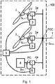
- Figure 1 schematically shows an embodiment of a wind farm according to the invention.
- a first aspect of the invention relates to a control method for a wind farm 100 connected to a power grid 1 and comprising a plurality of generating units 2, such as wind turbines, for example, and a local controller 3 associated to each generating unit 2.
- the wind farm 100 further comprises an associated converter 2a which is associated with each generating unit 2, each local controller 3 acting on its associated converter 2a for controlling the generation of power from the corresponding generating unit 2.
- Figure 1 shows an embodiment of the wind farm 100 further comprising a farm controller 5 acting as the controller of the wind farm 100.
- the farm controller 5 is communicated with the local controllers 3, such that it enables controlling the generation of the generating units 2 through the respective local controllers 3.
- the presence or absence of a voltage disturbance in the grid 1 is determined with the method, and a specific control is performed on the generating units 2 of the wind farm 100 when the presence of a disturbance is determined in order to stabilize the grid 1, keeping the units 2 connected to the grid 1.
- voltage disturbance in the grid 1 must be interpreted as what is commonly known as a low-voltage disturbance or LVRT (Low-voltage Ride Through) or as high-voltage disturbance or HVRT (High-voltage Ride Through).
- the method implements the following measurements in a dynamic and recurrent manner:
- the presence of a disturbance is generally determined when the measured value of at least one of the measured electrical characteristics exceeds a respective associated predetermined maximum threshold value or is below a respective associated predetermined minimum threshold, the absence of a disturbance being determined otherwise.
- controllers 3 can simultaneously determine the presence of a local disturbance, but only controller 5 can determine the presence of a disturbance at the general level of the wind farm.
- a control phase which is executed in a dynamic and recurrent manner, while the presence of the disturbance continues to be determined, is activated.
- the presence or absence of a disturbance continues to be determined in parallel in the way mentioned above, such that when a disturbance disappears it can be determined with the method, and the control phase is deactivated (or stops to be implemented) when said disappearance is determined.
- a stabilization phase which is executed in a continuous and recurrent manner is activated for a limited time interval.
- the farm controller 5 goes from the disturbance state to a stabilization state.
- the generating units 2 of the wind farm 100 are controlled so that they comply with the power requirements required for the wind farm 100 in the presence of a disturbance (for example, the generation of current and/or power to be injected into the grid 1).
- Said control is under the responsibility of the farm controller 5 through the corresponding local controller 3 in each case, or the local controller 3 itself which does not follow the possible instructions that may be received from the farm controller 5, as described in detail below.
- said local controller 3 is said to act independently or in local mode.
- the stabilization phase while the generating units 2 of the wind farm 100 continue to be controlled in order to comply with the power requirements, for the purpose of providing a smooth and controlled transient after the disappearance of disturbance until the voltage of the grid 1 stabilizes in steady-state.
- the wind farm 100 must preferably produce reactive current and/or power for stabilizing the voltage of the grid 1.
- the reactive current and/or power must furthermore be supplied in a dynamic manner according to the measurements taken and to the capacities of the generating units 2.
- the method implements a steady-state phase in which the objective thereof is to comply with the requirements applied to the grid 1 (increasing/decreasing reactive power, following an instruction, etc.), by means of the generating units 2.
- the steady-state phase all the controllers 3 and 5 are in steady-state.
- the farm controller 5 generates generation instructions at all times, regardless of whether or not a disturbance has been determined, and it transmits them to the local controllers 3, as applicable.
- these instructions refer to the power to be generated by the generating units 2, and the local controllers 3 act on the corresponding generating units 2 depending on said received instructions.
- the local controllers 3 may or may not follow these instructions, as described in detail below, but in any case this instruction generation allows the farm controller 5 to take over control of the generating units 2 as soon as possible and in the best way possible when the local mode of the corresponding local controllers 3 ends, moment in which the local controllers 3 act on the respective generating units 2 depending on the received instructions (the farm controller 5 acts as master).
- the local controllers 3 act in local mode, not following the instructions received from the farm controller 5.
- the local controllers 3 act in local mode, and after said time interval has elapsed said local controllers 3 act depending on the instructions they receive from the farm controller 5.
- the transient time interval
- the transient has ended or has stabilized when the following conditions are complied with at the same time (in the moment in which all the conditions are present):
- the actuation of the wind farm 100 as a response to any disturbance is improved when the farm controller 5 controls the local controllers 3, but the transitory response in the event of said disturbance is quicker if the local controllers 3 act in local mode.
- a combination of both advantages is optimally obtained with the second embodiment.
- the dynamic behavior and controllability of the wind farm 100 is thereby improved, which can turn it into the optimum solution for weak grids 1 and for when strict response times are required, for example.
- Each local controller 3 is configured for causing the corresponding generating unit 2 to follow the instructions generated by the farm controller 5, or for said generating unit 2 to act in local mode, as mentioned above.
- a local controller 3 determines the presence of a disturbance and operates in local mode, said local controller 3 activates a reactive power generation mode for the generating unit 2 on which it acts if one of the following conditions is complied with:
- Said local controller 3 activates a reactive current generation mode for said generating unit 2 if said value is outside both ranges, said reactive current generation mode being maintained while said disturbance lasts and said value is maintained outside both ranges.
- Said generating unit 2 thereby generates power according to a local reactive power reference when the local controller 3 is in reactive power generation mode, and generates power according to a local reactive current reference when the local controller 3 is in reactive current generation mode.
- the reference value can be an expected value of said electrical characteristic, or the value of said electrical characteristic measured before determining the presence of a disturbance, for example.
- a local controller 3 When a local controller 3 is in reactive current or power generation mode, it acts on the corresponding generating unit 2 so that said generating unit 2 generates reactive current or power, respectively, depending on said measured value, given that said value gradually changes as the required reactive is being generated (the grid 1 gradually stabilizes), the reactive needs thereby being changed.
- the reactive current and power generated by a generating unit 2 are monitored at all times, and in the moment in which the corresponding local controller 3 determines the presence of a disturbance, the value of the generated reactive current and/or power monitored in that moment is frozen, the corresponding frozen value being able to be used optionally in the reactive current generation mode (in the case of frozen reactive current value) for determining the reactive current to be produced, and in the reactive power generation mode (in the case of frozen reactive power value) for determining the reactive power to be produced.
- a local controller 3 always act in the reactive power generation mode, but in some embodiments, despite complying with the conditions for operating in that mode, in a first moment of the stabilization phase and during a time interval which preferably is less than 100 ms, said controller 3 is caused to act in the reactive current generation mode in order to reduce the electric voltage of the grid 1 (if said voltage exceeds the reference value).
- the wind farm 100 where the method is implemented can further comprise at least one compensation unit 4 with an associated local controller 6 for providing reactive (current and/or power) to the grid 1 when required, as depicted in Figure 1 .
- the local controller 6 is communicated with the farm controller 5.
- a compensation unit 4 can be a STATCOM or a bench of capacitors, for example.
- the local controllers 6 also determine the presence or absence of a disturbance in a manner similar to that of the local controllers 3, and to that end at least one electrical characteristic at a local point of coupling PC associated with each compensation unit 4, preferably the voltage at said point of coupling PC, is measured.
- the operation of a local controller 6 is analogous to that of a local controller 3, so what is described for said local controllers 3 and the different operating possibilities of said local controllers 3 are also applicable to the local controllers 6.
- a second aspect of the invention relates to a wind farm 100 shown by way of example in Figure 1 , which is connected to a grid 1 and comprises a plurality of generating units 2, a local controller 3 associated to each generating unit 2 and a farm controller 5 communicated with all the local controllers 3.
- the wind farm 100 is suitable and configured for supporting and implementing the method of the first aspect of the invention in any of its configurations and/or embodiments. Therefore, in some embodiments said wind farm 100 can further comprise a compensation unit 4 with its associated local controller 6, such as those described above for the first aspect of the invention.
- the farm controller 5 in these cases is communicated with the local controller 6.
- the wind farm 100 further comprises an associated converter 2a which is associated with each generating unit 2, the local controller 3 acting on said converter 2a for controlling the generation of energy from said generating unit 2, and in the corresponding embodiments, it may further comprise an associated converter 4a which is associated to each compensation unit 4, as depicted in Figure 1 , for controlling the generation of said compensation unit 4.
- the wind farm 100 further comprises sensors S PCC and S LV (and S PC , where appropriate) or detectors required for implementing the method, such as for example, those required in order to be able to measure the electrical characteristics based on which the presence or absence of disturbances in the power grid 1 is determined.
- sensors S PCC and S LV (and S PC , where appropriate) are furthermore communicated with the corresponding controllers 3 and 5 (and with the local controllers 6, where appropriate).
Landscapes
- Engineering & Computer Science (AREA)
- Life Sciences & Earth Sciences (AREA)
- Sustainable Development (AREA)
- Sustainable Energy (AREA)
- Chemical & Material Sciences (AREA)
- Combustion & Propulsion (AREA)
- Mechanical Engineering (AREA)
- General Engineering & Computer Science (AREA)
- Power Engineering (AREA)
- Control Of Eletrric Generators (AREA)
- Supply And Distribution Of Alternating Current (AREA)
Claims (11)
- Verfahren zur Steuerung eines Windparks, der an ein Energienetz (1) angeschlossen ist und mehrere Erzeugungseinheiten (2) und eine lokale Steuerung (3), die jeder Erzeugungseinheit (2) zugehörig ist, umfasst, wobei auf dynamische und periodische Weise das Vorhandensein oder Nicht-Vorhandensein einer Spannungsstörung in dem Netz (1) bestimmt wird, wobei eine Steuerungsphase auf dynamische und periodische Weise durchgeführt wird, wenn das Vorhandensein einer Störung bestimmt wird, und die Erzeugungseinheiten (2) während dieses Vorhandenseins gesteuert werden, sodass sie Energie erzeugen und an der Stabilisierung der Spannung in dem Netz (1) während der Steuerungsphase mitwirken, wobei darüber hinaus, wenn das Verschwinden der Störung in dem Verfahren bestimmt wird und bei Nicht-Vorhandensein einer anderen Störung, die Durchführung der Steuerungsphase aufhört und für ein begrenztes Zeitintervall auf dynamische und periodische Weise eine Stabilisierungsphase durchgeführt wird, während die Erzeugungseinheiten (2) während der Stabilisierungsphase weiterhin zum Erzeugen von Energie gesteuert werden, um eine sanfte und gesteuerte Transiente bereitzustellen, bis sich die Spannung des Netzes(1) stabilisiert,
wobei, wenn eine lokale Steuerung (3, 6) das Vorhandensein einer Störung bestimmt, die lokale Steuerung (3, 6) zu Beginn der Steuerungsphase und zu Beginn der Stabilisierungsphase jeweils für ein begrenztes Zeitintervall in einem lokalen Modus arbeitet und dabei auf die ihr zugehörige Einheit (2, 4) einwirkt, ohne den Anweisungen einer Windparksteuerung (5) zu folgen, und dann während der Phasen und nach Ablauf des jeweiligen Zeitintervalls unter Befolgung von Anweisungen der Windparksteuerung (5) auf die ihr zugehörige Einheit (2, 4) einwirkt, wobei, wenn eine lokale Steuerung (3, 6) in dem lokalen Modus agiert, ein reaktiver Energieerzeugungsmodus für die zugehörige Einheit (2, 4) aktiviert wird, wenn der Wert einer gemessenen elektrischen Eigenschaft an einem lokalen Anschlusspunkt (LV), auf dessen Grundlage die entsprechende Störung bestimmt wurde, größer ist als ein spezifischer Referenzwert für die elektrische Eigenschaft und innerhalb eines spezifischen Bereichs von Werten oberhalb des Referenzwertes liegt, oder wenn der Wert geringer ist als der Referenzwert und innerhalb eines spezifischen Bereichs von Werten unterhalb des Referenzwertes liegt, der reaktive Energieerzeugungsmodus beibehalten wird, solange die Störung andauert und der Wert innerhalb eines der Bereiche beibehalten wird, wobei ein reaktiver Stromerzeugungsmodus für die Einheit (2, 4) aktiviert wird, wenn der Wert außerhalb beider Bereiche liegt, und der reaktive Stromerzeugungsmodus beibehalten wird, solange die Störung andauert und der Wert außerhalb beider Bereiche beibehalten wird, wobei die Einheit (2, 4) reaktive Energie gemäß einer lokalen Referenz für reaktive Energie erzeugt, wenn sie sich in dem reaktiven Energieerzeugungsmodus befindet, und reaktiven Strom gemäß einer lokalen Referenz für reaktiven Strom erzeugt, wenn sie sich in dem reaktiven Stromerzeugungsmodus befindet, wobei die reaktive Energie oder der reaktive Strom, die/der von einer Einheit (2, 4) zu produzieren ist, wenn sie sich in dem reaktiven Energieerzeugungsmodus beziehungsweise in dem reaktiven Stromerzeugungsmodus befindet, proportional zu dem gemessenen Wert der elektrischen Eigenschaft an ihrem Anschlusspunkt (LV) ist,
wobei der reaktive Strom und die reaktive Energie, die von jeder Einheit(2, 4) erzeugt werden, jederzeit überwacht werden, wobei die überwachten Werte des produzierten reaktiven Stroms und der produzierten reaktiven Energie eingefroren werden, wenn die entsprechende lokale Steuerung (3, 6) das Vorhandensein einer Störung bestimmt, wobei der eingefrorene Wert des reaktiven Stroms zu dem zu produzierenden reaktiven Strom addiert wird, der proportional zu dem gemessenen Wert der elektrischen Eigenschaft ist, wenn sich die Einheit (2, 4) in dem reaktiven Stromerzeugungsmodus befindet, und der eingefrorene Wert der reaktiven Energie zu der zu produzierenden reaktiven Energie addiert wird, die proportional zu dem gemessenen Wert ist, wenn sich die Einheit (2, 4) in dem reaktiven Energieerzeugungsmodus befindet. - Verfahren zur Steuerung eines Windparks nach Anspruch 1, wobei eine elektrische Eigenschaft des Netzes (1) an dem Verknüpfungspunkt (PCC, Point of Common Coupling) des Windparks (100) und die elektrische Eigenschaft an einem lokalen Anschlusspunkt (LV), der jeder Erzeugungseinheit (2) des Windparks (100) zugehörig ist, auf periodische Weise gemessen werden, wobei die Windparksteuerung (5) das Vorhandensein einer Störung bestimmt, wenn die elektrische Eigenschaft, die an dem Verknüpfungspunkt (PCC) gemessen wird, einen entsprechenden festgelegten maximalen Grenzwert überschreitet oder unter einem entsprechenden festgelegten minimalen Grenzwert liegt oder wenn es eine festgelegte Anzahl lokaler Steuerungen (3) in einem lokalen Störungszustand gibt, und eine lokale Steuerung (3) das Vorhandensein einer lokalen Störung bestimmt und in einen lokalen Störungszustand übergeht, wenn die elektrische Eigenschaft, die an dem entsprechenden Anschlusspunkt (LV) gemessen wird, einen zugehörigen festgelegten maximalen Grenzwert überschreitet oder unter einem zugehörigen festgelegten maximalen Grenzwert liegt.
- Verfahren zur Steuerung eines Windparks nach Anspruch 2, wobei der Windpark (100) ferner mindestens eine Ausgleichseinheit (4) zum Bereitstellen von reaktivem Strom und/oder reaktiver Energie für das Netz (1) bei Bedarf und eine lokale Steuerung (6), die der Ausgleichseinheit (4) zugehörig ist, umfasst, wobei eine elektrische Eigenschaft des Netzes (1) an dem Verknüpfungspunkt (PCC) des Windparks (100), eine elektrische Eigenschaft an einem Anschlusspunkt (LV), der jeder Erzeugungseinheit (2) des Windparks (100) zugehörig ist, und eine elektrische Eigenschaft an dem Anschlusspunkt (PC) des reaktiven Ausgleichers (4) an das Netz (1) auf periodische Weise gemessen werden, wobei die Windparksteuerung (5) das Vorhandensein einer Störung bestimmt, wenn die elektrische Eigenschaft, die an dem Verknüpfungspunkt (PCC) gemessen wird, einen entsprechenden festgelegten maximalen Grenzwert überschreitet oder unter einem entsprechenden festgelegten minimalen Grenzwert liegt oder wenn es eine festgelegte Anzahl lokaler Steuerungen (3, 6) in einem lokalen Störungszustand gibt, und eine lokale Steuerung (3, 6) das Vorhandensein einer lokalen Störung bestimmt und in einen lokalen Störungszustand übergeht, wenn die elektrische Eigenschaft, die an dem entsprechenden Anschlusspunkt (LV, PC) gemessen wird, einen entsprechenden zugehörigen festgelegten maximalen Grenzwert überschreitet oder unter einem entsprechenden zugehörigen festgelegten maximalen Grenzwert liegt.
- Verfahren zur Steuerung eines Windparks nach Anspruch 2 oder 3, wobei, wenn eine lokale Steuerung (3, 6) nicht das Vorhandensein einer Störung bestimmt hat und die Steuerungsphase oder Stabilisierungsphase durchgeführt wird, die lokale Steuerung (3, 6) dazu konfiguriert ist, auf die ihr zugehörige Einheit (2, 4) unter Befolgung von Anweisungen von der Windparksteuerung (5) einzuwirken.
- Verfahren zur Steuerung eines Windparks nach einem der Ansprüche 2 bis 4, wobei, wenn eine lokale Steuerung (3, 6) das Vorhandensein einer Störung bestimmt, die lokale Steuerung (3, 6) dazu konfiguriert ist, während der gesamten Steuerungsphase und der gesamten Stabilisierungsphase auf die ihr zugehörige Einheit (2, 4) unter Befolgung von Anweisungen von der Windparksteuerung (5) einzuwirken.
- Verfahren zur Steuerung eines Windparks nach einem der Ansprüche 1 bis 5, wobei, wenn eine lokale Steuerung (3, 6) dazu konfiguriert ist, im lokalen Modus zu wirken, wenn der gemessene Wert, auf dessen Grundlage das Vorhandensein der entsprechenden Störung bestimmt wurde, außerhalb eines festgelegten Bereichs von Werten liegt, die lokale Steuerung (3, 6) ihre Konfiguration ändert und auf die ihr zugehörige Einheit (2, 4) unter Befolgung der Anweisungen von der Windparksteuerung (5) einwirkt.
- Verfahren zur Steuerung eines Windparks nach einem der Ansprüche 2 bis 6, wobei die gemessene elektrische Eigenschaft die Spannung an dem entsprechenden Anschlusspunkt (PCC, LV, PC) ist.
- Windpark, der mit einem Energienetz (1) verbunden ist und mehrere Erzeugungseinheiten (2) umfasst, ferner eine Windparksteuerung (5) umfassend und für jede Einheit (2) eine zugehörige lokale Steuerung (3) umfassend, wobei der Windpark dazu konfiguriert ist, ein Verfahren nach einem der vorhergehenden Ansprüche auszuführen.
- Windpark nach Anspruch 8, wobei die Windparksteuerung (5) mit allen lokalen Steuerungen (3) in Kommunikationsverbindung steht.
- Windpark nach Anspruch 9, eine Ausgleichseinheit (4) zum Bereitstellen von reaktivem Strom und/oder reaktiver Energie für das Netz (1) bei Bedarf und eine lokale Steuerung (6) für die Ausgleichseinheit (4) umfassend, wobei die Windparksteuerung (5) darüber hinaus mit allen lokalen Steuerungen (3, 6) kommuniziert.
- Windpark nach einem der Ansprüche 8 bis 10, mindestens einen Sensor (SPCC) zum Messen der elektrischen Eigenschaft entsprechend dem Anknüpfungspunkt (PCC) und einen jeweiligen Sensor (SLV, SPC) zum Messen der elektrischen Eigenschaft entsprechend jedem lokalen Anschlusspunkt (LV, PC) umfassend.
Applications Claiming Priority (1)
| Application Number | Priority Date | Filing Date | Title |
|---|---|---|---|
| ES201700563A ES2688089A1 (es) | 2017-04-28 | 2017-04-28 | Método de control para una planta eólica, y planta eólica asociada |
Publications (2)
| Publication Number | Publication Date |
|---|---|
| EP3396156A1 EP3396156A1 (de) | 2018-10-31 |
| EP3396156B1 true EP3396156B1 (de) | 2019-11-27 |
Family
ID=61952503
Family Applications (1)
| Application Number | Title | Priority Date | Filing Date |
|---|---|---|---|
| EP18020138.6A Active EP3396156B1 (de) | 2017-04-28 | 2018-04-06 | Verfahren zur steuerung eines windparks und windpark |
Country Status (6)
| Country | Link |
|---|---|
| US (1) | US20180313327A1 (de) |
| EP (1) | EP3396156B1 (de) |
| CN (1) | CN108808690A (de) |
| BR (1) | BR102018008374A2 (de) |
| ES (2) | ES2688089A1 (de) |
| MX (1) | MX2018005016A (de) |
Families Citing this family (3)
| Publication number | Priority date | Publication date | Assignee | Title |
|---|---|---|---|---|
| CN109449996B (zh) * | 2018-12-29 | 2020-09-22 | 北京金风科创风电设备有限公司 | 变流器的高电压穿越控制方法和装置、存储介质 |
| US20220037014A1 (en) * | 2020-07-28 | 2022-02-03 | Smart Wires Inc. | Prognostics and Diagnostics of Injection Units and Communications |
| CN113595093B (zh) * | 2021-07-19 | 2022-07-22 | 南方电网科学研究院有限责任公司 | 一种新能源电站无功电压自动控制方法、装置及存储介质 |
Family Cites Families (13)
| Publication number | Priority date | Publication date | Assignee | Title |
|---|---|---|---|---|
| CA2697431C (en) * | 2007-12-14 | 2013-09-03 | Shinji Arinaga | Wind power generation system and operation control method thereof |
| US20120104754A1 (en) * | 2009-01-30 | 2012-05-03 | Georg Rudolf | Wind turbine with lvrt capabilities |
| BRPI0917313A2 (pt) * | 2009-02-20 | 2015-11-17 | Mitsubishi Heavy Ind Ltd | gerador de turbina eolica |
| US10103661B2 (en) * | 2011-09-28 | 2018-10-16 | Vestas Wind Systems A/S | Wind power plant and a method for operating thereof |
| US9631608B2 (en) * | 2012-06-12 | 2017-04-25 | Vestas Wind Systems A/S | Wind-power-plant control upon low-voltage grid faults |
| EP2891217A4 (de) * | 2012-08-30 | 2016-05-25 | Gen Electric | System und verfahren zum schutz elektrischer maschinen |
| EP2741392A3 (de) * | 2012-12-04 | 2016-12-14 | ABB Research Ltd. | Systeme und Verfahren zur Verwendung eines aktiven Kompensators zur Verstärkung eines Diodengleichrichters |
| WO2014090255A1 (en) * | 2012-12-14 | 2014-06-19 | Vestas Wind Systems A/S | Method and arrangement for swift power regulation |
| EP2957012B1 (de) * | 2013-02-15 | 2017-05-03 | Vestas Wind Systems A/S | Verfahren für den betrieb einer windkraftanlage |
| EP3061170B1 (de) * | 2013-10-21 | 2020-09-16 | Vestas Wind Systems A/S | Verfahren zur regelung einer windenergieanlage und windenergieanlage |
| CN105794068B (zh) | 2013-11-28 | 2019-09-13 | 维斯塔斯风力系统集团公司 | 风力发电厂中无功功率的控制 |
| US10116138B2 (en) | 2013-12-11 | 2018-10-30 | Vestas Wind Systems A/S | Wind power plant, and a method for controlling a reactive current injection in a wind power plant |
| CN107078511B (zh) * | 2014-11-03 | 2019-11-08 | 维斯塔斯风力系统集团公司 | 控制风力发电厂的有功功率生成和风力发电厂的方法 |
-
2017
- 2017-04-28 ES ES201700563A patent/ES2688089A1/es not_active Withdrawn
-
2018
- 2018-04-06 ES ES18020138T patent/ES2760748T3/es active Active
- 2018-04-06 EP EP18020138.6A patent/EP3396156B1/de active Active
- 2018-04-24 MX MX2018005016A patent/MX2018005016A/es unknown
- 2018-04-25 CN CN201810382098.XA patent/CN108808690A/zh active Pending
- 2018-04-25 BR BR102018008374-0A patent/BR102018008374A2/pt not_active IP Right Cessation
- 2018-04-26 US US15/963,490 patent/US20180313327A1/en not_active Abandoned
Non-Patent Citations (1)
| Title |
|---|
| None * |
Also Published As
| Publication number | Publication date |
|---|---|
| MX2018005016A (es) | 2018-12-17 |
| EP3396156A1 (de) | 2018-10-31 |
| CN108808690A (zh) | 2018-11-13 |
| US20180313327A1 (en) | 2018-11-01 |
| ES2688089A1 (es) | 2018-10-30 |
| ES2760748T3 (es) | 2020-05-14 |
| BR102018008374A2 (pt) | 2019-03-12 |
Similar Documents
| Publication | Publication Date | Title |
|---|---|---|
| US9997922B2 (en) | Method for feeding electrical power into an electrical supply network | |
| KR101890465B1 (ko) | 전기 발전 장치를 제어하기 위한 방법 | |
| CA2934348C (en) | Method and regulation and/or control device for operating a wind turbine and/or a wind farm, and wind turbine and wind farm | |
| DK2594005T3 (en) | Control unit for damping power oscillation | |
| CN108695897B (zh) | 光伏电站的功率控制方法、装置、控制器、系统及介质 | |
| EP2859638B1 (de) | Steuerung einer windkraftanlage nach niederspannungsnetzdefekten | |
| RU2653616C2 (ru) | Способ управления ветровым парком | |
| DK2659138T3 (en) | WINDOW PARK AND PROCEDURE FOR OPERATING A WINDOW | |
| US11088546B2 (en) | Method and wind turbine for feeding electric power | |
| EP2932093B1 (de) | Verfahren und anordnung zur schnellen leistungsregelung | |
| KR20120024528A (ko) | 풍력 발전 장치의 제어 장치 및 제어 방법 | |
| CN111699602A (zh) | 用于将电功率馈入到供电网中的方法 | |
| KR20190064645A (ko) | 풍력 발전 설비를 작동하기 위한 방법 | |
| KR101605681B1 (ko) | 화력 발전소의 작동 방법 | |
| EP3396156A1 (de) | Verfahren zur steuerung eines windparks und windpark | |
| US8861239B2 (en) | Regulating output characteristics of static energy supply units | |
| US20190273379A1 (en) | A method of providing power support to an electrical power grid | |
| WO2012159678A1 (en) | Power system | |
| US10505372B2 (en) | Method for supplying electrical power | |
| EP2793343A1 (de) | Koordination von Spannungssteuervorrichtungen in einem Windpark, die mit einem Einversorgungsnetz aus mehreren Windturbinen verbunden sind | |
| EP2346133B1 (de) | Wandlervorrichtung und Verfahren zum Umwandeln von Strom | |
| EP4525253A1 (de) | Steuerungssystem zur bereitstellung von regeldifferenzsteuerung und windturbine | |
| EP3211223A1 (de) | Windkraftsystem und verfahren zur steuerung des windkraftsystems | |
| EP2346135B1 (de) | Wandlervorrichtung und Verfahren zum Umwandeln von Strom |
Legal Events
| Date | Code | Title | Description |
|---|---|---|---|
| PUAI | Public reference made under article 153(3) epc to a published international application that has entered the european phase |
Free format text: ORIGINAL CODE: 0009012 |
|
| STAA | Information on the status of an ep patent application or granted ep patent |
Free format text: STATUS: THE APPLICATION HAS BEEN PUBLISHED |
|
| AK | Designated contracting states |
Kind code of ref document: A1 Designated state(s): AL AT BE BG CH CY CZ DE DK EE ES FI FR GB GR HR HU IE IS IT LI LT LU LV MC MK MT NL NO PL PT RO RS SE SI SK SM TR |
|
| AX | Request for extension of the european patent |
Extension state: BA ME |
|
| STAA | Information on the status of an ep patent application or granted ep patent |
Free format text: STATUS: REQUEST FOR EXAMINATION WAS MADE |
|
| 17P | Request for examination filed |
Effective date: 20181019 |
|
| RBV | Designated contracting states (corrected) |
Designated state(s): AL AT BE BG CH CY CZ DE DK EE ES FI FR GB GR HR HU IE IS IT LI LT LU LV MC MK MT NL NO PL PT RO RS SE SI SK SM TR |
|
| RAP1 | Party data changed (applicant data changed or rights of an application transferred) |
Owner name: SIEMENS GAMESA RENEWABLE ENERGY INNOVATION & TECHN |
|
| GRAP | Despatch of communication of intention to grant a patent |
Free format text: ORIGINAL CODE: EPIDOSNIGR1 |
|
| STAA | Information on the status of an ep patent application or granted ep patent |
Free format text: STATUS: GRANT OF PATENT IS INTENDED |
|
| RIC1 | Information provided on ipc code assigned before grant |
Ipc: H02J 3/38 20060101ALI20190603BHEP Ipc: H02J 3/46 20060101ALI20190603BHEP Ipc: F03D 7/04 20060101ALI20190603BHEP Ipc: H02J 3/18 20060101ALI20190603BHEP Ipc: F03D 7/02 20060101AFI20190603BHEP |
|
| INTG | Intention to grant announced |
Effective date: 20190625 |
|
| GRAS | Grant fee paid |
Free format text: ORIGINAL CODE: EPIDOSNIGR3 |
|
| GRAA | (expected) grant |
Free format text: ORIGINAL CODE: 0009210 |
|
| STAA | Information on the status of an ep patent application or granted ep patent |
Free format text: STATUS: THE PATENT HAS BEEN GRANTED |
|
| AK | Designated contracting states |
Kind code of ref document: B1 Designated state(s): AL AT BE BG CH CY CZ DE DK EE ES FI FR GB GR HR HU IE IS IT LI LT LU LV MC MK MT NL NO PL PT RO RS SE SI SK SM TR |
|
| REG | Reference to a national code |
Ref country code: GB Ref legal event code: FG4D |
|
| REG | Reference to a national code |
Ref country code: CH Ref legal event code: EP |
|
| REG | Reference to a national code |
Ref country code: DE Ref legal event code: R096 Ref document number: 602018001301 Country of ref document: DE |
|
| REG | Reference to a national code |
Ref country code: AT Ref legal event code: REF Ref document number: 1206938 Country of ref document: AT Kind code of ref document: T Effective date: 20191215 |
|
| REG | Reference to a national code |
Ref country code: IE Ref legal event code: FG4D |
|
| REG | Reference to a national code |
Ref country code: NL Ref legal event code: MP Effective date: 20191127 |
|
| REG | Reference to a national code |
Ref country code: LT Ref legal event code: MG4D |
|
| PG25 | Lapsed in a contracting state [announced via postgrant information from national office to epo] |
Ref country code: NL Free format text: LAPSE BECAUSE OF FAILURE TO SUBMIT A TRANSLATION OF THE DESCRIPTION OR TO PAY THE FEE WITHIN THE PRESCRIBED TIME-LIMIT Effective date: 20191127 Ref country code: LT Free format text: LAPSE BECAUSE OF FAILURE TO SUBMIT A TRANSLATION OF THE DESCRIPTION OR TO PAY THE FEE WITHIN THE PRESCRIBED TIME-LIMIT Effective date: 20191127 Ref country code: GR Free format text: LAPSE BECAUSE OF FAILURE TO SUBMIT A TRANSLATION OF THE DESCRIPTION OR TO PAY THE FEE WITHIN THE PRESCRIBED TIME-LIMIT Effective date: 20200228 Ref country code: BG Free format text: LAPSE BECAUSE OF FAILURE TO SUBMIT A TRANSLATION OF THE DESCRIPTION OR TO PAY THE FEE WITHIN THE PRESCRIBED TIME-LIMIT Effective date: 20200227 Ref country code: FI Free format text: LAPSE BECAUSE OF FAILURE TO SUBMIT A TRANSLATION OF THE DESCRIPTION OR TO PAY THE FEE WITHIN THE PRESCRIBED TIME-LIMIT Effective date: 20191127 Ref country code: NO Free format text: LAPSE BECAUSE OF FAILURE TO SUBMIT A TRANSLATION OF THE DESCRIPTION OR TO PAY THE FEE WITHIN THE PRESCRIBED TIME-LIMIT Effective date: 20200227 Ref country code: SE Free format text: LAPSE BECAUSE OF FAILURE TO SUBMIT A TRANSLATION OF THE DESCRIPTION OR TO PAY THE FEE WITHIN THE PRESCRIBED TIME-LIMIT Effective date: 20191127 Ref country code: LV Free format text: LAPSE BECAUSE OF FAILURE TO SUBMIT A TRANSLATION OF THE DESCRIPTION OR TO PAY THE FEE WITHIN THE PRESCRIBED TIME-LIMIT Effective date: 20191127 |
|
| REG | Reference to a national code |
Ref country code: ES Ref legal event code: FG2A Ref document number: 2760748 Country of ref document: ES Kind code of ref document: T3 Effective date: 20200514 |
|
| PG25 | Lapsed in a contracting state [announced via postgrant information from national office to epo] |
Ref country code: HR Free format text: LAPSE BECAUSE OF FAILURE TO SUBMIT A TRANSLATION OF THE DESCRIPTION OR TO PAY THE FEE WITHIN THE PRESCRIBED TIME-LIMIT Effective date: 20191127 Ref country code: IS Free format text: LAPSE BECAUSE OF FAILURE TO SUBMIT A TRANSLATION OF THE DESCRIPTION OR TO PAY THE FEE WITHIN THE PRESCRIBED TIME-LIMIT Effective date: 20200327 Ref country code: RS Free format text: LAPSE BECAUSE OF FAILURE TO SUBMIT A TRANSLATION OF THE DESCRIPTION OR TO PAY THE FEE WITHIN THE PRESCRIBED TIME-LIMIT Effective date: 20191127 |
|
| PG25 | Lapsed in a contracting state [announced via postgrant information from national office to epo] |
Ref country code: AL Free format text: LAPSE BECAUSE OF FAILURE TO SUBMIT A TRANSLATION OF THE DESCRIPTION OR TO PAY THE FEE WITHIN THE PRESCRIBED TIME-LIMIT Effective date: 20191127 |
|
| PG25 | Lapsed in a contracting state [announced via postgrant information from national office to epo] |
Ref country code: CZ Free format text: LAPSE BECAUSE OF FAILURE TO SUBMIT A TRANSLATION OF THE DESCRIPTION OR TO PAY THE FEE WITHIN THE PRESCRIBED TIME-LIMIT Effective date: 20191127 Ref country code: DK Free format text: LAPSE BECAUSE OF FAILURE TO SUBMIT A TRANSLATION OF THE DESCRIPTION OR TO PAY THE FEE WITHIN THE PRESCRIBED TIME-LIMIT Effective date: 20191127 Ref country code: RO Free format text: LAPSE BECAUSE OF FAILURE TO SUBMIT A TRANSLATION OF THE DESCRIPTION OR TO PAY THE FEE WITHIN THE PRESCRIBED TIME-LIMIT Effective date: 20191127 Ref country code: PT Free format text: LAPSE BECAUSE OF FAILURE TO SUBMIT A TRANSLATION OF THE DESCRIPTION OR TO PAY THE FEE WITHIN THE PRESCRIBED TIME-LIMIT Effective date: 20200419 Ref country code: EE Free format text: LAPSE BECAUSE OF FAILURE TO SUBMIT A TRANSLATION OF THE DESCRIPTION OR TO PAY THE FEE WITHIN THE PRESCRIBED TIME-LIMIT Effective date: 20191127 |
|
| REG | Reference to a national code |
Ref country code: DE Ref legal event code: R097 Ref document number: 602018001301 Country of ref document: DE |
|
| PG25 | Lapsed in a contracting state [announced via postgrant information from national office to epo] |
Ref country code: SK Free format text: LAPSE BECAUSE OF FAILURE TO SUBMIT A TRANSLATION OF THE DESCRIPTION OR TO PAY THE FEE WITHIN THE PRESCRIBED TIME-LIMIT Effective date: 20191127 Ref country code: SM Free format text: LAPSE BECAUSE OF FAILURE TO SUBMIT A TRANSLATION OF THE DESCRIPTION OR TO PAY THE FEE WITHIN THE PRESCRIBED TIME-LIMIT Effective date: 20191127 |
|
| REG | Reference to a national code |
Ref country code: AT Ref legal event code: MK05 Ref document number: 1206938 Country of ref document: AT Kind code of ref document: T Effective date: 20191127 |
|
| PLBE | No opposition filed within time limit |
Free format text: ORIGINAL CODE: 0009261 |
|
| STAA | Information on the status of an ep patent application or granted ep patent |
Free format text: STATUS: NO OPPOSITION FILED WITHIN TIME LIMIT |
|
| 26N | No opposition filed |
Effective date: 20200828 |
|
| PG25 | Lapsed in a contracting state [announced via postgrant information from national office to epo] |
Ref country code: MC Free format text: LAPSE BECAUSE OF FAILURE TO SUBMIT A TRANSLATION OF THE DESCRIPTION OR TO PAY THE FEE WITHIN THE PRESCRIBED TIME-LIMIT Effective date: 20191127 Ref country code: SI Free format text: LAPSE BECAUSE OF FAILURE TO SUBMIT A TRANSLATION OF THE DESCRIPTION OR TO PAY THE FEE WITHIN THE PRESCRIBED TIME-LIMIT Effective date: 20191127 Ref country code: PL Free format text: LAPSE BECAUSE OF FAILURE TO SUBMIT A TRANSLATION OF THE DESCRIPTION OR TO PAY THE FEE WITHIN THE PRESCRIBED TIME-LIMIT Effective date: 20191127 Ref country code: AT Free format text: LAPSE BECAUSE OF FAILURE TO SUBMIT A TRANSLATION OF THE DESCRIPTION OR TO PAY THE FEE WITHIN THE PRESCRIBED TIME-LIMIT Effective date: 20191127 |
|
| PG25 | Lapsed in a contracting state [announced via postgrant information from national office to epo] |
Ref country code: FR Free format text: LAPSE BECAUSE OF NON-PAYMENT OF DUE FEES Effective date: 20200430 Ref country code: IT Free format text: LAPSE BECAUSE OF FAILURE TO SUBMIT A TRANSLATION OF THE DESCRIPTION OR TO PAY THE FEE WITHIN THE PRESCRIBED TIME-LIMIT Effective date: 20191127 Ref country code: LU Free format text: LAPSE BECAUSE OF NON-PAYMENT OF DUE FEES Effective date: 20200406 |
|
| REG | Reference to a national code |
Ref country code: BE Ref legal event code: MM Effective date: 20200430 |
|
| PG25 | Lapsed in a contracting state [announced via postgrant information from national office to epo] |
Ref country code: BE Free format text: LAPSE BECAUSE OF NON-PAYMENT OF DUE FEES Effective date: 20200430 |
|
| PG25 | Lapsed in a contracting state [announced via postgrant information from national office to epo] |
Ref country code: IE Free format text: LAPSE BECAUSE OF NON-PAYMENT OF DUE FEES Effective date: 20200406 |
|
| PG25 | Lapsed in a contracting state [announced via postgrant information from national office to epo] |
Ref country code: CH Free format text: LAPSE BECAUSE OF NON-PAYMENT OF DUE FEES Effective date: 20210430 Ref country code: LI Free format text: LAPSE BECAUSE OF NON-PAYMENT OF DUE FEES Effective date: 20210430 |
|
| PG25 | Lapsed in a contracting state [announced via postgrant information from national office to epo] |
Ref country code: TR Free format text: LAPSE BECAUSE OF FAILURE TO SUBMIT A TRANSLATION OF THE DESCRIPTION OR TO PAY THE FEE WITHIN THE PRESCRIBED TIME-LIMIT Effective date: 20191127 Ref country code: MT Free format text: LAPSE BECAUSE OF FAILURE TO SUBMIT A TRANSLATION OF THE DESCRIPTION OR TO PAY THE FEE WITHIN THE PRESCRIBED TIME-LIMIT Effective date: 20191127 Ref country code: CY Free format text: LAPSE BECAUSE OF FAILURE TO SUBMIT A TRANSLATION OF THE DESCRIPTION OR TO PAY THE FEE WITHIN THE PRESCRIBED TIME-LIMIT Effective date: 20191127 |
|
| PG25 | Lapsed in a contracting state [announced via postgrant information from national office to epo] |
Ref country code: MK Free format text: LAPSE BECAUSE OF FAILURE TO SUBMIT A TRANSLATION OF THE DESCRIPTION OR TO PAY THE FEE WITHIN THE PRESCRIBED TIME-LIMIT Effective date: 20191127 |
|
| REG | Reference to a national code |
Ref country code: DE Ref legal event code: R082 Ref document number: 602018001301 Country of ref document: DE Representative=s name: SAUTHOFF, KARSTEN, DIPL.-ING. UNIV., DE |
|
| PGFP | Annual fee paid to national office [announced via postgrant information from national office to epo] |
Ref country code: DE Payment date: 20250428 Year of fee payment: 8 |
|
| PGFP | Annual fee paid to national office [announced via postgrant information from national office to epo] |
Ref country code: ES Payment date: 20250513 Year of fee payment: 8 |
|
| PGFP | Annual fee paid to national office [announced via postgrant information from national office to epo] |
Ref country code: GB Payment date: 20260323 Year of fee payment: 9 |