EP3396103B1 - Block manifold - Google Patents
Block manifold Download PDFInfo
- Publication number
- EP3396103B1 EP3396103B1 EP16834079.2A EP16834079A EP3396103B1 EP 3396103 B1 EP3396103 B1 EP 3396103B1 EP 16834079 A EP16834079 A EP 16834079A EP 3396103 B1 EP3396103 B1 EP 3396103B1
- Authority
- EP
- European Patent Office
- Prior art keywords
- equipment
- subsea
- manifold
- machined
- wells
- Prior art date
- Legal status (The legal status is an assumption and is not a legal conclusion. Google has not performed a legal analysis and makes no representation as to the accuracy of the status listed.)
- Active
Links
Images


Classifications
-
- E—FIXED CONSTRUCTIONS
- E21—EARTH OR ROCK DRILLING; MINING
- E21B—EARTH OR ROCK DRILLING; OBTAINING OIL, GAS, WATER, SOLUBLE OR MELTABLE MATERIALS OR A SLURRY OF MINERALS FROM WELLS
- E21B43/00—Methods or apparatus for obtaining oil, gas, water, soluble or meltable materials or a slurry of minerals from wells
- E21B43/01—Methods or apparatus for obtaining oil, gas, water, soluble or meltable materials or a slurry of minerals from wells specially adapted for obtaining from underwater installations
-
- E—FIXED CONSTRUCTIONS
- E21—EARTH OR ROCK DRILLING; MINING
- E21B—EARTH OR ROCK DRILLING; OBTAINING OIL, GAS, WATER, SOLUBLE OR MELTABLE MATERIALS OR A SLURRY OF MINERALS FROM WELLS
- E21B43/00—Methods or apparatus for obtaining oil, gas, water, soluble or meltable materials or a slurry of minerals from wells
- E21B43/01—Methods or apparatus for obtaining oil, gas, water, soluble or meltable materials or a slurry of minerals from wells specially adapted for obtaining from underwater installations
- E21B43/017—Production satellite stations, i.e. underwater installations comprising a plurality of satellite well heads connected to a central station
- E21B43/0175—Hydraulic schemes for production manifolds
-
- E—FIXED CONSTRUCTIONS
- E21—EARTH OR ROCK DRILLING; MINING
- E21B—EARTH OR ROCK DRILLING; OBTAINING OIL, GAS, WATER, SOLUBLE OR MELTABLE MATERIALS OR A SLURRY OF MINERALS FROM WELLS
- E21B17/00—Drilling rods or pipes; Flexible drill strings; Kellies; Drill collars; Sucker rods; Cables; Casings; Tubings
- E21B17/02—Couplings; joints
-
- E—FIXED CONSTRUCTIONS
- E21—EARTH OR ROCK DRILLING; MINING
- E21B—EARTH OR ROCK DRILLING; OBTAINING OIL, GAS, WATER, SOLUBLE OR MELTABLE MATERIALS OR A SLURRY OF MINERALS FROM WELLS
- E21B34/00—Valve arrangements for boreholes or wells
-
- E—FIXED CONSTRUCTIONS
- E21—EARTH OR ROCK DRILLING; MINING
- E21B—EARTH OR ROCK DRILLING; OBTAINING OIL, GAS, WATER, SOLUBLE OR MELTABLE MATERIALS OR A SLURRY OF MINERALS FROM WELLS
- E21B41/00—Equipment or details not covered by groups E21B15/00 - E21B40/00
- E21B41/0007—Equipment or details not covered by groups E21B15/00 - E21B40/00 for underwater installations
-
- E—FIXED CONSTRUCTIONS
- E21—EARTH OR ROCK DRILLING; MINING
- E21B—EARTH OR ROCK DRILLING; OBTAINING OIL, GAS, WATER, SOLUBLE OR MELTABLE MATERIALS OR A SLURRY OF MINERALS FROM WELLS
- E21B43/00—Methods or apparatus for obtaining oil, gas, water, soluble or meltable materials or a slurry of minerals from wells
- E21B43/01—Methods or apparatus for obtaining oil, gas, water, soluble or meltable materials or a slurry of minerals from wells specially adapted for obtaining from underwater installations
- E21B43/0107—Connecting of flow lines to offshore structures
-
- E—FIXED CONSTRUCTIONS
- E21—EARTH OR ROCK DRILLING; MINING
- E21B—EARTH OR ROCK DRILLING; OBTAINING OIL, GAS, WATER, SOLUBLE OR MELTABLE MATERIALS OR A SLURRY OF MINERALS FROM WELLS
- E21B43/00—Methods or apparatus for obtaining oil, gas, water, soluble or meltable materials or a slurry of minerals from wells
- E21B43/01—Methods or apparatus for obtaining oil, gas, water, soluble or meltable materials or a slurry of minerals from wells specially adapted for obtaining from underwater installations
- E21B43/013—Connecting a production flow line to an underwater well head
-
- F—MECHANICAL ENGINEERING; LIGHTING; HEATING; WEAPONS; BLASTING
- F16—ENGINEERING ELEMENTS AND UNITS; GENERAL MEASURES FOR PRODUCING AND MAINTAINING EFFECTIVE FUNCTIONING OF MACHINES OR INSTALLATIONS; THERMAL INSULATION IN GENERAL
- F16L—PIPES; JOINTS OR FITTINGS FOR PIPES; SUPPORTS FOR PIPES, CABLES OR PROTECTIVE TUBING; MEANS FOR THERMAL INSULATION IN GENERAL
- F16L1/00—Laying or reclaiming pipes; Repairing or joining pipes on or under water
- F16L1/26—Repairing or joining pipes on or under water
Definitions
- the present invention relates to equipment for connection of pipelines forming subsea lines of connection between two or more equipment, with an oil production platform in open sea, or directly to the offshore. Said pipelines are used for fluid of flow from production, or further destined to the injection or service on oil wells.
- the present invention is also related of a drilling system in a subsea oil field.
- connection systems for subsea pipelines have major importance in the oil industry, especially at offshore areas. Necessity to transport fluids in great depths connecting oil wells to the platforms, two or more subsea equipment or transport directly to the offshore, for example, requires kilometers of pipelines of fluid transport and, subsequently, of equipment connecting said pipelines.
- connection equipment are assembled at intermediate points or at the end of pipelines and are typically composed of a metal frame for foundation on sea soil, control and fluid block valves, sections of intermediate pipelines and spindles for connection with other equipment, for fluid import and export, as well as injection or service on the well.
- a further frame is required, partially independent of foundation frame, which has the function of fix these components and to withstand the stresses generated by the weight of line during installation, keeping the components pressurized which have contact with the production or injection fluid out of load line during installation.
- subsea equipment typically have a very robust structure, i.e., high dimensions and weight to withstand underwater conditions, where pressure and corrosion resistance requirements are severe, as well as extreme loads occurring during installation of the same.
- PLET or PLEM Peline End Manifold
- the integration of these components requires critical weld strands, that is, complex processes since welding requires both special preparation and qualification, which are costly and time consuming processes.
- the integration process requires at least four months for the manufacturing and delivery process of PLET-type equipment.
Landscapes
- Engineering & Computer Science (AREA)
- Geology (AREA)
- Life Sciences & Earth Sciences (AREA)
- Mining & Mineral Resources (AREA)
- Environmental & Geological Engineering (AREA)
- Fluid Mechanics (AREA)
- Physics & Mathematics (AREA)
- General Life Sciences & Earth Sciences (AREA)
- Geochemistry & Mineralogy (AREA)
- Mechanical Engineering (AREA)
- General Engineering & Computer Science (AREA)
- Earth Drilling (AREA)
- Pipeline Systems (AREA)
Description
- The present invention relates to equipment for connection of pipelines forming subsea lines of connection between two or more equipment, with an oil production platform in open sea, or directly to the offshore. Said pipelines are used for fluid of flow from production, or further destined to the injection or service on oil wells. The present invention is also related of a drilling system in a subsea oil field.
- Connection systems for subsea pipelines have major importance in the oil industry, especially at offshore areas. Necessity to transport fluids in great depths connecting oil wells to the platforms, two or more subsea equipment or transport directly to the offshore, for example, requires kilometers of pipelines of fluid transport and, subsequently, of equipment connecting said pipelines.
- The connection equipment (or termination) are assembled at intermediate points or at the end of pipelines and are typically composed of a metal frame for foundation on sea soil, control and fluid block valves, sections of intermediate pipelines and spindles for connection with other equipment, for fluid import and export, as well as injection or service on the well. In addition, a further frame is required, partially independent of foundation frame, which has the function of fix these components and to withstand the stresses generated by the weight of line during installation, keeping the components pressurized which have contact with the production or injection fluid out of load line during installation.
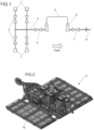
- An example of typical subsea architecture diagram for connection between manifold for four wells and Pipeline End Termination (PLET) is shown on
Figure 1 (state of the art). This diagram illustrates a production manifold which is used to collect fluids from the wells, exporting them to line connection equipment, such as a PLET by means of a jumper or spool. - A typical schematic view of a state of the art manifold, spool or jumper, and PLET is the shown in
Figure 1 . The manifold comprising fluid import/export mandrels (1) is connect to the header (3) by means of block valve (2) to each Wet Christmas Tree (WCT) branch and an additional valve for the header (4). This header (4) of the manifold, by a mandrel, is connected to a jumper or spool (5) - rigid and flexible pipelines containing a vertical or horizontal crimp at each of its ends - by subsea connectors (6), which need to be locked or unlocked with the use of remotely operated subsea vehicles and still making the seal between equipment to avoid leaks. The jumper or spool (5), in turn, is connected to the PLET mandrel, which has a block valve (7) to performing subsea line isolation (8) welded to the PLET. All these equipment have to be assembled on a frame (9) resistant enough to withstand all stresses from the lines, as indicated inFigure 2. Figures 2 and3 illustrate perspective and front cut views, respectively, the frame (9) of a typical PLET and detail of line supporting beam (10), as usually practice by the state of the art. - The architecture illustrated in
Figure 1 then essentially needs a manifold, jumper or spool, PLET, six stop valves, which can vary as the manifold application or field need, and additionally two more connectors. It occurs that in operational practice, said state of the art architecture presents two potential points of undesirable fluid leak, which are the said connectors. - In addition, it is still necessary a plurality of other components, besides essentials, such as welding seams, secondary valves and components for seal that require a structural stress to withstand them. Other important factor is the particularity of subsea environment, whose increasing depth exert great pressure on the lines, making them increasingly heavy and demanding more of the equipment installed.
-
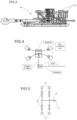
Figure 4 shows a typical four wells system, where a manifold is interconnected to four Wet Christmas Trees (WCT), a jumper or spool connected to conventional PLET equipment. The production trees are linked to the manifold, the latter of which is intended to equalize the production from the wells. PLET is used to interconnect the manifold with the production lines. At the conventional frame of manifold and installation methods of conventional subsea equipment, it is not possible to realize a direct interconnection of line with said manifold. Thus, PLET is necessary to perform the descent of production line, usually measuring kilometers and weighting on order of more than 600 tons, responsible for outflow of production and in order to be possible to make interconnection with manifold. In other words, at the traditional methods there is no possibility to make the direct connection of these production lines with manifold, thus needing PLET. - The document
US4874008A , which discloses a connection equipment having the features of the pre-characterizing portion ofclaim 1, reveals a valve mounting between spaced apart flat surfaces wherein the valve may be removed and replaced in environments such as subsea locations. The document also reveals the application of a plurality of valve modules connected to the exterior at a block manifold body through the use of hydraulic studs. - Furthermore, in traditional oil drilling systems, a plurality of other components, other than the above-mentioned essentials, such as weld beads, secondary valves, and seal components are required which require significant structural effort to support them. Another important factor is the particularity of the subsea environment, whose depth, increasing, exerts great pressure on the lines making them increasingly heavy and demanding more of the equipment installed.
- As is known, subsea equipment typically have a very robust structure, i.e., high dimensions and weight to withstand underwater conditions, where pressure and corrosion resistance requirements are severe, as well as extreme loads occurring during installation of the same. When manufacturing a PLET or PLEM (Pipeline End Manifold) type of equipment, it is first necessary to develop the project design and then proceed with the manufacture of pressurized elements such as valves, pipes and ducts. Once these elements are manufactured, they must be integrated with the metallic interface structure with sea soil, such as foundation, balconies or mudmat, as well as with the supporting metal beams for these components necessary for the installation of the equipment in the soil subsea. The integration of these components requires critical weld strands, that is, complex processes since welding requires both special preparation and qualification, which are costly and time consuming processes. Currently, the integration process requires at least four months for the manufacturing and delivery process of PLET-type equipment.
- PLET-type equipment is then connected to a flexible or rigid pipe through which the oil/gas production flows or the water/gas is injected into the WCTs installed in the wells. This tube in an subsea field extends for kilometers of distances, for example, 10 km, representing a typical weight of about 600 tons. When installing PLET-type equipment, this pipe will be connected to the equipment, as shown in
Figure 3 . However, it is required that the load line from the loads carried by that tube does not pass through the pressurized elements, such as valves, pipes and ducts and, in order to comply with this requirement, a structural support beam (10) of the line to support this weight, thereby protecting said pressurized elements which are in contact with the production or injection fluid. Said structural framework is shown inFigures 2 and3 . - The support structure, including said supporting beam of the line (10), adds to the equipment a very high dimension and weight requiring special vessels for its installation. As the PLET design is not standardized and has support structures that change as needed, special vessels and support logistics for the installation are changed on a case-by-case basis, making the subsea field projects more expensive and increasing the actual time of its installation.
- All of these factors contribute significantly to delaying the subsea production process, increasing costs related to design, fabrication, testing, transportation, mechanical integration, and installation of equipment in the seabed.
- Currently there are in the market efforts and technological developments in an attempt to reduce the costs of the equipment for production and oil drilling. In this sense, an effort has been made in researches and solutions carried out in the equipment itself as well as solutions that make feasible the optimization of the configuration of the subsea field, but to date there is no adequate solution for this technological demand.
- The present invention advantageously, robustly and efficiently solves all of the above-mentioned drawbacks of the prior art, in addition to others arising and not mentioned herein.
- Thus, the objective of the present invention is to provide a new equipment for connection of pipelines directed to subsea applications that also represents an optimization of the oil drilling field system.
- As will be appreciated, the equipment for connection of ducts object of the present invention has a simplified configuration allowing the connection of the duct directly to the valve block and no longer requiring special structural framing to protect the pressurized elements which are in contact with the production fluid or injection. Its lifting, as well as the load line during installation/operation, will take place through fixed or articulated eyebolts integral to the valve block.
- The equipment for connection of subsea pipelines in block architecture according to the present invention has the features of
claim 1. - Since the block architecture described herein is capable of withstanding loading and installation/operating pressures, the need for a metal structure to support and sustain the load (or stresses) suffered by the equipment exerted by the pipe will, therefore, eliminated, leaving the equipment lighter, more robust and more effective.
- In addition, the block architecture allows the coexistence of two equipment in only one, in other words, PLET has absorbed the possibility of interconnecting the wells and receiving the necessary stop valves. Still, the new equipment becomes feasible because block manufacture, in addition to greatly reducing the size of the manifold, does not require the metallic support structure for the installation loads and for the pressurized elements.
- Preferably, the block manifold used in the equipment of the present invention has structure and operation according to that object of the international patent application
WO 2016/044910 A1 . - The equipment for connection of subsea pipelines in block architecture according to the present invention may be well understood with the description of the other attached schematic figures, which in a non-limiting or restrictive way of the structure developed, illustrate:
-
Figure 5 - schematic diagram of architecture for connection of lines or subsea pipelines. -
Figure 6 - perspective view of the equipment for connection of lines or subsea pipelines object of the present invention. -
Figure 7 is a perspective view of the equipment for connection of lines or subsea pipelines shown inFigure 6 , showing the manifold in block. -
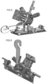
Figure 8 - perspective view of the equipment for connection of lines or subsea pipelines object of the present invention in installation of the first end where it is suspended by the subsea line or pipeline. -
Figure 9 - perspective view of the equipment for connection of lines or subsea pipelines object of the present invention in installation of the second end where the equipment is suspended by the eyebolt. -
Figure 10 - Schematic diagram of the oil drilling system according to the invention for four wells. - Essentially, in
Figure 5 is illustrated the simplified schematic architecture diagram of the equipment for connection of subsea pipelines in block architecture according to the present invention, for use in four wells. It will be noted, then, that the equipment has been significantly simplified to only include connection between fluid import mandrel (11) and subsea line or duct (14), assembled in the manifold block (13) which is provided with stop valves (12). As can further be seen, the flow of the fluid to be transported will occur in the sense (11)-(12)-(13)-(14), - the reverse flow being used in applications for injection or service systems. It is noteworthy that the stop valves (12) are located inside the block (13) and thus protected. - With such equipment configuration according to the present invention, the subsea line or pipeline will be attached directly to the valve block and no longer to the line support structure as occurs in a typical prior art design shown in
Figures 2 and3 . - In
Figures 6 and 7 , it is observed that the equipment for connection of subsea pipelines in block architecture according to the present invention comprises a machined block manifold (13) provided with at least one side input import/export fluid mandrel (11), a stop valves set (12) provided on the surface of said machined block manifold (13), which also receives the main and header pipes and machined branches, line support point and device for subsea installation (16) and the subsea line or pipeline (14). This whole set is able to be installed on a foundation frame (15) in sea soil. - Referring to
Figure 8 , it is observed that the equipment is provided with an eyebolt (16), fixed or pivotally integral with that of the machined block manifold (13). Said eyebolt (16) is used for equipment lifting and therefore reduces structural function only to the foundation in sea soil. A direct consequence of this new equipment configuration of present invention is the withdrawal of any metallic support structure through a framework to support the tube/umbilical tension, consequently reducing the weight of the equipment. Still referring toFigure 8 , is illustrated the lifting position of the first end of the line with the second end is suspended or not yet completed, while inFigure 9 the position of installing the second end of the line is illustrated, with the first end already resting on the ground. Thus, the structuring of the equipment according to the present invention will take the weight of the umbilical to be supported by the machined block (13) itself. - The internal cleaning operation of the lines or subsea pipelines will also be possible with this new concept, using curve bore machining that meets the minimum radius of the pigs normally used for this, as well as pig leading bars at intersections between the holes.
- In relation to the scenario described as prior art and represented in
Figures 1, 2 and3 , the equipment for connection of subsea pipelines object of the present invention comprises significant advantages related, not limitatively, to the reduction of the quantity of subsea equipment, or even the elimination of some of these. In this way, jumper or spool (5), as well as its subsea connectors (6), can be removed from the equipment, thereby increasing system reliability and decreasing undesirable points of leakage. As a result, the mandrel and isolation valves of the header (4) and (7) can also be removed, since their main functionality is no longer essential. - Further, the equipment for connection of subsea pipelines object of the present invention comprises further advantages over prior art equipment such as, for example:
- valve block supporting greater stress during line installation, reducing the function of the structure only to the foundation.
- there is no welded component exposed to high line stresses, increasing system reliability.
- reduction of the number of parts of the equipment, such as valves, connectors, mandrels, pipes, sealing elements.
- significant reduction of equipment weight, making transportation, production and installation easy.
- reduction of manufacturing time, assembly, test, mechanical integration and subsea installation.
- serves a larger number of oil wells simultaneously.
- Considering all the above-mentioned effects and advantages it would be conclusive that the equipment for connection of subsea pipelines equipment according to the present invention converges to a final design with fewer components, in addition to requiring less welded components. It is known to those skilled in the art that welding processes, especially those for applications where high work loads are required, are generally expensive to execute, requiring even heat treatments for stress relief.
- Table 1 below illustrates objectively the comparison of the approximate weights for a typical prior art system and for the corresponding equipment for connection of subsea pipelines equipment according to the present invention.
Table 1: Weight of structural components Equipment Typical System (4 Wells) Invention (4 Wells) Invention (6 Wells) Weight (t) Manifold 30 N/A N/A Jumper or Spool 8 N/A N/A PLET 25 30 38 Total Systema 63 30 38 - The present invention also relates to an oil drilling system, for example, for field application containing four wells, comprising an equipment composed of a forged block with internal valves, horizontal connectors connected to the production shafts, a header to drain the production through the production line of the platform (or coming from other subsea equipment, e. g. , manifold or PLET) and a tool that allows the interconnection of this equipment with other PLETs or other subsea equipment for a future expansion of the field of production to more than four wells.
- A typical oil drilling system for field application containing four wells is shown in
Figure 10 . In this it will be seen that said four well system comprises at least one machined block manifold (13) provided with at least one side input fluid import mandrel (11), at least one stop valves set (12) provided on the surface of said machined block manifold (13), which also receives the main pipe or header and machined branches, said system further comprising at least one line support point and device for subsea installation (16), as well as an subsea line or pipeline (14). - As can thus be appreciated, the equipment object of the present invention has great versatility to be used in oil drilling fields, providing, in addition to the important technical advantages mentioned above, the possibility of being installed as a basic unit, and then having necessity to increase the extension of the oil drilling field, to be modulated to meet a larger number of wells, without requiring a significant increase in manufacturing time, assembly, tests, mechanical integration and installation in the subsea bed. This facility will be evident to those skilled at the art and admittedly a great advantage for oil drilling companies.
Claims (7)
- Equipment for connection of subsea pipelines in block architecture, comprising a machined block manifold (13) provided of at least one fluid import mandrel (11) of side input, at least one stop valves set (12) provided on the surface of the machined block manifold (13), the latter also receiving the header and machined branches, the equipment further comprising at least a point for supporting a subsea line or pipeline (14) , characterized in that the stop valves are located inside the machined block manifold (13), the machined block manifold (13) has a valve block for directly fixing on the latter the subsea line or pipeline (14) and the equipment comprises a device for subsea installation (16), which is a eyebolt fully fixed or articulated to the machined block manifold (13).
- Equipment, according to claim 1, wherein the equipment is installed on a foundation frame to be installed on sea soil (15).
- Equipment, according to claim 1, wherein said eyebolt (16) is adapted for lifting the equipment for its installation.
- Equipment, according to claim 1, wherein there is no jumper or spool connection.
- Use of an equipment according to claim 1, in oil wells in the seabed,the equipment having the function of extracting or injecting fluids and other services.
- Oil drilling system, typically for field application consisting of four drilling wells, comprising at least one equipment as defined in any one of claims 1 to 4..
- Oil drilling system, according to claim 6, comprising a tool allowing the interconnection of the equipment defined in any one of claims 1 to 4 with other pipeline end terminations or other subsea equipment, for applying the oil drilling sytem to more than four drilling wells.
Applications Claiming Priority (3)
| Application Number | Priority Date | Filing Date | Title |
|---|---|---|---|
| BR102015323085 | 2015-12-22 | ||
| BR132016009664-1A BR132016009664E2 (en) | 2016-04-29 | 2016-04-29 | UNDERWATER CONNECTION EQUIPMENT IN BLOCK ARCHITECTURE AND OIL EXPLORATION SYSTEM |
| PCT/BR2016/050343 WO2017106952A1 (en) | 2015-12-22 | 2016-12-21 | Block manifold |
Publications (2)
| Publication Number | Publication Date |
|---|---|
| EP3396103A1 EP3396103A1 (en) | 2018-10-31 |
| EP3396103B1 true EP3396103B1 (en) | 2024-07-03 |
Family
ID=62845826
Family Applications (1)
| Application Number | Title | Priority Date | Filing Date |
|---|---|---|---|
| EP16834079.2A Active EP3396103B1 (en) | 2015-12-22 | 2016-12-21 | Block manifold |
Country Status (2)
| Country | Link |
|---|---|
| EP (1) | EP3396103B1 (en) |
| BR (1) | BR132016009664E2 (en) |
Families Citing this family (1)
| Publication number | Priority date | Publication date | Assignee | Title |
|---|---|---|---|---|
| CN113482545A (en) * | 2021-08-23 | 2021-10-08 | 伍丕济 | Mining method of deep-sea combustible ice |
Citations (2)
| Publication number | Priority date | Publication date | Assignee | Title |
|---|---|---|---|---|
| EP3317489B1 (en) * | 2015-07-01 | 2020-04-08 | FMC Technologies Do Brasil LTDA | Manifold and shared actuator |
| EP3198112B1 (en) * | 2014-09-25 | 2020-04-22 | FMC Technologies Do Brasil LTDA | Monolithic manifold with embedded valves |
-
2016
- 2016-04-29 BR BR132016009664-1A patent/BR132016009664E2/en unknown
- 2016-12-21 EP EP16834079.2A patent/EP3396103B1/en active Active
Patent Citations (2)
| Publication number | Priority date | Publication date | Assignee | Title |
|---|---|---|---|---|
| EP3198112B1 (en) * | 2014-09-25 | 2020-04-22 | FMC Technologies Do Brasil LTDA | Monolithic manifold with embedded valves |
| EP3317489B1 (en) * | 2015-07-01 | 2020-04-08 | FMC Technologies Do Brasil LTDA | Manifold and shared actuator |
Also Published As
| Publication number | Publication date |
|---|---|
| BR132016009664E2 (en) | 2018-06-05 |
| EP3396103A1 (en) | 2018-10-31 |
Similar Documents
| Publication | Publication Date | Title |
|---|---|---|
| US10648295B2 (en) | Equipment for connection of subsea pipelines in block architecture and oil drilling system | |
| EP3198112B1 (en) | Monolithic manifold with embedded valves | |
| US10533399B2 (en) | Manifold and shared actuator | |
| US9239125B2 (en) | Manifold assembly with multiple articulating arm assemblies | |
| US9574420B2 (en) | Well intervention tool and method | |
| US11994245B2 (en) | Flexible wellhead connection systems and methods | |
| US20100047023A1 (en) | Subsea Pipeline Repair and Maintenance Tools and Method for Replacement of Broken Pipelines | |
| EP3719249B1 (en) | Equipment for connecting undersea lines | |
| EP3396103A1 (en) | Block manifold | |
| US11808115B2 (en) | Modular subsea equipment, subsea distribution equipment, subsea distribution equipment assembly and repair | |
| US20220307350A1 (en) | Vertical branch inline manifold system | |
| US11739863B2 (en) | Bundle section of a pipe bundle for subsea installation | |
| RU2629182C2 (en) | Trailer with manifold and multiple articulated arm assemblies | |
| Damsleth et al. | Challenges and concept solutions for 46-inch diameter deepwater PLEM-connector qualification | |
| AU2015258313B2 (en) | A manifold assembly | |
| Keijser et al. | Innovative method for creating new deepwater tie-in points on existing pipeline system, using proven pipeline repair equipment | |
| US20210148181A1 (en) | Coupling for making subsea connections and method for use thereof | |
| GB2619333A (en) | Pigging, a manifold valve block and fluid flow control | |
| Gu et al. | Challenge and solution of PanYu35-2 subsea manifold design fabrication and testing | |
| Møllerop et al. | Deepwater Development Using Novel Diverless Flowline Connection Technology |
Legal Events
| Date | Code | Title | Description |
|---|---|---|---|
| STAA | Information on the status of an ep patent application or granted ep patent |
Free format text: STATUS: UNKNOWN |
|
| STAA | Information on the status of an ep patent application or granted ep patent |
Free format text: STATUS: THE INTERNATIONAL PUBLICATION HAS BEEN MADE |
|
| PUAI | Public reference made under article 153(3) epc to a published international application that has entered the european phase |
Free format text: ORIGINAL CODE: 0009012 |
|
| STAA | Information on the status of an ep patent application or granted ep patent |
Free format text: STATUS: REQUEST FOR EXAMINATION WAS MADE |
|
| 17P | Request for examination filed |
Effective date: 20180621 |
|
| AK | Designated contracting states |
Kind code of ref document: A1 Designated state(s): AL AT BE BG CH CY CZ DE DK EE ES FI FR GB GR HR HU IE IS IT LI LT LU LV MC MK MT NL NO PL PT RO RS SE SI SK SM TR |
|
| AX | Request for extension of the european patent |
Extension state: BA ME |
|
| DAV | Request for validation of the european patent (deleted) | ||
| DAX | Request for extension of the european patent (deleted) | ||
| STAA | Information on the status of an ep patent application or granted ep patent |
Free format text: STATUS: EXAMINATION IS IN PROGRESS |
|
| 17Q | First examination report despatched |
Effective date: 20220429 |
|
| P01 | Opt-out of the competence of the unified patent court (upc) registered |
Effective date: 20230523 |
|
| GRAP | Despatch of communication of intention to grant a patent |
Free format text: ORIGINAL CODE: EPIDOSNIGR1 |
|
| STAA | Information on the status of an ep patent application or granted ep patent |
Free format text: STATUS: GRANT OF PATENT IS INTENDED |
|
| INTG | Intention to grant announced |
Effective date: 20231213 |
|
| GRAJ | Information related to disapproval of communication of intention to grant by the applicant or resumption of examination proceedings by the epo deleted |
Free format text: ORIGINAL CODE: EPIDOSDIGR1 |
|
| STAA | Information on the status of an ep patent application or granted ep patent |
Free format text: STATUS: EXAMINATION IS IN PROGRESS |
|
| GRAP | Despatch of communication of intention to grant a patent |
Free format text: ORIGINAL CODE: EPIDOSNIGR1 |
|
| STAA | Information on the status of an ep patent application or granted ep patent |
Free format text: STATUS: GRANT OF PATENT IS INTENDED |
|
| INTC | Intention to grant announced (deleted) | ||
| INTG | Intention to grant announced |
Effective date: 20240426 |
|
| GRAS | Grant fee paid |
Free format text: ORIGINAL CODE: EPIDOSNIGR3 |
|
| GRAA | (expected) grant |
Free format text: ORIGINAL CODE: 0009210 |
|
| STAA | Information on the status of an ep patent application or granted ep patent |
Free format text: STATUS: THE PATENT HAS BEEN GRANTED |
|
| AK | Designated contracting states |
Kind code of ref document: B1 Designated state(s): AL AT BE BG CH CY CZ DE DK EE ES FI FR GB GR HR HU IE IS IT LI LT LU LV MC MK MT NL NO PL PT RO RS SE SI SK SM TR |
|
| REG | Reference to a national code |
Ref country code: CH Ref legal event code: EP |
|
| REG | Reference to a national code |
Ref country code: DE Ref legal event code: R096 Ref document number: 602016088251 Country of ref document: DE |
|
| REG | Reference to a national code |
Ref country code: LT Ref legal event code: MG9D |
|
| REG | Reference to a national code |
Ref country code: NL Ref legal event code: MP Effective date: 20240703 |
|
| PG25 | Lapsed in a contracting state [announced via postgrant information from national office to epo] |
Ref country code: PT Free format text: LAPSE BECAUSE OF FAILURE TO SUBMIT A TRANSLATION OF THE DESCRIPTION OR TO PAY THE FEE WITHIN THE PRESCRIBED TIME-LIMIT Effective date: 20241104 |
|
| REG | Reference to a national code |
Ref country code: AT Ref legal event code: MK05 Ref document number: 1699994 Country of ref document: AT Kind code of ref document: T Effective date: 20240703 |
|
| PG25 | Lapsed in a contracting state [announced via postgrant information from national office to epo] |
Ref country code: NL Free format text: LAPSE BECAUSE OF FAILURE TO SUBMIT A TRANSLATION OF THE DESCRIPTION OR TO PAY THE FEE WITHIN THE PRESCRIBED TIME-LIMIT Effective date: 20240703 |
|
| PG25 | Lapsed in a contracting state [announced via postgrant information from national office to epo] |
Ref country code: PT Free format text: LAPSE BECAUSE OF FAILURE TO SUBMIT A TRANSLATION OF THE DESCRIPTION OR TO PAY THE FEE WITHIN THE PRESCRIBED TIME-LIMIT Effective date: 20241104 Ref country code: NL Free format text: LAPSE BECAUSE OF FAILURE TO SUBMIT A TRANSLATION OF THE DESCRIPTION OR TO PAY THE FEE WITHIN THE PRESCRIBED TIME-LIMIT Effective date: 20240703 |
|
| PG25 | Lapsed in a contracting state [announced via postgrant information from national office to epo] |
Ref country code: GR Free format text: LAPSE BECAUSE OF FAILURE TO SUBMIT A TRANSLATION OF THE DESCRIPTION OR TO PAY THE FEE WITHIN THE PRESCRIBED TIME-LIMIT Effective date: 20241004 Ref country code: FI Free format text: LAPSE BECAUSE OF FAILURE TO SUBMIT A TRANSLATION OF THE DESCRIPTION OR TO PAY THE FEE WITHIN THE PRESCRIBED TIME-LIMIT Effective date: 20240703 Ref country code: PL Free format text: LAPSE BECAUSE OF FAILURE TO SUBMIT A TRANSLATION OF THE DESCRIPTION OR TO PAY THE FEE WITHIN THE PRESCRIBED TIME-LIMIT Effective date: 20240703 |
|
| PG25 | Lapsed in a contracting state [announced via postgrant information from national office to epo] |
Ref country code: BG Free format text: LAPSE BECAUSE OF FAILURE TO SUBMIT A TRANSLATION OF THE DESCRIPTION OR TO PAY THE FEE WITHIN THE PRESCRIBED TIME-LIMIT Effective date: 20240703 |
|
| PG25 | Lapsed in a contracting state [announced via postgrant information from national office to epo] |
Ref country code: LV Free format text: LAPSE BECAUSE OF FAILURE TO SUBMIT A TRANSLATION OF THE DESCRIPTION OR TO PAY THE FEE WITHIN THE PRESCRIBED TIME-LIMIT Effective date: 20240703 |
|
| PG25 | Lapsed in a contracting state [announced via postgrant information from national office to epo] |
Ref country code: IS Free format text: LAPSE BECAUSE OF FAILURE TO SUBMIT A TRANSLATION OF THE DESCRIPTION OR TO PAY THE FEE WITHIN THE PRESCRIBED TIME-LIMIT Effective date: 20241103 Ref country code: AT Free format text: LAPSE BECAUSE OF FAILURE TO SUBMIT A TRANSLATION OF THE DESCRIPTION OR TO PAY THE FEE WITHIN THE PRESCRIBED TIME-LIMIT Effective date: 20240703 |
|
| PG25 | Lapsed in a contracting state [announced via postgrant information from national office to epo] |
Ref country code: CZ Free format text: LAPSE BECAUSE OF FAILURE TO SUBMIT A TRANSLATION OF THE DESCRIPTION OR TO PAY THE FEE WITHIN THE PRESCRIBED TIME-LIMIT Effective date: 20240703 Ref country code: HR Free format text: LAPSE BECAUSE OF FAILURE TO SUBMIT A TRANSLATION OF THE DESCRIPTION OR TO PAY THE FEE WITHIN THE PRESCRIBED TIME-LIMIT Effective date: 20240703 |
|
| PG25 | Lapsed in a contracting state [announced via postgrant information from national office to epo] |
Ref country code: RS Free format text: LAPSE BECAUSE OF FAILURE TO SUBMIT A TRANSLATION OF THE DESCRIPTION OR TO PAY THE FEE WITHIN THE PRESCRIBED TIME-LIMIT Effective date: 20241003 Ref country code: ES Free format text: LAPSE BECAUSE OF FAILURE TO SUBMIT A TRANSLATION OF THE DESCRIPTION OR TO PAY THE FEE WITHIN THE PRESCRIBED TIME-LIMIT Effective date: 20240703 |
|
| PG25 | Lapsed in a contracting state [announced via postgrant information from national office to epo] |
Ref country code: RS Free format text: LAPSE BECAUSE OF FAILURE TO SUBMIT A TRANSLATION OF THE DESCRIPTION OR TO PAY THE FEE WITHIN THE PRESCRIBED TIME-LIMIT Effective date: 20241003 Ref country code: PL Free format text: LAPSE BECAUSE OF FAILURE TO SUBMIT A TRANSLATION OF THE DESCRIPTION OR TO PAY THE FEE WITHIN THE PRESCRIBED TIME-LIMIT Effective date: 20240703 Ref country code: LV Free format text: LAPSE BECAUSE OF FAILURE TO SUBMIT A TRANSLATION OF THE DESCRIPTION OR TO PAY THE FEE WITHIN THE PRESCRIBED TIME-LIMIT Effective date: 20240703 Ref country code: IS Free format text: LAPSE BECAUSE OF FAILURE TO SUBMIT A TRANSLATION OF THE DESCRIPTION OR TO PAY THE FEE WITHIN THE PRESCRIBED TIME-LIMIT Effective date: 20241103 Ref country code: HR Free format text: LAPSE BECAUSE OF FAILURE TO SUBMIT A TRANSLATION OF THE DESCRIPTION OR TO PAY THE FEE WITHIN THE PRESCRIBED TIME-LIMIT Effective date: 20240703 Ref country code: GR Free format text: LAPSE BECAUSE OF FAILURE TO SUBMIT A TRANSLATION OF THE DESCRIPTION OR TO PAY THE FEE WITHIN THE PRESCRIBED TIME-LIMIT Effective date: 20241004 Ref country code: FI Free format text: LAPSE BECAUSE OF FAILURE TO SUBMIT A TRANSLATION OF THE DESCRIPTION OR TO PAY THE FEE WITHIN THE PRESCRIBED TIME-LIMIT Effective date: 20240703 Ref country code: ES Free format text: LAPSE BECAUSE OF FAILURE TO SUBMIT A TRANSLATION OF THE DESCRIPTION OR TO PAY THE FEE WITHIN THE PRESCRIBED TIME-LIMIT Effective date: 20240703 Ref country code: CZ Free format text: LAPSE BECAUSE OF FAILURE TO SUBMIT A TRANSLATION OF THE DESCRIPTION OR TO PAY THE FEE WITHIN THE PRESCRIBED TIME-LIMIT Effective date: 20240703 Ref country code: BG Free format text: LAPSE BECAUSE OF FAILURE TO SUBMIT A TRANSLATION OF THE DESCRIPTION OR TO PAY THE FEE WITHIN THE PRESCRIBED TIME-LIMIT Effective date: 20240703 Ref country code: AT Free format text: LAPSE BECAUSE OF FAILURE TO SUBMIT A TRANSLATION OF THE DESCRIPTION OR TO PAY THE FEE WITHIN THE PRESCRIBED TIME-LIMIT Effective date: 20240703 |
|
| REG | Reference to a national code |
Ref country code: DE Ref legal event code: R097 Ref document number: 602016088251 Country of ref document: DE |
|
| PG25 | Lapsed in a contracting state [announced via postgrant information from national office to epo] |
Ref country code: RO Free format text: LAPSE BECAUSE OF FAILURE TO SUBMIT A TRANSLATION OF THE DESCRIPTION OR TO PAY THE FEE WITHIN THE PRESCRIBED TIME-LIMIT Effective date: 20240703 Ref country code: DK Free format text: LAPSE BECAUSE OF FAILURE TO SUBMIT A TRANSLATION OF THE DESCRIPTION OR TO PAY THE FEE WITHIN THE PRESCRIBED TIME-LIMIT Effective date: 20240703 Ref country code: SM Free format text: LAPSE BECAUSE OF FAILURE TO SUBMIT A TRANSLATION OF THE DESCRIPTION OR TO PAY THE FEE WITHIN THE PRESCRIBED TIME-LIMIT Effective date: 20240703 |
|
| PG25 | Lapsed in a contracting state [announced via postgrant information from national office to epo] |
Ref country code: EE Free format text: LAPSE BECAUSE OF FAILURE TO SUBMIT A TRANSLATION OF THE DESCRIPTION OR TO PAY THE FEE WITHIN THE PRESCRIBED TIME-LIMIT Effective date: 20240703 |
|
| PG25 | Lapsed in a contracting state [announced via postgrant information from national office to epo] |
Ref country code: SK Free format text: LAPSE BECAUSE OF FAILURE TO SUBMIT A TRANSLATION OF THE DESCRIPTION OR TO PAY THE FEE WITHIN THE PRESCRIBED TIME-LIMIT Effective date: 20240703 |
|
| PLBE | No opposition filed within time limit |
Free format text: ORIGINAL CODE: 0009261 |
|
| STAA | Information on the status of an ep patent application or granted ep patent |
Free format text: STATUS: NO OPPOSITION FILED WITHIN TIME LIMIT |
|
| 26N | No opposition filed |
Effective date: 20250404 |
|
| REG | Reference to a national code |
Ref country code: DE Ref legal event code: R119 Ref document number: 602016088251 Country of ref document: DE |
|
| PG25 | Lapsed in a contracting state [announced via postgrant information from national office to epo] |
Ref country code: MC Free format text: LAPSE BECAUSE OF FAILURE TO SUBMIT A TRANSLATION OF THE DESCRIPTION OR TO PAY THE FEE WITHIN THE PRESCRIBED TIME-LIMIT Effective date: 20240703 |
|
| REG | Reference to a national code |
Ref country code: CH Ref legal event code: PL |
|
| PG25 | Lapsed in a contracting state [announced via postgrant information from national office to epo] |
Ref country code: LU Free format text: LAPSE BECAUSE OF NON-PAYMENT OF DUE FEES Effective date: 20241221 |
|
| PG25 | Lapsed in a contracting state [announced via postgrant information from national office to epo] |
Ref country code: SE Free format text: LAPSE BECAUSE OF FAILURE TO SUBMIT A TRANSLATION OF THE DESCRIPTION OR TO PAY THE FEE WITHIN THE PRESCRIBED TIME-LIMIT Effective date: 20240703 |
|
| REG | Reference to a national code |
Ref country code: BE Ref legal event code: MM Effective date: 20241231 |
|
| PG25 | Lapsed in a contracting state [announced via postgrant information from national office to epo] |
Ref country code: DE Free format text: LAPSE BECAUSE OF NON-PAYMENT OF DUE FEES Effective date: 20250701 |
|
| PG25 | Lapsed in a contracting state [announced via postgrant information from national office to epo] |
Ref country code: BE Free format text: LAPSE BECAUSE OF NON-PAYMENT OF DUE FEES Effective date: 20241231 |
|
| PG25 | Lapsed in a contracting state [announced via postgrant information from national office to epo] |
Ref country code: CH Free format text: LAPSE BECAUSE OF NON-PAYMENT OF DUE FEES Effective date: 20241231 |
|
| PG25 | Lapsed in a contracting state [announced via postgrant information from national office to epo] |
Ref country code: IE Free format text: LAPSE BECAUSE OF NON-PAYMENT OF DUE FEES Effective date: 20241221 |
|
| PGFP | Annual fee paid to national office [announced via postgrant information from national office to epo] |
Ref country code: GB Payment date: 20251229 Year of fee payment: 10 |
|
| PGFP | Annual fee paid to national office [announced via postgrant information from national office to epo] |
Ref country code: NO Payment date: 20251127 Year of fee payment: 10 |
|
| PGFP | Annual fee paid to national office [announced via postgrant information from national office to epo] |
Ref country code: IT Payment date: 20251210 Year of fee payment: 10 |
|
| PGFP | Annual fee paid to national office [announced via postgrant information from national office to epo] |
Ref country code: FR Payment date: 20251230 Year of fee payment: 10 |
|
| PG25 | Lapsed in a contracting state [announced via postgrant information from national office to epo] |
Ref country code: CY Free format text: LAPSE BECAUSE OF FAILURE TO SUBMIT A TRANSLATION OF THE DESCRIPTION OR TO PAY THE FEE WITHIN THE PRESCRIBED TIME-LIMIT Effective date: 20240703 |