EP3396026B1 - Methods of forming a strengthened fluid conduit - Google Patents
Methods of forming a strengthened fluid conduit Download PDFInfo
- Publication number
- EP3396026B1 EP3396026B1 EP18169466.2A EP18169466A EP3396026B1 EP 3396026 B1 EP3396026 B1 EP 3396026B1 EP 18169466 A EP18169466 A EP 18169466A EP 3396026 B1 EP3396026 B1 EP 3396026B1
- Authority
- EP
- European Patent Office
- Prior art keywords
- fluid conduit
- strengthening insert
- insert
- strengthening
- conduit assembly
- Prior art date
- Legal status (The legal status is an assumption and is not a legal conclusion. Google has not performed a legal analysis and makes no representation as to the accuracy of the status listed.)
- Active
Links
Images



Classifications
-
- C—CHEMISTRY; METALLURGY
- C25—ELECTROLYTIC OR ELECTROPHORETIC PROCESSES; APPARATUS THEREFOR
- C25D—PROCESSES FOR THE ELECTROLYTIC OR ELECTROPHORETIC PRODUCTION OF COATINGS; ELECTROFORMING; APPARATUS THEREFOR
- C25D1/00—Electroforming
- C25D1/02—Tubes; Rings; Hollow bodies
-
- C—CHEMISTRY; METALLURGY
- C25—ELECTROLYTIC OR ELECTROPHORETIC PROCESSES; APPARATUS THEREFOR
- C25D—PROCESSES FOR THE ELECTROLYTIC OR ELECTROPHORETIC PRODUCTION OF COATINGS; ELECTROFORMING; APPARATUS THEREFOR
- C25D1/00—Electroforming
-
- C—CHEMISTRY; METALLURGY
- C25—ELECTROLYTIC OR ELECTROPHORETIC PROCESSES; APPARATUS THEREFOR
- C25D—PROCESSES FOR THE ELECTROLYTIC OR ELECTROPHORETIC PRODUCTION OF COATINGS; ELECTROFORMING; APPARATUS THEREFOR
- C25D1/00—Electroforming
- C25D1/10—Moulds; Masks; Masterforms
-
- F—MECHANICAL ENGINEERING; LIGHTING; HEATING; WEAPONS; BLASTING
- F01—MACHINES OR ENGINES IN GENERAL; ENGINE PLANTS IN GENERAL; STEAM ENGINES
- F01D—NON-POSITIVE DISPLACEMENT MACHINES OR ENGINES, e.g. STEAM TURBINES
- F01D9/00—Stators
- F01D9/06—Fluid supply conduits to nozzles or the like
-
- F—MECHANICAL ENGINEERING; LIGHTING; HEATING; WEAPONS; BLASTING
- F02—COMBUSTION ENGINES; HOT-GAS OR COMBUSTION-PRODUCT ENGINE PLANTS
- F02C—GAS-TURBINE PLANTS; AIR INTAKES FOR JET-PROPULSION PLANTS; CONTROLLING FUEL SUPPLY IN AIR-BREATHING JET-PROPULSION PLANTS
- F02C9/00—Controlling gas-turbine plants; Controlling fuel supply in air- breathing jet-propulsion plants
- F02C9/16—Control of working fluid flow
- F02C9/18—Control of working fluid flow by bleeding, bypassing or acting on variable working fluid interconnections between turbines or compressors or their stages
-
- F—MECHANICAL ENGINEERING; LIGHTING; HEATING; WEAPONS; BLASTING
- F05—INDEXING SCHEMES RELATING TO ENGINES OR PUMPS IN VARIOUS SUBCLASSES OF CLASSES F01-F04
- F05D—INDEXING SCHEME FOR ASPECTS RELATING TO NON-POSITIVE-DISPLACEMENT MACHINES OR ENGINES, GAS-TURBINES OR JET-PROPULSION PLANTS
- F05D2220/00—Application
- F05D2220/30—Application in turbines
- F05D2220/32—Application in turbines in gas turbines
- F05D2220/323—Application in turbines in gas turbines for aircraft propulsion, e.g. jet engines
-
- F—MECHANICAL ENGINEERING; LIGHTING; HEATING; WEAPONS; BLASTING
- F05—INDEXING SCHEMES RELATING TO ENGINES OR PUMPS IN VARIOUS SUBCLASSES OF CLASSES F01-F04
- F05D—INDEXING SCHEME FOR ASPECTS RELATING TO NON-POSITIVE-DISPLACEMENT MACHINES OR ENGINES, GAS-TURBINES OR JET-PROPULSION PLANTS
- F05D2230/00—Manufacture
- F05D2230/30—Manufacture with deposition of material
Definitions
- Contemporary engines used in aircraft can include fluid passageways for providing flow from a fluid source to a fluid destination.
- a bleed air system can receive pressurized bleed air from a compressor section of an engine and convey to a fluidly downstream component or system, such as an environmental control system.
- Additional fluid passageways can be utilized for carrying, transferring, or otherwise flowing fluid including, but not limited to, oil, coolant, water, fuel, or the like.
- the passageways can be exposed to high pressures, high temperatures, stresses, vibrations, thermal cycling, and the like.
- the passageway, or other component formed in a similar process can be configured, designed, or arranged to provide reliable operation in the functional environment.
- US 2,181,256 A discloses a core for use in electrodepositing a branched fitting.
- the disclosure relates to a method of forming a strengthened fluid conduit, the method including providing a sacrificial material into a mold of the fluid conduit having an outer surface, disposing a strengthening insert having an inner surface and an outer surface, opposite and spaced from the inner surface, such that the strengthening insert inner surface abuts the mold outer surface, forming the fluid conduit by way of electrodeposition of a metallic layer over the exposed mold outer surface and the exposed strengthening insert outer surface, and removing the sacrificial material to define the fluid conduit.
- components, walls, conduits, passageways, or the like can be configured, arranged, tailored or selected based on particular requirements.
- Non-limiting aspects for particular requirements can include geometric configuration, space or volume considerations, weight considerations, or operational environment considerations.
- Non-limiting aspects of operational environment considerations can further include temperature, altitude, pressure, vibrations, thermal cycling, or the like.
- a set of fluid conduits can be tailored for use in a bleed air system for an aircraft.
- the bleed air system can, for instance, supply or provide a passageway for airflow from an engine, a turbine, or from the environment external to the aircraft, to a downstream element.
- Non-limiting examples of the downstream element can utilize the airflow for heating, cooling, or pressurizing an element, system, or otherwise airflow-utilizing component.
- Bleed air system fluid conduits can further be exposed to operational environment considerations, such as those described herein.
- aspects of the disclosure are described with reference to enclosed fluid conduits for a bleed air system of an aircraft, aspects of the disclosure can be implemented in any component, walls, conduits, passageways, or the like, regardless of environment or installation location. It will be understood that the present disclosure can have general applicability in non-aircraft applications, such as other mobile applications and non-mobile industrial, commercial, and residential applications as well.
- proximal refers to a component being relatively closer to a reference point or element compared to another component.
- a "joint” can refer to any connection or coupling between proximate components, including, but not limited to, the connection of components in line with one another, or at a relative angle to one another.
- sacrificial can refer to an element, component, or material composition that can be removed.
- Non-limiting examples of “sacrificial” elements can include a meltable composition such as wax or plastic, or a dissolvable composition. In this sense, the "sacrificial" element can be removed by way of melting when exposed to a heating element, or dissolved when exposed to a dissolving composition.
- sacrificial element removal can be included, such as mechanical disassembly, or physically removing elements or sub-elements.
- the exemplary drawings are for purposes of illustration only and the dimensions, positions, order and relative sizes reflected in the drawings attached hereto can vary.
- FIG. 1 illustrates a perspective view of a partially-formed fluid conduit assembly 10.
- the partially-formed fluid conduit assembly 10 can include a set of discrete or continuous conduit molds 12 including a set or series of sacrificial or molded elements 16 arranged, configured, assembled, or the like, in a form or shape of a desired configuration, such as a portion of a bleed air system fluid conduit.
- the sacrificial elements 16 include an outer surface 20.
- At least a subset of the sacrificial elements 16 can be molded to at least partially form a component 14, such as a wall, a housing, or a desired joining location between connected elements, such as a joint, illustrated as T-joints 15, or T-joint assemblies.
- a "T-joint” denotes the "T" shaped configuration of adjoining arms, passages, conduits, or segments of the conduit molds 12 or partially-formed fluid conduit assembly 10.
- aspects of the partially-formed fluid conduit assembly 10, component 14, or Tjoint 15 include a strengthening insert 18 having an inner surface 24, and an outer surface 22 opposite and spaced from the inner surface 24.
- Non-limiting aspects of the strengthening insert 18 can include a metallic composition, for example, to provide strength, rigidity, reliability, resilience, or the like.
- Non-limiting examples of strengthening insert 18 compositions can include, but are not limited to, nickel and nickel alloys, iron and iron alloys, aluminum, titanium, Inconel and Inconel alloys, of the like, or a combination thereof.
- the increase in "strength" can be related to or associated with a corresponding increase in insert 18 material hardness.
- the strengthening insert 18 can be disposed, positioned, configured, or arranged relative to at least one of the sacrificial molded elements 16, the set of conduit molds 12, or the partially-formed fluid conduit assembly 10, component 14, or T-joint 15. In one non-limiting example, at least a portion of the inner surface 24 of the strengthening insert 18 can abut at least a portion of the outer surface 20 of the sacrificial element 16.
- the strengthening insert 18 can be contoured, shaped, keyed, configured, or the like, such that the entire inner surface 24 abuts the outer surface 20 of the sacrificial element 16.
- the strengthening insert 18 can include spaced or opposing insert ends 36. In the non-limiting examples, the insert ends 36 can include straight edges.
- aspects of the partially-formed fluid conduit assembly 10, component 14, or Tjoint 15 can be included wherein the strengthening insert 18 can be disposed relative to, located, or arranged proximate to a pre-identified high stress area 26 of the partially-formed fluid conduit assembly 10, component 14, or T-joint 14.
- the partially-formed fluid conduit assembly 10 of FIG. 1 can be covered, enveloped, or encased in a metallic layer by way of an electrodeposition process.
- electrodeposition can include any process for building, forming, growing, or otherwise creating a metallic layer over another substrate or base.
- Non-limiting examples of electrodeposition can include electroforming, electroless forming, electroplating, or a combination thereof. While the remainder of the disclosure is directed to electroforming, any and all electrodeposition processes are equally applicable.
- the partially-formed fluid conduit assembly 10 of FIG. 1 can be submerged in an electrolytic liquid and electrically charged. The electric charge of the partially-formed fluid conduit assembly 10 can attract an oppositely charged electroforming material through the electrolytic solution.
- the electroforming process can be utilized to form at least a portion of the component 14, the T-joint 15, the high stress area 26, of the partially-formed fluid conduit assembly 10 by way of a metallic layer over the exposed outer surface 20 of the set of sacrificial elements 16, the outer surface 22 of the strengthening element 18, or a combination thereof.
- electroforming material can include nickel and nickel alloys, iron and iron alloys, aluminum, titanium, Inconel and Inconel alloys, or the like, or a combination thereof.
- at least a portion of the exposed surfaces 20, 22 of the partially-formed fluid conduit assembly 10 can include a metalized layer prior to the electroforming process.
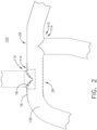
- FIG. 2 illustrates a partially-formed fluid conduit assembly 110, component 114, or T-joint 115 having an electroformed metallic layer 130 according to another aspect of the present disclosure.
- the partially-formed fluid conduit assembly 110 is similar to the partially-formed fluid conduit assembly 10; therefore, like parts will be identified with like numerals increased by 100, with it being understood that the description of the like parts of the partially-formed fluid conduit assembly 10 applies to the partially-formed fluid conduit assembly 110, unless otherwise noted.
- the electroformed metallic layer 130 can include at least a portion of the "forming" of the partially-formed fluid conduit assembly 110.
- FIG. 2 further illustrates in dotted outline, aspects of the sacrificial element 16 and the strengthening insert 18, for ease of understanding. As shown, at least the strengthening insert 18 can be fixed relative to the partially-formed fluid conduit assembly 110, the high stress area 26, the component 114 or the T-joint 115 or electroformed metallic layer 130, by way of the electroforming process.
- FIG. 3 illustrates a fully-formed fluid conduit assembly 111 (hereafter, "the fluid conduit assembly"), and dotted outline of the strengthening insert 18.
- the set of sacrificial elements 16 can be "sacrificed” or removed, as described above.
- aspects of the fluid conduit assembly 111 can include only the strengthening insert 18 and the electroformed metallic layer 130.
- FIG. 4 illustrates a schematic cross section of the high stress area 26 of FIG. 3 .
- a "high stress area" 26 can refer to an area, an interface, a joint 14 between elements, or a portion of the partially-formed fluid conduit assembly 10 expected, designed, or intended to experience higher stress compared with non-high-stress portions of the partially-formed fluid conduit assembly 10.
- the high stress area 26 can be a result of the geometric configuration of the partially-formed fluid conduit assembly 10, or connections thereto.
- Non-limiting examples of stress can include vibration, torque, pressure, thermal cycling, or the like, and can be based at least partially on an operating environment of the partially-formed fluid conduit assembly 10.
- the stress can affect the high stress area 26, the joint 14, or the partially-formed fluid conduit assembly 10, resulting in, for example, component failure, fatigue, deformation, damage, or the like.
- the stress can affect the high stress area 26 instantaneously during fluid conduit assembly 10 operations, or over an elongated period of time.
- a "high stress area" 26 can include a position or location that can to fail due to stresses experienced.
- the disposing of the strengthening insert 18 proximate or relative to the high stress area 26 can provide structural support or integrity to counter the stresses experienced at the high stress area 26. Stated another way, the strengthening insert 18 enables, provides for, or allows the fluid conduit assembly 10 or joint 14 to be better suited to resist failure at the high stress area 26 or at the joint 14.
- the electroforming process can be selected, controlled, selected, or the like, to ensure at least a minimal electroformed material thickness 132 over each exposed surface 20, 22 of the partially-formed fluid conduit assembly 10.
- One non-limiting example minimal electroformed material thickness 132 is 0.40 millimeters.
- the electroformed material thickness 132 can be less than the strengthening insert thickness 134.
- the primary structural support at the high stress area 26 can be provided by the strengthening insert 18, as opposed to the electroformed metallic layer 130, which the electroformed metallic layer 130 can provide the primary structural support for the non-high-stress areas.
- non-limiting aspects of the disclosure can be included wherein the electroforming material, or the electroformed material thickness 132 is selected based on desired operating aspects of the fluid conduit assembly 111, including but not limited to, pressure, fluid type, fluid temperature, the like, or a combination thereof.
- the strengthening insert 18 or strengthening insert thickness 134 can be selected based on the same electroformed material considerations or the expected stresses described herein, or a combination thereof.
- insert ends 36 can, in some instances, result in a higher current density during the electroforming process, producing a greater electroformed metallic layer thickness area 138 proximate to the insert ends 36.
- the insert ends 36 can be configured, selected, or the like, to include beveled, blended, or radial insert edges 36 configured or selected to ensure a uniform expected electroformed metallic layer 130 across all surfaces 20, 22 of the fluid conduit assembly 111, component 14, or T-joint 15.
- FIG. 5 illustrates another fluid conduit assembly 211 according to another aspect of the present disclosure.
- the fluid conduit assembly 210 is similar to the fluid conduit assembly 111; therefore, like parts will be identified with like numerals increased by 200, with it being understood that the description of the like parts of the partially-formed fluid conduit assembly 111 applies to the fluid conduit assembly 211, unless otherwise noted.
- the fluid conduit assembly 211 includes a component 214 in the form of a straight pipe wall 215.
- the strengthening insert 218 can comprise at least a partial ring or cylinder, or at least a partial ring or cylinder.
- FIG. 6 illustrates a schematic cross section of the high stress area 26 of FIG. 5 , included a dotted outline of the sacrificial material 216, for understanding. It will be understood that such sacrificial material 216 is removed prior to use of the component 214 having the strengthening insert 218.
- FIG. 7 illustrates another fluid conduit assembly 311 according to another aspect of the present disclosure.
- the fluid conduit assembly 311 is similar to the fluid conduit assembly 111, 211; therefore, like parts will be identified with like numerals increased by 300, with it being understood that the description of the like parts of the partially-formed fluid conduit assembly 111, 211 applies to the fluid conduit assembly 311, unless otherwise noted.
- the fluid conduit assembly 311 includes a component 314 in the form of an elbow 315 or elbow joint.
- the strengthening insert 318 can be positioned or configured to prevent extending or buckling of the joint 314.
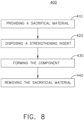
- FIG. 8 illustrates a flow chart demonstrating a method 400 of forming a strengthened component 214, 314 or assembly 111, 211, 311.
- the method 400 begins by forming or providing a sacrificial material 16, 216, 316 into a mold of the component 14, 214, 314 having an outer surface 20 at 410.
- the method 400 continues by disposing a strengthening insert 18, 218, 318 having an inner surface 24 and an outer surface 22 opposite and spaced from the inner surface 24 such that the strengthening insert 18, 218, 318 inner surface 24 abuts the outer surface 20 of the sacrificial material 16, 216, 316, at 420.
- the method 400 then proceeds to forming the component 214, 314 by way of electrodeposition of a metallic layer 130, 230, 330 over the exposed sacrificial material 16, 216, 316 outer surface 20 and the exposed strengthening insert 18, 218, 318 outer surface 22, at 430. Finally, the method 400 includes removing the sacrificial material 16, 216, 316 from the component 214, 314, as described herein, at 440.
- the method 400 can optionally include identifying a high stress area 26, 226, 326 prior to the disposing of the strengthening insert or disposing a strengthening insert having at least one of a beveled, blended, or radial insert edges.
- the method 400 can include forming the component or conduit by way of a set or series of metallic layers.
- the method 400 can include metalizing the exposed sacrificial material, the strengthening insert, or a combination thereof prior to the electrodeposition process.
- non-limiting aspects of the strengthened component such as the strengthened joint or strengthened walls
- aspects of the disclosure provide a method and apparatus forming a strengthened component, conduit, or joint.
- One advantage that can be realized is that the above described aspects have superior structural strength at critical joints or junctures, while reducing the total amount of electrodeposited materials or mass at non-critical areas of the element. A reduction in the total amount of electrodeposited materials or mass reduces the mass of the overall structure without compromising the integrity of the electrodeposited component.
- Another advantage over comparable elements or methods is that the above described aspects do not require brazing, welding, or doubling plates to reinforce or support the electroformed element, further reducing weight.
- Yet another advantage of the above described aspects is by utilizing the electrodeposition processes described, a minimal thickness of the metallic layer for component integrity is predictable during forming, further ensuring or exceeding conduit integrity without adding unnecessary mass or bulk.
- Non-limiting aspects of the above described features can be utilized to reduce weight by an electrodeposited component by ten to fifteen percent.
- important factors to address are size, weight, and reliability.
- the above described electrodeposited fluid conduit with strengthening insert results in a lower weight, smaller sized, increased performance, and increased integrity system. Reduced weight and size correlate to competitive advantages during flight.
Landscapes
- Engineering & Computer Science (AREA)
- Chemical & Material Sciences (AREA)
- Chemical Kinetics & Catalysis (AREA)
- Electrochemistry (AREA)
- Materials Engineering (AREA)
- Metallurgy (AREA)
- Organic Chemistry (AREA)
- Mechanical Engineering (AREA)
- General Engineering & Computer Science (AREA)
- Combustion & Propulsion (AREA)
- Fluid Mechanics (AREA)
- Physics & Mathematics (AREA)
- Rigid Pipes And Flexible Pipes (AREA)
- Shaping Metal By Deep-Drawing, Or The Like (AREA)
- Moulds For Moulding Plastics Or The Like (AREA)
- Branch Pipes, Bends, And The Like (AREA)
- Mounting, Exchange, And Manufacturing Of Dies (AREA)
Description
- Contemporary engines used in aircraft can include fluid passageways for providing flow from a fluid source to a fluid destination. In one non-limiting example, a bleed air system can receive pressurized bleed air from a compressor section of an engine and convey to a fluidly downstream component or system, such as an environmental control system. Additional fluid passageways can be utilized for carrying, transferring, or otherwise flowing fluid including, but not limited to, oil, coolant, water, fuel, or the like. In the example of an aircraft engine, the passageways can be exposed to high pressures, high temperatures, stresses, vibrations, thermal cycling, and the like. The passageway, or other component formed in a similar process, can be configured, designed, or arranged to provide reliable operation in the functional environment.
-
US 2,181,256 A discloses a core for use in electrodepositing a branched fitting. - In an aspect, the disclosure relates to a method of forming a strengthened fluid conduit, the method including providing a sacrificial material into a mold of the fluid conduit having an outer surface, disposing a strengthening insert having an inner surface and an outer surface, opposite and spaced from the inner surface, such that the strengthening insert inner surface abuts the mold outer surface, forming the fluid conduit by way of electrodeposition of a metallic layer over the exposed mold outer surface and the exposed strengthening insert outer surface, and removing the sacrificial material to define the fluid conduit.
- In the drawings:
-
FIG. 1 is an exploded perspective view of a molding and a strengthening insert for a component of a partially-formed fluid conduit, in accordance with various aspects described herein. -
FIG. 2 is a perspective view of a strengthened component of the partially-formed fluid conduit ofFIG. 1 , with dotted schematic outline of the strengthening insert, in accordance with various aspects described herein. -
FIG. 3 is a perspective view of a strengthened component of a fully-formed fluid conduit, with dotted schematic outline of the strengthening insert, in accordance with various aspects described herein. -
FIG. 4 is a schematic cross-sectional view of the strengthened component, taken along line IV-IV ofFIG. 3 , in accordance with various aspects described herein. -
FIG. 5 is a perspective view of another strengthened component in the form of a straight pipe, with dotted schematic outline of the strengthening insert, in accordance with various aspects described herein. -
FIG. 6 is a schematic cross-sectional view of the strengthened component, taken along line VI-VI ofFIG. 5 , in accordance with various aspects described herein. -
FIG. 7 is a perspective view of another strengthened component in the form of an elbow, with dotted schematic outline of the strengthening insert, in accordance with various aspects described herein. -
FIG. 8 is an example a flow chart diagram of demonstrating a method of for cooling a heat-generating module in accordance with various aspects described herein. - In specialized environments or installations, components, walls, conduits, passageways, or the like can be configured, arranged, tailored or selected based on particular requirements. Non-limiting aspects for particular requirements can include geometric configuration, space or volume considerations, weight considerations, or operational environment considerations. Non-limiting aspects of operational environment considerations can further include temperature, altitude, pressure, vibrations, thermal cycling, or the like.
- In one non-limiting example of a specialized application, a set of fluid conduits can be tailored for use in a bleed air system for an aircraft. The bleed air system can, for instance, supply or provide a passageway for airflow from an engine, a turbine, or from the environment external to the aircraft, to a downstream element. Non-limiting examples of the downstream element can utilize the airflow for heating, cooling, or pressurizing an element, system, or otherwise airflow-utilizing component. Bleed air system fluid conduits can further be exposed to operational environment considerations, such as those described herein.
- While aspects of the disclosure are described with reference to enclosed fluid conduits for a bleed air system of an aircraft, aspects of the disclosure can be implemented in any component, walls, conduits, passageways, or the like, regardless of environment or installation location. It will be understood that the present disclosure can have general applicability in non-aircraft applications, such as other mobile applications and non-mobile industrial, commercial, and residential applications as well.
- The use of the terms "proximal" or "proximally," either by themselves or in conjunction with other terms or elements, refers to a component being relatively closer to a reference point or element compared to another component.
- All directional references (e.g., radial, axial, upper, lower, upward, downward, left, right, lateral, front, back, top, bottom, above, below, vertical, horizontal, clockwise, counterclockwise) are only used for identification purposes to aid the reader's understanding of the disclosure, and do not create limitations, particularly as to the position, orientation, or use thereof. Connection references (e.g., attached, coupled, connected, and joined) are to be construed broadly and can include intermediate members between a collection of elements and relative movement between elements unless otherwise indicated. As such, connection references do not necessarily infer that two elements are directly connected and in fixed relation to each other.
- As used herein, a "joint" can refer to any connection or coupling between proximate components, including, but not limited to, the connection of components in line with one another, or at a relative angle to one another. Also as used herein, "sacrificial" can refer to an element, component, or material composition that can be removed. Non-limiting examples of "sacrificial" elements can include a meltable composition such as wax or plastic, or a dissolvable composition. In this sense, the "sacrificial" element can be removed by way of melting when exposed to a heating element, or dissolved when exposed to a dissolving composition. Additional or alternative non-limiting aspects of sacrificial element removal can be included, such as mechanical disassembly, or physically removing elements or sub-elements. The exemplary drawings are for purposes of illustration only and the dimensions, positions, order and relative sizes reflected in the drawings attached hereto can vary.
-
FIG. 1 illustrates a perspective view of a partially-formedfluid conduit assembly 10. The partially-formedfluid conduit assembly 10 can include a set of discrete orcontinuous conduit molds 12 including a set or series of sacrificial or moldedelements 16 arranged, configured, assembled, or the like, in a form or shape of a desired configuration, such as a portion of a bleed air system fluid conduit. Thesacrificial elements 16 include anouter surface 20. At least a subset of thesacrificial elements 16 can be molded to at least partially form acomponent 14, such as a wall, a housing, or a desired joining location between connected elements, such as a joint, illustrated as T-joints 15, or T-joint assemblies. As used herein, a "T-joint" denotes the "T" shaped configuration of adjoining arms, passages, conduits, or segments of theconduit molds 12 or partially-formedfluid conduit assembly 10. - Aspects of the partially-formed
fluid conduit assembly 10,component 14, or Tjoint 15 include a strengtheninginsert 18 having aninner surface 24, and anouter surface 22 opposite and spaced from theinner surface 24. Non-limiting aspects of the strengtheninginsert 18 can include a metallic composition, for example, to provide strength, rigidity, reliability, resilience, or the like. Non-limiting examples of strengthening insert 18 compositions can include, but are not limited to, nickel and nickel alloys, iron and iron alloys, aluminum, titanium, Inconel and Inconel alloys, of the like, or a combination thereof. In one non-limiting aspect, the increase in "strength" can be related to or associated with a corresponding increase ininsert 18 material hardness. The strengtheninginsert 18 can be disposed, positioned, configured, or arranged relative to at least one of the sacrificial moldedelements 16, the set ofconduit molds 12, or the partially-formedfluid conduit assembly 10,component 14, or T-joint 15. In one non-limiting example, at least a portion of theinner surface 24 of the strengtheninginsert 18 can abut at least a portion of theouter surface 20 of thesacrificial element 16. The strengtheninginsert 18 can be contoured, shaped, keyed, configured, or the like, such that the entireinner surface 24 abuts theouter surface 20 of thesacrificial element 16. The strengtheninginsert 18 can include spaced or opposinginsert ends 36. In the non-limiting examples, theinsert ends 36 can include straight edges. - Aspects of the partially-formed
fluid conduit assembly 10,component 14, or Tjoint 15 can be included wherein the strengtheninginsert 18 can be disposed relative to, located, or arranged proximate to a pre-identifiedhigh stress area 26 of the partially-formedfluid conduit assembly 10,component 14, or T-joint 14. - The partially-formed
fluid conduit assembly 10 ofFIG. 1 can be covered, enveloped, or encased in a metallic layer by way of an electrodeposition process. As used herein, "electrodeposition" can include any process for building, forming, growing, or otherwise creating a metallic layer over another substrate or base. Non-limiting examples of electrodeposition can include electroforming, electroless forming, electroplating, or a combination thereof. While the remainder of the disclosure is directed to electroforming, any and all electrodeposition processes are equally applicable. In one non-limiting example of an electroforming process, the partially-formedfluid conduit assembly 10 ofFIG. 1 can be submerged in an electrolytic liquid and electrically charged. The electric charge of the partially-formedfluid conduit assembly 10 can attract an oppositely charged electroforming material through the electrolytic solution. The attraction of the electroforming material to the partially-formedfluid conduit assembly 10 ultimately deposits the electroforming material on the exposed surfaces of the partially-formedfluid conduit assembly 10, creating an external metallic layer. Thus, the electroforming process can be utilized to form at least a portion of thecomponent 14, the T-joint 15, thehigh stress area 26, of the partially-formedfluid conduit assembly 10 by way of a metallic layer over the exposedouter surface 20 of the set ofsacrificial elements 16, theouter surface 22 of the strengtheningelement 18, or a combination thereof. - In one non-limiting example, electroforming material can include nickel and nickel alloys, iron and iron alloys, aluminum, titanium, Inconel and Inconel alloys, or the like, or a combination thereof. In another non-limiting example, at least a portion of the exposed
surfaces fluid conduit assembly 10 can include a metalized layer prior to the electroforming process. -
FIG. 2 illustrates a partially-formedfluid conduit assembly 110,component 114, or T-joint 115 having an electroformedmetallic layer 130 according to another aspect of the present disclosure. The partially-formedfluid conduit assembly 110 is similar to the partially-formedfluid conduit assembly 10; therefore, like parts will be identified with like numerals increased by 100, with it being understood that the description of the like parts of the partially-formedfluid conduit assembly 10 applies to the partially-formedfluid conduit assembly 110, unless otherwise noted. One difference is that the electroformedmetallic layer 130 can include at least a portion of the "forming" of the partially-formedfluid conduit assembly 110.FIG. 2 further illustrates in dotted outline, aspects of thesacrificial element 16 and the strengtheninginsert 18, for ease of understanding. As shown, at least the strengtheninginsert 18 can be fixed relative to the partially-formedfluid conduit assembly 110, thehigh stress area 26, thecomponent 114 or the T-joint 115 or electroformedmetallic layer 130, by way of the electroforming process. -
FIG. 3 illustrates a fully-formed fluid conduit assembly 111 (hereafter, "the fluid conduit assembly"), and dotted outline of the strengtheninginsert 18. After the forming of thefluid conduit assembly 111, as described herein, the set ofsacrificial elements 16, can be "sacrificed" or removed, as described above. Thus, aspects of thefluid conduit assembly 111 can include only the strengtheninginsert 18 and the electroformedmetallic layer 130. -
FIG. 4 illustrates a schematic cross section of thehigh stress area 26 ofFIG. 3 . As used herein, a "high stress area" 26 can refer to an area, an interface, a joint 14 between elements, or a portion of the partially-formedfluid conduit assembly 10 expected, designed, or intended to experience higher stress compared with non-high-stress portions of the partially-formedfluid conduit assembly 10. For instance, thehigh stress area 26 can be a result of the geometric configuration of the partially-formedfluid conduit assembly 10, or connections thereto. Non-limiting examples of stress can include vibration, torque, pressure, thermal cycling, or the like, and can be based at least partially on an operating environment of the partially-formedfluid conduit assembly 10. The stress can affect thehigh stress area 26, the joint 14, or the partially-formedfluid conduit assembly 10, resulting in, for example, component failure, fatigue, deformation, damage, or the like. The stress can affect thehigh stress area 26 instantaneously during fluid conduit assembly 10 operations, or over an elongated period of time. In this sense, a "high stress area" 26 can include a position or location that can to fail due to stresses experienced. Aspects of the disclosure can be included wherein the disposing of the strengtheninginsert 18 proximate or relative to thehigh stress area 26 can provide structural support or integrity to counter the stresses experienced at thehigh stress area 26. Stated another way, the strengtheninginsert 18 enables, provides for, or allows thefluid conduit assembly 10 or joint 14 to be better suited to resist failure at thehigh stress area 26 or at the joint 14. - As shown, the electroforming process can be selected, controlled, selected, or the like, to ensure at least a minimal
electroformed material thickness 132 over each exposedsurface fluid conduit assembly 10. One non-limiting example minimalelectroformed material thickness 132 is 0.40 millimeters. Also as shown, theelectroformed material thickness 132 can be less than the strengtheninginsert thickness 134. In this sense, the primary structural support at thehigh stress area 26 can be provided by the strengtheninginsert 18, as opposed to the electroformedmetallic layer 130, which the electroformedmetallic layer 130 can provide the primary structural support for the non-high-stress areas. Thus, non-limiting aspects of the disclosure can be included wherein the electroforming material, or theelectroformed material thickness 132 is selected based on desired operating aspects of thefluid conduit assembly 111, including but not limited to, pressure, fluid type, fluid temperature, the like, or a combination thereof. Likewise, non-limiting aspects of the disclosure can be included wherein the strengtheninginsert 18 or strengtheninginsert thickness 134 can be selected based on the same electroformed material considerations or the expected stresses described herein, or a combination thereof. - The use of the straight edge interface of the insert ends 36 can, in some instances, result in a higher current density during the electroforming process, producing a greater electroformed metallic
layer thickness area 138 proximate to the insert ends 36. Thus, aspects of the disclosure can be included wherein the insert ends 36 can be configured, selected, or the like, to include beveled, blended, or radial insert edges 36 configured or selected to ensure a uniform expected electroformedmetallic layer 130 across allsurfaces fluid conduit assembly 111,component 14, or T-joint 15. -
FIG. 5 illustrates anotherfluid conduit assembly 211 according to another aspect of the present disclosure. The fluid conduit assembly 210 is similar to thefluid conduit assembly 111; therefore, like parts will be identified with like numerals increased by 200, with it being understood that the description of the like parts of the partially-formedfluid conduit assembly 111 applies to thefluid conduit assembly 211, unless otherwise noted. One difference is that thefluid conduit assembly 211 includes acomponent 214 in the form of astraight pipe wall 215. As schematically illustrated in dotted outline beneath the electroformedmetallic layer 230, the strengtheninginsert 218 can comprise at least a partial ring or cylinder, or at least a partial ring or cylinder.FIG. 6 illustrates a schematic cross section of thehigh stress area 26 ofFIG. 5 , included a dotted outline of thesacrificial material 216, for understanding. It will be understood that suchsacrificial material 216 is removed prior to use of thecomponent 214 having the strengtheninginsert 218. -
FIG. 7 illustrates anotherfluid conduit assembly 311 according to another aspect of the present disclosure. Thefluid conduit assembly 311 is similar to thefluid conduit assembly fluid conduit assembly fluid conduit assembly 311, unless otherwise noted. One difference is that thefluid conduit assembly 311 includes acomponent 314 in the form of anelbow 315 or elbow joint. As schematically illustrated in dotted outline beneath the electroformedmetallic layer 330, the strengtheninginsert 318 can be positioned or configured to prevent extending or buckling of the joint 314. -
FIG. 8 illustrates a flow chart demonstrating amethod 400 of forming a strengthenedcomponent assembly method 400 begins by forming or providing asacrificial material component outer surface 20 at 410. Next, themethod 400 continues by disposing a strengtheninginsert inner surface 24 and anouter surface 22 opposite and spaced from theinner surface 24 such that the strengtheninginsert inner surface 24 abuts theouter surface 20 of thesacrificial material method 400 then proceeds to forming thecomponent metallic layer sacrificial material outer surface 20 and the exposed strengtheninginsert outer surface 22, at 430. Finally, themethod 400 includes removing thesacrificial material component - The sequence depicted is for illustrative purposes only and is not meant to limit the
method 400 in any way as it is understood that the portions of the method can proceed in a different logical order, additional or intervening portions can be included, or described portions of the method can be divided into multiple portions, or described portions of the method can be omitted without detracting from the described method. For example, themethod 400 can optionally include identifying ahigh stress area method 400 can include forming the component or conduit by way of a set or series of metallic layers. In yet another non-limiting example of themethod 400 can include metalizing the exposed sacrificial material, the strengthening insert, or a combination thereof prior to the electrodeposition process. - Many other possible embodiments and configurations in addition to that shown in the above figures are contemplated by the present disclosure. For example, non-limiting aspects of the strengthened component, such as the strengthened joint or strengthened walls, can be implemented in any wall, or electrodeposited component to reduce the total weight of the component without compromising the structural strength. Aspects of the disclosure provide a method and apparatus forming a strengthened component, conduit, or joint. One advantage that can be realized is that the above described aspects have superior structural strength at critical joints or junctures, while reducing the total amount of electrodeposited materials or mass at non-critical areas of the element. A reduction in the total amount of electrodeposited materials or mass reduces the mass of the overall structure without compromising the integrity of the electrodeposited component. Another advantage over comparable elements or methods is that the above described aspects do not require brazing, welding, or doubling plates to reinforce or support the electroformed element, further reducing weight.
- Yet another advantage of the above described aspects is by utilizing the electrodeposition processes described, a minimal thickness of the metallic layer for component integrity is predictable during forming, further ensuring or exceeding conduit integrity without adding unnecessary mass or bulk. Non-limiting aspects of the above described features can be utilized to reduce weight by an electrodeposited component by ten to fifteen percent. When designing aircraft components, important factors to address are size, weight, and reliability. The above described electrodeposited fluid conduit with strengthening insert results in a lower weight, smaller sized, increased performance, and increased integrity system. Reduced weight and size correlate to competitive advantages during flight.
- To the extent not already described, the different features and structures of the various embodiments can be used in combination with each other as desired. That one feature cannot be illustrated in all of the embodiments is not meant to be construed that it cannot be, but is done for brevity of description. Thus, the various features of the different embodiments can be mixed and matched as desired to form new embodiments, whether or not the new embodiments are expressly described. Combinations or permutations of features described herein are covered by this disclosure.
- This written description uses examples to disclose the invention, including the best mode, and also to enable any person skilled in the art to practice the invention, including making and using any devices or systems and performing any incorporated methods. The patentable scope of the disclosure is defined by the claims.
Claims (9)
- A method of forming a strengthened fluid conduit (14, 114, 214, 314), the method comprising:providing a sacrificial material into a mold (12) of the fluid conduit (14, 114, 214, 314) having an outer surface (20);disposing a strengthening insert (18) having an inner surface (24) and an outer surface (22), opposite and spaced from the inner surface (24), such that the strengthening insert (18) inner surface (24) abuts the mold (12) outer surface (20);forming the fluid conduit (14, 114, 214, 314) by way of electrodeposition of a metallic layer over the exposed mold (12) outer surface (20) and the exposed strengthening insert (18) outer surface (22); andremoving the sacrificial material to define the fluid conduit (14, 114, 214, 314).
- The method of claim 1, further comprising identifying a high stress area (26, 226, 326) of the fluid conduit prior to disposing the strengthening insert (18).
- The method of claim 2, wherein identifying the high stress area (26, 226, 326) includes identifying at least a portion of the fluid conduit(14, 114, 214, 314) to experience higher stress compared with non-high stress portions of the fluid conduit (14, 114, 214, 314).
- The method of claim 3, wherein disposing the strengthening insert (18) includes disposing the strengthening insert (18) relative to the mold (12) at a high stress area (26, 226, 326) of the fluid conduit (14, 114, 214, 314).
- The method of claim 4, wherein the fluid conduit (14, 114, 214, 314) is better suited to resist failure due to at least one of vibration, stress, or thermal cycling as compared to a fluid conduit (14, 114, 214, 314) without the strengthening insert (18).
- The method of any preceding claim, wherein at least a portion of the inner surface (24) of the strengthening insert (18) abuts at least a portion of the outer surface (20) of the sacrificial element (16), such that the inner surface (24) is flush with an inner surface of the electrodeposited metallic layer of the strengthened fluid conduit.
- The method of any preceding claim, wherein the providing the sacrificial material into a mold (12) of the fluid conduit (14, 114, 214, 314) includes forming the sacrificial material into a mold (12) of at least one of a T-joint or an elbow.
- The method of any preceding claim, wherein the strengthening insert (18) includes at least one of beveled, blended, or radial insert edges (36).
- The method of any preceding claim, wherein the electrodeposition of the metallic layer (130) includes forming a layer having a first thickness, less than a second thickness of the strengthening insert (18).
Priority Applications (1)
| Application Number | Priority Date | Filing Date | Title |
|---|---|---|---|
| EP23185956.2A EP4234907A3 (en) | 2017-04-28 | 2018-04-26 | Methods of forming a strengthened fluid conduit |
Applications Claiming Priority (1)
| Application Number | Priority Date | Filing Date | Title |
|---|---|---|---|
| US15/581,627 US11021802B2 (en) | 2017-04-28 | 2017-04-28 | Methods of forming a strengthened component |
Related Child Applications (2)
| Application Number | Title | Priority Date | Filing Date |
|---|---|---|---|
| EP23185956.2A Division EP4234907A3 (en) | 2017-04-28 | 2018-04-26 | Methods of forming a strengthened fluid conduit |
| EP23185956.2A Division-Into EP4234907A3 (en) | 2017-04-28 | 2018-04-26 | Methods of forming a strengthened fluid conduit |
Publications (2)
| Publication Number | Publication Date |
|---|---|
| EP3396026A1 EP3396026A1 (en) | 2018-10-31 |
| EP3396026B1 true EP3396026B1 (en) | 2023-08-23 |
Family
ID=62200220
Family Applications (2)
| Application Number | Title | Priority Date | Filing Date |
|---|---|---|---|
| EP23185956.2A Pending EP4234907A3 (en) | 2017-04-28 | 2018-04-26 | Methods of forming a strengthened fluid conduit |
| EP18169466.2A Active EP3396026B1 (en) | 2017-04-28 | 2018-04-26 | Methods of forming a strengthened fluid conduit |
Family Applications Before (1)
| Application Number | Title | Priority Date | Filing Date |
|---|---|---|---|
| EP23185956.2A Pending EP4234907A3 (en) | 2017-04-28 | 2018-04-26 | Methods of forming a strengthened fluid conduit |
Country Status (4)
| Country | Link |
|---|---|
| US (2) | US11021802B2 (en) |
| EP (2) | EP4234907A3 (en) |
| JP (1) | JP2018189235A (en) |
| CN (1) | CN108796557B (en) |
Families Citing this family (4)
| Publication number | Priority date | Publication date | Assignee | Title |
|---|---|---|---|---|
| US10731486B2 (en) * | 2018-03-29 | 2020-08-04 | Unison Industries, Llc | Duct assembly and method of forming |
| CN112404888A (en) * | 2020-09-23 | 2021-02-26 | 浙江德利福科技股份有限公司 | Forming process of stainless steel three-way pipe |
| US11725524B2 (en) | 2021-03-26 | 2023-08-15 | General Electric Company | Engine airfoil metal edge |
| US11767607B1 (en) | 2022-07-13 | 2023-09-26 | General Electric Company | Method of depositing a metal layer on a component |
Citations (1)
| Publication number | Priority date | Publication date | Assignee | Title |
|---|---|---|---|---|
| US2181256A (en) * | 1937-11-23 | 1939-11-28 | Northern Indiana Brass Co | Core for electrodepositing pipe couplings |
Family Cites Families (31)
| Publication number | Priority date | Publication date | Assignee | Title |
|---|---|---|---|---|
| US1575915A (en) * | 1922-05-01 | 1926-03-09 | Rome Radiation Company Inc | Radiator |
| US3464898A (en) | 1966-05-16 | 1969-09-02 | Us Army | Plastic foam mandrel for electroforming |
| GB1213821A (en) | 1967-04-12 | 1970-11-25 | Rolls Royce | Method of making a turbine blade |
| US3989602A (en) * | 1974-04-19 | 1976-11-02 | The United States Of America As Represented By The United States National Aeronautics And Space Administration | Method of making reinforced composite structures |
| JPS5125114U (en) * | 1974-08-13 | 1976-02-24 | ||
| JPS5257038A (en) | 1975-11-05 | 1977-05-11 | Nippon Electric Co | Production method of electrocastings |
| DE2947247A1 (en) * | 1979-11-23 | 1981-05-27 | Kabel- und Metallwerke Gutehoffnungshütte AG, 3000 Hannover | Flanged waveguide element mfr. - by fitting flanges to core with conductive surface before electroplating |
| GB2094350B (en) * | 1981-03-05 | 1984-12-19 | Electroform Pty Ltd | Electrodepositing metallic layers joining pipes |
| JPH02135795A (en) | 1988-11-17 | 1990-05-24 | Mitsubishi Electric Corp | Resist coater of substrate for printed circuit |
| JPH082464Y2 (en) | 1989-04-18 | 1996-01-29 | 臼井国際産業株式会社 | Fuel delivery pipe |
| JPH03243792A (en) * | 1990-02-22 | 1991-10-30 | Toshiba Corp | Formation of chromium coating |
| JPH0890561A (en) * | 1994-09-27 | 1996-04-09 | Ikex Kogyo:Kk | Method of manufacturing electroforming mold |
| US6027631A (en) | 1997-11-13 | 2000-02-22 | Novellus Systems, Inc. | Electroplating system with shields for varying thickness profile of deposited layer |
| US5945166A (en) | 1997-12-30 | 1999-08-31 | The United States Of America As Represented By The Administrator Of The National Aeronautics And Space Administration | Method for forming fiber reinforced composite bodies with graded composition and stress zones |
| DE10007995C2 (en) | 2000-02-22 | 2002-03-07 | Airbus Gmbh | Structural component, in particular for an aircraft and method for producing a structural component |
| US7597537B2 (en) | 2005-12-16 | 2009-10-06 | General Electric Company | Thermal control of gas turbine engine rings for active clearance control |
| US20070251825A1 (en) | 2006-04-28 | 2007-11-01 | Kenney Daniel R | Method of rapid insert backing |
| WO2010032255A1 (en) | 2008-09-22 | 2010-03-25 | Jewelex India Pvt. Ltd. | Hollow jewelry |
| EP2182096A1 (en) | 2008-10-28 | 2010-05-05 | Nivarox-FAR S.A. | Heterogeneous LIGA method |
| EP2549341A1 (en) | 2011-07-20 | 2013-01-23 | The Swatch Group Research and Development Ltd. | Method for implanting a decoration in a clock casing element deposited by electroplating and casing element manufactured according to said method |
| US20130199934A1 (en) * | 2012-02-06 | 2013-08-08 | United Technologies Corporation | Electroformed sheath |
| US10093434B2 (en) | 2012-03-29 | 2018-10-09 | Rosebank Engineering Pty Ltd | Methods for treating aircraft structures |
| US20140202170A1 (en) | 2012-11-20 | 2014-07-24 | United Technologies Corporation | Composite Articles and Methods |
| US9139923B2 (en) * | 2012-12-07 | 2015-09-22 | Apple Inc. | Electroformed housings for devices and methods for making the same |
| US20160238324A1 (en) | 2013-09-23 | 2016-08-18 | United Technologies Corporation | Method of generating support structure of tube components to become functional features |
| JP2015193116A (en) * | 2014-03-31 | 2015-11-05 | 株式会社アオイ | Pipe joint made of synthetic resin and method for producing the same |
| US20160003157A1 (en) | 2014-07-03 | 2016-01-07 | United Technologies Corporation | Additive manufactured tube assembly |
| EP2977835B1 (en) * | 2014-07-21 | 2017-06-28 | The Swatch Group Research and Development Ltd. | Welding by electroforming an electroformed timepiece shell |
| CN105525992B (en) | 2014-10-21 | 2020-04-14 | 联合工艺公司 | Additively manufactured tubular heat exchanger system with additively manufactured fairing |
| US10900136B2 (en) * | 2017-07-18 | 2021-01-26 | Honeywell International Inc. | Additive-based electroforming manufacturing methods and metallic articles produced thereby |
| US20200011455A1 (en) * | 2018-07-05 | 2020-01-09 | Unison Industries, Llc | Duct assembly and method of forming |
-
2017
- 2017-04-28 US US15/581,627 patent/US11021802B2/en active Active
-
2018
- 2018-04-25 JP JP2018083530A patent/JP2018189235A/en active Pending
- 2018-04-26 EP EP23185956.2A patent/EP4234907A3/en active Pending
- 2018-04-26 EP EP18169466.2A patent/EP3396026B1/en active Active
- 2018-04-27 CN CN201810392231.XA patent/CN108796557B/en active Active
-
2021
- 2021-05-28 US US17/333,248 patent/US12188142B2/en active Active
Patent Citations (1)
| Publication number | Priority date | Publication date | Assignee | Title |
|---|---|---|---|---|
| US2181256A (en) * | 1937-11-23 | 1939-11-28 | Northern Indiana Brass Co | Core for electrodepositing pipe couplings |
Also Published As
| Publication number | Publication date |
|---|---|
| US20180312987A1 (en) | 2018-11-01 |
| JP2018189235A (en) | 2018-11-29 |
| CN108796557B (en) | 2020-11-20 |
| CN108796557A (en) | 2018-11-13 |
| US12188142B2 (en) | 2025-01-07 |
| EP3396026A1 (en) | 2018-10-31 |
| US11021802B2 (en) | 2021-06-01 |
| EP4234907A3 (en) | 2024-02-28 |
| US20210285117A1 (en) | 2021-09-16 |
| EP4234907A2 (en) | 2023-08-30 |
Similar Documents
| Publication | Publication Date | Title |
|---|---|---|
| US12188142B2 (en) | Methods of forming a strengthened component | |
| JP6475681B2 (en) | Repair method using additive manufacturing for rotor blades and parts | |
| EP3401629B1 (en) | Heat exchanger | |
| US10823511B2 (en) | Manufacturing a heat exchanger using a material buildup process | |
| EP1905951B1 (en) | Structural members in a pedestal array | |
| EP2865981A1 (en) | Counter-flow heat exchange systems | |
| EP1843075B1 (en) | Repair of composite structures | |
| CN110319291B (en) | Duct assembly and method of forming | |
| CN108866581B (en) | Parts with different material properties | |
| EP3162469A1 (en) | Interlocking material transition zone with integrated film cooling | |
| EP3115670B1 (en) | Turbine engine couplings and methods for manufacturing turbine engine couplings | |
| CN110684993A (en) | Duct assembly and method of forming | |
| US20180057942A1 (en) | Methods for manufacturing a heat exchanger | |
| US12281733B2 (en) | Gimbal joints for bleed air systems | |
| CN102642093A (en) | Plating of ceramic matrix composite parts as joining method in gas turbine hardware | |
| EP3053689B1 (en) | Brazed joints and methods of forming brazed joints | |
| US10697075B2 (en) | Duct assembly and method of forming | |
| US11686012B2 (en) | Mandrel for electroforming | |
| US10731486B2 (en) | Duct assembly and method of forming | |
| Newman et al. | Novel ultra-high temperature metal seal with single crystal spring energizer | |
| GB2530794A (en) | Heat exchanger |
Legal Events
| Date | Code | Title | Description |
|---|---|---|---|
| PUAI | Public reference made under article 153(3) epc to a published international application that has entered the european phase |
Free format text: ORIGINAL CODE: 0009012 |
|
| STAA | Information on the status of an ep patent application or granted ep patent |
Free format text: STATUS: THE APPLICATION HAS BEEN PUBLISHED |
|
| AK | Designated contracting states |
Kind code of ref document: A1 Designated state(s): AL AT BE BG CH CY CZ DE DK EE ES FI FR GB GR HR HU IE IS IT LI LT LU LV MC MK MT NL NO PL PT RO RS SE SI SK SM TR |
|
| AX | Request for extension of the european patent |
Extension state: BA ME |
|
| STAA | Information on the status of an ep patent application or granted ep patent |
Free format text: STATUS: REQUEST FOR EXAMINATION WAS MADE |
|
| 17P | Request for examination filed |
Effective date: 20190429 |
|
| RBV | Designated contracting states (corrected) |
Designated state(s): AL AT BE BG CH CY CZ DE DK EE ES FI FR GB GR HR HU IE IS IT LI LT LU LV MC MK MT NL NO PL PT RO RS SE SI SK SM TR |
|
| STAA | Information on the status of an ep patent application or granted ep patent |
Free format text: STATUS: EXAMINATION IS IN PROGRESS |
|
| 17Q | First examination report despatched |
Effective date: 20210412 |
|
| GRAP | Despatch of communication of intention to grant a patent |
Free format text: ORIGINAL CODE: EPIDOSNIGR1 |
|
| STAA | Information on the status of an ep patent application or granted ep patent |
Free format text: STATUS: GRANT OF PATENT IS INTENDED |
|
| INTG | Intention to grant announced |
Effective date: 20230324 |
|
| GRAS | Grant fee paid |
Free format text: ORIGINAL CODE: EPIDOSNIGR3 |
|
| GRAA | (expected) grant |
Free format text: ORIGINAL CODE: 0009210 |
|
| STAA | Information on the status of an ep patent application or granted ep patent |
Free format text: STATUS: THE PATENT HAS BEEN GRANTED |
|
| AK | Designated contracting states |
Kind code of ref document: B1 Designated state(s): AL AT BE BG CH CY CZ DE DK EE ES FI FR GB GR HR HU IE IS IT LI LT LU LV MC MK MT NL NO PL PT RO RS SE SI SK SM TR |
|
| REG | Reference to a national code |
Ref country code: GB Ref legal event code: FG4D |
|
| P01 | Opt-out of the competence of the unified patent court (upc) registered |
Effective date: 20230724 |
|
| REG | Reference to a national code |
Ref country code: CH Ref legal event code: EP |
|
| REG | Reference to a national code |
Ref country code: DE Ref legal event code: R096 Ref document number: 602018055796 Country of ref document: DE |
|
| REG | Reference to a national code |
Ref country code: IE Ref legal event code: FG4D |
|
| REG | Reference to a national code |
Ref country code: LT Ref legal event code: MG9D |
|
| REG | Reference to a national code |
Ref country code: NL Ref legal event code: MP Effective date: 20230823 |
|
| REG | Reference to a national code |
Ref country code: AT Ref legal event code: MK05 Ref document number: 1602691 Country of ref document: AT Kind code of ref document: T Effective date: 20230823 |
|
| PG25 | Lapsed in a contracting state [announced via postgrant information from national office to epo] |
Ref country code: GR Free format text: LAPSE BECAUSE OF FAILURE TO SUBMIT A TRANSLATION OF THE DESCRIPTION OR TO PAY THE FEE WITHIN THE PRESCRIBED TIME-LIMIT Effective date: 20231124 |
|
| PG25 | Lapsed in a contracting state [announced via postgrant information from national office to epo] |
Ref country code: IS Free format text: LAPSE BECAUSE OF FAILURE TO SUBMIT A TRANSLATION OF THE DESCRIPTION OR TO PAY THE FEE WITHIN THE PRESCRIBED TIME-LIMIT Effective date: 20231223 |
|
| PG25 | Lapsed in a contracting state [announced via postgrant information from national office to epo] |
Ref country code: SE Free format text: LAPSE BECAUSE OF FAILURE TO SUBMIT A TRANSLATION OF THE DESCRIPTION OR TO PAY THE FEE WITHIN THE PRESCRIBED TIME-LIMIT Effective date: 20230823 Ref country code: RS Free format text: LAPSE BECAUSE OF FAILURE TO SUBMIT A TRANSLATION OF THE DESCRIPTION OR TO PAY THE FEE WITHIN THE PRESCRIBED TIME-LIMIT Effective date: 20230823 Ref country code: PT Free format text: LAPSE BECAUSE OF FAILURE TO SUBMIT A TRANSLATION OF THE DESCRIPTION OR TO PAY THE FEE WITHIN THE PRESCRIBED TIME-LIMIT Effective date: 20231226 Ref country code: NO Free format text: LAPSE BECAUSE OF FAILURE TO SUBMIT A TRANSLATION OF THE DESCRIPTION OR TO PAY THE FEE WITHIN THE PRESCRIBED TIME-LIMIT Effective date: 20231123 Ref country code: NL Free format text: LAPSE BECAUSE OF FAILURE TO SUBMIT A TRANSLATION OF THE DESCRIPTION OR TO PAY THE FEE WITHIN THE PRESCRIBED TIME-LIMIT Effective date: 20230823 Ref country code: LV Free format text: LAPSE BECAUSE OF FAILURE TO SUBMIT A TRANSLATION OF THE DESCRIPTION OR TO PAY THE FEE WITHIN THE PRESCRIBED TIME-LIMIT Effective date: 20230823 Ref country code: LT Free format text: LAPSE BECAUSE OF FAILURE TO SUBMIT A TRANSLATION OF THE DESCRIPTION OR TO PAY THE FEE WITHIN THE PRESCRIBED TIME-LIMIT Effective date: 20230823 Ref country code: IS Free format text: LAPSE BECAUSE OF FAILURE TO SUBMIT A TRANSLATION OF THE DESCRIPTION OR TO PAY THE FEE WITHIN THE PRESCRIBED TIME-LIMIT Effective date: 20231223 Ref country code: HR Free format text: LAPSE BECAUSE OF FAILURE TO SUBMIT A TRANSLATION OF THE DESCRIPTION OR TO PAY THE FEE WITHIN THE PRESCRIBED TIME-LIMIT Effective date: 20230823 Ref country code: GR Free format text: LAPSE BECAUSE OF FAILURE TO SUBMIT A TRANSLATION OF THE DESCRIPTION OR TO PAY THE FEE WITHIN THE PRESCRIBED TIME-LIMIT Effective date: 20231124 Ref country code: FI Free format text: LAPSE BECAUSE OF FAILURE TO SUBMIT A TRANSLATION OF THE DESCRIPTION OR TO PAY THE FEE WITHIN THE PRESCRIBED TIME-LIMIT Effective date: 20230823 Ref country code: AT Free format text: LAPSE BECAUSE OF FAILURE TO SUBMIT A TRANSLATION OF THE DESCRIPTION OR TO PAY THE FEE WITHIN THE PRESCRIBED TIME-LIMIT Effective date: 20230823 |
|
| PG25 | Lapsed in a contracting state [announced via postgrant information from national office to epo] |
Ref country code: PL Free format text: LAPSE BECAUSE OF FAILURE TO SUBMIT A TRANSLATION OF THE DESCRIPTION OR TO PAY THE FEE WITHIN THE PRESCRIBED TIME-LIMIT Effective date: 20230823 |
|
| PG25 | Lapsed in a contracting state [announced via postgrant information from national office to epo] |
Ref country code: ES Free format text: LAPSE BECAUSE OF FAILURE TO SUBMIT A TRANSLATION OF THE DESCRIPTION OR TO PAY THE FEE WITHIN THE PRESCRIBED TIME-LIMIT Effective date: 20230823 |
|
| PG25 | Lapsed in a contracting state [announced via postgrant information from national office to epo] |
Ref country code: SM Free format text: LAPSE BECAUSE OF FAILURE TO SUBMIT A TRANSLATION OF THE DESCRIPTION OR TO PAY THE FEE WITHIN THE PRESCRIBED TIME-LIMIT Effective date: 20230823 Ref country code: RO Free format text: LAPSE BECAUSE OF FAILURE TO SUBMIT A TRANSLATION OF THE DESCRIPTION OR TO PAY THE FEE WITHIN THE PRESCRIBED TIME-LIMIT Effective date: 20230823 Ref country code: ES Free format text: LAPSE BECAUSE OF FAILURE TO SUBMIT A TRANSLATION OF THE DESCRIPTION OR TO PAY THE FEE WITHIN THE PRESCRIBED TIME-LIMIT Effective date: 20230823 Ref country code: EE Free format text: LAPSE BECAUSE OF FAILURE TO SUBMIT A TRANSLATION OF THE DESCRIPTION OR TO PAY THE FEE WITHIN THE PRESCRIBED TIME-LIMIT Effective date: 20230823 Ref country code: DK Free format text: LAPSE BECAUSE OF FAILURE TO SUBMIT A TRANSLATION OF THE DESCRIPTION OR TO PAY THE FEE WITHIN THE PRESCRIBED TIME-LIMIT Effective date: 20230823 Ref country code: CZ Free format text: LAPSE BECAUSE OF FAILURE TO SUBMIT A TRANSLATION OF THE DESCRIPTION OR TO PAY THE FEE WITHIN THE PRESCRIBED TIME-LIMIT Effective date: 20230823 Ref country code: SK Free format text: LAPSE BECAUSE OF FAILURE TO SUBMIT A TRANSLATION OF THE DESCRIPTION OR TO PAY THE FEE WITHIN THE PRESCRIBED TIME-LIMIT Effective date: 20230823 |
|
| REG | Reference to a national code |
Ref country code: DE Ref legal event code: R097 Ref document number: 602018055796 Country of ref document: DE |
|
| PG25 | Lapsed in a contracting state [announced via postgrant information from national office to epo] |
Ref country code: IT Free format text: LAPSE BECAUSE OF FAILURE TO SUBMIT A TRANSLATION OF THE DESCRIPTION OR TO PAY THE FEE WITHIN THE PRESCRIBED TIME-LIMIT Effective date: 20230823 |
|
| PLBE | No opposition filed within time limit |
Free format text: ORIGINAL CODE: 0009261 |
|
| STAA | Information on the status of an ep patent application or granted ep patent |
Free format text: STATUS: NO OPPOSITION FILED WITHIN TIME LIMIT |
|
| 26N | No opposition filed |
Effective date: 20240524 |
|
| PG25 | Lapsed in a contracting state [announced via postgrant information from national office to epo] |
Ref country code: SI Free format text: LAPSE BECAUSE OF FAILURE TO SUBMIT A TRANSLATION OF THE DESCRIPTION OR TO PAY THE FEE WITHIN THE PRESCRIBED TIME-LIMIT Effective date: 20230823 |
|
| PG25 | Lapsed in a contracting state [announced via postgrant information from national office to epo] |
Ref country code: BG Free format text: LAPSE BECAUSE OF FAILURE TO SUBMIT A TRANSLATION OF THE DESCRIPTION OR TO PAY THE FEE WITHIN THE PRESCRIBED TIME-LIMIT Effective date: 20230823 |
|
| PG25 | Lapsed in a contracting state [announced via postgrant information from national office to epo] |
Ref country code: MC Free format text: LAPSE BECAUSE OF FAILURE TO SUBMIT A TRANSLATION OF THE DESCRIPTION OR TO PAY THE FEE WITHIN THE PRESCRIBED TIME-LIMIT Effective date: 20230823 |
|
| PG25 | Lapsed in a contracting state [announced via postgrant information from national office to epo] |
Ref country code: MC Free format text: LAPSE BECAUSE OF FAILURE TO SUBMIT A TRANSLATION OF THE DESCRIPTION OR TO PAY THE FEE WITHIN THE PRESCRIBED TIME-LIMIT Effective date: 20230823 Ref country code: BG Free format text: LAPSE BECAUSE OF FAILURE TO SUBMIT A TRANSLATION OF THE DESCRIPTION OR TO PAY THE FEE WITHIN THE PRESCRIBED TIME-LIMIT Effective date: 20230823 |
|
| REG | Reference to a national code |
Ref country code: CH Ref legal event code: PL |
|
| PG25 | Lapsed in a contracting state [announced via postgrant information from national office to epo] |
Ref country code: LU Free format text: LAPSE BECAUSE OF NON-PAYMENT OF DUE FEES Effective date: 20240426 |
|
| REG | Reference to a national code |
Ref country code: BE Ref legal event code: MM Effective date: 20240430 |
|
| PG25 | Lapsed in a contracting state [announced via postgrant information from national office to epo] |
Ref country code: LU Free format text: LAPSE BECAUSE OF NON-PAYMENT OF DUE FEES Effective date: 20240426 |
|
| PG25 | Lapsed in a contracting state [announced via postgrant information from national office to epo] |
Ref country code: BE Free format text: LAPSE BECAUSE OF NON-PAYMENT OF DUE FEES Effective date: 20240430 |
|
| PG25 | Lapsed in a contracting state [announced via postgrant information from national office to epo] |
Ref country code: BE Free format text: LAPSE BECAUSE OF NON-PAYMENT OF DUE FEES Effective date: 20240430 Ref country code: CH Free format text: LAPSE BECAUSE OF NON-PAYMENT OF DUE FEES Effective date: 20240430 |
|
| PG25 | Lapsed in a contracting state [announced via postgrant information from national office to epo] |
Ref country code: IE Free format text: LAPSE BECAUSE OF NON-PAYMENT OF DUE FEES Effective date: 20240426 |
|
| PGFP | Annual fee paid to national office [announced via postgrant information from national office to epo] |
Ref country code: DE Payment date: 20250319 Year of fee payment: 8 |
|
| PG25 | Lapsed in a contracting state [announced via postgrant information from national office to epo] |
Ref country code: CY Free format text: LAPSE BECAUSE OF FAILURE TO SUBMIT A TRANSLATION OF THE DESCRIPTION OR TO PAY THE FEE WITHIN THE PRESCRIBED TIME-LIMIT; INVALID AB INITIO Effective date: 20180426 |
|
| PG25 | Lapsed in a contracting state [announced via postgrant information from national office to epo] |
Ref country code: HU Free format text: LAPSE BECAUSE OF FAILURE TO SUBMIT A TRANSLATION OF THE DESCRIPTION OR TO PAY THE FEE WITHIN THE PRESCRIBED TIME-LIMIT; INVALID AB INITIO Effective date: 20180426 |
|
| PGFP | Annual fee paid to national office [announced via postgrant information from national office to epo] |
Ref country code: GB Payment date: 20260319 Year of fee payment: 9 |
|
| PGFP | Annual fee paid to national office [announced via postgrant information from national office to epo] |
Ref country code: FR Payment date: 20260320 Year of fee payment: 9 |