EP3396003A1 - Scum removal device and scum removal method - Google Patents
Scum removal device and scum removal method Download PDFInfo
- Publication number
- EP3396003A1 EP3396003A1 EP16878832.1A EP16878832A EP3396003A1 EP 3396003 A1 EP3396003 A1 EP 3396003A1 EP 16878832 A EP16878832 A EP 16878832A EP 3396003 A1 EP3396003 A1 EP 3396003A1
- Authority
- EP
- European Patent Office
- Prior art keywords
- steel strip
- hot
- suction
- liquid metal
- width direction
- Prior art date
- Legal status (The legal status is an assumption and is not a legal conclusion. Google has not performed a legal analysis and makes no representation as to the accuracy of the status listed.)
- Withdrawn
Links
Images





Classifications
-
- C—CHEMISTRY; METALLURGY
- C23—COATING METALLIC MATERIAL; COATING MATERIAL WITH METALLIC MATERIAL; CHEMICAL SURFACE TREATMENT; DIFFUSION TREATMENT OF METALLIC MATERIAL; COATING BY VACUUM EVAPORATION, BY SPUTTERING, BY ION IMPLANTATION OR BY CHEMICAL VAPOUR DEPOSITION, IN GENERAL; INHIBITING CORROSION OF METALLIC MATERIAL OR INCRUSTATION IN GENERAL
- C23C—COATING METALLIC MATERIAL; COATING MATERIAL WITH METALLIC MATERIAL; SURFACE TREATMENT OF METALLIC MATERIAL BY DIFFUSION INTO THE SURFACE, BY CHEMICAL CONVERSION OR SUBSTITUTION; COATING BY VACUUM EVAPORATION, BY SPUTTERING, BY ION IMPLANTATION OR BY CHEMICAL VAPOUR DEPOSITION, IN GENERAL
- C23C2/00—Hot-dipping or immersion processes for applying the coating material in the molten state without affecting the shape; Apparatus therefor
- C23C2/003—Apparatus
- C23C2/0032—Apparatus specially adapted for batch coating of substrate
- C23C2/00322—Details of mechanisms for immersing or removing substrate from molten liquid bath, e.g. basket or lifting mechanism
-
- F—MECHANICAL ENGINEERING; LIGHTING; HEATING; WEAPONS; BLASTING
- F27—FURNACES; KILNS; OVENS; RETORTS
- F27D—DETAILS OR ACCESSORIES OF FURNACES, KILNS, OVENS OR RETORTS, IN SO FAR AS THEY ARE OF KINDS OCCURRING IN MORE THAN ONE KIND OF FURNACE
- F27D3/00—Charging; Discharging; Manipulation of charge
- F27D3/15—Tapping equipment; Equipment for removing or retaining slag
- F27D3/1545—Equipment for removing or retaining slag
- F27D3/1554—Equipment for removing or retaining slag for removing the slag from the surface of the melt
- F27D3/1572—Equipment for removing or retaining slag for removing the slag from the surface of the melt by suction
-
- C—CHEMISTRY; METALLURGY
- C23—COATING METALLIC MATERIAL; COATING MATERIAL WITH METALLIC MATERIAL; CHEMICAL SURFACE TREATMENT; DIFFUSION TREATMENT OF METALLIC MATERIAL; COATING BY VACUUM EVAPORATION, BY SPUTTERING, BY ION IMPLANTATION OR BY CHEMICAL VAPOUR DEPOSITION, IN GENERAL; INHIBITING CORROSION OF METALLIC MATERIAL OR INCRUSTATION IN GENERAL
- C23C—COATING METALLIC MATERIAL; COATING MATERIAL WITH METALLIC MATERIAL; SURFACE TREATMENT OF METALLIC MATERIAL BY DIFFUSION INTO THE SURFACE, BY CHEMICAL CONVERSION OR SUBSTITUTION; COATING BY VACUUM EVAPORATION, BY SPUTTERING, BY ION IMPLANTATION OR BY CHEMICAL VAPOUR DEPOSITION, IN GENERAL
- C23C2/00—Hot-dipping or immersion processes for applying the coating material in the molten state without affecting the shape; Apparatus therefor
-
- C—CHEMISTRY; METALLURGY
- C23—COATING METALLIC MATERIAL; COATING MATERIAL WITH METALLIC MATERIAL; CHEMICAL SURFACE TREATMENT; DIFFUSION TREATMENT OF METALLIC MATERIAL; COATING BY VACUUM EVAPORATION, BY SPUTTERING, BY ION IMPLANTATION OR BY CHEMICAL VAPOUR DEPOSITION, IN GENERAL; INHIBITING CORROSION OF METALLIC MATERIAL OR INCRUSTATION IN GENERAL
- C23C—COATING METALLIC MATERIAL; COATING MATERIAL WITH METALLIC MATERIAL; SURFACE TREATMENT OF METALLIC MATERIAL BY DIFFUSION INTO THE SURFACE, BY CHEMICAL CONVERSION OR SUBSTITUTION; COATING BY VACUUM EVAPORATION, BY SPUTTERING, BY ION IMPLANTATION OR BY CHEMICAL VAPOUR DEPOSITION, IN GENERAL
- C23C2/00—Hot-dipping or immersion processes for applying the coating material in the molten state without affecting the shape; Apparatus therefor
- C23C2/003—Apparatus
- C23C2/0034—Details related to elements immersed in bath
- C23C2/00342—Moving elements, e.g. pumps or mixers
- C23C2/00344—Means for moving substrates, e.g. immersed rollers or immersed bearings
-
- C—CHEMISTRY; METALLURGY
- C23—COATING METALLIC MATERIAL; COATING MATERIAL WITH METALLIC MATERIAL; CHEMICAL SURFACE TREATMENT; DIFFUSION TREATMENT OF METALLIC MATERIAL; COATING BY VACUUM EVAPORATION, BY SPUTTERING, BY ION IMPLANTATION OR BY CHEMICAL VAPOUR DEPOSITION, IN GENERAL; INHIBITING CORROSION OF METALLIC MATERIAL OR INCRUSTATION IN GENERAL
- C23C—COATING METALLIC MATERIAL; COATING MATERIAL WITH METALLIC MATERIAL; SURFACE TREATMENT OF METALLIC MATERIAL BY DIFFUSION INTO THE SURFACE, BY CHEMICAL CONVERSION OR SUBSTITUTION; COATING BY VACUUM EVAPORATION, BY SPUTTERING, BY ION IMPLANTATION OR BY CHEMICAL VAPOUR DEPOSITION, IN GENERAL
- C23C2/00—Hot-dipping or immersion processes for applying the coating material in the molten state without affecting the shape; Apparatus therefor
- C23C2/003—Apparatus
- C23C2/0035—Means for continuously moving substrate through, into or out of the bath
-
- C—CHEMISTRY; METALLURGY
- C23—COATING METALLIC MATERIAL; COATING MATERIAL WITH METALLIC MATERIAL; CHEMICAL SURFACE TREATMENT; DIFFUSION TREATMENT OF METALLIC MATERIAL; COATING BY VACUUM EVAPORATION, BY SPUTTERING, BY ION IMPLANTATION OR BY CHEMICAL VAPOUR DEPOSITION, IN GENERAL; INHIBITING CORROSION OF METALLIC MATERIAL OR INCRUSTATION IN GENERAL
- C23C—COATING METALLIC MATERIAL; COATING MATERIAL WITH METALLIC MATERIAL; SURFACE TREATMENT OF METALLIC MATERIAL BY DIFFUSION INTO THE SURFACE, BY CHEMICAL CONVERSION OR SUBSTITUTION; COATING BY VACUUM EVAPORATION, BY SPUTTERING, BY ION IMPLANTATION OR BY CHEMICAL VAPOUR DEPOSITION, IN GENERAL
- C23C2/00—Hot-dipping or immersion processes for applying the coating material in the molten state without affecting the shape; Apparatus therefor
- C23C2/003—Apparatus
- C23C2/0038—Apparatus characterised by the pre-treatment chambers located immediately upstream of the bath or occurring locally before the dipping process
-
- C—CHEMISTRY; METALLURGY
- C23—COATING METALLIC MATERIAL; COATING MATERIAL WITH METALLIC MATERIAL; CHEMICAL SURFACE TREATMENT; DIFFUSION TREATMENT OF METALLIC MATERIAL; COATING BY VACUUM EVAPORATION, BY SPUTTERING, BY ION IMPLANTATION OR BY CHEMICAL VAPOUR DEPOSITION, IN GENERAL; INHIBITING CORROSION OF METALLIC MATERIAL OR INCRUSTATION IN GENERAL
- C23C—COATING METALLIC MATERIAL; COATING MATERIAL WITH METALLIC MATERIAL; SURFACE TREATMENT OF METALLIC MATERIAL BY DIFFUSION INTO THE SURFACE, BY CHEMICAL CONVERSION OR SUBSTITUTION; COATING BY VACUUM EVAPORATION, BY SPUTTERING, BY ION IMPLANTATION OR BY CHEMICAL VAPOUR DEPOSITION, IN GENERAL
- C23C2/00—Hot-dipping or immersion processes for applying the coating material in the molten state without affecting the shape; Apparatus therefor
- C23C2/003—Apparatus
- C23C2/0038—Apparatus characterised by the pre-treatment chambers located immediately upstream of the bath or occurring locally before the dipping process
- C23C2/004—Snouts
-
- C—CHEMISTRY; METALLURGY
- C23—COATING METALLIC MATERIAL; COATING MATERIAL WITH METALLIC MATERIAL; CHEMICAL SURFACE TREATMENT; DIFFUSION TREATMENT OF METALLIC MATERIAL; COATING BY VACUUM EVAPORATION, BY SPUTTERING, BY ION IMPLANTATION OR BY CHEMICAL VAPOUR DEPOSITION, IN GENERAL; INHIBITING CORROSION OF METALLIC MATERIAL OR INCRUSTATION IN GENERAL
- C23C—COATING METALLIC MATERIAL; COATING MATERIAL WITH METALLIC MATERIAL; SURFACE TREATMENT OF METALLIC MATERIAL BY DIFFUSION INTO THE SURFACE, BY CHEMICAL CONVERSION OR SUBSTITUTION; COATING BY VACUUM EVAPORATION, BY SPUTTERING, BY ION IMPLANTATION OR BY CHEMICAL VAPOUR DEPOSITION, IN GENERAL
- C23C2/00—Hot-dipping or immersion processes for applying the coating material in the molten state without affecting the shape; Apparatus therefor
- C23C2/04—Hot-dipping or immersion processes for applying the coating material in the molten state without affecting the shape; Apparatus therefor characterised by the coating material
- C23C2/06—Zinc or cadmium or alloys based thereon
-
- C—CHEMISTRY; METALLURGY
- C23—COATING METALLIC MATERIAL; COATING MATERIAL WITH METALLIC MATERIAL; CHEMICAL SURFACE TREATMENT; DIFFUSION TREATMENT OF METALLIC MATERIAL; COATING BY VACUUM EVAPORATION, BY SPUTTERING, BY ION IMPLANTATION OR BY CHEMICAL VAPOUR DEPOSITION, IN GENERAL; INHIBITING CORROSION OF METALLIC MATERIAL OR INCRUSTATION IN GENERAL
- C23C—COATING METALLIC MATERIAL; COATING MATERIAL WITH METALLIC MATERIAL; SURFACE TREATMENT OF METALLIC MATERIAL BY DIFFUSION INTO THE SURFACE, BY CHEMICAL CONVERSION OR SUBSTITUTION; COATING BY VACUUM EVAPORATION, BY SPUTTERING, BY ION IMPLANTATION OR BY CHEMICAL VAPOUR DEPOSITION, IN GENERAL
- C23C2/00—Hot-dipping or immersion processes for applying the coating material in the molten state without affecting the shape; Apparatus therefor
- C23C2/325—Processes or devices for cleaning the bath
-
- C—CHEMISTRY; METALLURGY
- C23—COATING METALLIC MATERIAL; COATING MATERIAL WITH METALLIC MATERIAL; CHEMICAL SURFACE TREATMENT; DIFFUSION TREATMENT OF METALLIC MATERIAL; COATING BY VACUUM EVAPORATION, BY SPUTTERING, BY ION IMPLANTATION OR BY CHEMICAL VAPOUR DEPOSITION, IN GENERAL; INHIBITING CORROSION OF METALLIC MATERIAL OR INCRUSTATION IN GENERAL
- C23C—COATING METALLIC MATERIAL; COATING MATERIAL WITH METALLIC MATERIAL; SURFACE TREATMENT OF METALLIC MATERIAL BY DIFFUSION INTO THE SURFACE, BY CHEMICAL CONVERSION OR SUBSTITUTION; COATING BY VACUUM EVAPORATION, BY SPUTTERING, BY ION IMPLANTATION OR BY CHEMICAL VAPOUR DEPOSITION, IN GENERAL
- C23C2/00—Hot-dipping or immersion processes for applying the coating material in the molten state without affecting the shape; Apparatus therefor
- C23C2/34—Hot-dipping or immersion processes for applying the coating material in the molten state without affecting the shape; Apparatus therefor characterised by the shape of the material to be treated
- C23C2/36—Elongated material
- C23C2/40—Plates; Strips
Definitions
- the present disclosure relates to a scum removal device and a scum removal method to remove scum floating at the inside of a snout configuring equipment to manufacture hot-dip plated steel sheet.
- Patent Document 1 Japanese Patent Application Laid-Open ( JP-A) No. 2010-229530 (hereinafter referred to as Patent Document 1) discloses a countermeasure to remove floating matter by providing discharge port and suction port pairs, with one pair provided on each of the two thickness direction sides of a steel strip.
- JP-A No. 2000-064015 (hereinafter referred to as Patent Document 2) and JP-A No. 2014-114484 (hereinafter referred to as Patent Document 3) disclose configurations in which a discharge port is provided on one width direction side of a steel strip to discharge a liquid metal for hot dipping, and a suction port is provided on the other width direction side of the steel strip to suck in the liquid metal for hot dipping.
- Patent Document 4 JP-A No. 2003-293107 discloses a configuration in which two discharge ports are provided on one width direction side of a steel strip, and one suction port is provided on the other width direction side of the steel strip.
- Patent Document 5 JP-A No. 2014-201817 discloses a configuration in which a dross transfer device is provided to generate waves by moving a plate shaped member to and fro.
- Patent Document 2 and Patent Document 3 provide technology to form a flow with directionality from one width direction side of the steel strip to the other width direction side thereof.
- an accompanying current is generated at the hot-dip plating bath surface as the steel strip is drawn into the hot-dip galvanizing liquid.
- the hot-dip zinc plating liquid is simply discharged from one width direction side of the steel strip toward the other width direction side of the steel strip, the effect of the accompanying current will dominate at the suction port side, and scum will flow toward the steel strip surface.
- Patent Document 2 proposes a configuration in which a divider plate is install parallel to the steel strip, scum adhered to the divider plate surface readily detaches from the divider plate due to the fast flow in the regulated flow direction, and surface defects are readily generated by the detached scum adhering to the steel strip surface.
- Patent Document 2 proposes technology to forcibly generate a bath surface flow in a substantially orthogonal direction away from the surface of the steel strip.
- a problem arises in that inflowing scum readily adheres at the two steel strip width direction end portions of the steel strip.
- the suction port is provided on an extension line in the width direction, and so there is a concern that the flow from the two discharge ports toward the suction port might draw progressively closer to the steel strip as it flows from the discharge ports toward the suction port.
- the present disclosure provides a scum removal device and a scum removal method capable of suppressing scum floating on a hot-dip plating bath surface from adhering to a steel strip by suppressing over the entire width of the steel strip.
- scum adhered to snout wall faces in the vicinity of a plating bath surface pose a particular problem in causing steel strip defects when the scum dislodges and adheres to the steel strip.
- the inventors et al. have discovered that this problem can be prevented by making the scum adhered to the snout wall face at the boundary between the snout inner face and the bath surface more difficult to dislodge, and controlling flow at the bath surface such that even if scum is dislodged, the dislodged scum does not flow to the steel strip surface.
- a scum removal device includes: a snout, the snout being inserted into a liquid metal for hot dipping in a hot-dip plating pot such that a hot-dip plating bath surface is present inside the snout; a discharge section, the discharge section being disposed on an extension line of a steel strip entry position on the hot-dip plating bath surface at one side in a steel strip width direction, and discharging the liquid metal for hot dipping; and a suction section, the suction section being disposed on the extension line on the hot-dip plating bath surface at another side in the steel strip width direction, and sucking in the liquid metal for hot dipping; the suction section being configured by a first suction portion and a second suction portion, and the first suction portion and the second suction portion being disposed separated from each other at each side of the steel strip width direction extension line of the steel strip entry position on the hot-dip plating bath surface.
- the scum removal device enables scum floating on the surface of a hot-dip plating bath to be suppressed from adhering to a steel strip.
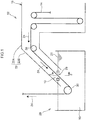
- Fig. 1 illustrates an example of a schematic configuration of plating equipment 12 provided with one mode of a scum removal device 10 and a scum removal method according to the present exemplary embodiment.
- the plating equipment 12 is equipment to plate a steel strip 14 having a thickness of from 1 mm to 3 mm, for example.
- the plating equipment 12 includes a continuous reduction annealing furnace 16 to anneal the steel strip 14, and a hot-dip plating pot 20 storing a liquid metal for hot dipping 18.
- molten zinc is employed as the liquid metal for hot dipping 18 and the steel strip 14 is galvanized by immersion, however, there is no limitation thereto.
- the steel strip 14 can be tinned by employing molten tin, or the steel strip 14 can be aluminum plated by employing molten aluminum.
- a snout 22 extends from the reduction annealing furnace 16.
- the snout 22 includes an extension section 22A extending in a horizontal direction from the reduction annealing furnace 16, and an inclined section 22B extending from the extension section 22A diagonally downward toward the hot-dip plating pot 20.
- the snout 22 is formed in a rectangular tube shape surrounding the steel strip 14. The leading end portion of the snout 22 is inserted into the liquid metal for hot dipping 18 in the hot-dip plating pot 20.
- the internal space of the snout 22 is thereby isolated from the exterior, such that the snout 22 configures a pipeline connecting the reduction annealing furnace 16 and the hot-dip plating pot 20 together in an airtight manner.
- the internal space of the snout 22 is filled with a reducing gas to suppress oxidation etc. of the steel strip 14, and the steel strip 14 is immersed in the liquid metal for hot dipping 18 in the hot-dip plating pot 20 without coming into contact with air.
- a feed roll 26 is provided at the base end side of the inclined section 22B of the snout 22, to change a conveyance direction 24 of the steel strip 14 diagonally downward.
- the steel strip 14 that has been annealed in the reduction annealing furnace 16 is conveyed with its length direction along the snout 22, and drawn into a hot-dip plating bath surface 28 inside the snout 22.
- the conveyance path of the steel strip 14 inside the snout 22 is determined by the feed roll 26 and a guide roll 30 disposed inside the hot-dip plating pot 20, thereby stabilizing the position of entry of the steel strip 14 into the hot-dip plating bath surface 28 of the liquid metal for hot dipping 18.
- the conveyance direction 24 of the steel strip 14 is then changed upward by the guide roll 30, and the steel strip 14 is fed out from the hot-dip plating pot 20 to a subsequent process.
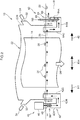
- Fig. 2 is a schematic cross-section illustrating in outline a state inside the snout 22, as viewed along line 2-2 of Fig. 1 .
- Observation windows 32 are provided at the two sides of the inclined section 22B of the snout 22 in a steel strip width direction KH.
- the steel strip width direction KH is a direction orthogonal to the conveyance direction 24 of the steel strip 14.
- Cameras 34 are provided at the observation windows 32.
- the cameras 34 image the way in which the steel strip 14 is drawn into the hot-dip plating bath surface 28 at a steel strip entry position 29.
- the steel strip entry position 29 is a position at the intersection of the steel strip 14 and the hot-dip plating bath surface 28, or is a position where the steel strip 14 and the hot-dip plating bath surface 28 are due to intersect, and forms a straight line with length along the steel strip width direction KH in plan view.
- Zinc that vaporizes from the liquid metal for hot dipping 18 in a plating process condenses and adheres to the inner face of the snout 22. Any part of the adhered zinc falling, for example due to vibration caused by oscillation of the bath surface, becomes scum 36 floating on the hot-dip plating bath surface 28.
- the scum 36 adheres to the steel strip 14 and is a cause of surface defects.
- the scum removal device 10, described in detail below, is accordingly provided inside the snout 22 to suppress quality defects caused by the scum 36.
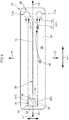
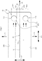
- Fig. 3 is an outline cross-section illustrating a state of the hot-dip plating bath surface 28 inside the snout 22 as viewed from above (a horizontal section of the snout 22 and the steel strip 14).
- the steel strip 14 moves in a direction away from the viewer and into the page in Fig. 3 .
- the reference numeral 60 indicates an extension line of the steel strip entry position 29, and the extension line 60 is a straight line passing through a thickness direction center of the steel strip 14, and is a hypothetical straight line extension of the steel strip width direction KH.
- the extension line 60 is at a position substantially equidistant from one inner wall face 22D and another inner wall face 22E.
- a discharge device 40 is provided on the extension line 60 of the steel strip 14 at one width direction side H1 of the steel strip 14 (the left side in the drawings).
- the discharge device 40 includes a circular tube shaped discharge pipe 42, bent into a U-shaped profile.
- the discharge pipe 42 includes a vertical outside pipe section 42A disposed outside the snout 22 and extending in a vertical direction, and a communication section 42B extending from a lower end portion of the vertical outside pipe section 42A toward the inside of the snout 22.
- the discharge pipe 42 includes a vertical inside pipe section 42C extending upward from the leading end of the communication section 42B and disposed at the inside of the snout 22.
- the base end portion of the vertical outside pipe section 42A of the discharge pipe 42 extends above the hot-dip plating bath surface 28.
- a motor 46 is provided at the base end of the vertical outside pipe section 42A.
- a screw 48 is provided on the drive shaft of the motor 46, and the screw 48 is rotationally driven inside the liquid metal for hot dipping 18.
- An intake port 50 is formed to the vertical outside pipe section 42A on the opposite side to the snout 22 at a height position corresponding to the screw 48.
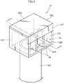
- a cuboid shaped discharge nozzle 52 is provided at a leading end portion of the vertical inside pipe section 42C to discharge the liquid metal for hot dipping 18 at the hot-dip plating bath surface 28 inside the snout 22.
- a description follows of the discharge nozzle 52, taking the direction the liquid metal for hot dipping 18 is discharged in toward the steel strip 14 side, as described later, as being the front of the discharge nozzle 52.
- the discharge nozzle 52 includes a bottom plate 52B formed with a circular hole 52A in communication with the vertical inside pipe section 42C, and side walls 52C extending upward at two side edges of the bottom plate 52B.
- the discharge nozzle 52 also includes a rear wall 52D extending upward at a rear edge of the bottom plate 52B, and a top plate 52E provided so as to be contiguous to upper edges of the side walls 52C and the rear wall 52D.
- An extension plate 52F extends from a front edge of the top plate 52E toward the bottom plate 52B side.
- a discharge section 56 is formed between the extension plate 52F and the bottom plate 52B, opening onto the steel strip 14 side. As illustrated in Fig. 5 , the extension plate 52F suppresses ripples from being formed in the liquid metal for hot dipping 18 as it is discharged from the discharge section 56.
- a pair of flow regulation plates 58 are installed upright on the bottom plate 52B.
- the flow regulation plates 58 are formed in rectangular shapes, and are sufficiently tall for upper portions of the flow regulation plates 58 to be supported by the extension plate 52F.
- the discharge nozzle 52 is disposed such that a lower side of the discharge nozzle 52 is at a position in the liquid metal for hot dipping 18.
- the flow of the liquid metal for hot dipping 18 discharged from the discharge section 56 is regulated with enhanced straight line directionality along the steel strip width direction KH by the flow regulation plates 58 and the side walls 52C, as illustrated in Fig. 3 and Fig. 6 .
- the flow speed (the steel strip width direction KH component) of the liquid metal for hot dipping 18 in the vicinity of the steel strip 14 is raised in comparison to cases lacking flow regulation, and the scum 36 is quickly washed away.
- the discharge section 56 is disposed on the extension line 60 from the steel strip 14 extending along the steel strip width direction KH, with approximately the width direction center of the discharge section 56 positioned on the extension line 60 of the steel strip 14.
- the discharge device 40 discharges the liquid metal for hot dipping 18, taken in through the intake port 50 at the outside of the snout 22, through the discharge section 56 from the one width direction side H1 of the steel strip 14, toward the steel strip 14 side, such that the liquid metal for hot dipping 18 flows along the hot-dip plating bath surface 28.
- a suction device 62 is provided at another width direction side H2 of the steel strip 14 (the right side in the drawing).
- the suction device 62 includes a circular tube shaped suction pipe 64 bent into a U-shaped profile.
- the suction pipe 64 includes a vertical outside pipe 64A disposed outside the snout 22 and extending in a vertical direction, and a communication section 64B extending toward the snout 22 inside from a lower end portion of the vertical outside pipe 64A.
- the suction pipe 64 also includes a vertical inside pipe 64C disposed inside the snout 22 and extending upward from the leading end of the communication section 64B.
- the base end portion of the vertical outside pipe 64A of the suction pipe 64 is disposed so as to extend above the hot-dip plating bath surface 28.
- An exhaust port 66 is opened in the base end portion of the vertical outside pipe 64A on the opposite to the snout 22, at a height position in the liquid metal for hot dipping 18.
- a gas supply pipe 68 is inserted into a base end opening of the vertical outside pipe 64A to supply nitrogen gas (N 2 ) fed from a supply source, not illustrated in the drawings.
- the leading end of the gas supply pipe 68 reaches a lower portion of the vertical outside pipe 64A.
- the liquid metal for hot dipping 18 is exhausted through the exhaust port 66 by the nitrogen gas being supplied through the gas supply pipe 68, thereby lowering the internal pressure inside the vertical outside pipe 64A.
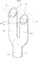
- the liquid metal for hot dipping 18 inside the vertical inside pipe 64C flows into the vertical outside pipe 64A through the communication section 64B due to the lowered internal pressure.
- a first suction nozzle 71A and a second suction nozzle 71B, as illustrated in Fig. 3 and Fig. 7 are thereby configured at an end portion of the vertical inside pipe 64C.
- a first suction portion 72 and a second suction portion 74 are configured by respective openings of the first suction nozzle 71A and the second suction nozzle 71B.
- a suction section 64H (see Fig. 3 ) to suck in the liquid metal for hot dipping 18 is configured by the first suction portion 72 and the second suction portion 74.
- Reference here to a suction section indicates openings where nozzles (the first suction nozzle 71A and the second suction nozzle 71B) are provided to suck in the liquid metal for hot dipping 18.
- the first suction nozzle 71A and the second suction nozzle 71B may, for example, be configured by the respective suction pipes 64 of a pair of the suction devices 62.
- the suction pipes 64 are each provided along the up-down direction so as to be separated from each other in a steel strip thickness direction KT (see Fig. 7 ).
- a first pipe 64F is configured at an upper end portion of the vertical inside pipe 64C of one of the suction pipes 64.
- a second pipe 64G is configured at an upper end portion of the vertical inside pipe 64C of the other of the suction pipes 64.
- the leading end portion of the first pipe 64F is cut at an inclination on the steel strip entry position 29 side thereof (see Fig. 7 ).
- the plane of the opening is inclined so as to open toward the steel strip entry position 29 side at the hot-dip plating bath surface 28. Namely, the plane of the opening at the leading end portion of the first pipe 64F intersects at an angle with the hot-dip plating bath surface 28.
- the leading end portion of the first pipe 64F accordingly configures the first suction nozzle 71A including the first suction portion 72 to suck in the liquid metal for hot dipping 18.
- a leading end portion of the second pipe 64G is also cut at an inclination on the steel strip entry position 29 side thereof (see Fig. 7 ).
- the plane of the opening is inclined so as to open toward the steel strip entry position 29 side at the hot-dip plating bath surface 28. Namely, the plane of the opening at the leading end portion of the second pipe 64G intersects at an angle with the hot-dip plating bath surface 28.
- the leading end portion of the second pipe 64G accordingly configures the second suction nozzle 71B including the second suction portion 74 to suck in the liquid metal for hot dipping 18.
- the suction section 64H is thereby configured by the first suction portion 72 and the second suction portion 74, to suck in the scum 36 (see Fig. 3 ) floating on the liquid metal for hot dipping 18, together with the liquid metal for hot dipping 18, so as to remove the scum 36.
- the first pipe 64F and the second pipe 64G may also be configured as bifurcations branching from a main pipe 641 provided in the liquid metal for hot dipping 18 (a first modified example).
- the configuration of the suction device 62 can be simplified in this case by configuring the main pipe 641 at the end portion of the vertical inside pipe 64C.
- configurations of the suction nozzles 71A, 71B are not limited to the profiles given above.
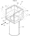
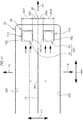
- An example of a second modified example is illustrated in Fig. 10 (in which only a first suction nozzle 71C is illustrated) and Fig. 11 . Note that the same or equivalent portions to those of Fig. 3 and Fig. 7 are appended with the same reference numerals in Fig. 11 , and duplicate description is omitted thereof.
- the first suction nozzle 71C is provided at the leading end portion of the vertical inside pipe 64C.
- the first suction nozzle 71C includes a bottom plate 70B including a circular hole 70A in communication with the vertical inside pipe 64C, and side walls 70C extending upward from the two side edges of the bottom plate 70B.
- the first suction nozzle 71C includes a rear wall 70D provided extending upward from a rear edge of the bottom plate 70B, with edges of the rear wall 70D contiguous to the side walls 70C.
- the side walls 70C configure flow regulation plates that function to regulate flow of the sucked in liquid metal for hot dipping 18 along the steel strip width direction KH.
- a second suction nozzle 71D is also configured in a similar manner to the first suction nozzle 71C.
- an opening width SH1 of the first suction nozzle 71C (an opening width SH2 of the second suction nozzle 71D) is fixed, and does not depend on the height of the hot-dip plating bath surface 28.
- the suction nozzles 71C, 71D equipped with flow regulating function by the side walls 70C are employed so as to enable the sucking-in direction to be aligned with the steel strip width direction KH.
- the first suction nozzle 71A or 71C and the second suction nozzle 71B or 71D are disposed such that the approximate center between the pairs of suction nozzles 71A, 71B, 71C, 71D is positioned on the extension line 60 of the steel strip 14.
- the first suction portion 72 of the first suction nozzle 71A or 71C is disposed on one thickness direction side T1 of the steel strip 14 about a boundary at the extension line 60 of the steel strip 14, and sucks in the liquid metal for hot dipping 18 at the hot-dip plating bath surface 28 on the one thickness direction side T1 of the extension line 60 of the steel strip 14.
- the second suction portion 74 of the second suction nozzle 71B or 71D is disposed on the other thickness direction side T2 about a boundary at the extension line 60 of the steel strip 14, and sucks in the liquid metal for hot dipping 18 at the hot-dip plating bath surface 28 on the other thickness direction side T2 of the extension line 60 of the steel strip 14.
- Fig. 6 is a diagram indicating the one width direction side H1 of the snout 22.
- the discharge section 56 formed by the discharge nozzle 52 of the discharge device 40 is disposed such that the width direction center of the discharge section 56 in the steel strip thickness direction KT is substantially aligned with the extension line 60 of the steel strip 14, and an opening width TH of the discharge section 56 in the steel strip thickness direction KT is set to no less than 50 mm.
- a discharge region TR of the discharge section 56 is determined by the opening width TH and the placement of the discharge section 56.
- the discharge section 56 is also disposed so as to be separated by no less than 100 mm from the inner faces of the snout 22 facing the steel strip 14 on entry at the steel strip entry position 29. Namely, a separation distance SR1 from one end of the discharge section 56 to the one inner wall face 22D of the snout 22 is no less than 100 mm. Moreover, a separation distance SR2 from the other end of the discharge section 56 to the other inner wall face 22E of the snout 22 is no less than 100 mm, and the separation distance SR1 and the separation distance SR2 are set so as to be substantially the same dimensions as each other.
- Fig. 7 and Fig. 11 are diagrams illustrating the other width direction side H2 of the snout 22.
- the steel strip thickness direction KT center between the first suction nozzle 71A, 71C and the second suction nozzle 71B, 71D of the suction device 62 is disposed so as to be substantially aligned with the extension line 60 of the steel strip 14.
- the first suction nozzle 71A, 71C is set to adjust the amount projecting out from the hot-dip plating bath surface 28.
- the opening width SH1 of the first suction portion 72 of the first suction nozzle 71A, 71C is thereby no less than 40 mm at the height position of the hot-dip plating bath surface 28.
- a separation distance CR1 from an edge of the first suction nozzle 71A, 71C on the side of the extension line 60 of the steel strip 14 to the extension line 60 is no less than 30 mm. Note that due to the first suction nozzle 71C including the side walls 70C, as described above, the opening width SH1 and the separation distance CR1 are fixed, and do not depend on the height of the hot-dip plating bath surface 28.
- the second suction nozzle 71B, 71D is set to adjust the amount thereof projecting out from the hot-dip plating bath surface 28.
- the opening width SH2 of the second suction portion 74 of the second suction nozzle 71B, 71D is thereby no less than 40 mm.
- a separation distance CR2 from an edge of the second suction nozzle 71B, 71D on the side of the extension line 60 the steel strip 14 to the extension line 60 is no less than 30 mm.
- the opening width SH2 and the separation distance CR2 are fixed, and do not depend on the height of the hot-dip plating bath surface 28.
- the respective suction nozzles 71A to 71D of the present exemplary embodiment are provided at positions with approximate line symmetry about the extension line 60.
- the center of the first suction portion 72 is positioned at the one thickness direction side T1 of the end of the discharge section 56 on the one thickness direction side T1.
- the center of the second suction portion 74 is positioned at the one thickness direction side T1 of the end of the discharge section 56 on the other thickness direction side T2.
- a fourth modified example is illustrated in Fig. 15 and Fig. 16 .
- a suction nozzle 70 is provided at a leading end portion of a vertical inside pipe 46C.
- the suction nozzle 70 includes a bottom plate 70B including a circular hole 70A in communication with the vertical inside pipe 64C, and side walls 70C extending in a diagonally upward direction from the two side edges of the bottom plate 70B, with an upper section of each side wall 70C extending in a vertical direction.
- the suction nozzle 70 includes a rear wall 70D provided extending upward from a rear edge of the bottom plate 70B with edges of the rear wall 70D contiguous to the side walls 70C, and a front wall 70E provided extending upward from a front edge of the bottom plate 70B with edges of the bottom plate 70B contiguous to the side walls 70C, so as to form a box shape open upward.
- Rectangular shaped cutouts 70F are formed at the two sides of an upper edge of the front wall 70E.
- a first suction portion 72 and a second suction portion 74 are formed by the respective cutouts 70F, as examples of a first opening and a second opening open on the steel strip 14 side.
- a blocking portion 76 is configured at a location between the two suction portions 72, 74 by a remaining portion of the upper section of the front wall 70E.
- each of the suction portions 72, 74 is disposed so as to be at a position below the hot-dip plating bath surface 28.
- Upper edge portions of the side walls 70C and the rear wall 70D, and an upper edge portion of the blocking portion 76 of the front wall 70E, extend to above the hot-dip plating bath surface 28. This enables the scum 36 floating on the liquid metal for hot dipping 18 to be sucked in with the liquid metal for hot dipping 18 through the first suction portion 72 and the second suction portion 74, and to be removed.
- the liquid metal for hot dipping 18 is obstructed from being sucked in at the blocking portion 76.
- the approximate center of the suction nozzle 70 in the width direction is disposed at a position on the extension line 60 of the steel strip 14.
- the first suction portion 72 of the suction nozzle 70 is disposed at the one steel strip 14 thickness direction side T1 of the extension line 60 of the steel strip 14, and sucks in the liquid metal for hot dipping 18 on the one thickness direction side T1 of the extension line 60 of the steel strip 14 at the hot-dip plating bath surface 28.
- the second suction portion 74 is disposed at the other thickness direction side T2 of the extension line 60 of the steel strip 14, and sucks in the liquid metal for hot dipping 18 on the other thickness direction side T2 of the extension line 60 of the steel strip 14 at the hot-dip plating bath surface 28.
- the suction nozzle 70 is disposed such that the center of the suction nozzle 70 in the width direction, this being the steel strip thickness direction KT, is substantially aligned with the extension line 60 of the steel strip 14. The location of the suction nozzle 70 on the extension line 60 of the steel strip 14 is blocked off by the blocking portion 76.
- the opening width SH1 of the first suction portion 72 is no less than 40 mm, and the separation distance CR1 from the edge of the suction nozzle 70 on the width direction center side to the width direction center of the suction nozzle 70 is no less than 30 mm.
- the opening width SH2 of the second suction portion 74 is no less than 40 mm, and the separation distance CR2 from the edge of the suction nozzle 70 on the width direction center side to the width direction center of the suction nozzle 70 is no less than 30 mm.
- the suction nozzle 70 of the present exemplary embodiment has substantial line symmetry about the width direction center, namely, about the extension line 60.
- the center of the first suction portion 72 is positioned at the one thickness direction side T1 of the one thickness direction side T1 end of the discharge section 56.
- the center of the second suction portion 74 is positioned at the other thickness direction side T2 of the other thickness direction side T2 end of the discharge section 56.
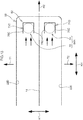
- Fig. 17 illustrates a most basic configuration in which a discharge section 56 lacking a function to regulate the flow of discharged liquid metal for hot dipping 18 is provided at one width direction side H1 of a steel strip 14, and a suction section 84 is provided at another width direction side H2 of the steel strip 14 (Comparative Example 1).
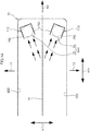
- Fig. 18 illustrates a configuration in which a discharge nozzle 52 including a flow regulating function performed by the flow regulation plates 58 and side walls 52C illustrated in Fig. 4 is employed in place of the discharge section 56 of Fig. 17 (Comparative Example 2).
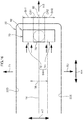
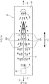
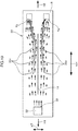
- Fig. 19 illustrates an Example of the present exemplary embodiment including the two suction portions 72, 74 instead of the suction section 84 of Fig. 18 .
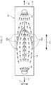
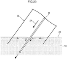
- Fig. 20 is a diagram illustrating a state of the hot-dip plating bath surface 28 in the snout 22.
- An accompanying current is generated at the hot-dip plating bath surface 28 in the snout 22 by the liquid metal for hot dipping 18 being drawn in together with the steel strip 14 being fed in the conveyance direction 24.
- the liquid metal for hot dipping 18 is discharged in a radial pattern in concentric waves from the discharge section 56.
- an average flow is generated in the snout 22 across the entire range of the snout 22 in the short direction, which is the steel strip thickness direction KT.
- the flow of the liquid metal for hot dipping 18 accordingly has a comparatively high flow speed at the wall faces of the snout 22.
- the scum 36a adhered to the wall faces of the snout 22 is accordingly readily dislodged.
- the flow speed in the steel strip width direction KH in the vicinity of the steel strip 14 is roughly the same as in the vicinity of the wall faces of the snout 22.
- the flow speed in the steel strip width direction KH is thus not fast enough to cause the scum 36a to flow in a direction away from an end portion in the steel strip width direction KH.
- the scum 36a is therefore sucked in toward the steel strip 14 by the accompanying current of the liquid metal for hot dipping 18 being drawn in together with the steel strip 14, and adheres to the steel strip 14, resulting in defects.
- the flow speed in the steel strip width direction KH in the snout 22 is slower at the vicinity of the wall faces of the snout 22, suppressing the scum 36b from detaching from the wall faces.
- the flow speed in the steel strip width direction KH is high in the vicinity of the steel strip 14, causing the scum 36b to resist the accompanying current and flow in the steel strip width direction KH.
- the scum 36b can accordingly be suppressed from adhering to the steel strip 14 in comparison to the basic configuration of Fig. 17 (Comparative Example 1).
- the scum 36b sometimes adheres to the steel strip 14 on the suction section 84 side.
- liquid metal for hot dipping taken in from outside the snout 22 is discharged through the discharge section 56, and to form a flow of the liquid metal for hot dipping 18 in the snout 22.
- the scum 36 floating inside the snout 22 is thereby caused to flow toward the first suction portion 72 and the second suction portion 74.
- the center of the first suction portion 72 is positioned at the one thickness direction side T1 of the one thickness direction side T1 end of the discharge section 56.
- the center of the second suction portion 74 is positioned at the other thickness direction side T2 of the other thickness direction side T2 end of the discharge section 56.
- the liquid metal for hot dipping 18 discharged by the two width direction sides of the discharge section 56 can also be caused to flow in a direction away from the steel strip 14. This enables the floating scum 36 to be suppressed from adhering to the steel strip 14.
- the first suction portion 72 and the second suction portion 74 are disposed separated by no less than 30 mm away from the extension line 60 of the steel strip 14 (CR1 ⁇ 30 mm, CR2 ⁇ 30 mm).
- the flow of the liquid metal for hot dipping 18 discharged by the two width direction sides of the discharge section 56 can be suppressed from approaching the steel strip 14 due to the accompanying current. This enables the floating scum 36 to be suppressed from adhering to the steel strip 14.
- the respective opening widths SH1, SH2 of the first suction portion 72 and the second suction portion 74 are no less than 40 mm.
- the region in which the liquid metal for hot dipping 18 is sucked through the suction portions 72, 74 is widened, thereby raising the removal efficiency of the floating scum 36.
- the suction direction can be aligned with the steel strip width direction KH.
- the scum adhered to the inner wall faces 22D, 22E can accordingly be suppressed from dislodging, and also the rate of suction of the liquid metal for hot dipping 18 at the suction portions 72, 74 can be increased in comparison to cases lacking a flow regulating function.
- the discharge section 56 is separated by no less than 100 mm from the inner faces of the snout 22 that face the steel strip 14 entering at the steel strip entry position 29 (SR1 ⁇ 100 mm, SR2 ⁇ 100 mm).
- SR1 ⁇ 100 mm, SR2 ⁇ 100 mm the inner faces of the snout 22 that face the steel strip 14 entering at the steel strip entry position 29.
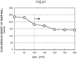
- Fig. 21 illustrates results of water modeling tests (tests in a water tank) to measure changes in flow speed in the vicinity of an inner face of the snout 22 when the separation distance SR1 from one width direction end of the discharge section 56 to the one inner wall face 22D of the snout 22 is changed.
- the flow speed in the vicinity of the inner face was confirmed to be lowered by making the separation distance SR1 no less than 100 mm, and an effect of preventing dislodging of the scum 36 adhered to the inner face can be expected.
- the opening width TH of the discharge section 56 was made no less than 50 mm.
- the discharge rate of liquid metal for hot dipping from the discharge section 56 was thereby increased in comparison to cases in which the opening width TH was less than 50 mm, enabling an enhanced effect of preventing adherence of the scum 36 to the steel strip 14.
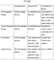
- Fig. 22 is a table of test results. This table illustrates a first and second comparative example, and a first and second example.
- the first comparative example is a comparative example to test the provision of a discharge section lacking a flow regulating function at the one width direction side HI, and provision of a single suction section on the extension line 60 of the steel strip 14 at the other width direction side H2 (configuration of Fig. 17 ).
- a flow regulating function (configuration of Fig. 18 ) was provided to the discharge section of the first comparative example.
- the first exemplary embodiment is an example to test provision of a discharge section lacking a flow regulating function at the one width direction side HI, and provision of suction portions separated from each other and forming a pair at the one thickness direction side T1 and the other thickness direction side T2 about the extension line 60 of the steel strip 14 at the other width direction side H2.
- a dramatic improvement in the amount adhering was achieved.
- the second exemplary embodiment is the first exemplary embodiment with a flow regulating function provided to the discharge section (configuration of Fig. 19 ). In the second exemplary embodiment scum did not adhere to the steel strip 14.
- a scum removal device includes: a snout, the snout being inserted into a liquid metal for hot dipping in a hot-dip plating pot such that a hot-dip plating bath surface is present inside the snout; a discharge section, the discharge section being disposed on an extension line of a steel strip entry position on the hot-dip plating bath surface at one side in a steel strip width direction, and discharging the liquid metal for hot dipping; and a suction section, the suction section being disposed on the extension line on the hot-dip plating bath surface at another side in the steel strip width direction, and sucking in the liquid metal for hot dipping; the suction section being configured by a first suction portion and a second suction portion, and the first suction portion and the second suction portion being disposed separated from each other at each side of the steel strip width direction extension line of the steel strip entry position on the hot-dip plating bath surface.
- a scum removal device is the first aspect, wherein the discharge section includes a flow regulation plate that regulates flow of the discharged liquid metal for hot dipping so as to flow in the steel strip width direction.
- a scum removal device is the first or second aspect, wherein the first suction portion and the second suction portion include flow regulation plates that regulate flow of the discharged liquid metal for hot dipping so as to flow in the steel strip width direction.
- a scum removal device is the first or second aspect, wherein: the first suction portion is configured by a first pipe including an opening at a pipe leading end where the liquid metal for hot dipping is sucked in, a plane of the opening being inclined so as to open toward a steel strip entry position side; and the second suction portion is configured by a second pipe including an opening at a pipe leading end where the liquid metal for hot dipping is sucked in, a plane of the opening being inclined so as to open toward the steel strip entry position side.
- a scum removal device is the fourth aspect, wherein the first pipe and the second pipe are formed as bifurcations branching from a main pipe.
- a scum removal device is any one of the first to third aspects, wherein: the suction section is configured by a suction nozzle including a front wall facing a steel strip entry position side; the front wall of the suction nozzle is formed with: a blocking portion disposed on the extension line at the other side in the steel strip width direction and obstructing sucking in of the liquid metal for hot dipping, a first opening provided at a portion of the front wall at one side of the blocking portion and open toward the steel strip entry position side, and a second opening provided at a portion of the front wall at another side of the blocking portion and open toward the steel strip entry position side; and the first suction portion is configured by the first opening, and the second suction portion is configured by the second opening.
- a scum removal device is any one of the first to sixth aspects, wherein the discharge section is disposed at a separation of no less than 100 mm from an inner face of the snout extending along the steel strip entry position.
- a scum removal method is used in a snout inserted into a liquid metal for hot dipping in a hot-dip plating pot such that a hot-dip plating bath surface is present inside the snout, the method comprising: discharging the liquid metal for hot dipping at an extension line of a steel strip entry position on the hot-dip plating bath surface at one side in a steel strip width direction; and sucking in the liquid metal for hot dipping at another side in the steel strip width direction on the hot-dip plating bath surface, at positions separated from each other at each side of the steel strip width direction extension line of the steel strip entry position on the hot-dip plating bath surface.
- a first other aspect is "a scum removal device including a suction nozzle to remove scum floating on a hot-dip galvanizing bath, inside a snout connecting a reduction annealing furnace to a pot of molten zinc in equipment to manufacture hot-dip galvanized steel sheet, by sucking in the scum together with molten zinc at a hot-dip galvanizing bath surface, and the suction nozzle including a first suction nozzle disposed on one face side of a steel strip passing through inside the snout, and a second suction nozzle disposed on another face side of the steel strip.
- a second other aspect is "the scum removal device of the first other aspect, wherein the first and second suction nozzles are disposed at a snout inner end portion in a width direction of the steel strip passing through inside the snout".
- a third other aspect is "the scum removal device of the second other aspect, wherein the first and/or the second suction nozzle is disposed at least separated in the steel strip thickness direction by no less than 30 mm from the width direction extension line of the steel strip".
- a fourth other aspect is "the scum removal device of the second or third other aspect, wherein the first and/or the second suction nozzle has an opening size of at least no less than 40 mm in the steel strip thickness direction".
Landscapes
- Chemical & Material Sciences (AREA)
- Engineering & Computer Science (AREA)
- Mechanical Engineering (AREA)
- Chemical Kinetics & Catalysis (AREA)
- Materials Engineering (AREA)
- Metallurgy (AREA)
- Organic Chemistry (AREA)
- General Engineering & Computer Science (AREA)
- Coating With Molten Metal (AREA)
Abstract
Description
- The present disclosure relates to a scum removal device and a scum removal method to remove scum floating at the inside of a snout configuring equipment to manufacture hot-dip plated steel sheet.
- In equipment to manufacture hot-dip galvanized steel sheet, if zinc vaporized from a hot-dip galvanizing bath condenses on and adheres to inner walls of a snout (steel strip direct feed pipeline connecting a reduction annealing furnace to a pot of molten zinc), the zinc sometimes forms a scum powder that floats on the galvanizing bath.
- Technology is accordingly employed in which a discharge port and a suction port are provided at each of the two steel strip width direction sides of the steel strip inside the snout, a flow is formed in the steel strip width direction, and scum is sucked out through the suction port. However, this is not sufficiently effective, and so technology like the following has been proposed.
- For example, Japanese Patent Application Laid-Open (
JP-A) No. 2010-229530 - Moreover,
JP-A No. 2000-064015 JP-A No. 2014-114484 - Moreover,
JP-A No. 2003-293107 - Moreover, in order to address issues when an injection nozzle is provided for injecting liquid metal for hot dipping,
JP-A No. 2014-201817 - However, in the method of
Patent Document 1, a flow is generated from one discharge port toward the suction port provided in the steel strip width direction thereof, and a flow is generated from the one discharge port toward the suction port provided in the steel strip thickness direction thereof. This results in part of the scum flowing toward the steel strip surface, and in particular at the two sides in the steel strip width direction, scum readily adheres to the steel strip surface on the side where the discharge port is provided. - Moreover, due to the discharge port being close to the snout wall face, the flow at the wall face is fast, and dislodges scum that has adhered to the wall face. This scum flows out on the bath surface, and readily adheres to the steel strip. This becomes a particular issue because of the large size of the scum dislodged from the snout inner wall face adjacent to the plating bath.
- Moreover, Patent Document 2 and Patent Document 3 provide technology to form a flow with directionality from one width direction side of the steel strip to the other width direction side thereof. However, an accompanying current is generated at the hot-dip plating bath surface as the steel strip is drawn into the hot-dip galvanizing liquid. Thus, if the hot-dip zinc plating liquid is simply discharged from one width direction side of the steel strip toward the other width direction side of the steel strip, the effect of the accompanying current will dominate at the suction port side, and scum will flow toward the steel strip surface.
- Moreover, although Patent Document 2 proposes a configuration in which a divider plate is install parallel to the steel strip, scum adhered to the divider plate surface readily detaches from the divider plate due to the fast flow in the regulated flow direction, and surface defects are readily generated by the detached scum adhering to the steel strip surface.
- Moreover, Patent Document 2 proposes technology to forcibly generate a bath surface flow in a substantially orthogonal direction away from the surface of the steel strip. However, due to a strong flow being generated so as to flow from the two width direction ends of the steel strip in a direction toward the plate width direction center, a problem arises in that inflowing scum readily adheres at the two steel strip width direction end portions of the steel strip.
- In the configuration of Patent Document 4, the suction port is provided on an extension line in the width direction, and so there is a concern that the flow from the two discharge ports toward the suction port might draw progressively closer to the steel strip as it flows from the discharge ports toward the suction port.
- Moreover, in the configuration of
Patent Document 5, waves are generated by moving a plate shaped member to and fro with the dross transfer device, and so floating scum is simply displaced up and down together with the generated waves, and it is not possible to cause active scum flow. - The present disclosure provides a scum removal device and a scum removal method capable of suppressing scum floating on a hot-dip plating bath surface from adhering to a steel strip by suppressing over the entire width of the steel strip.
- As a result of diligent investigations, the inventors have discovered that scum adhered to snout wall faces in the vicinity of a plating bath surface pose a particular problem in causing steel strip defects when the scum dislodges and adheres to the steel strip. The inventors et al. have discovered that this problem can be prevented by making the scum adhered to the snout wall face at the boundary between the snout inner face and the bath surface more difficult to dislodge, and controlling flow at the bath surface such that even if scum is dislodged, the dislodged scum does not flow to the steel strip surface.
- A scum removal device according to a first aspect of the present disclosure includes: a snout, the snout being inserted into a liquid metal for hot dipping in a hot-dip plating pot such that a hot-dip plating bath surface is present inside the snout; a discharge section, the discharge section being disposed on an extension line of a steel strip entry position on the hot-dip plating bath surface at one side in a steel strip width direction, and discharging the liquid metal for hot dipping; and a suction section, the suction section being disposed on the extension line on the hot-dip plating bath surface at another side in the steel strip width direction, and sucking in the liquid metal for hot dipping; the suction section being configured by a first suction portion and a second suction portion, and the first suction portion and the second suction portion being disposed separated from each other at each side of the steel strip width direction extension line of the steel strip entry position on the hot-dip plating bath surface.
- The scum removal device according to the present disclosure enables scum floating on the surface of a hot-dip plating bath to be suppressed from adhering to a steel strip.
-
-
Fig. 1 is a schematic cross-section of an example of steel strip plating equipment, as viewed from the side. -
Fig. 2 is a schematic cross-section of the interior of a snout, as viewed along the direction of line 2-2 ofFig. 1 . -
Fig. 3 is a schematic cross-section of a hot-dip plating bath surface inside a snout, as viewed along the direction of line 3-3 ofFig. 2 . -
Fig. 4 is a schematic perspective view illustrating a discharge nozzle. -
Fig. 5 is a cross-section illustrating a discharge nozzle, taken on line 5-5 ofFig. 4 . -
Fig. 6 is an enlarged schematic cross-section of one side ofFig. 3 . -
Fig. 7 is an enlarged schematic cross-section of the other side ofFig. 3 . -
Fig. 8 is a schematic perspective view illustrating suction nozzles. -
Fig. 9 is a schematic perspective view illustrating a suction nozzle of a first modified example. -
Fig. 10 is a schematic perspective view illustrating a suction nozzle of a second modified example. -
Fig. 11 is an enlarged schematic cross-section illustrating the other side ofFig. 3 in the second modified example. -
Fig. 12 is a schematic cross-section illustrating a flow of liquid metal for hot dipping in an exemplary embodiment. -
Fig. 13 is a schematic cross-section illustrating a flow of liquid metal for hot dipping in the second modified example. -
Fig. 14 is a schematic cross-section illustrating a flow of liquid metal for hot dipping in a third modified example. -
Fig. 15 is a schematic perspective view illustrating a suction nozzle of a fourth modified example. -
Fig. 16 is an enlarged schematic cross-section illustrating the other side ofFig. 3 in the fourth modified example. -
Fig. 17 is a diagram illustrating a flow of scum in a first comparative example provided with a discharge section lacking a flow regulating function at one width direction side of a steel strip, and provided with a suction section on the other width direction side. -
Fig. 18 is a diagram illustrating a flow of scum in a second comparative example employing a discharge nozzle including a flow regulating function. -
Fig. 19 is a diagram illustrating a flow of scum in an Example including a suction section at two locations. -
Fig. 20 is an enlarged schematic cross-section of part ofFig. 1 , as viewed from the side of a hot-dip plating bath surface inside a snout. -
Fig. 21 is a graph illustrating a flow speed at the vicinity of a snout inner face with respect to a separation distance SR1 at one side according to water modeling tests. -
Fig. 22 is a table of test results. - Explanation follows of exemplary embodiments, with reference to the drawings.
-
Fig. 1 illustrates an example of a schematic configuration of platingequipment 12 provided with one mode of ascum removal device 10 and a scum removal method according to the present exemplary embodiment. Theplating equipment 12 is equipment to plate asteel strip 14 having a thickness of from 1 mm to 3 mm, for example. Theplating equipment 12 includes a continuousreduction annealing furnace 16 to anneal thesteel strip 14, and a hot-dip plating pot 20 storing a liquid metal forhot dipping 18. - A description will now be given of an example in which molten zinc is employed as the liquid metal for
hot dipping 18 and thesteel strip 14 is galvanized by immersion, however, there is no limitation thereto. For example, thesteel strip 14 can be tinned by employing molten tin, or thesteel strip 14 can be aluminum plated by employing molten aluminum. - A
snout 22 extends from thereduction annealing furnace 16. Thesnout 22 includes anextension section 22A extending in a horizontal direction from thereduction annealing furnace 16, and aninclined section 22B extending from theextension section 22A diagonally downward toward the hot-dip plating pot 20. Thesnout 22 is formed in a rectangular tube shape surrounding thesteel strip 14. The leading end portion of thesnout 22 is inserted into the liquid metal for hot dipping 18 in the hot-dip platingpot 20. - The internal space of the
snout 22 is thereby isolated from the exterior, such that thesnout 22 configures a pipeline connecting the reduction annealingfurnace 16 and the hot-dip platingpot 20 together in an airtight manner. - The internal space of the
snout 22 is filled with a reducing gas to suppress oxidation etc. of thesteel strip 14, and thesteel strip 14 is immersed in the liquid metal forhot dipping 18 in the hot-dip plating pot 20 without coming into contact with air. - A
feed roll 26 is provided at the base end side of theinclined section 22B of thesnout 22, to change aconveyance direction 24 of thesteel strip 14 diagonally downward. Thesteel strip 14 that has been annealed in thereduction annealing furnace 16 is conveyed with its length direction along thesnout 22, and drawn into a hot-dipplating bath surface 28 inside thesnout 22. - The conveyance path of the
steel strip 14 inside thesnout 22 is determined by thefeed roll 26 and aguide roll 30 disposed inside the hot-dip plating pot 20, thereby stabilizing the position of entry of thesteel strip 14 into the hot-dipplating bath surface 28 of the liquid metal forhot dipping 18. Theconveyance direction 24 of thesteel strip 14 is then changed upward by theguide roll 30, and thesteel strip 14 is fed out from the hot-dip plating pot 20 to a subsequent process. -
Fig. 2 is a schematic cross-section illustrating in outline a state inside thesnout 22, as viewed along line 2-2 ofFig. 1 .Observation windows 32 are provided at the two sides of theinclined section 22B of thesnout 22 in a steel strip width direction KH. The steel strip width direction KH is a direction orthogonal to theconveyance direction 24 of thesteel strip 14. -
Cameras 34 are provided at theobservation windows 32. Thecameras 34 image the way in which thesteel strip 14 is drawn into the hot-dipplating bath surface 28 at a steelstrip entry position 29. - The steel
strip entry position 29 is a position at the intersection of thesteel strip 14 and the hot-dipplating bath surface 28, or is a position where thesteel strip 14 and the hot-dipplating bath surface 28 are due to intersect, and forms a straight line with length along the steel strip width direction KH in plan view. - Zinc that vaporizes from the liquid metal for
hot dipping 18 in a plating process condenses and adheres to the inner face of thesnout 22. Any part of the adhered zinc falling, for example due to vibration caused by oscillation of the bath surface, becomesscum 36 floating on the hot-dipplating bath surface 28. - The
scum 36 adheres to thesteel strip 14 and is a cause of surface defects. Thescum removal device 10, described in detail below, is accordingly provided inside thesnout 22 to suppress quality defects caused by thescum 36. -
Fig. 3 is an outline cross-section illustrating a state of the hot-dipplating bath surface 28 inside thesnout 22 as viewed from above (a horizontal section of thesnout 22 and the steel strip 14). Thesteel strip 14 moves in a direction away from the viewer and into the page inFig. 3 . - The
reference numeral 60 indicates an extension line of the steelstrip entry position 29, and theextension line 60 is a straight line passing through a thickness direction center of thesteel strip 14, and is a hypothetical straight line extension of the steel strip width direction KH. Theextension line 60 is at a position substantially equidistant from oneinner wall face 22D and anotherinner wall face 22E. - As illustrated in
Fig. 2 andFig. 3 , adischarge device 40 is provided on theextension line 60 of thesteel strip 14 at one width direction side H1 of the steel strip 14 (the left side in the drawings). - The
discharge device 40 includes a circular tube shapeddischarge pipe 42, bent into a U-shaped profile. Thedischarge pipe 42 includes a verticaloutside pipe section 42A disposed outside thesnout 22 and extending in a vertical direction, and acommunication section 42B extending from a lower end portion of the verticaloutside pipe section 42A toward the inside of thesnout 22. Thedischarge pipe 42 includes a verticalinside pipe section 42C extending upward from the leading end of thecommunication section 42B and disposed at the inside of thesnout 22. - The base end portion of the vertical
outside pipe section 42A of thedischarge pipe 42 extends above the hot-dipplating bath surface 28. Amotor 46 is provided at the base end of the verticaloutside pipe section 42A. Ascrew 48 is provided on the drive shaft of themotor 46, and thescrew 48 is rotationally driven inside the liquid metal forhot dipping 18. - An
intake port 50 is formed to the verticaloutside pipe section 42A on the opposite side to thesnout 22 at a height position corresponding to thescrew 48. The liquid metal forhot dipping 18 that is thereby taken into the verticaloutside pipe section 42A, through theintake port 50 open to the outside of thesnout 22, is fed under pressure by therotating screw 48 toward thecommunication section 42B and toward the verticalinside pipe section 42C. - As illustrated in
Fig. 4 , a cuboid shapeddischarge nozzle 52 is provided at a leading end portion of the verticalinside pipe section 42C to discharge the liquid metal forhot dipping 18 at the hot-dipplating bath surface 28 inside thesnout 22. A description follows of thedischarge nozzle 52, taking the direction the liquid metal forhot dipping 18 is discharged in toward thesteel strip 14 side, as described later, as being the front of thedischarge nozzle 52. - The
discharge nozzle 52 includes abottom plate 52B formed with acircular hole 52A in communication with the verticalinside pipe section 42C, andside walls 52C extending upward at two side edges of thebottom plate 52B. Thedischarge nozzle 52 also includes arear wall 52D extending upward at a rear edge of thebottom plate 52B, and atop plate 52E provided so as to be contiguous to upper edges of theside walls 52C and therear wall 52D. Anextension plate 52F extends from a front edge of thetop plate 52E toward thebottom plate 52B side. Adischarge section 56 is formed between theextension plate 52F and thebottom plate 52B, opening onto thesteel strip 14 side. As illustrated inFig. 5 , theextension plate 52F suppresses ripples from being formed in the liquid metal forhot dipping 18 as it is discharged from thedischarge section 56. - As illustrated in
Fig. 4 , a pair offlow regulation plates 58 are installed upright on thebottom plate 52B. As illustrated inFig. 5 , theflow regulation plates 58 are formed in rectangular shapes, and are sufficiently tall for upper portions of theflow regulation plates 58 to be supported by theextension plate 52F. Thedischarge nozzle 52 is disposed such that a lower side of thedischarge nozzle 52 is at a position in the liquid metal forhot dipping 18. - The flow of the liquid metal for
hot dipping 18 discharged from thedischarge section 56 is regulated with enhanced straight line directionality along the steel strip width direction KH by theflow regulation plates 58 and theside walls 52C, as illustrated inFig. 3 andFig. 6 . Moreover, due to the flow of the discharged liquid metal forhot dipping 18 being regulated by theflow regulation plates 58 and theside walls 52C, the flow speed (the steel strip width direction KH component) of the liquid metal forhot dipping 18 in the vicinity of thesteel strip 14 is raised in comparison to cases lacking flow regulation, and thescum 36 is quickly washed away. - The
discharge section 56 is disposed on theextension line 60 from thesteel strip 14 extending along the steel strip width direction KH, with approximately the width direction center of thedischarge section 56 positioned on theextension line 60 of thesteel strip 14. - Thus, the
discharge device 40 discharges the liquid metal forhot dipping 18, taken in through theintake port 50 at the outside of thesnout 22, through thedischarge section 56 from the one width direction side H1 of thesteel strip 14, toward thesteel strip 14 side, such that the liquid metal forhot dipping 18 flows along the hot-dipplating bath surface 28. - Moreover, as illustrated in
Fig. 2 , asuction device 62 is provided at another width direction side H2 of the steel strip 14 (the right side in the drawing). Thesuction device 62 includes a circular tube shapedsuction pipe 64 bent into a U-shaped profile. Thesuction pipe 64 includes a verticaloutside pipe 64A disposed outside thesnout 22 and extending in a vertical direction, and acommunication section 64B extending toward thesnout 22 inside from a lower end portion of the verticaloutside pipe 64A. Thesuction pipe 64 also includes a verticalinside pipe 64C disposed inside thesnout 22 and extending upward from the leading end of thecommunication section 64B. - The base end portion of the vertical
outside pipe 64A of thesuction pipe 64 is disposed so as to extend above the hot-dipplating bath surface 28. Anexhaust port 66 is opened in the base end portion of the verticaloutside pipe 64A on the opposite to thesnout 22, at a height position in the liquid metal forhot dipping 18. - A
gas supply pipe 68 is inserted into a base end opening of the verticaloutside pipe 64A to supply nitrogen gas (N2) fed from a supply source, not illustrated in the drawings. The leading end of thegas supply pipe 68 reaches a lower portion of the verticaloutside pipe 64A. The liquid metal forhot dipping 18 is exhausted through theexhaust port 66 by the nitrogen gas being supplied through thegas supply pipe 68, thereby lowering the internal pressure inside the verticaloutside pipe 64A. The liquid metal forhot dipping 18 inside the verticalinside pipe 64C flows into the verticaloutside pipe 64A through thecommunication section 64B due to the lowered internal pressure. - A
first suction nozzle 71A and asecond suction nozzle 71B, as illustrated inFig. 3 andFig. 7 are thereby configured at an end portion of the verticalinside pipe 64C. Afirst suction portion 72 and asecond suction portion 74 are configured by respective openings of thefirst suction nozzle 71A and thesecond suction nozzle 71B. Asuction section 64H (seeFig. 3 ) to suck in the liquid metal forhot dipping 18 is configured by thefirst suction portion 72 and thesecond suction portion 74. - Reference here to a suction section (the
first suction portion 72 and the second suction portion 74) indicates openings where nozzles (thefirst suction nozzle 71A and thesecond suction nozzle 71B) are provided to suck in the liquid metal forhot dipping 18. - The
first suction nozzle 71A and thesecond suction nozzle 71B may, for example, be configured by therespective suction pipes 64 of a pair of thesuction devices 62. As illustrated inFig. 8 , thesuction pipes 64 are each provided along the up-down direction so as to be separated from each other in a steel strip thickness direction KT (seeFig. 7 ). Afirst pipe 64F is configured at an upper end portion of the verticalinside pipe 64C of one of thesuction pipes 64. Moreover, asecond pipe 64G is configured at an upper end portion of the verticalinside pipe 64C of the other of thesuction pipes 64. - The leading end portion of the
first pipe 64F is cut at an inclination on the steelstrip entry position 29 side thereof (seeFig. 7 ). The plane of the opening is inclined so as to open toward the steelstrip entry position 29 side at the hot-dipplating bath surface 28. Namely, the plane of the opening at the leading end portion of thefirst pipe 64F intersects at an angle with the hot-dipplating bath surface 28. The leading end portion of thefirst pipe 64F accordingly configures thefirst suction nozzle 71A including thefirst suction portion 72 to suck in the liquid metal forhot dipping 18. - A leading end portion of the
second pipe 64G is also cut at an inclination on the steelstrip entry position 29 side thereof (seeFig. 7 ). The plane of the opening is inclined so as to open toward the steelstrip entry position 29 side at the hot-dipplating bath surface 28. Namely, the plane of the opening at the leading end portion of thesecond pipe 64G intersects at an angle with the hot-dipplating bath surface 28. The leading end portion of thesecond pipe 64G accordingly configures thesecond suction nozzle 71B including thesecond suction portion 74 to suck in the liquid metal forhot dipping 18. - The
suction section 64H is thereby configured by thefirst suction portion 72 and thesecond suction portion 74, to suck in the scum 36 (seeFig. 3 ) floating on the liquid metal forhot dipping 18, together with the liquid metal forhot dipping 18, so as to remove thescum 36. - As illustrated in
Fig. 9 , thefirst pipe 64F and thesecond pipe 64G may also be configured as bifurcations branching from amain pipe 641 provided in the liquid metal for hot dipping 18 (a first modified example). The configuration of thesuction device 62 can be simplified in this case by configuring themain pipe 641 at the end portion of the verticalinside pipe 64C. - Moreover, configurations of the
suction nozzles Fig. 10 (in which only afirst suction nozzle 71C is illustrated) andFig. 11 . Note that the same or equivalent portions to those ofFig. 3 andFig. 7 are appended with the same reference numerals inFig. 11 , and duplicate description is omitted thereof. - Namely, the
first suction nozzle 71C is provided at the leading end portion of the verticalinside pipe 64C. Taking the open direction of thefirst suction portion 72 as being the front of thefirst suction nozzle 71C, thefirst suction nozzle 71C includes abottom plate 70B including acircular hole 70A in communication with the verticalinside pipe 64C, andside walls 70C extending upward from the two side edges of thebottom plate 70B. Moreover, thefirst suction nozzle 71C includes arear wall 70D provided extending upward from a rear edge of thebottom plate 70B, with edges of therear wall 70D contiguous to theside walls 70C. - The
side walls 70C configure flow regulation plates that function to regulate flow of the sucked in liquid metal forhot dipping 18 along the steel strip width direction KH. Note that asecond suction nozzle 71D is also configured in a similar manner to thefirst suction nozzle 71C. - Due to the presence of the
side walls 70C, as illustrated inFig. 11 , an opening width SH1 of thefirst suction nozzle 71C (an opening width SH2 of thesecond suction nozzle 71D) is fixed, and does not depend on the height of the hot-dipplating bath surface 28. - A description now follows regarding a flow regulating function of the flow regulation plates configured by the
side walls 70C. - As illustrated in
Fig. 12 , when thesuction nozzles hot dipping 18 surrounding each ofsuction portions hot dipping 18 in thesnout 22. - There is accordingly a need to adjust an amount of the liquid metal for
hot dipping 18 sucked in at thesuction portions hot dipping 18 generated in the vicinity of the inner wall faces 22D, 22E. - Thus, as illustrated in
Fig. 13 , thesuction nozzles side walls 70C are employed so as to enable the sucking-in direction to be aligned with the steel strip width direction KH. - When doing so, as illustrated in
Fig. 14 , the flow of liquid metal forhot dipping 18 in the vicinity of the inner wall faces 22D, 22E is suppressed by disposing the twosuction nozzles suction portions steel strip 14 side for cases in which the twosuction nozzles - As illustrated in
Fig. 7 andFig. 11 , thefirst suction nozzle second suction nozzle suction nozzles extension line 60 of thesteel strip 14. - As a result, the
first suction portion 72 of thefirst suction nozzle steel strip 14 about a boundary at theextension line 60 of thesteel strip 14, and sucks in the liquid metal forhot dipping 18 at the hot-dipplating bath surface 28 on the one thickness direction side T1 of theextension line 60 of thesteel strip 14. Moreover, thesecond suction portion 74 of thesecond suction nozzle extension line 60 of thesteel strip 14, and sucks in the liquid metal forhot dipping 18 at the hot-dipplating bath surface 28 on the other thickness direction side T2 of theextension line 60 of thesteel strip 14. - The positional relationship between the
snout 22, thedischarge section 56, and each of thesuction portions scum removal device 10 will now be described with reference toFig. 6 ,Fig. 7 , andFig. 11 . -
Fig. 6 is a diagram indicating the one width direction side H1 of thesnout 22. Thedischarge section 56 formed by thedischarge nozzle 52 of thedischarge device 40 is disposed such that the width direction center of thedischarge section 56 in the steel strip thickness direction KT is substantially aligned with theextension line 60 of thesteel strip 14, and an opening width TH of thedischarge section 56 in the steel strip thickness direction KT is set to no less than 50 mm. A discharge region TR of thedischarge section 56 is determined by the opening width TH and the placement of thedischarge section 56. - The
discharge section 56 is also disposed so as to be separated by no less than 100 mm from the inner faces of thesnout 22 facing thesteel strip 14 on entry at the steelstrip entry position 29. Namely, a separation distance SR1 from one end of thedischarge section 56 to the oneinner wall face 22D of thesnout 22 is no less than 100 mm. Moreover, a separation distance SR2 from the other end of thedischarge section 56 to the otherinner wall face 22E of thesnout 22 is no less than 100 mm, and the separation distance SR1 and the separation distance SR2 are set so as to be substantially the same dimensions as each other. -
Fig. 7 andFig. 11 are diagrams illustrating the other width direction side H2 of thesnout 22. The steel strip thickness direction KT center between thefirst suction nozzle second suction nozzle suction device 62 is disposed so as to be substantially aligned with theextension line 60 of thesteel strip 14. - The
first suction nozzle plating bath surface 28. The opening width SH1 of thefirst suction portion 72 of thefirst suction nozzle plating bath surface 28. Moreover, a separation distance CR1 from an edge of thefirst suction nozzle extension line 60 of thesteel strip 14 to theextension line 60 is no less than 30 mm. Note that due to thefirst suction nozzle 71C including theside walls 70C, as described above, the opening width SH1 and the separation distance CR1 are fixed, and do not depend on the height of the hot-dipplating bath surface 28. - The
second suction nozzle plating bath surface 28. The opening width SH2 of thesecond suction portion 74 of thesecond suction nozzle second suction nozzle extension line 60 thesteel strip 14 to theextension line 60 is no less than 30 mm. Note that due to thesecond suction nozzle 71D including theside walls 70C, as described above, the opening width SH2 and the separation distance CR2 are fixed, and do not depend on the height of the hot-dipplating bath surface 28. Therespective suction nozzles 71A to 71D of the present exemplary embodiment are provided at positions with approximate line symmetry about theextension line 60. - The center of the
first suction portion 72 is positioned at the one thickness direction side T1 of the end of thedischarge section 56 on the one thickness direction side T1. Moreover, the center of thesecond suction portion 74 is positioned at the one thickness direction side T1 of the end of thedischarge section 56 on the other thickness direction side T2. - Furthermore, a fourth modified example is illustrated in
Fig. 15 andFig. 16 . - Namely, a
suction nozzle 70 is provided at a leading end portion of a vertical inside pipe 46C. Taking the open direction of eachsuction portion suction nozzle 70, thesuction nozzle 70 includes abottom plate 70B including acircular hole 70A in communication with the verticalinside pipe 64C, andside walls 70C extending in a diagonally upward direction from the two side edges of thebottom plate 70B, with an upper section of eachside wall 70C extending in a vertical direction. Moreover, thesuction nozzle 70 includes arear wall 70D provided extending upward from a rear edge of thebottom plate 70B with edges of therear wall 70D contiguous to theside walls 70C, and afront wall 70E provided extending upward from a front edge of thebottom plate 70B with edges of thebottom plate 70B contiguous to theside walls 70C, so as to form a box shape open upward. - Rectangular shaped
cutouts 70F are formed at the two sides of an upper edge of thefront wall 70E. Afirst suction portion 72 and asecond suction portion 74 are formed by therespective cutouts 70F, as examples of a first opening and a second opening open on thesteel strip 14 side. A blockingportion 76 is configured at a location between the twosuction portions front wall 70E. - A lower edge of each of the
suction portions plating bath surface 28. Upper edge portions of theside walls 70C and therear wall 70D, and an upper edge portion of the blockingportion 76 of thefront wall 70E, extend to above the hot-dipplating bath surface 28. This enables thescum 36 floating on the liquid metal forhot dipping 18 to be sucked in with the liquid metal forhot dipping 18 through thefirst suction portion 72 and thesecond suction portion 74, and to be removed. The liquid metal forhot dipping 18 is obstructed from being sucked in at the blockingportion 76. - As illustrated in
Fig. 16 , the approximate center of thesuction nozzle 70 in the width direction is disposed at a position on theextension line 60 of thesteel strip 14. Thefirst suction portion 72 of thesuction nozzle 70 is disposed at the onesteel strip 14 thickness direction side T1 of theextension line 60 of thesteel strip 14, and sucks in the liquid metal forhot dipping 18 on the one thickness direction side T1 of theextension line 60 of thesteel strip 14 at the hot-dipplating bath surface 28. Moreover, thesecond suction portion 74 is disposed at the other thickness direction side T2 of theextension line 60 of thesteel strip 14, and sucks in the liquid metal forhot dipping 18 on the other thickness direction side T2 of theextension line 60 of thesteel strip 14 at the hot-dipplating bath surface 28. - The
suction nozzle 70 is disposed such that the center of thesuction nozzle 70 in the width direction, this being the steel strip thickness direction KT, is substantially aligned with theextension line 60 of thesteel strip 14. The location of thesuction nozzle 70 on theextension line 60 of thesteel strip 14 is blocked off by the blockingportion 76. - The opening width SH1 of the
first suction portion 72 is no less than 40 mm, and the separation distance CR1 from the edge of thesuction nozzle 70 on the width direction center side to the width direction center of thesuction nozzle 70 is no less than 30 mm. Moreover, the opening width SH2 of thesecond suction portion 74 is no less than 40 mm, and the separation distance CR2 from the edge of thesuction nozzle 70 on the width direction center side to the width direction center of thesuction nozzle 70 is no less than 30 mm. Thesuction nozzle 70 of the present exemplary embodiment has substantial line symmetry about the width direction center, namely, about theextension line 60. - The center of the
first suction portion 72 is positioned at the one thickness direction side T1 of the one thickness direction side T1 end of thedischarge section 56. Moreover, the center of thesecond suction portion 74 is positioned at the other thickness direction side T2 of the other thickness direction side T2 end of thedischarge section 56. - Operation of the
scum removal device 10 and the scum removal method according to the present exemplary embodiment with the configurations described above will now be described in comparison to related technology. -
Fig. 17 illustrates a most basic configuration in which adischarge section 56 lacking a function to regulate the flow of discharged liquid metal forhot dipping 18 is provided at one width direction side H1 of asteel strip 14, and asuction section 84 is provided at another width direction side H2 of the steel strip 14 (Comparative Example 1). -
Fig. 18 illustrates a configuration in which adischarge nozzle 52 including a flow regulating function performed by theflow regulation plates 58 andside walls 52C illustrated inFig. 4 is employed in place of thedischarge section 56 ofFig. 17 (Comparative Example 2). -
Fig. 19 illustrates an Example of the present exemplary embodiment including the twosuction portions suction section 84 ofFig. 18 . - A flow when
scum snout 22 has been dislodged from the same positions on respective wall faces will be described for each of these configurations. - Note that
Fig. 20 is a diagram illustrating a state of the hot-dipplating bath surface 28 in thesnout 22. An accompanying current is generated at the hot-dipplating bath surface 28 in thesnout 22 by the liquid metal forhot dipping 18 being drawn in together with thesteel strip 14 being fed in theconveyance direction 24. - In the basic configuration of
Fig. 17 (Comparative Example 1), the liquid metal forhot dipping 18 is discharged in a radial pattern in concentric waves from thedischarge section 56. Thus in the range where thesteel strip 14 is present, an average flow is generated in thesnout 22 across the entire range of thesnout 22 in the short direction, which is the steel strip thickness direction KT. The flow of the liquid metal forhot dipping 18 accordingly has a comparatively high flow speed at the wall faces of thesnout 22. Thescum 36a adhered to the wall faces of thesnout 22 is accordingly readily dislodged. - Moreover, the flow speed in the steel strip width direction KH in the vicinity of the
steel strip 14 is roughly the same as in the vicinity of the wall faces of thesnout 22. The flow speed in the steel strip width direction KH is thus not fast enough to cause thescum 36a to flow in a direction away from an end portion in the steel strip width direction KH. Thescum 36a is therefore sucked in toward thesteel strip 14 by the accompanying current of the liquid metal forhot dipping 18 being drawn in together with thesteel strip 14, and adheres to thesteel strip 14, resulting in defects. - Due to the
discharge section 56 including a flow regulating function being employed inFig. 18 , the flow speed in the steel strip width direction KH in thesnout 22 is slower at the vicinity of the wall faces of thesnout 22, suppressing thescum 36b from detaching from the wall faces. Moreover, the flow speed in the steel strip width direction KH is high in the vicinity of thesteel strip 14, causing thescum 36b to resist the accompanying current and flow in the steel strip width direction KH. Thescum 36b can accordingly be suppressed from adhering to thesteel strip 14 in comparison to the basic configuration ofFig. 17 (Comparative Example 1). - However, even in this method, the
scum 36b sometimes adheres to thesteel strip 14 on thesuction section 84 side. - Thus, the flow of the hot-dip
plating bath surface 28 was observed, and the position of thescum 36b adhered to thesteel strip 14 was investigated. From this it was apparent that although a flow substantially in the steel strip width direction KH was generated at a portion slightly away from thesteel strip 14 in the steel strip thickness direction KT, a flow toward an end portion of thesteel strip 14 was generated at thesuction section 84 side. - Thus, as illustrated in
Fig. 19 , tests were performed with thefirst suction portion 72 and thesecond suction portion 74 disposed separated from each other in the steel strip thickness direction KT, as an Example of the exemplary embodiment. This enabled the flow toward the end portion of thesteel strip 14 ofFig. 18 to be diverted to a direction away from thesteel strip 14 in the steel strip thickness direction KT, and enabled thescum 36c to be sucked into thefirst suction portion 72 and thesecond suction portion 74. - Next, preferable placements and operation and advantageous effects of exemplary embodiments of the present invention will be discussed.
- Namely, in the
scum removal device 10, liquid metal for hot dipping taken in from outside thesnout 22 is discharged through thedischarge section 56, and to form a flow of the liquid metal forhot dipping 18 in thesnout 22. Thescum 36 floating inside thesnout 22 is thereby caused to flow toward thefirst suction portion 72 and thesecond suction portion 74. When this occurs, in a configuration in which a discharge region TR and a suction region are aligned with each other (for example, the configuration ofFig. 17 ), the flow of the liquid metal for hot dipping from the one width direction side H1 of thesteel strip 14 toward the other width direction side H2 of thesteel strip 14 is drawn in by the accompanying current. - In contrast thereto, the flow of the liquid metal for hot dipping from the
discharge section 56 toward thefirst suction portion 72 and thesecond suction portion 74 moves away from thesteel strip 14 on progression from the one width direction side H1 of thesteel strip 14 to the other width direction side H2 of thesteel strip 14. This suppresses movement of thescum 36 toward thesteel strip 14 side by being drawn in by the accompanying current together with the liquid metal forhot dipping 18 toward thesteel strip 14 side, enabling thescum 36 floating on the hot-dipplating bath surface 28 to be suppressed from adhering to thesteel strip 14. - The center of the
first suction portion 72 is positioned at the one thickness direction side T1 of the one thickness direction side T1 end of thedischarge section 56. Moreover, the center of thesecond suction portion 74 is positioned at the other thickness direction side T2 of the other thickness direction side T2 end of thedischarge section 56. - Thus, in comparison to cases in which the
suction portions hot dipping 18 discharged by the two width direction sides of thedischarge section 56 can also be caused to flow in a direction away from thesteel strip 14. This enables the floatingscum 36 to be suppressed from adhering to thesteel strip 14. - Moreover, in the present exemplary embodiment, the
first suction portion 72 and thesecond suction portion 74 are disposed separated by no less than 30 mm away from theextension line 60 of the steel strip 14 (CR1 ≥ 30 mm, CR2 ≥ 30 mm). Thus, in comparison to cases in which the twosuction portions extension line 60 of thesteel strip 14, the flow of the liquid metal forhot dipping 18 discharged by the two width direction sides of thedischarge section 56 can be suppressed from approaching thesteel strip 14 due to the accompanying current. This enables the floatingscum 36 to be suppressed from adhering to thesteel strip 14. - Moreover, the respective opening widths SH1, SH2 of the
first suction portion 72 and thesecond suction portion 74 are no less than 40 mm. Thus, in comparison to cases in which the opening widths SH1, SH2 are less than 40 mm, the region in which the liquid metal forhot dipping 18 is sucked through thesuction portions scum 36. - In particular, due to employing the
suction nozzles hot dipping 18 at thesuction portions - Disposing the two
suction nozzles suction portions steel strip 14 side enables a flow of the liquid metal forhot dipping 18 in the vicinity of the inner wall faces 22D, 22E to be suppressed (seeFig. 14 ). - The
discharge section 56 is separated by no less than 100 mm from the inner faces of thesnout 22 that face thesteel strip 14 entering at the steel strip entry position 29 (SR1 ≥ 100 mm, SR2 ≥ 100 mm). Thus, in comparison to cases in which there is a separation of less than 100 mm between thedischarge section 56 and the inner faces, thescum 36 adhered to the inner faces of thesnout 22 can be suppressed from being dislodged by the flow of liquid metal for hot dipping. -
Fig. 21 illustrates results of water modeling tests (tests in a water tank) to measure changes in flow speed in the vicinity of an inner face of thesnout 22 when the separation distance SR1 from one width direction end of thedischarge section 56 to the oneinner wall face 22D of thesnout 22 is changed. - The conditions for the water modeling tests are as set out below.
- Flow speed in the steel strip width direction KH at the vicinity of the discharge section 56: 250 mm/s.
- Position of flow speed measurement in the vicinity of the one
inner wall face 22D:
the steel strip width direction KH center. - As illustrated in
Fig. 21 , the flow speed in the vicinity of the inner face (the oneinner wall face 22D) was confirmed to be lowered by making the separation distance SR1 no less than 100 mm, and an effect of preventing dislodging of thescum 36 adhered to the inner face can be expected. - The opening width TH of the
discharge section 56 was made no less than 50 mm. The discharge rate of liquid metal for hot dipping from thedischarge section 56 was thereby increased in comparison to cases in which the opening width TH was less than 50 mm, enabling an enhanced effect of preventing adherence of thescum 36 to thesteel strip 14. -
Fig. 22 is a table of test results. This table illustrates a first and second comparative example, and a first and second example. - Namely, the first comparative example is a comparative example to test the provision of a discharge section lacking a flow regulating function at the one width direction side HI, and provision of a single suction section on the
extension line 60 of thesteel strip 14 at the other width direction side H2 (configuration ofFig. 17 ). In the first comparative example a large quantity of scum adhered to thesteel strip 14, from a central portion of thesteel strip 14 in the steel strip width direction KH toward the suction section side. - In the second comparative example, a flow regulating function (configuration of
Fig. 18 ) was provided to the discharge section of the first comparative example. In the second comparative example scum mainly adhered to the suction section side end portion of thesteel strip 14. - The first exemplary embodiment is an example to test provision of a discharge section lacking a flow regulating function at the one width direction side HI, and provision of suction portions separated from each other and forming a pair at the one thickness direction side T1 and the other thickness direction side T2 about the
extension line 60 of thesteel strip 14 at the other width direction side H2. In the first example, although an extremely small amount of scum was observed adhering to thesteel strip 14, a dramatic improvement in the amount adhering was achieved. - The second exemplary embodiment is the first exemplary embodiment with a flow regulating function provided to the discharge section (configuration of
Fig. 19 ). In the second exemplary embodiment scum did not adhere to thesteel strip 14. - An explanation is given below of the reference numerals.
- 10
- scum removal device
- 14
- steel strip
- 18
- liquid metal for hot dipping
- 22
- snout
- 22D
- one inner wall face
- 22E
- other inner wall face
- 28
- hot-dip plating bath surface
- 36
- scum
- 56
- discharge section
- 60
- extension line
- 72
- first suction portion
- 74
- second suction portion
- CR1
- separation distance
- CR2
- separation distance
- H1
- one width direction side
- H2
- other width direction side
- KH
- steel strip width direction
- KT
- steel strip thickness direction
- SH1
- opening width
- SH2
- opening width
- SR1
- separation distance
- SR2
- separation distance
- T1
- one thickness direction side
- T2
- other thickness direction side
- TH
- opening width
- TR
- discharge region
- The following aspects may be generalized from the present specification.
- Namely, a scum removal device according to a first aspect includes: a snout, the snout being inserted into a liquid metal for hot dipping in a hot-dip plating pot such that a hot-dip plating bath surface is present inside the snout; a discharge section, the discharge section being disposed on an extension line of a steel strip entry position on the hot-dip plating bath surface at one side in a steel strip width direction, and discharging the liquid metal for hot dipping; and a suction section, the suction section being disposed on the extension line on the hot-dip plating bath surface at another side in the steel strip width direction, and sucking in the liquid metal for hot dipping; the suction section being configured by a first suction portion and a second suction portion, and the first suction portion and the second suction portion being disposed separated from each other at each side of the steel strip width direction extension line of the steel strip entry position on the hot-dip plating bath surface.
- A scum removal device according to a second aspect is the first aspect, wherein the discharge section includes a flow regulation plate that regulates flow of the discharged liquid metal for hot dipping so as to flow in the steel strip width direction.
- A scum removal device according to a third aspect is the first or second aspect, wherein the first suction portion and the second suction portion include flow regulation plates that regulate flow of the discharged liquid metal for hot dipping so as to flow in the steel strip width direction.
- A scum removal device according to a fourth aspect is the first or second aspect, wherein: the first suction portion is configured by a first pipe including an opening at a pipe leading end where the liquid metal for hot dipping is sucked in, a plane of the opening being inclined so as to open toward a steel strip entry position side; and the second suction portion is configured by a second pipe including an opening at a pipe leading end where the liquid metal for hot dipping is sucked in, a plane of the opening being inclined so as to open toward the steel strip entry position side.
- A scum removal device according to a fifth aspect is the fourth aspect, wherein the first pipe and the second pipe are formed as bifurcations branching from a main pipe.
- A scum removal device according to a sixth aspect is any one of the first to third aspects, wherein: the suction section is configured by a suction nozzle including a front wall facing a steel strip entry position side; the front wall of the suction nozzle is formed with: a blocking portion disposed on the extension line at the other side in the steel strip width direction and obstructing sucking in of the liquid metal for hot dipping, a first opening provided at a portion of the front wall at one side of the blocking portion and open toward the steel strip entry position side, and a second opening provided at a portion of the front wall at another side of the blocking portion and open toward the steel strip entry position side; and the first suction portion is configured by the first opening, and the second suction portion is configured by the second opening.
- A scum removal device according to a seventh aspect is any one of the first to sixth aspects, wherein the discharge section is disposed at a separation of no less than 100 mm from an inner face of the snout extending along the steel strip entry position.
- A scum removal method according to an eighth aspect is used in a snout inserted into a liquid metal for hot dipping in a hot-dip plating pot such that a hot-dip plating bath surface is present inside the snout, the method comprising: discharging the liquid metal for hot dipping at an extension line of a steel strip entry position on the hot-dip plating bath surface at one side in a steel strip width direction; and sucking in the liquid metal for hot dipping at another side in the steel strip width direction on the hot-dip plating bath surface, at positions separated from each other at each side of the steel strip width direction extension line of the steel strip entry position on the hot-dip plating bath surface.
- The following other aspects may also be generalized from the present specification.
- A first other aspect is "a scum removal device including a suction nozzle to remove scum floating on a hot-dip galvanizing bath, inside a snout connecting a reduction annealing furnace to a pot of molten zinc in equipment to manufacture hot-dip galvanized steel sheet, by sucking in the scum together with molten zinc at a hot-dip galvanizing bath surface, and the suction nozzle including a first suction nozzle disposed on one face side of a steel strip passing through inside the snout, and a second suction nozzle disposed on another face side of the steel strip".
- A second other aspect is "the scum removal device of the first other aspect, wherein the first and second suction nozzles are disposed at a snout inner end portion in a width direction of the steel strip passing through inside the snout".
- A third other aspect is "the scum removal device of the second other aspect, wherein the first and/or the second suction nozzle is disposed at least separated in the steel strip thickness direction by no less than 30 mm from the width direction extension line of the steel strip".
- A fourth other aspect is "the scum removal device of the second or third other aspect, wherein the first and/or the second suction nozzle has an opening size of at least no less than 40 mm in the steel strip thickness direction".
- The entire content of the disclosure of Japanese Patent Application No.
2015-251230 filed on December 24, 2015 - Moreover, all publications, patent applications and technical standards mentioned in the present specification are incorporated by reference in the present specification to the same extent as if the individual publication, patent application, or technical standard was specifically and individually indicated to be incorporated by reference.
Claims (8)
- A scum removal device comprising:a snout, the snout being inserted into a liquid metal for hot dipping in a hot-dip plating pot such that a hot-dip plating bath surface is present inside the snout;a discharge section, the discharge section being disposed on an extension line of a steel strip entry position on the hot-dip plating bath surface at one side in a steel strip width direction, and discharging the liquid metal for hot dipping; anda suction section, the suction section being disposed on the extension line on the hot-dip plating bath surface at another side in the steel strip width direction, and sucking in the liquid metal for hot dipping;the suction section being configured by a first suction portion and a second suction portion, andthe first suction portion and the second suction portion being disposed separated from each other at each side of the steel strip width direction extension line of the steel strip entry position on the hot-dip plating bath surface.
- The scum removal device of claim 1, wherein the discharge section includes a flow regulation plate that regulates flow of the discharged liquid metal for hot dipping so as to flow in the steel strip width direction.
- The scum removal device of claim 1 or claim 2, wherein the first suction portion and the second suction portion include flow regulation plates that regulate flow of the discharged liquid metal for hot dipping so as to flow in the steel strip width direction.
- The scum removal device of claim 1 or claim 2, wherein:the first suction portion is configured by a first pipe including an opening at a pipe leading end where the liquid metal for hot dipping is sucked in, a plane of the opening being inclined so as to open toward a steel strip entry position side; andthe second suction portion is configured by a second pipe including an opening at a pipe leading end where the liquid metal for hot dipping is sucked in, a plane of the opening being inclined so as to open toward the steel strip entry position side.
- The scum removal device of claim 4, wherein the first pipe and the second pipe are formed as bifurcations branching from a main pipe.
- The scum removal device of any one of claim 1 to claim 3, wherein:the suction section is configured by a suction nozzle including a front wall facing a steel strip entry position side;the front wall of the suction nozzle is formed with:a blocking portion disposed on the extension line at the other side in the steel strip width direction and obstructing sucking in of the liquid metal for hot dipping,a first opening provided at a portion of the front wall at one side of the blocking portion and open toward the steel strip entry position side, anda second opening provided at a portion of the front wall at another side of the blocking portion and open toward the steel strip entry position side; andthe first suction portion is configured by the first opening, and the second suction portion is configured by the second opening.
- The scum removal device of any one of claim 1 to claim 6, wherein the discharge section is disposed at a separation of no less than 100 mm from an inner face of the snout extending along the steel strip entry position.
- A scum removal method for use in a snout inserted into a liquid metal for hot dipping in a hot-dip plating pot such that a hot-dip plating bath surface is present inside the snout, the method comprising:discharging the liquid metal for hot dipping at an extension line of a steel strip entry position on the hot-dip plating bath surface at one side in a steel strip width direction; andsucking in the liquid metal for hot dipping at another side in the steel strip width direction on the hot-dip plating bath surface, at positions separated from each other at each side of the steel strip width direction extension line of the steel strip entry position on the hot-dip plating bath surface.
Applications Claiming Priority (2)
| Application Number | Priority Date | Filing Date | Title |
|---|---|---|---|
| JP2015251230 | 2015-12-24 | ||
| PCT/JP2016/088243 WO2017110945A1 (en) | 2015-12-24 | 2016-12-21 | Scum removal device and scum removal method |
Publications (2)
| Publication Number | Publication Date |
|---|---|
| EP3396003A1 true EP3396003A1 (en) | 2018-10-31 |
| EP3396003A4 EP3396003A4 (en) | 2019-05-15 |
Family
ID=59089501
Family Applications (1)
| Application Number | Title | Priority Date | Filing Date |
|---|---|---|---|
| EP16878832.1A Withdrawn EP3396003A4 (en) | 2015-12-24 | 2016-12-21 | DEVICE AND METHOD FOR SCALING |
Country Status (7)
| Country | Link |
|---|---|
| US (1) | US20180372411A1 (en) |
| EP (1) | EP3396003A4 (en) |
| JP (1) | JP6566048B2 (en) |
| KR (1) | KR20180087311A (en) |
| CN (1) | CN108431283B (en) |
| BR (1) | BR112018012548A2 (en) |
| WO (1) | WO2017110945A1 (en) |
Families Citing this family (5)
| Publication number | Priority date | Publication date | Assignee | Title |
|---|---|---|---|---|
| JP7252465B2 (en) * | 2019-10-10 | 2023-04-05 | 日本製鉄株式会社 | Hot-dip metal plating equipment |
| JP7440751B2 (en) * | 2020-02-18 | 2024-02-29 | 日本製鉄株式会社 | Apparatus for producing hot-dip metal-plated steel strip, and method for producing hot-dip metal-coated steel strip |
| JP7602127B2 (en) * | 2021-03-18 | 2024-12-18 | 日本製鉄株式会社 | Bath surface floating foreign matter removal device |
| CN116692551B (en) * | 2022-02-28 | 2026-01-30 | 宁德时代新能源科技股份有限公司 | Material belt turning mechanism, drying device and electrode manufacturing equipment |
| CN121976138B (en) * | 2026-04-03 | 2026-07-03 | 山西正大制管有限公司 | Hot galvanizing processing equipment convenient to adjust |
Family Cites Families (17)
| Publication number | Priority date | Publication date | Assignee | Title |
|---|---|---|---|---|
| JPS484Y1 (en) * | 1970-06-15 | 1973-01-05 | ||
| JP2001049412A (en) * | 1999-08-18 | 2001-02-20 | Nippon Steel Corp | Method and apparatus for sucking and removing scum from bath surface in snout |
| JP3718489B2 (en) * | 2002-07-25 | 2005-11-24 | 新日本製鐵株式会社 | Apparatus and method for removing dross in snout in molten metal plating |
| JP2005171361A (en) * | 2003-12-15 | 2005-06-30 | Jfe Steel Kk | Foreign matter removing device for bath surface in snout in molten metal plating |
| JP2005220404A (en) * | 2004-02-05 | 2005-08-18 | Nisshin Steel Co Ltd | Method and device for producing hot dip plated steel sheet having excellent surface appearance |
| JP4487638B2 (en) * | 2004-05-31 | 2010-06-23 | Jfeスチール株式会社 | Snout floating foreign substance removal device |
| CN100462454C (en) * | 2007-06-07 | 2009-02-18 | 上海交通大学 | Double-channel Electromagnetic Separation Method for Zinc Dross in Hot-dip Galvanizing Bath |
| CN201915140U (en) * | 2010-12-17 | 2011-08-03 | 鞍钢新轧-蒂森克虏伯镀锌钢板有限公司 | Novel furnace nose structure for continuous hot dip galvanizing steel belt |
| JP5609664B2 (en) * | 2011-01-18 | 2014-10-22 | Jfeスチール株式会社 | Foreign matter removal device in snout and foreign matter removal method thereof |
| CN102953026A (en) * | 2011-08-23 | 2013-03-06 | 天津市东林热镀锌有限公司 | Method for reducing zinc ash and zinc residues in zinc pot |
| US20140231617A1 (en) * | 2011-09-26 | 2014-08-21 | Empire Technology Development Llc | Suspension moulds |
| JP6007764B2 (en) * | 2012-12-10 | 2016-10-12 | 新日鐵住金株式会社 | Floating scum removal device in snout in hot dip galvanizing line |
| JP6007765B2 (en) * | 2012-12-10 | 2016-10-12 | 新日鐵住金株式会社 | Floating scum removal device in snout in hot dip galvanizing line |
| JP5920276B2 (en) * | 2013-04-09 | 2016-05-18 | Jfeスチール株式会社 | Dross removal device in the snout |
| JP5849989B2 (en) * | 2013-05-28 | 2016-02-03 | Jfeスチール株式会社 | Dross removal device |
| CN103572190B (en) * | 2013-09-24 | 2016-08-10 | 河北钢铁股份有限公司唐山分公司 | Purification treatment method of zinc pot in hot-dip galvanizing production |
| KR20150073310A (en) * | 2013-12-21 | 2015-07-01 | 주식회사 포스코 | Plating Apparatus |
-
2016
- 2016-12-21 US US16/064,333 patent/US20180372411A1/en not_active Abandoned
- 2016-12-21 JP JP2017558227A patent/JP6566048B2/en active Active
- 2016-12-21 BR BR112018012548-2A patent/BR112018012548A2/en not_active Application Discontinuation
- 2016-12-21 CN CN201680074838.2A patent/CN108431283B/en active Active
- 2016-12-21 WO PCT/JP2016/088243 patent/WO2017110945A1/en not_active Ceased
- 2016-12-21 EP EP16878832.1A patent/EP3396003A4/en not_active Withdrawn
- 2016-12-21 KR KR1020187017496A patent/KR20180087311A/en not_active Abandoned
Also Published As
| Publication number | Publication date |
|---|---|
| EP3396003A4 (en) | 2019-05-15 |
| CN108431283A (en) | 2018-08-21 |
| US20180372411A1 (en) | 2018-12-27 |
| JPWO2017110945A1 (en) | 2018-11-15 |
| BR112018012548A2 (en) | 2018-12-04 |
| JP6566048B2 (en) | 2019-08-28 |
| KR20180087311A (en) | 2018-08-01 |
| CN108431283B (en) | 2020-05-26 |
| WO2017110945A1 (en) | 2017-06-29 |
Similar Documents
| Publication | Publication Date | Title |
|---|---|---|
| US20180372411A1 (en) | Scum removal device and scum removal method | |
| CN103180479B (en) | Gas wiping device | |
| TWI687543B (en) | Surface treating apparatus | |
| CN102656286A (en) | Combined equipment for continuous hot dipping and continuous annealing | |
| CN107683343B (en) | Apparatus and method for improving metal vapor extraction | |
| CN108004582A (en) | Surface processing device | |
| JP5817340B2 (en) | Hot dipping equipment | |
| JP6007765B2 (en) | Floating scum removal device in snout in hot dip galvanizing line | |
| CN103857822A (en) | Gas wiping method and gas wiping device | |
| JP2005171361A (en) | Foreign matter removing device for bath surface in snout in molten metal plating | |
| JP6007764B2 (en) | Floating scum removal device in snout in hot dip galvanizing line | |
| KR101359253B1 (en) | Apparatus for preventing sticking of floating matters | |
| US11059119B2 (en) | Soldering apparatus and soldering method | |
| JP4734081B2 (en) | Method for producing hot-dip galvanized steel sheet | |
| JP5057359B2 (en) | Cleaning device in the hot-dip bath snout | |
| JP2000265254A (en) | Foreign matter removal equipment for continuous molten metal plating equipment | |
| WO2003033774A1 (en) | Submerged transfer plating device with plating fluid jetting tube | |
| KR20220089481A (en) | Inoxidizable gas wiping apparatus | |
| KR101753597B1 (en) | Inoxidizable gas wiping apparatus | |
| JP7252465B2 (en) | Hot-dip metal plating equipment | |
| JP6848996B2 (en) | Hot metal plating equipment and plating method | |
| JP2010076968A (en) | Apparatus and method for manufacturing float glass | |
| JP2010229530A (en) | Removal method of floating dross in snout | |
| CN106997860B (en) | Substrate processing equipment | |
| JP4912831B2 (en) | Alloying hot dip galvanizing apparatus and method for producing alloyed hot dip galvanized steel sheet |
Legal Events
| Date | Code | Title | Description |
|---|---|---|---|
| PUAI | Public reference made under article 153(3) epc to a published international application that has entered the european phase |
Free format text: ORIGINAL CODE: 0009012 |
|
| 17P | Request for examination filed |
Effective date: 20180724 |
|
| AK | Designated contracting states |
Kind code of ref document: A1 Designated state(s): AL AT BE BG CH CY CZ DE DK EE ES FI FR GB GR HR HU IE IS IT LI LT LU LV MC MK MT NL NO PL PT RO RS SE SI SK SM TR |
|
| AX | Request for extension of the european patent |
Extension state: BA ME |
|
| DAV | Request for validation of the european patent (deleted) | ||
| DAX | Request for extension of the european patent (deleted) | ||
| A4 | Supplementary search report drawn up and despatched |
Effective date: 20190411 |
|
| RIC1 | Information provided on ipc code assigned before grant |
Ipc: C23C 2/06 20060101ALI20190405BHEP Ipc: F27D 3/15 20060101ALI20190405BHEP Ipc: C23C 2/40 20060101ALI20190405BHEP Ipc: C23C 2/00 20060101AFI20190405BHEP |
|
| RAP1 | Party data changed (applicant data changed or rights of an application transferred) |
Owner name: NIPPON STEEL CORPORATION |
|
| GRAP | Despatch of communication of intention to grant a patent |
Free format text: ORIGINAL CODE: EPIDOSNIGR1 |
|
| RIC1 | Information provided on ipc code assigned before grant |
Ipc: C23C 2/06 20060101ALI20191203BHEP Ipc: C23C 2/00 20060101AFI20191203BHEP Ipc: F27D 3/15 20060101ALI20191203BHEP Ipc: C23C 2/40 20060101ALI20191203BHEP |
|
| INTG | Intention to grant announced |
Effective date: 20200109 |
|
| STAA | Information on the status of an ep patent application or granted ep patent |
Free format text: STATUS: THE APPLICATION IS DEEMED TO BE WITHDRAWN |
|
| 18D | Application deemed to be withdrawn |
Effective date: 20200603 |