EP3395680A1 - Verbindendes antriebssystem - Google Patents
Verbindendes antriebssystem Download PDFInfo
- Publication number
- EP3395680A1 EP3395680A1 EP17204970.2A EP17204970A EP3395680A1 EP 3395680 A1 EP3395680 A1 EP 3395680A1 EP 17204970 A EP17204970 A EP 17204970A EP 3395680 A1 EP3395680 A1 EP 3395680A1
- Authority
- EP
- European Patent Office
- Prior art keywords
- clutch
- torque
- driveline
- computer
- sensors
- Prior art date
- Legal status (The legal status is an assumption and is not a legal conclusion. Google has not performed a legal analysis and makes no representation as to the accuracy of the status listed.)
- Granted
Links
Images




Classifications
-
- B—PERFORMING OPERATIONS; TRANSPORTING
- B64—AIRCRAFT; AVIATION; COSMONAUTICS
- B64C—AEROPLANES; HELICOPTERS
- B64C29/00—Aircraft capable of landing or taking-off vertically, e.g. vertical take-off and landing [VTOL] aircraft
- B64C29/0008—Aircraft capable of landing or taking-off vertically, e.g. vertical take-off and landing [VTOL] aircraft having its flight directional axis horizontal when grounded
- B64C29/0016—Aircraft capable of landing or taking-off vertically, e.g. vertical take-off and landing [VTOL] aircraft having its flight directional axis horizontal when grounded the lift during taking-off being created by free or ducted propellers or by blowers
- B64C29/0033—Aircraft capable of landing or taking-off vertically, e.g. vertical take-off and landing [VTOL] aircraft having its flight directional axis horizontal when grounded the lift during taking-off being created by free or ducted propellers or by blowers the propellers being tiltable relative to the fuselage
-
- B—PERFORMING OPERATIONS; TRANSPORTING
- B64—AIRCRAFT; AVIATION; COSMONAUTICS
- B64D—EQUIPMENT FOR FITTING IN OR TO AIRCRAFT; FLIGHT SUITS; PARACHUTES; ARRANGEMENT OR MOUNTING OF POWER PLANTS OR PROPULSION TRANSMISSIONS IN AIRCRAFT
- B64D35/00—Transmitting power from power plants to propellers or rotors; Arrangements of transmissions
- B64D35/08—Transmitting power from power plants to propellers or rotors; Arrangements of transmissions characterised by the transmission being driven by a plurality of power plants
-
- B—PERFORMING OPERATIONS; TRANSPORTING
- B64—AIRCRAFT; AVIATION; COSMONAUTICS
- B64C—AEROPLANES; HELICOPTERS
- B64C11/00—Propellers, e.g. of ducted type; Features common to propellers and rotors for rotorcraft
- B64C11/46—Arrangements of, or constructional features peculiar to, multiple propellers
- B64C11/50—Phase synchronisation between multiple propellers
-
- B—PERFORMING OPERATIONS; TRANSPORTING
- B64—AIRCRAFT; AVIATION; COSMONAUTICS
- B64D—EQUIPMENT FOR FITTING IN OR TO AIRCRAFT; FLIGHT SUITS; PARACHUTES; ARRANGEMENT OR MOUNTING OF POWER PLANTS OR PROPULSION TRANSMISSIONS IN AIRCRAFT
- B64D35/00—Transmitting power from power plants to propellers or rotors; Arrangements of transmissions
- B64D35/04—Transmitting power from power plants to propellers or rotors; Arrangements of transmissions characterised by the transmission driving a plurality of propellers or rotors
Definitions
- Tiltrotor aircraft such as the Bell Boeing V-22 Osprey and Bell V-280 Valor
- proprotors on opposing sides of the aircraft that are selectively pivotable between a vertical orientation for rotor-borne flight (helicopter mode) and a horizontal orientation for wing-borne flight (airplane mode).
- each proprotor is driven in rotation by an associated propulsion assembly, comprising an engine, a gearbox, and a transmission.
- the transmissions of the propulsion assemblies are connected with an interconnect driveshaft to allow the engine of one propulsion assembly to drive rotation of both proprotors, thus providing redundancy and allowing for continued flight if the engine of either propulsion assembly becomes inoperative.
- This disclosure divulges an interconnect drive system configured to minimize flight-maneuver-induced loads in an interconnect driveline that couples multiple proprotors of a tiltrotor aircraft.
- this drive system may be configured for use with other types of aircraft having an interconnect driveline operably coupling multiple rotors or propellers.
- Figure 1 illustrates tiltrotor aircraft 11 having an interconnect drive system according to this disclosure
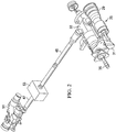
- Figure 2 illustrates a portion of the system
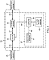
- Figure 3 schematically illustrates the system.
- aircraft 11 comprises fuselage 13 wing 15, and tail section 17.
- An electronic flight-control system 19 is shown located in fuselage 13.
- Nacelles 21, 23 are each pivotally mounted on opposing sides of fuselage 13 and, in this embodiment, on opposing ends of wing 15.
- Nacelle 21 houses propulsion assembly 25, and nacelle 23 houses propulsion assembly 27, each propulsion assembly 25, 27 comprising an engine 29, a gearbox 31, and a transmission 33.
- Gearbox 31 is configured for transferring torque from the associated engine 29 to a mast 35 for rotating an attached proprotor 39, each proprotor 39 being an assembly having multiple blades 41.
- Each mast 35 also transfers torque to the associated transmission 33.
- Each nacelle 21, 23 is pivotable relative to wing 15 for selectively moving propulsion assemblies 25, 27 and proprotors 39 between a vertical orientation in helicopter mode and a horizontal orientation in airplane mode.
- All propulsion assemblies according to this disclosure may alternatively be configured with electric motors to produce torque for driving proprotors 39, and electric versions may eliminate some components, such as, for example, gearbox 31.
- Transmissions 33 are operably connected to each other by an interconnect driveline 43, comprising driveshafts 45, 47, 49, mid-wing gearbox 51, and clutch 53.
- Interconnect driveline 43 is configured to transmit engine torque from transmission 33 of one of propulsion assemblies 25, 27 to transmission 33 of the other propulsion assembly 25, 27, allowing one engine 29 to drive both proprotors 39 for continued flight during one-engine inoperative conditions.
- Torque transmitted by driveline 43 through mid-wing gearbox 51 also supplies power to operate auxiliary systems.
- clutch 53 is positioned between driveshaft 45 and driveshaft 47 for operably coupling propulsion assembly 25 to mid-wing gearbox 51, although clutch 53 could alternatively be positioned in driveline 43 between propulsion assembly 27 and mid-wing gearbox 51.
- interconnect driveline 43 directly couples proprotors 39 for maintaining a selected phasing of proprotors 39 relative to each other.
- clutch 53 may be used to asymmetrically index, or "phase,” proprotors 39 for minimizing vibrations during operation of propulsion assemblies 25, 27.
- proprotors 39 may be phased relative to each other to an asymmetric, out-of-phase positioning or returned to symmetric, in-phase positioning.
- transient torque may be experienced from one proprotor 39 to the other proprotor 39 due to certain maneuvers, such as, for example, turns. These maneuvers can cause forces on proprotors 39 that would cause one proprotor 39 to rotate faster than the other proprotor 39, but this is prevented by proprotors 39 being connected to each other by interconnect driveline 43 and forced to turn at a synchronous rotational speed.
- proprotors 39 being connected to each other by interconnect driveline 43 and forced to turn at a synchronous rotational speed.
- a torque imbalance exists within driveline 43 between assemblies 25, 27, and significant torsional loads can be imparted on proprotors 39, mast 35, transmissions 33, and interconnect driveline 43, including spring-like torsional reactions in driveline 43.
- interconnect drive systems are configured to reduce the load and torque experienced by interconnect drivelines, allowing the components to be designed for lower torsional load levels.
- Drive system 55 couples propulsion assemblies 25, 27 and comprises driveline 43 and a clutch control system 57.
- driveline 43 operably couples transmissions 33 of propulsion assemblies 25, 27 through driveshafts 45, 47, 49, mid-wing gearbox 51, and clutch 53.
- Clutch 53 is a selectively engaged coupling between driveshafts 45 and 47, with clutch coupling driveshafts 45, 47 when engaged.
- All clutches in this disclosure can be one or a combination of several types, such as, for example, non-slip friction clutches (with dry or wet friction materials), slipper friction clutches, and positive engagement clutches (with interlocking components when engaged).
- Clutches according to this disclosure may also include a ratchet system.
- clutch 53 may be a dry, slipper friction clutch that, while engaged and capable of continuously transferring torque, passively allows for a limited amount of slipping to occur between driveshafts 45, 47 when a selected transient torque load is exceeded. All clutches of this disclosure are preferably configured to fail to engagement (i.e., remain engaged after failure or move to engagement after failure), ensuring that the propulsion assemblies remain coupled together for providing proper phasing and continued flight.
- Clutch control system 57 is an electronic system for operating clutch 53 in response to measured or calculated transient torque values.
- system 57 comprises at least an electronic computer 59, torque/load sensors 61, and attitude/motion sensors 63.
- Data connection 65 provides for data transmission between sensors 61 and computer 59 and data connection 67 provides for data transmission between sensors 63 and computer 59, data connections 65, 67 allowing for measured values to be communicated to computer 59 and for computer 59 to operate sensors 61, 63.
- Data connection 69 provides for data transmission between computer 59 and clutch 53 of driveline 43, allowing computer 59 to send commands for operation of clutch 53 and to receive data communications from clutch 53. All data connections according to this disclosure can be wired or wireless.
- Computer 59 may be a standalone device or may be an integral component of flight control system 19 ( Figure 1 ).
- Torque/load sensors 61 may be, for example, strain gauges affixed to one or more of driveshafts 45, 47, 49 or torque sensor components installed between components of driveline 43.
- Attitude/motion sensors 63 may be, for example, one or more of a combination of gyroscopes, accelerometers, inertial guidance components, or similar devices for determining the attitude and motion of aircraft 11.
- each propulsion assembly 25, 27 produces torque that is transferred to the associated mast 35 through gearbox 31. This torque is also transferred from transmission 33 of assembly 25 into driveshaft 45 and from transmission 33 of assembly 27 into driveshaft 49.
- the torque output in driveshafts 45, 49 is substantially balanced and proprotors 39 are continuously symmetrically indexed, at 0 degrees blade offset, or continuously phased relative to each other, for example, at 60 degrees out-of-phase.
- proprotors 39 experiences a transient torque that would cause that proprotor 39 to turn faster, that torque is transferred through driveline 43 to the other proprotor 39 and would cause the other proprotor 39 to also turn faster.
- clutch 53 permits faster rotation of one of proprotors 39 relative to the other proprotor 39 to lessen the transient torque transmitted through driveline 43. This is accomplished by allowing driveshafts 45, 47, which normally rotate at the same speed, to rotate relative to each other about their axis of rotation as driveshafts 45, 47 continue to rotate. As driveshaft 47 is coupled to driveshaft 49 through mid-wing gearbox 51, this allows for rotation of driveshafts 45, 49 relative to each other and phasing of proprotors 39.
- This relative rotation occurs at clutch 53 by allowing a "break" in driveline 43, and this may occur as limited, passive slippage between friction components or through active disengagement of clutch 53 as commanded by computer 59.
- "disengagement” is a separation of coupling components within clutch 53 or allowing slippage by reducing the pressure applied to friction components within clutch 53.
- the allowed amount of relative rotation of driveshafts 45, 47 will be based on the amount and duration of the transient torque, and this is unlike the predetermined relative rotation of driveshafts 45, 47 when using clutch 53 to phase proprotors 39 by a selected angle solely for vibration attenuation, as described in US 14/174,004 .
- clutch 53 will be commanded by computer 59 to disengage to cause a break in driveline 43 until proprotors 39 re-index to the desired phasing.
- the current rotational position and rotational speed of each proprotor 39 will be communicated to computer 59 from position sensors (not shown) for each proprotor 39 or each mast 35, allowing computer 59 to calculate the required duration of the disengagement of clutch 53 and providing a feedback loop for phase adjustment.
- a ratcheting mechanism may be used in clutch 53 to allow relative rotation of driveshafts 45, 47 in only one direction.
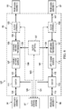
- FIG. 4 is a schematic illustration of an alternative embodiment of an interconnect drive system according to this disclosure.
- System 71 is configured for use with aircraft 11 for coupling propulsion assemblies 25, 27.
- System 71 is similar to system 55, as shown and described above, and comprises an interconnect driveline 73 and clutch control system 57.
- Driveline 75 comprises the components of driveline 43, with the exception of driveshaft 49 being replaced by a second clutch 75 and driveshafts 77, 79 that operably couple propulsion assembly 27 to mid-wing gearbox 51.
- Driveshaft 77 couples clutch 75 to gearbox 51, and driveshaft 79 couples clutch 75 to transmission 33 (not shown) of propulsion assembly 27.
- a wired or wireless data connection 81 provides for data transmission between computer 59 and clutch 75, and data connections 69, 81 allow computer 59 to communicate commands for operation of clutches 53, 75 and to receive data communications from clutch 53, 75.
- clutches 53, 75 may passively slip or be commanded to disengage in response to a transient torque on one of proprotors 39, as measured by torque/load sensors 61, or a transient torque-causing event, as calculated by computer 59 based on data from attitude/motion sensors 63.
- clutches 53,75 can be disengaged to permit faster rotation of one of proprotors 39 relative to the other proprotor 39 for lessening the transient torque transmitted through driveline 73. This is accomplished by allowing driveshafts 45, 47 to rotate relative to each other and/or allowing driveshafts 77, 79 to rotate relative to each other in the manner described above. Clutches 53, 75 are preferably disengaged one at a time, which is all that is required to create a break in driveline 73. Though clutches 53, 75 may be disengaged simultaneously, it is preferred that at least a slip coupling is maintained in at least one clutch 53, 75 to provide for torque to be continuously transferred to mid-wing gearbox 51.
- Clutches 53, 75 may be operated in an equal or unequal alternating basis, though one of clutches 53, 75 may be designated as primary and the other clutch 53, 75 designated as backup, with the primary clutch 53, 75 being used exclusively until specified operating conditions are exceeded (e.g., excessive heat buildup), routine maintenance is required, or disengagement components fail. As noted above, clutches 53, 75 are configured to fail to engagement.
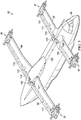
- FIGs 5 and 7 illustrate tiltrotor aircraft, each comprising an alternative embodiment of an interconnect drive system according to this disclosure.
- the systems are shown schematically for these aircraft, respectively, in Figures 6 and 8 .
- a quad-tiltrotor aircraft 83 comprises fuselage 85, forward wing 87, and aft wing 89.
- Propulsion assemblies 91, 93 are pivotally mounted at opposing ends of forward wing 87
- propulsion assemblies 95, 97 are pivotally mounted at opposing ends of aft wing 89, each propulsion assembly 91, 93, 95, 97 having similar components as, and being configured similarly to, propulsion assemblies 25, 27 of aircraft 11.
- propulsion assemblies 91, 93, 95, 97 are each configured for driving an attached proprotor (not shown) in rotation.
- An interconnect driveline 99 operably couples transmissions of propulsion assemblies 91, 93, 95, 97 for allowing torque transfer between assemblies 91, 93, 95, 97 and for maintaining a selected relative phasing of the proprotors of aircraft 83.
- a forward portion of driveline 99 is located within wing 87 and comprises driveshafts 101, 103, 105, mid-wing gearbox 107, mid- wing transmission 109, and clutch 111.
- Driveshaft 101 couples propulsion assembly 91 to clutch 111
- driveshaft 103 couples clutch 111 to gearbox 107 (which is directly coupled to transmission 109)
- driveshaft 105 couples propulsion assembly 93 to transmission 109.
- An aft portion of driveline 99 is located within wing 89 and comprises driveshafts 113, 115, 117, mid-wing gearbox 119, mid-wing transmission 121, and clutch 123.
- Driveshaft 113 couples propulsion assembly 95 to clutch 123
- driveshaft 115 couples clutch 123 to gearbox 119 (which is directly coupled to transmission 121)
- driveshaft 117 couples propulsion assembly 97 to transmission 121.
- a driveshaft 125 extends longitudinally between wings 87, 89 and couples transmissions 109, 121, thereby providing a torque path from each of propulsion assemblies 91, 93, 95, 97 to all other assemblies 91, 93, 95, 97.
- interconnect driveline 99 can be modified for use with aircraft having additional wings and/or propulsion assemblies.
- FIG. 6 is a schematic illustration of interconnect drive system 127, comprising interconnect driveline 99 and clutch control system 57 (as shown and described above for systems 55, 71).
- a wired or wireless data connection 129 provides for data transmission between computer 59 (not shown) of system 57 and clutch 111
- wired or wireless data connection 131 provides for data transmission between computer 59 and clutch 123.
- data connections 129, 131 allow computer 59 to communicate commands for operation of clutches 111, 123 and to receive data communications from clutch 111, 123.
- clutches 111, 123 may passively slip or be commanded to disengage in response to transient torque on one of the proprotors of aircraft 83, as measured by torque/load sensors 61, or to a maneuver calculated, based on data from attitude/motion sensors 63, by computer 59 to cause a transient torque imbalance.
- Clutch 111 allows for the proprotor of one of propulsion assemblies 91, 93 to rotate faster than the proprotor of the other propulsion assembly 91, 93 by allowing driveshafts 101, 103 to rotate relative to each other in the manner described above.
- Clutch 123 allows for the proprotor of one of propulsion assemblies 95, 97 to rotate faster than the proprotor of the other propulsion assembly 95, 97 by allowing driveshafts 113, 115 to rotate relative to each other in the manner described above. It should be noted that this configuration does not provide for a break in the torque path between propulsion assemblies 93, 97, though assemblies 93, 97 will likely encounter similar transienttoque events due to being on the same side of aircraft 83. Clutches 111, 123 may be disengaged simultaneously, as propulsion assemblies 93, 97 are always coupled to mid-wing gearboxes 107, 119.
- optional components include additional forward clutch 133 coupling propulsion assembly 93 to mid-wing transmission 109, additional aft clutch 135 coupling propulsion assembly 97 to mid- wing transmission 121, and central clutch 137 coupling transmissions 109, 121 to each other.
- Optional data connections 139, 141, 143 are used to provide data communication between computer 59 and clutches 133, 135, 137, respectively.
- Clutches 111, 123, 133, 135, 137 may be operated separately or in any combination to achieve the result of driving proprotors associated with propulsion systems 91, 93, 95, 97 while allowing for phasing of the proprotors to alleviate loads in driveline 99 caused by transient torque experienced by the proprotors during flight.
- a tiltrotor aircraft 145 comprises fuselage 147, wing 149, and tail section 151.
- Propulsion assemblies 152, 153 are mounted at opposing ends of wing 149, each assembly 152, 153 comprising similar components to propulsion assemblies 25, 27 of aircraft 11 and described above.
- the engine and gearbox (not visible) of each assembly 152, 153 are carried in a fixed nacelle 155, 157, with only an associated mast (not visible) and attached proprotor 159 pivoting together on an associated pylon 161, 163 relative to wing 149.
- a pusher propeller 165 is mounted at the aft end of fuselage 147 for providing additional longitudinal thrust.
- an interconnect drive system 167 comprises interconnect driveline 169 and clutch control system 57 (as shown and described above for systems 55, 71, 127).
- Driveline 169 operably couples the transmissions of propulsion assemblies 152, 153 for allowing torque transfer between assemblies 152, 153 and propeller 165 and also for maintaining a selected relative phasing of proprotors 159.
- Driveline 169 comprises driveshafts 171, 173, 175, 177, mid-wing gearbox 179, mid-wing transmission 181, and clutch 183.
- Driveshaft 171 couples propulsion assembly 152 to clutch 183, driveshaft 173 couples clutch 183 to gearbox 179 (which is directly coupled to transmission 181), and driveshaft 175 couples propulsion assembly 153 to transmission 181.
- Driveshaft 177 extends longitudinally and couples mid-wing transmission 181 to propeller 165, thereby providing a torque path from each one of propulsion assemblies 152, 153 to the other assembly 152, 153 and to propeller 165.
- a wired or wireless data connection 185 provides for data transmission between computer 59 (not shown) of system 57 and clutch 183. As described above for systems 55, 71, 127, data connection 185 allows computer 59 to communicate commands for operation of clutches 183 and to receive data communications from clutch 183. As shown in broken lines in the figure, optional components include additional forward clutch 187 coupling propulsion assembly 153 to mid-wing transmission 181 and central clutch 189 coupling transmissions 181 to propeller 165. Optional data connections 191, 193 are used to provide data communication between computer 59 and clutches 187, 189, respectively.
- Clutches 183, 187, 189 may be operated separately or in any combination to achieve the result of driving proprotors of propulsion assemblies 152, 153 while allowing for phasing of the proprotors to alleviate an imbalance of torque loads in driveline 169 caused by transient torque experienced by the proprotors during flight.
- one or more clutches may be incorporated into a mid- wing gearbox, a mid-wing transmission, or a transmission of a propulsion assembly.
- R R1 +k* (Ru-Rl), wherein k is a variable ranging from 1 percent to 100 percent with a 1 percent increment, i.e., k is 1 percent, 2 percent, 3 percent, 4 percent, 5 percent,...50 percent, 51 percent, 52 percent,..., 95 percent, 96 percent, 97 percent, 98 percent, 99 percent, or 100 percent.
- R R1 +k* (Ru-Rl)
- k is a variable ranging from 1 percent to 100 percent with a 1 percent increment, i.e., k is 1 percent, 2 percent, 3 percent, 4 percent, 5 percent,...50 percent, 51 percent, 52 percent,..., 95 percent, 96 percent, 97 percent, 98 percent, 99 percent, or 100 percent.
- any numerical range defined by two R numbers as defined in the above is also specifically disclosed.
Landscapes
- Engineering & Computer Science (AREA)
- Aviation & Aerospace Engineering (AREA)
- Mechanical Engineering (AREA)
- Tires In General (AREA)
Applications Claiming Priority (1)
| Application Number | Priority Date | Filing Date | Title |
|---|---|---|---|
| US15/495,762 US10384765B2 (en) | 2014-02-06 | 2017-04-24 | Interconnect drive system |
Publications (2)
| Publication Number | Publication Date |
|---|---|
| EP3395680A1 true EP3395680A1 (de) | 2018-10-31 |
| EP3395680B1 EP3395680B1 (de) | 2019-08-07 |
Family
ID=60569736
Family Applications (1)
| Application Number | Title | Priority Date | Filing Date |
|---|---|---|---|
| EP17204970.2A Active EP3395680B1 (de) | 2017-04-24 | 2017-12-01 | Verbindendes antriebssystem |
Country Status (1)
| Country | Link |
|---|---|
| EP (1) | EP3395680B1 (de) |
Cited By (2)
| Publication number | Priority date | Publication date | Assignee | Title |
|---|---|---|---|---|
| CN112591111A (zh) * | 2019-10-02 | 2021-04-02 | 波音公司 | 具有交叉连接离合器的用于飞机的双混合推进系统 |
| WO2022194669A1 (de) * | 2021-03-15 | 2022-09-22 | Zf Friedrichshafen Ag | Luftfahrtantriebssystem eines fluggerätes |
Families Citing this family (2)
| Publication number | Priority date | Publication date | Assignee | Title |
|---|---|---|---|---|
| JP7543457B2 (ja) * | 2023-01-13 | 2024-09-02 | ナブテスコ株式会社 | 飛行体、モータ制御装置、方法、及びプログラム |
| GB2638939A (en) * | 2023-11-20 | 2025-09-10 | Sora Aviation Ltd | Large vertical takeoff and landing aircraft |
Citations (5)
| Publication number | Priority date | Publication date | Assignee | Title |
|---|---|---|---|---|
| US2462824A (en) * | 1944-11-03 | 1949-02-22 | United Aircraft Corp | Single or multiengined drive for plural airscrews |
| US20070205321A1 (en) * | 2005-06-24 | 2007-09-06 | Karem Aircraft, Inc. | Speed changing gearbox with dual path input |
| DE102013209538A1 (de) * | 2013-05-23 | 2014-11-27 | Robert Bosch Gmbh | Hybridantrieb für kraftgetriebenes Luftfahrzeug, kraftgetriebenes Luftfahrzeug mit Hybridantrieb und zugehöriges Betriebsverfahren |
| EP2930398A1 (de) * | 2014-04-10 | 2015-10-14 | Bell Helicopter Textron Inc. | Stufenloses flugzeuggetriebe |
| US20160229531A1 (en) * | 2014-12-11 | 2016-08-11 | Bell Helicopter Textron Inc. | Convertible tiltrotor aircraft |
-
2017
- 2017-12-01 EP EP17204970.2A patent/EP3395680B1/de active Active
Patent Citations (5)
| Publication number | Priority date | Publication date | Assignee | Title |
|---|---|---|---|---|
| US2462824A (en) * | 1944-11-03 | 1949-02-22 | United Aircraft Corp | Single or multiengined drive for plural airscrews |
| US20070205321A1 (en) * | 2005-06-24 | 2007-09-06 | Karem Aircraft, Inc. | Speed changing gearbox with dual path input |
| DE102013209538A1 (de) * | 2013-05-23 | 2014-11-27 | Robert Bosch Gmbh | Hybridantrieb für kraftgetriebenes Luftfahrzeug, kraftgetriebenes Luftfahrzeug mit Hybridantrieb und zugehöriges Betriebsverfahren |
| EP2930398A1 (de) * | 2014-04-10 | 2015-10-14 | Bell Helicopter Textron Inc. | Stufenloses flugzeuggetriebe |
| US20160229531A1 (en) * | 2014-12-11 | 2016-08-11 | Bell Helicopter Textron Inc. | Convertible tiltrotor aircraft |
Cited By (6)
| Publication number | Priority date | Publication date | Assignee | Title |
|---|---|---|---|---|
| CN112591111A (zh) * | 2019-10-02 | 2021-04-02 | 波音公司 | 具有交叉连接离合器的用于飞机的双混合推进系统 |
| EP3800125A1 (de) * | 2019-10-02 | 2021-04-07 | The Boeing Company | Doppel-hybridantriebssystem für ein flugzeug mit einer kreuzkupplung |
| US11286054B2 (en) | 2019-10-02 | 2022-03-29 | The Boeing Company | Dual hybrid propulsion system for an aircraft having a cross-connecting clutch |
| CN112591111B (zh) * | 2019-10-02 | 2025-03-18 | 波音公司 | 具有交叉连接离合器的用于飞机的双混合推进系统 |
| WO2022194669A1 (de) * | 2021-03-15 | 2022-09-22 | Zf Friedrichshafen Ag | Luftfahrtantriebssystem eines fluggerätes |
| US12509239B2 (en) | 2021-03-15 | 2025-12-30 | Airbus Helicopters Technik Gmbh | Aviation propulsion system for an aircraft with rotatable shafts having mutually facing ends connected via shaft coupling, gearbox unit and overload protection element |
Also Published As
| Publication number | Publication date |
|---|---|
| EP3395680B1 (de) | 2019-08-07 |
Similar Documents
| Publication | Publication Date | Title |
|---|---|---|
| US10384765B2 (en) | Interconnect drive system | |
| EP3395680B1 (de) | Verbindendes antriebssystem | |
| US5226350A (en) | Drive train assembly for a rotor assembly having ducted, coaxial counter-rotating rotors | |
| EP3428065B1 (de) | Regelantriebssystem für kipprotor mit festem motor und rotierendem proprotor | |
| US20100276549A1 (en) | Fail-operational multiple lifting-rotor aircraft | |
| EP0861776B1 (de) | Antriebsstranganordnung für unbemanntes Fluggerät | |
| US20190193836A1 (en) | High Stiffness Hub Assemblies for Rotor Systems | |
| US20210347472A1 (en) | Fail-operational vtol aircraft | |
| US5340279A (en) | Snubber assembly for a rotor assembly having ducted, coaxial counter-rotating rotors | |
| RU2472675C2 (ru) | Приводное устройство, предназначенное для приведения в действие первого и второго подъемных несущих винтов винтокрылого летательного аппарата, имеющего последовательные спаренные несущие винты | |
| US20090224096A1 (en) | Rotorcraft engine and rotor speed synchronization | |
| EP1971521B1 (de) | Schwenksteife kardanische kipprotornabe | |
| EP2778062A1 (de) | Kardanisch gelagerte Heckrotornabe mit sphärisch-elastischem Zentrifugalkraftlager für Rotorblattrückhaltung und Anstellwinkeländerung | |
| US9476312B2 (en) | Swashplateless active blade pitch control with a mechanical delta-3 restraint having an instantaneous blade pitch-flap coupling response | |
| EP2657130B1 (de) | Flugzeugrotor mit diskreten Schlaggelenken | |
| EP3446973B1 (de) | Anpassbares rotorregelungssystem für eine variable anzahl von schaufeln | |
| US5281099A (en) | Integrated spline/cone seat subassembly for a rotor assembly having ducted, coaxial counter-rotating rotors | |
| EP2722277B1 (de) | Direktantriebssteuerung einer Flugzeugstabilitätserhöhung | |
| US11952111B2 (en) | Electronic control of blade pitch on a tiltrotor | |
| EP3737609A1 (de) | Übertragungssystem für flugzeugstruktur | |
| EP4101755B1 (de) | Zusätzliche motorleistungssteuerung | |
| EP2894095B1 (de) | Kupplung für konstante Geschwindigkeit für Kipprotoranordnung | |
| EP2778058B1 (de) | Mehrgliedriges Gleichlaufgelenk | |
| US10843789B2 (en) | Selectively engageable aircraft driveshaft using friction plates | |
| CN113226924B (zh) | 飞行器 |
Legal Events
| Date | Code | Title | Description |
|---|---|---|---|
| STAA | Information on the status of an ep patent application or granted ep patent |
Free format text: STATUS: EXAMINATION IS IN PROGRESS |
|
| PUAI | Public reference made under article 153(3) epc to a published international application that has entered the european phase |
Free format text: ORIGINAL CODE: 0009012 |
|
| 17P | Request for examination filed |
Effective date: 20171201 |
|
| AK | Designated contracting states |
Kind code of ref document: A1 Designated state(s): AL AT BE BG CH CY CZ DE DK EE ES FI FR GB GR HR HU IE IS IT LI LT LU LV MC MK MT NL NO PL PT RO RS SE SI SK SM TR |
|
| AX | Request for extension of the european patent |
Extension state: BA ME |
|
| GRAP | Despatch of communication of intention to grant a patent |
Free format text: ORIGINAL CODE: EPIDOSNIGR1 |
|
| STAA | Information on the status of an ep patent application or granted ep patent |
Free format text: STATUS: GRANT OF PATENT IS INTENDED |
|
| INTG | Intention to grant announced |
Effective date: 20190205 |
|
| GRAS | Grant fee paid |
Free format text: ORIGINAL CODE: EPIDOSNIGR3 |
|
| GRAJ | Information related to disapproval of communication of intention to grant by the applicant or resumption of examination proceedings by the epo deleted |
Free format text: ORIGINAL CODE: EPIDOSDIGR1 |
|
| GRAL | Information related to payment of fee for publishing/printing deleted |
Free format text: ORIGINAL CODE: EPIDOSDIGR3 |
|
| STAA | Information on the status of an ep patent application or granted ep patent |
Free format text: STATUS: EXAMINATION IS IN PROGRESS |
|
| GRAR | Information related to intention to grant a patent recorded |
Free format text: ORIGINAL CODE: EPIDOSNIGR71 |
|
| STAA | Information on the status of an ep patent application or granted ep patent |
Free format text: STATUS: GRANT OF PATENT IS INTENDED |
|
| GRAA | (expected) grant |
Free format text: ORIGINAL CODE: 0009210 |
|
| STAA | Information on the status of an ep patent application or granted ep patent |
Free format text: STATUS: THE PATENT HAS BEEN GRANTED |
|
| INTC | Intention to grant announced (deleted) | ||
| AK | Designated contracting states |
Kind code of ref document: B1 Designated state(s): AL AT BE BG CH CY CZ DE DK EE ES FI FR GB GR HR HU IE IS IT LI LT LU LV MC MK MT NL NO PL PT RO RS SE SI SK SM TR |
|
| INTG | Intention to grant announced |
Effective date: 20190702 |
|
| REG | Reference to a national code |
Ref country code: GB Ref legal event code: FG4D |
|
| REG | Reference to a national code |
Ref country code: CH Ref legal event code: EP Ref country code: AT Ref legal event code: REF Ref document number: 1163452 Country of ref document: AT Kind code of ref document: T Effective date: 20190815 |
|
| REG | Reference to a national code |
Ref country code: IE Ref legal event code: FG4D |
|
| REG | Reference to a national code |
Ref country code: DE Ref legal event code: R096 Ref document number: 602017005936 Country of ref document: DE |
|
| REG | Reference to a national code |
Ref country code: NL Ref legal event code: MP Effective date: 20190807 |
|
| REG | Reference to a national code |
Ref country code: LT Ref legal event code: MG4D |
|
| PG25 | Lapsed in a contracting state [announced via postgrant information from national office to epo] |
Ref country code: BG Free format text: LAPSE BECAUSE OF FAILURE TO SUBMIT A TRANSLATION OF THE DESCRIPTION OR TO PAY THE FEE WITHIN THE PRESCRIBED TIME-LIMIT Effective date: 20191107 Ref country code: NL Free format text: LAPSE BECAUSE OF FAILURE TO SUBMIT A TRANSLATION OF THE DESCRIPTION OR TO PAY THE FEE WITHIN THE PRESCRIBED TIME-LIMIT Effective date: 20190807 Ref country code: NO Free format text: LAPSE BECAUSE OF FAILURE TO SUBMIT A TRANSLATION OF THE DESCRIPTION OR TO PAY THE FEE WITHIN THE PRESCRIBED TIME-LIMIT Effective date: 20191107 Ref country code: SE Free format text: LAPSE BECAUSE OF FAILURE TO SUBMIT A TRANSLATION OF THE DESCRIPTION OR TO PAY THE FEE WITHIN THE PRESCRIBED TIME-LIMIT Effective date: 20190807 Ref country code: LT Free format text: LAPSE BECAUSE OF FAILURE TO SUBMIT A TRANSLATION OF THE DESCRIPTION OR TO PAY THE FEE WITHIN THE PRESCRIBED TIME-LIMIT Effective date: 20190807 Ref country code: HR Free format text: LAPSE BECAUSE OF FAILURE TO SUBMIT A TRANSLATION OF THE DESCRIPTION OR TO PAY THE FEE WITHIN THE PRESCRIBED TIME-LIMIT Effective date: 20190807 Ref country code: PT Free format text: LAPSE BECAUSE OF FAILURE TO SUBMIT A TRANSLATION OF THE DESCRIPTION OR TO PAY THE FEE WITHIN THE PRESCRIBED TIME-LIMIT Effective date: 20191209 Ref country code: FI Free format text: LAPSE BECAUSE OF FAILURE TO SUBMIT A TRANSLATION OF THE DESCRIPTION OR TO PAY THE FEE WITHIN THE PRESCRIBED TIME-LIMIT Effective date: 20190807 |
|
| REG | Reference to a national code |
Ref country code: AT Ref legal event code: MK05 Ref document number: 1163452 Country of ref document: AT Kind code of ref document: T Effective date: 20190807 |
|
| PG25 | Lapsed in a contracting state [announced via postgrant information from national office to epo] |
Ref country code: LV Free format text: LAPSE BECAUSE OF FAILURE TO SUBMIT A TRANSLATION OF THE DESCRIPTION OR TO PAY THE FEE WITHIN THE PRESCRIBED TIME-LIMIT Effective date: 20190807 Ref country code: ES Free format text: LAPSE BECAUSE OF FAILURE TO SUBMIT A TRANSLATION OF THE DESCRIPTION OR TO PAY THE FEE WITHIN THE PRESCRIBED TIME-LIMIT Effective date: 20190807 Ref country code: AL Free format text: LAPSE BECAUSE OF FAILURE TO SUBMIT A TRANSLATION OF THE DESCRIPTION OR TO PAY THE FEE WITHIN THE PRESCRIBED TIME-LIMIT Effective date: 20190807 Ref country code: IS Free format text: LAPSE BECAUSE OF FAILURE TO SUBMIT A TRANSLATION OF THE DESCRIPTION OR TO PAY THE FEE WITHIN THE PRESCRIBED TIME-LIMIT Effective date: 20191207 Ref country code: GR Free format text: LAPSE BECAUSE OF FAILURE TO SUBMIT A TRANSLATION OF THE DESCRIPTION OR TO PAY THE FEE WITHIN THE PRESCRIBED TIME-LIMIT Effective date: 20191108 Ref country code: RS Free format text: LAPSE BECAUSE OF FAILURE TO SUBMIT A TRANSLATION OF THE DESCRIPTION OR TO PAY THE FEE WITHIN THE PRESCRIBED TIME-LIMIT Effective date: 20190807 |
|
| PG25 | Lapsed in a contracting state [announced via postgrant information from national office to epo] |
Ref country code: TR Free format text: LAPSE BECAUSE OF FAILURE TO SUBMIT A TRANSLATION OF THE DESCRIPTION OR TO PAY THE FEE WITHIN THE PRESCRIBED TIME-LIMIT Effective date: 20190807 |
|
| PG25 | Lapsed in a contracting state [announced via postgrant information from national office to epo] |
Ref country code: AT Free format text: LAPSE BECAUSE OF FAILURE TO SUBMIT A TRANSLATION OF THE DESCRIPTION OR TO PAY THE FEE WITHIN THE PRESCRIBED TIME-LIMIT Effective date: 20190807 Ref country code: RO Free format text: LAPSE BECAUSE OF FAILURE TO SUBMIT A TRANSLATION OF THE DESCRIPTION OR TO PAY THE FEE WITHIN THE PRESCRIBED TIME-LIMIT Effective date: 20190807 Ref country code: EE Free format text: LAPSE BECAUSE OF FAILURE TO SUBMIT A TRANSLATION OF THE DESCRIPTION OR TO PAY THE FEE WITHIN THE PRESCRIBED TIME-LIMIT Effective date: 20190807 Ref country code: PL Free format text: LAPSE BECAUSE OF FAILURE TO SUBMIT A TRANSLATION OF THE DESCRIPTION OR TO PAY THE FEE WITHIN THE PRESCRIBED TIME-LIMIT Effective date: 20190807 Ref country code: DK Free format text: LAPSE BECAUSE OF FAILURE TO SUBMIT A TRANSLATION OF THE DESCRIPTION OR TO PAY THE FEE WITHIN THE PRESCRIBED TIME-LIMIT Effective date: 20190807 |
|
| PG25 | Lapsed in a contracting state [announced via postgrant information from national office to epo] |
Ref country code: IS Free format text: LAPSE BECAUSE OF FAILURE TO SUBMIT A TRANSLATION OF THE DESCRIPTION OR TO PAY THE FEE WITHIN THE PRESCRIBED TIME-LIMIT Effective date: 20200224 Ref country code: SM Free format text: LAPSE BECAUSE OF FAILURE TO SUBMIT A TRANSLATION OF THE DESCRIPTION OR TO PAY THE FEE WITHIN THE PRESCRIBED TIME-LIMIT Effective date: 20190807 Ref country code: CZ Free format text: LAPSE BECAUSE OF FAILURE TO SUBMIT A TRANSLATION OF THE DESCRIPTION OR TO PAY THE FEE WITHIN THE PRESCRIBED TIME-LIMIT Effective date: 20190807 Ref country code: SK Free format text: LAPSE BECAUSE OF FAILURE TO SUBMIT A TRANSLATION OF THE DESCRIPTION OR TO PAY THE FEE WITHIN THE PRESCRIBED TIME-LIMIT Effective date: 20190807 |
|
| REG | Reference to a national code |
Ref country code: DE Ref legal event code: R097 Ref document number: 602017005936 Country of ref document: DE |
|
| PLBE | No opposition filed within time limit |
Free format text: ORIGINAL CODE: 0009261 |
|
| STAA | Information on the status of an ep patent application or granted ep patent |
Free format text: STATUS: NO OPPOSITION FILED WITHIN TIME LIMIT |
|
| PG2D | Information on lapse in contracting state deleted |
Ref country code: IS |
|
| 26N | No opposition filed |
Effective date: 20200603 |
|
| REG | Reference to a national code |
Ref country code: BE Ref legal event code: MM Effective date: 20191231 |
|
| PG25 | Lapsed in a contracting state [announced via postgrant information from national office to epo] |
Ref country code: MC Free format text: LAPSE BECAUSE OF FAILURE TO SUBMIT A TRANSLATION OF THE DESCRIPTION OR TO PAY THE FEE WITHIN THE PRESCRIBED TIME-LIMIT Effective date: 20190807 |
|
| PG25 | Lapsed in a contracting state [announced via postgrant information from national office to epo] |
Ref country code: LU Free format text: LAPSE BECAUSE OF NON-PAYMENT OF DUE FEES Effective date: 20191201 Ref country code: IE Free format text: LAPSE BECAUSE OF NON-PAYMENT OF DUE FEES Effective date: 20191201 |
|
| PG25 | Lapsed in a contracting state [announced via postgrant information from national office to epo] |
Ref country code: BE Free format text: LAPSE BECAUSE OF NON-PAYMENT OF DUE FEES Effective date: 20191231 |
|
| PG25 | Lapsed in a contracting state [announced via postgrant information from national office to epo] |
Ref country code: CY Free format text: LAPSE BECAUSE OF FAILURE TO SUBMIT A TRANSLATION OF THE DESCRIPTION OR TO PAY THE FEE WITHIN THE PRESCRIBED TIME-LIMIT Effective date: 20190807 |
|
| PG25 | Lapsed in a contracting state [announced via postgrant information from national office to epo] |
Ref country code: HU Free format text: LAPSE BECAUSE OF FAILURE TO SUBMIT A TRANSLATION OF THE DESCRIPTION OR TO PAY THE FEE WITHIN THE PRESCRIBED TIME-LIMIT; INVALID AB INITIO Effective date: 20171201 Ref country code: MT Free format text: LAPSE BECAUSE OF FAILURE TO SUBMIT A TRANSLATION OF THE DESCRIPTION OR TO PAY THE FEE WITHIN THE PRESCRIBED TIME-LIMIT Effective date: 20190807 |
|
| REG | Reference to a national code |
Ref country code: CH Ref legal event code: PL |
|
| PG25 | Lapsed in a contracting state [announced via postgrant information from national office to epo] |
Ref country code: SI Free format text: LAPSE BECAUSE OF FAILURE TO SUBMIT A TRANSLATION OF THE DESCRIPTION OR TO PAY THE FEE WITHIN THE PRESCRIBED TIME-LIMIT Effective date: 20190807 |
|
| PG25 | Lapsed in a contracting state [announced via postgrant information from national office to epo] |
Ref country code: LI Free format text: LAPSE BECAUSE OF NON-PAYMENT OF DUE FEES Effective date: 20201231 Ref country code: CH Free format text: LAPSE BECAUSE OF NON-PAYMENT OF DUE FEES Effective date: 20201231 |
|
| PG25 | Lapsed in a contracting state [announced via postgrant information from national office to epo] |
Ref country code: MK Free format text: LAPSE BECAUSE OF FAILURE TO SUBMIT A TRANSLATION OF THE DESCRIPTION OR TO PAY THE FEE WITHIN THE PRESCRIBED TIME-LIMIT Effective date: 20190807 |
|
| P01 | Opt-out of the competence of the unified patent court (upc) registered |
Effective date: 20230602 |
|
| PGFP | Annual fee paid to national office [announced via postgrant information from national office to epo] |
Ref country code: GB Payment date: 20251229 Year of fee payment: 9 |
|
| PGFP | Annual fee paid to national office [announced via postgrant information from national office to epo] |
Ref country code: IT Payment date: 20251219 Year of fee payment: 9 |
|
| PGFP | Annual fee paid to national office [announced via postgrant information from national office to epo] |
Ref country code: FR Payment date: 20251226 Year of fee payment: 9 |
|
| PGFP | Annual fee paid to national office [announced via postgrant information from national office to epo] |
Ref country code: DE Payment date: 20251229 Year of fee payment: 9 |