EP3395499A1 - Machine-tool seal member - Google Patents
Machine-tool seal member Download PDFInfo
- Publication number
- EP3395499A1 EP3395499A1 EP16878173.0A EP16878173A EP3395499A1 EP 3395499 A1 EP3395499 A1 EP 3395499A1 EP 16878173 A EP16878173 A EP 16878173A EP 3395499 A1 EP3395499 A1 EP 3395499A1
- Authority
- EP
- European Patent Office
- Prior art keywords
- machine tools
- sealing member
- elastic member
- support
- machine
- Prior art date
- Legal status (The legal status is an assumption and is not a legal conclusion. Google has not performed a legal analysis and makes no representation as to the accuracy of the status listed.)
- Granted
Links
Images





Classifications
-
- B—PERFORMING OPERATIONS; TRANSPORTING
- B23—MACHINE TOOLS; METAL-WORKING NOT OTHERWISE PROVIDED FOR
- B23Q—DETAILS, COMPONENTS, OR ACCESSORIES FOR MACHINE TOOLS, e.g. ARRANGEMENTS FOR COPYING OR CONTROLLING; MACHINE TOOLS IN GENERAL CHARACTERISED BY THE CONSTRUCTION OF PARTICULAR DETAILS OR COMPONENTS; COMBINATIONS OR ASSOCIATIONS OF METAL-WORKING MACHINES, NOT DIRECTED TO A PARTICULAR RESULT
- B23Q11/00—Accessories fitted to machine tools for keeping tools or parts of the machine in good working condition or for cooling work; Safety devices specially combined with or arranged in, or specially adapted for use in connection with, machine tools
- B23Q11/08—Protective coverings for parts of machine tools; Splash guards
- B23Q11/0875—Wipers for clearing foreign matter from slideways or slidable coverings
Definitions
- the present invention relates to a sealing member for machine tools.
- Machine tools such as a lathe and a machining center is the most basic machine device generally used in manufacturing industries.
- a sealing member for machine tools such as a lip seal, a slide seal, a telescopic seal, and a cover seal is used.
- Patent Literature 1 For example, a sealing member for machine tools (a wiper for machine tools) disclosed in Patent Literature 1 is known.
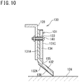
- Patent Literature 1 discloses a sealing member for machine tools (a wiper for machine tools) 130 shown in FIG. 10.
- FIG. 10 is a cross-sectional view illustrating one example of a conventional sealing member for machine tools.
- the wiper for machine tools 130 is formed in a plate shape.
- the wiper for machine tools 130 includes a mount portion 131 for mounting the wiper 130 to a machine tool, and a lip portion 132 formed in a plate shape and bent from the mount portion 131.
- the mount portion 131 is formed of a rubber body with a metal reinforcing plate 134 arranged on a front surface thereof.
- the rubber body is vulcanized and bonded to the reinforcing plate 134.
- the lip portion 132 is formed of rubber integrally with the rubber body of the mount portion 131.
- a groove 135 extended in a longitudinal direction (a penetration direction of a paper) and formed in an arc shape in cross section is formed at a side of the front surface of a connection portion between the mount portion 131 and the lip portion 132. Further, a plurality of screw holes 133 is formed on the mount portion 131.
- a metal plate 136 is arranged at a side of a rear surface 132A of the lip portion 132. A front surface of the metal plate 136 is stuck to the rear surface 132A of the lip portion 132 so as to be completely covered by the lip portion 132.
- the wiper 130 is mounted to a fixed cover 128 of the machine tool by inserting a screw 141 into the screw hole 133 of the mount portion 131.
- the mount portion 131 is mounted such that a vertical surface 131A is arranged along the fixed cover 128 so that the vertical surfaces 131A, 131C of the mount portion 131 are arranged orthogonal to a sliding surface 124 of the machine tool.
- the lip portion 132 is inclined against the sliding surface 124, and thereby the rear surface 132A of the lip portion 132 is arranged to face the sliding surface 124, and the metal plate 136 stuck to the rear surface 132A is arranged at a lower side of the lip portion 132.
- Patent Literature 1 makes the following assertion relating to the wiper 130.
- the wiper 130 can swing in a vertical direction by relatively small force around the connection portion between the lip portion 132 and the mount portion 131 as a fulcrum. Accordingly, even in a case in which the sliding surface 124 is uneven in the vertical direction, the lip portion 132 is adapted to the sliding surface 124 with a good responsiveness, and therefore the lip portion 132 is not separated from the sliding surface 124.
- Patent Literature 2 proposes a wiper for machine tools having a configuration similar to that of the wiper for machine tools disclosed in Patent Literature 1 except that a canvas or the like is arranged in a lip portion instead of the metal plate.
- a sealing member for machine tools is used by pressing an end portion of an elastic member (a distal end portion of a lip portion) on a sliding surface of a machine tool with predetermined contact pressure (pressure received by the elastic member from the sliding surface of the machine tool).
- the predetermined contact pressure described above is normally ensured by setting a distal end pressing amount when mounting the sealing member for machine tools to the machine tool, to a predetermined value.
- the sliding surface of the machine tool is not flat, and generally, the sliding surface of the machine tool has unevenness (recess and projection). Thus, it is difficult that the sealing member for machine tools keeps the predetermined contact pressure when in use due to the unevenness of the sliding surface.
- the groove 135 is formed in the connection portion between the mount portion 131 and the lip portion 132.
- the lip portion 132 can swing in the vertical direction by relatively small force around the connection portion between the lip portion 132 and the mount portion 131 as a fulcrum, and therefore even in a case in which the sliding surface is uneven in the vertical direction, the lip portion 132 is adapted to the sliding surface 124 with a good responsiveness.
- Patent Literature 1 it became obvious from the study of the present inventors that a contact portion of the elastic member with the sliding surface is easily worn in the sealing member for machine tools disclosed in Patent Literature 1.
- the technique in Patent Literature 1 intends to absorb the unevenness of the sliding surface by the connection portion between the mount portion and the lip portion, and therefore in a case in which the unevenness becomes excessively large, the lip portion cannot be adapted to the sliding surface sufficiently, and as a result, the contact pressure of the elastic member (the lip portion) cannot be kept constant.
- the contact pressure is set to be low, the wear of the contact portion can be avoided, however sealing performance of the sealing member for machine tools is deteriorated.
- the contact pressure is set to be low, it becomes difficult to achieve the original purpose of the sealing member for machine tools that protects a driving mechanism or the like of the machine tool from a chip, coolant or the like.
- the present inventors conducted a study to solve the problem. As a result, the present inventors newly found a sealing member for machine tools having excellent wear resistance in which a change of contact pressure with a sliding surface is small even if the sliding surface of a machine tool is uneven, and then the present inventors completed the present invention.
- a sealing member for machine tools of the present invention includes a support member, and an elastic member formed in a flat plate shape, the elastic member having an edge portion to be slid on a sliding surface of a machine tool.
- the support member has a support surface facing a part of a front surface of the elastic member.
- the sealing member for machine tools is mounted to the machine tool such that the elastic member is sandwiched between a mount portion of the machine tool and the support surface of the support member.
- the elastic member has a fixed portion sandwiched between the mount portion and the support member and a lip portion not sandwiched between the mount portion and the support member when the sealing member for machine tools is mounted to the machine tool, the lip portion including the edge portion and configured to be curved.
- the elastic member which is a flat plate shape before mounted to the machine tool (before the edge portion of the elastic member is contacted with the sliding surface of the machine tool) is mounted to the machine tool such that the lip portion is curved when the edge portion is pressed against a sliding surface of the machine tool. Further, the sealing member for machine tools is used in a state in which the lip portion is curved.
- the sealing member for machine tools can absorb the unevenness by a whole of the lip portion of the elastic member.
- a change of contact pressure in the edge portion can be made extremely small. Accordingly, in the sealing member for machine tools of the present invention, the edge portion slid on the sliding surface of the machine tool is hardly worn, and therefore sealing performance can be kept for a long period of time.
- the elastic member of the sealing member for machine tools is formed in a flat plate shape, it is not necessary to produce the elastic member by preparing a molding die for each product, contrary to the elastic member (a rubber body formed of a body portion and a lip portion) of the sealing member for machine tools disclosed in each of Patent Literatures 1 and 2.
- the elastic member formed in a flat plate shape can be produced by producing a sheet like component formed of an elastic material and cutting the obtained sheet like component into a predetermined size.
- the sealing member for machine tools has excellent productivity, and the sealing member for machine tools can be adapted to a design change easily.
- the support member has a protection portion arranged at a side opposite to the support surface.
- the exposed front surface of the elastic member can be protected from a chip when in use of the sealing member for machine tools.
- the elastic member is damaged due to the collision of the chip when in use.
- the support surface of the support member and the front surface of the elastic member are joined via an adhesive layer.
- the coolant is hardly entered into a driving mechanism or the like of the machine tool through between the support member and the elastic member. Accordingly, the sealing member for machine tools has further excellent sealing performance.
- the sealing member for machine tools further includes a curve auxiliary member at a side of a rear surface of the elastic member, and the curve auxiliary member includes a body portion formed in a flat plate shape and an auxiliary portion extended from the body portion toward a side of a curve of the elastic member.
- the sealing member for machine tools when mounted to the machine tool, the elastic member is easily curved in a predetermined direction, and it can be avoided that a direction to be curved is erroneously set.
- a rear surface of the elastic member and a body portion of the curve auxiliary member are joined via an adhesive layer.
- the coolant is hardly entered into a driving mechanism or the like of the machine tool through between the elastic member and the curve auxiliary member. Accordingly, the sealing member for machine tools has further excellent sealing performance.
- the edge portion to be slid on the sliding surface of the machine tool is hardly worn, and therefore sealing performance can be kept for a long period of time.
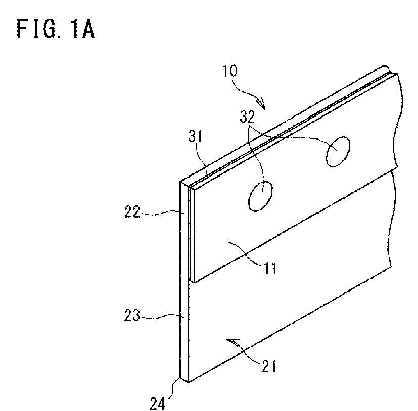
- FIGS. 1A and 1B are views illustrating a sealing member for machine tools according to a first embodiment.
- FIG. 1A is a perspective view and FIG. 1B is a side view.
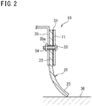
- FIG. 2 is a cross-sectional view illustrating a state in which the sealing member for machine tools according to the first embodiment is mounted to a machine tool.
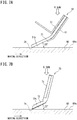
- FIG. 3 is a cross-sectional view schematically illustrating a using state of the sealing member for machine tools according to the first embodiment.
- a sealing member for machine tools 10 includes a support member 11 formed in a flat plate shape, and an elastic member 21 formed in a flat plate shape.
- the support member 11 has a support surface 11a facing a part of a front surface 21a of the elastic member 21.
- the support surface 11a is joined to the front surface 21a of the elastic member 21 via an adhesive layer 31.
- the sealing member for machine tools 10 is mounted to a mount portion 35 of a machine tool.
- the elastic member 21 is a flat plate member in a natural state before the sealing member for machine tools 10 is mounted to the machine tool.
- the elastic member 21 is formed by a fixed portion 22 sandwiched between the mount portion 35 and the support surface 11a of the support member 11 and a lip portion 23 not sandwiched between the mount portion 35 and the support surface 11a when the sealing member for machine tools 10 is mounted to the machine tool.
- the lip portion 23 includes an edge portion 24. The lip portion 23 can be curved.
- a distance L2 between a side surface 21c at a side of the edge portion 24 and a side surface 21d that faces the side surface 21c at an opposite side is longer than a distance L1 of the support surface 11a in the same direction.
- the sealing member for machine tools 10 includes a plurality of bolt holes 32 for mounting the sealing member for machine tools 10 to the machine tools.
- Each of the bolt holes 32 is formed to penetrate the support member 11 and the elastic member 21.
- the sealing member for machine tools 10 is mounted to the mount portion 35 of the machine tool by using a bolt 33 and a nut 34 such that the elastic member 21 is sandwiched between the mount portion 35 of the machine tool and the support member 11.
- the sealing member for machine tools 10 is mounted to the machine tool such that the lip portion 23 of the elastic member 21 is curved to a side opposite to the mount portion 35 of the machine tool, and the edge portion 24 of the elastic member 21 is contacted with a sliding surface 36 of the machine tool.
- the edge portion 24 of the elastic member 21 is slid on the sliding surface 36 of the machine tool so that coolant or a chip are prevented from entering into a driving mechanism or the like of the machine tool.
- the sealing member for machine tools 10 Since the sealing member for machine tools 10 has the configuration described above, contact pressure between the edge portion 24 and the sliding surface 36 is hardly changed when in use (when the sealing member for machine tools 10 is slid on the sliding surface 36 of the machine tool). Thus, the edge portion 24 is hardly worn. Accordingly, in the sealing member for machine tools 10, a time period that can keep the sealing performance becomes remarkably long compared to a conventional sealing member for machine tools.
- the contact pressure of the edge portion 24 becomes large.
- the unevenness of the sliding surface 36 is absorbed by the properties of the elastic member or by forming the groove in a part of the elastic member so that an increase of the contact pressure is avoided.
- the sealing member for machine tools 10 when the sealing member for machine tools 10 is slid on the projection part of the sliding surface (for example the part 36a), a whole of the lip portion 23 of the elastic member 21 can be deformed little by little.
- the sealing member for machine tools 10 not a specific part of the lip portion 23 but a whole of the lip portion 23 is deformed little by little (a curve state of a whole of the lip portion is changed), and thereby the unevenness of the sliding surface 36 can be absorbed and the increase of the contact pressure of the edge portion 24 can be avoided.
- the sealing member for machine tools 10 has excellent wear resistance because the change of the contact pressure when in use is made small.
- the sealing member for machine tools 10 even if the edge portion 24 of the sealing member for machine tools 10 is worn when in use, a whole of the lip portion 23 is deformed little by little. Also in this case, the change of the contact pressure of the edge portion 24 can be made small.
- Such an effect becomes more remarkable as a setting value of a distal end pressing amount (a pressing amount of the edge portion) when mounting the sealing member for machine tools to the machine tool becomes large. This is because the edge portion of the sealing member for machine tools is worn more easily as an initial distal end pressing amount becomes large.
- the edge portion 24 is formed by a side sandwiched between the rear surface 21b and the side surface 21c of the elastic member 21.
- a portion adjacent to the edge portion 24 of the rear surface 21b of the elastic member 21 is also contacted with the sliding surface 36. That is, in the sealing member for machine tools 10, the elastic member 21 (the lip portion) and the sliding surface 36 of the machine tool are in surface contact with each other.
- the sealing member for machine tools 10 has excellent sealing performance compared to a case in which the elastic member 21 and the sliding surface 36 are in linear contact with each other.
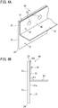
- FIGS. 4A and 4B are views illustrating a sealing member for machine tools according to a second embodiment.
- FIG. 4A is a perspective view
- FIG. 4B is a side view.
- the same reference sign is assigned to a component in FIGS. 4A and 4B which is the same as that in the sealing member for machine tools according to the first embodiment.
- a shape of a support member 41 is different from that in the first embodiment, and other configuration is similar to that of the sealing member for machine tools according to the first embodiment.
- the support member 41 of the sealing member for machine tools 40 includes a support portion 42 formed in a flat plate shape having a support surface 41a facing a front surface 21a of an elastic member 21, and a protection portion 43 formed in a flat plate shape vertically arranged at a side opposite to the support surface 41a of the support portion 42.
- the sealing member for machine tools 40 can protect the front surface 21a of the elastic member 21 from a chip when in use. Thus, it can be suppressed that the elastic member 21 is damaged due to collision of the chip when in use.
- a metal plate subjected to a bending process can be used as the support member 41 including the support portion 42 and the protection portion 43 .
- a bending angle ⁇ 1 of the protection portion 43 against the support portion 42 is not especially limited, however the bending angle ⁇ 1 is normally set in a range between 80° and 150°.
- the sealing member for machine tools 40 is used after mounted to the machine tool by a method as same as that of the sealing member for machine tools 10 according to the first embodiment.
- FIG. 5 is a cross-sectional view of a sealing member for machine tools according to a third embodiment.
- the same reference sign is assigned to a component in FIG. 5 which is the same as that in the sealing member for machine tools according to the first and second embodiments.
- a sealing member for machine tools 50 according to the third embodiment further includes a curve auxiliary member 51 at a side of a rear surface 21b of an elastic member 21 in addition to the configuration of the sealing member for machine tools 40 according to the second embodiment.
- the curve auxiliary member 51 includes a body portion 52 formed in a flat plate shape and an auxiliary portion 53 formed in a flat plate shape.
- the auxiliary portion 53 is obliquely extended from a lower end potion of the body portion 52 to a curve side (a side of a support member 41) of the elastic member 21 (the lip portion 23). Further, the auxiliary portion may be curved.
- the body portion 52 of the curve auxiliary member 51 is joined to a part of a rear surface 21b of the elastic member 21 via an adhesive layer 38.
- auxiliary member 51 including the body portion 52 and the auxiliary portion 53
- a metal plate subjected to a bending process can be used.
- a bending angle ⁇ 2 of the auxiliary portion 53 against the body portion 52 is not especially limited, however the bending angle ⁇ 2 is normally set in a range between 15° and 60°.
- the sealing member for machine tools 50 is used after mounted such that the curve auxiliary member 51, the elastic member 21, and the support member 41 are arranged in this order from a side of a mount portion (not shown) of the machine tool.
- the sealing member for machine tools 50 includes the curve auxiliary member 51, the sealing member for machine tools 50 is suitable for mounting the sealing member for machine tools 50 to the machine tool without making a mistake with respect to a mount direction of the sealing member for machine tools 50.
- the sealing member for machine tools 50 a curve of the lip portion 23 of the elastic member 21 is supported by the curve auxiliary member 51.
- turn-up (reverse of the lip portion 23 of the elastic member 21) of the sealing member for machine tools is hardly generated when in use.
- the front surface 53a of the auxiliary portion 53 and the rear surface 21b of the elastic member 21 may not be necessarily contacted when in use.
- the elastic member 21 and the curve auxiliary member 51 are joined to each other via the adhesive layer 38, and thereby it is further suitable for preventing the coolant from entering through between the elastic member 21 and the curve auxiliary member 51.
- each of the sealing members for machine tools the support member and the elastic member, and the elastic member and the curve auxiliary member are joined via the adhesive layers.
- the support member and the elastic member, and the elastic member and the curve auxiliary member are not necessarily joined via the adhesive layers, and therefore they may merely physically adhere to each other.
- each of the support member, the elastic member and the curve auxiliary member can be replaced independently.
- the sealing member for machine tools according to the third embodiment may include a support member formed in a flat plate shape similar to the support member of the sealing member for machine tools according to the first embodiment.
- the elastic member formed in a flat plate shape is not limited to a perfect rectangular parallelepiped, and for example, a C-chamfered shape or an R-chambered shape subjected to the edge portion described above may be adopted. Further, the elastic member described above may be formed in a shape tapered (a thickness is reduced) continuously or intermittently toward the edge portion in a cross-sectional shape (a shape in a plane orthogonal to the longitudinal direction).
- the support member is formed to firmly fix the elastic member to the machine tool.
- a metal material such as steel and aluminum is generally preferable from a viewpoint of durability and strength.
- the material of the support member may be ceramic, rigid plastic, or the like.
- a steel plate with an untreated surface a steel plate subjected to surface treatment such as zinc phosphate treatment, chromate treatment, and anti-rust resin treatment, an elastic metal plate such as phosphor copper and spring steel, and the like may be adopted.
- surface treatment by using primer may be applied to the support member.
- surface roughening treatment may be applied to the surface of the support member (in particular, a region to be contacted with the elastic member via the adhesive layer) in order to improve adhesiveness by using an anchor effect.
- the elastic member is formed to slide on the sliding surface of the machine tool.
- the edge portion is contacted with the sliding surface of the machine tool.
- the sealing member for machine tools, and therefore examples of the material of the elastic member include NBR (nitrile butadiene rubber), urethane elastomer, fluororubber, silicon rubber, and EPDM (ethylene-propylene-diene rubber).
- NBR nonrile butadiene rubber
- urethane elastomer urethane elastomer
- fluororubber fluororubber
- silicon rubber silicon rubber
- EPDM ethylene-propylene-diene rubber
- the urethane elastomer is preferable because durability (wear resistance) is superior for keeping desirable properties for a long period of time.
- urethane elastomer examples include a product obtained by reaction with a polyol and a polyisocyanate, and a crosslinker as necessary.
- the polyol is not especially limited.
- Examples of the polyol include polyester polyol, polyether polyol, and polycaprolactone polyol.
- the number average molecular weight of the polyol is in a range between 1000 and 3000.
- the number average molecular weight is a measurement value in terms of polystyrene measured by the GPC (Gel Permeation Chromatography) measurement.
- Example of the polyester polyol includes polyester polyol obtained by reacting dicarboxylic acid and glycol in accordance with a routine procedure.
- dicarboxylic acid examples include aromatic dicarboxylic acid such as terephthalic acid, isophthalic acid, and 2,6-naphthalene dicarboxylic acid; aliphatic dicarboxylic acid such as adipic acid, azelaic acid, and sebacic acid; oxycarbonic acid such as oxybenzoic acid; and its ester-forming derivative.
- aromatic dicarboxylic acid such as terephthalic acid, isophthalic acid, and 2,6-naphthalene dicarboxylic acid
- aliphatic dicarboxylic acid such as adipic acid, azelaic acid, and sebacic acid
- oxycarbonic acid such as oxybenzoic acid
- ester-forming derivative examples of the dicarboxylic acids, the adipic acid is preferable because of its excellent wear resistance.
- glycol examples include aliphatic glycol such as ethylene glycol, 1,4-butanediol, diethylene glycol, neopentyl glycol, 3-methyl-1,5-pentanediol, 1,9-nonanediol, triethylene glycol; alicyclic glycol such as 1,4-cyclohexane dimethanol; aromatic diol such as p-xylene diol; and polyoxyalkylene glycol such as polyethylene glycol, polypropylene glycol, and polytetramethylene glycol.
- the aliphatic glycol is preferable, and the ethylene glycol and the 1,4-butanediol are more preferable.
- the polyester polyol which is a reactant of dicarboxylic acid and glycol, has a linear structure, however branched polyester using a trivalent or more ester forming component may be adopted.
- polyether polyol examples include polyalkylene glycols such as polyethylene glycol, polypropylene glycol, polytetramethylene glycol, and copolymers thereof. Of these polyester polyols, the polytetramethylene glycol is preferable because of its excellent wear resistance.
- Example of the polycaprolactone polyol includes polycaprolactone polyol obtained by the ring opening addition of ⁇ -caprolactone using low molecular weight glycol as an initiator in the presence of a catalyst.
- dihydric alcohol such as ethylene glycol, propylene glycol, 1,3-butylene glycol, and neopentyl glycol
- trihydric alcohol such as trimethylene glycol, and glycerin is preferably used.
- the catalyst examples include an organotitanium-based compound such as tetrabutyl titanate, tetrapropyl titanate, and tetraethyl titanate; and a tin-based compound such as tin octylate, dibutyl tin oxide, dibutyl tin laurate, stannous chloride, and stannous bromide.
- organotitanium-based compound such as tetrabutyl titanate, tetrapropyl titanate, and tetraethyl titanate
- a tin-based compound such as tin octylate, dibutyl tin oxide, dibutyl tin laurate, stannous chloride, and stannous bromide.
- ring lactone such as trimethyl caprolactone and valerolactone may be mixed in part in addition to the ⁇ -caprolactone.
- the polyol may be used independently or two or more kinds of the polyols may be used together.
- the polyisocyanate is not especially limited, and therefore conventional known polyisocyanate may be used.
- Examples of the polyisocyanate include aliphatic isocyanate, alicyclic isocyanate, and aromatic isocyanate. Of these polyisocyanates, the aromatic isocyanate is preferable because of its excellent wear resistance.
- aliphatic isocyanate examples include 1,6-hexamethylene diisocyanate (HDI), 2,2,4-trimethylhexamethylene diisocyanate, and lysine diisocyanate. Further, examples of the aliphatic isocyanate also include modified products such as isocyanurate, biuret and adduct of hexamethylene diisocyanate or isophorone diisocyanate.
- HDI 1,6-hexamethylene diisocyanate
- 2,2,4-trimethylhexamethylene diisocyanate examples of the aliphatic isocyanate
- modified products such as isocyanurate, biuret and adduct of hexamethylene diisocyanate or isophorone diisocyanate.
- alicyclic isocyanate examples include isophorone diisocyanate (IPDI), 4,4'-dicyclohexylmethane diisocyanate, 1,4-cyclohexane diisocyanate, and norbornane diisocyanate (NBDI).
- IPDI isophorone diisocyanate
- NBDI norbornane diisocyanate
- aromatic isocyanate examples include 4,4'-diphenylmethane diisocyanate, polymethylene polyphenylene polyisocyanate, a compound of diphenylmethane diisocyanate and polymethylene polyphenylene polyisocyanate (hereinafter, these are also collectively referred to as MDI); tolylene diisocyanate (TDI), phenylene diisocyanate, 1,5-naphthalene diisocyanate, xylylene diisocyanate (XDI), carbodiimide-modified MDI, and urethane-modified MDI.
- MDI 4,4'-diphenylmethane diisocyanate
- polymethylene polyphenylene polyisocyanate a compound of diphenylmethane diisocyanate and polymethylene polyphenylene polyisocyanate
- MDI tolylene diisocyanate
- TDI tolylene diisocyanate
- XDI phenylene di
- the polyisocyanate is used independently or two or more kinds of the polyisocyanates may be used together.
- crosslinking agent examples include ethylene glycol, propylene glycol, butanediol, hexanediol, diethylene glycol, trimethylolpropane, glycerin, hydrazine, ethylenediamine, diethylenetriamine, 4,4'-diaminodiphenyl methane, 4,4'-diaminodicyclohexyl methane, N,N-bis (2-hydroxypropyl) aniline, and water.
- the butanediol and the trimethylolpropane are preferable because of their excellent oil resistance.
- the crosslinking agent may be used independently or two or more kinds of the crosslinking agents may be used together.
- the polyurethane elastomer can be produced by a known method using the materials described above. Specifically, for example, the polyurethane elastomer can be produced by adjusting an equivalent ratio of NCO/OH of each material is set to 0.9 to 1.1 and by reacting the materials in an appropriate organic solvent using a catalyst as needed, or by subjecting the materials to melting reaction without using a solvent.
- the polyurethane elastomer can be produced by a one shot method, a prepolymer method, or the like.
- a molding method of the elastic member is not especially limited. Examples of the molding method include atmospheric pressure cast molding, reduced pressure cast molding, centrifugal casting, continuous rotation molding, extrusion molding, injection molding, reactive injection molding (RIM), and spin coating.
- the molding method include atmospheric pressure cast molding, reduced pressure cast molding, centrifugal casting, continuous rotation molding, extrusion molding, injection molding, reactive injection molding (RIM), and spin coating.
- the centrifugal casting and the continuous rotation molding are preferable.
- a hardness of the elastic member is preferably set in a range between 55° and 90°.
- the hardness of the elastic member is less than 55°, the elastic member is deformed largely when sliding on the sliding surface of the machine tool, and therefore a chip or the like might not be prevented from entering firmly.
- the hardness of the elastic member is more than 90°, the elastic member is too hard and therefore the elastic member might be damaged when sliding.
- the hardness of the elastic member is more preferably set in a range between 60° and 75°.
- the JIS A hardness is a value measured by a spring type A hardness testing machine in accordance with JIS K 7312.
- An impact resilience of the elastic member is preferably set in a range between 10% and 50%.
- the impact resilience of the elastic member is more preferably set in a range between 20% and 40%.
- the impact resilience is a value measured in accordance with JIS K 7312.
- the elastic member may contain various additives. By adding the additive into the elastic member, for example, the hardness, a friction coefficient, or the like of the elastic member can be adjusted.
- the additive examples include powder formed of metal such as metal oxide such as cerium oxide, zinc oxide, iron oxide and silica, metal such as copper, nickel, iron and aluminum; short fiber formed of metal such as aluminum, stainless steel and iron, or short fiber formed of resin such as polyamide; and hollow particles such as glass balloon and fly ash balloon.
- metal oxide such as cerium oxide, zinc oxide, iron oxide and silica
- metal such as copper, nickel, iron and aluminum
- short fiber formed of metal such as aluminum, stainless steel and iron, or short fiber formed of resin such as polyamide
- hollow particles such as glass balloon and fly ash balloon.
- a content of the additive is preferably set in a range between 1 and 100 parts by weight against 100 parts by weight of the rubber component (elastomer component).
- the powder of metal oxide is preferable because the metal oxide easily conforms to the rubber component (elastomer component) and the metal oxide is chemically stable, and the powder of cerium oxide is more preferable.
- the elastic member may contain, for example, a chain extender compounded in raw material, a reaction assistant such as a crosslinking promoter and a crosslinking retarder, a hydrolysis inhibitor, a colorant, a light stabilizer, a heat stabilizer, an antioxidant, a mildew proofing agent, a flame retardant, an extender, in addition to the additive described above.
- a reaction assistant such as a crosslinking promoter and a crosslinking retarder
- a hydrolysis inhibitor such as a crosslinking promoter and a crosslinking retarder
- a colorant such as a light stabilizer, a heat stabilizer, an antioxidant, a mildew proofing agent, a flame retardant, an extender, in addition to the additive described above.
- the adhesive layer that fixes the elastic member and the support member, and the adhesive layer that fixes the elastic member and the curve auxiliary member are not especially limited.
- the adhesive layer may be appropriately determined in consideration of materials of each member.
- the adhesive layer examples include EVA-based, polyamide-based, or polyurethane-based hot melt adhesive, and a curing type adhesive. Further, for example, a double-sided adhesive tape is also included in the adhesive layer.
- the adhesive layer that joins the elastic member and the support member and the adhesive layer that joins the elastic member and the curve auxiliary member may be formed of the same material or different materials.
- a thickness of the adhesive layer is not especially limited, however the thickness is preferably set in a range between 50 ⁇ m and 500 ⁇ m.
- the sealing member for machine tools can be used as a seal member for protecting a working portion, a driving mechanism or the like in various machine tools such as a lathe and a machining center, from a chip, coolant or the like.
- the sealing member for machine tools can be used as a lip seal, a slide seal, a telescopic seal, a cover seal, or the like.
- the sealing member for machine tools according to each embodiment of the present invention is especially suitable to a lip seal.
- Prepolymer was obtained by adding 39.5 parts by weight of pure MDI (Millionate MT produced by Tosoh Corporation) into 100 parts by weight of polyethylene adipate ester diol (SANESTER 2620 having a hydroxy value of 56.1 mgKOH/g produced by Sanyo Chemical Industries, Ltd.) and by defoaming them under reduced pressure at an atmosphere of 75°C and then by reacting them for 8 hours while agitating them at the same temperature atmosphere. A NCO concentration of the prepolymer was 6.5%.
- an urethane composition was prepared by adding 4.0 parts by weight of powder of cerium oxide (Seriko CH-BS302 produced by TAIYO KOKO CO., LTD.), 6.14 parts by weight of 1,4-butanediol (produced by Mitsui Chemicals, Inc.) and 0.683 parts by weight of trimethylolpropane (produced by MITSUBISHI GAS CHEMICAL COMPANY, INC.) into the obtained prepolymer and then by agitating and mixing them.
- cerium oxide Seiko CH-BS302 produced by TAIYO KOKO CO., LTD.
- 1,4-butanediol produced by Mitsui Chemicals, Inc.
- trimethylolpropane produced by MITSUBISHI GAS CHEMICAL COMPANY, INC.
- the obtained urethane composition was entered into a centrifugal molding machine and the urethane composition was crosslinked in a condition of a molding die temperature of 150 °C and a crosslinking time of 60 minutes, and then a cylindrical cured product having a thickness of 1.6 mm was molded and released from the molding die. After that, one part of the cured product was cut to be developed into a plate shape, and then post-crosslinking was performed in a condition of 120 °C in a blower oven for 12 hours, so that a polyurethane raw sheet was obtained.
- the raw sheet was cut into a sheet of a width 36 mm and a length of 600 mm so that the elastic member formed of the urethane sheet was obtained.
- the JIS A hardness of the urethane sheet was 78°.
- the JIS A hardness of the urethane sheet was measured in accordance with JIS K 7312.
- the JIS A hardness was measured by laminating ten sheets of the urethane sheet having a thickness of 1.6 mm.
- the curve auxiliary member 51 a portion of 20 mm from the one long side is the main portion 52, and the remaining portion is the auxiliary portion 53.
- the support member was fixed at a predetermined position on the front surface of the elastic member by using a double-sided tape having a width of 5 mm (No. 500 produced by Nitto Denko Corporation).
- the curve auxiliary member was fixed on a predetermined position of the rear surface of the elastic member by using the double-sided tape. After that, a plurality of bolt holes was formed so that the sealing member for machine tools having the shape shown in FIG. 5 was produced.
- a height (H in FIG. 5 ) of the produced sealing member for machine tools is 32 mm.
- a slide seal produced by Nitta Corporation (Nitta slide seal GW-LPV1) is adopted as a sealing member for machine tools according to the present comparative example.
- the sealing members for machine tools produced in the example and the comparative example were mounted to a CNC lathe (NLX3000 produced by DMG MORI CO., LTD.). After that, each of the sealing members for machine tools was used for seven months in the following use condition, and a state of each of the edge portion after use was observed.
- Working time 7.5 hours/day.
- Working rate approximately 50%.
- Cut material iron or aluminum (each of which includes casting).
- Coolant synthetic type coolant (Moresco Bio60E produced by MORESCO Corporation). Here, the coolant was used by diluting a raw liquid to 20 times (volume base) with tap water.
- FIG. 6 is a schematic view for describing the mount portion of the sealing member for machine tools.
- a lathe 100 used in the present evaluation include a main spindle 101 supported in a rotatable manner by a headstock (not shown), and a tool rest 102 mounted on a guide rail (not shown) in a movable manner along an axial direction of the main spindle 101.
- Fixed covers 103, 104 that protect the headstock, and a moving cover 105 that moves together with the tool rest 102 are arranged in the lathe 100.
- the lathe 100 prevents a chip or coolant from being scattered to the outside of a cutting space and from adhering to the headstock or the guide rail, by these covers 103, 104, 105.
- the present evaluation was performed by mounting a sealing member for machine tools 110, which seals a gap between the fixed cover 103 and the moving cover 105 and prevents a chip or coolant from entering into the gap, to a side end surface of the fixed cover 103 facing the moving cover 105.
- the dynamic friction coefficient of the edge portion of each of the sealing members for machine tools according to the example and the comparative example before and after the sealing member for machine tools 110 is mounted to the CNC lathe (before and after the use of the sealing member for machine tools 110) was measured by the following method.
- FIG. 7A is a schematic view illustrating a method of measuring the dynamic friction coefficient of the sealing member for machine tools according to Example 1.
- FIG. 7A is a schematic view illustrating a method of measuring the dynamic friction coefficient of the sealing member for machine tools according to Comparative Example 1.
- the edge portion 24 of the sealing member for machine tools 50 was brought into contact with a PET sheet 60 such that an angle between the rear surface 21b of the elastic member 21 and a surface (mirror surface) 60a of the PET sheet 60 is to be 25°. Further, the edge portion 24 was pressed against the PET film 60 by applying a vertical load of 0.98 N to the sealing member for machine tools 50 downward in the vertical direction from an upper side of the curve auxiliary member 51.
- the reference sign 11 denotes the support member.
- the PET sheet 60 was moved horizontally at a moving speed of 1500 mm/minute (a moving direction is a direction from a left side to a right side of FIG. 7A ).
- a horizontal load F (N) at this time when in the stably sliding excluding an initial peak resistance was detected by a load cell and recorded.
- a record chart was processed in calculation averaging processing by using an analyzer so that the dynamic friction coefficient was calculated.
- An edge portion 74 of a sealing member for machine tools 70 was brought into contact with the PET sheet 60 such that an angle between a rear surface 72b of a lip portion 72 and the surface (mirror surface) 60a of the PET sheet 60 is to be 25°. Further, the edge portion 74 was pressed against the PET film 60 by applying a vertical load of 0.98 N to the sealing member for machine tools 70 downward in the vertical direction from an upper side of a reinforcing plate 71.
- the PET sheet 60 was moved horizontally at a moving speed of 1500 mm/minute (a moving direction is a direction from a left side to a right side of FIG. 7B ).
- a horizontal load F (N) at this time when in the stably sliding excluding an initial peak resistance was detected by a load cell and recorded.
- a record chart was processed in calculation averaging processing by using the analyzer so that the dynamic friction coefficient was calculated.
- the measurement of the dynamic friction coefficient of the sealing member for machine tools before the use was performed in a dry condition in a state in which the surface 60a of the PET sheet 60 is clean
- the measurement of the dynamic friction of the sealing member for machine tools after the use was performed in a wet condition in which the surface 60a of the PET sheet 60 is wet with the coolant.
- the wet condition was set to a state in which approximately 5 ml of 20 times diluted aqueous solution of Moresco Bio60E was dropped on the contact portion of the PET sheet with the edge portion of the sealing member for machine tools.
- Example 1 entering of chips into the gap between the fixed cover 103 and the moving cover 105 was observed, however the number of the chips is merely several number. On the other hand, in Comparative Example 1, entering of a large number of the chips into the gap between fixed cover 103 and the moving cover 105 was observed.
Landscapes
- Engineering & Computer Science (AREA)
- Mechanical Engineering (AREA)
- Sealing Devices (AREA)
- Sealing With Elastic Sealing Lips (AREA)
- Sealing Material Composition (AREA)
Abstract
Description
- The present invention relates to a sealing member for machine tools.
- Machine tools such as a lathe and a machining center is the most basic machine device generally used in manufacturing industries. In these machine tools, in order to protect a driving mechanism or the like from a chip, coolant (cutting oil) or the like, or in order to remove the chip or the coolant, a sealing member for machine tools (also referred to as a wiper for machine tools) such as a lip seal, a slide seal, a telescopic seal, and a cover seal is used.
- For example, a sealing member for machine tools (a wiper for machine tools) disclosed in Patent Literature 1 is known.
- Patent Literature 1 discloses a sealing member for machine tools (a wiper for machine tools) 130 shown in
FIG. 10. FIG. 10 is a cross-sectional view illustrating one example of a conventional sealing member for machine tools. - As shown in
FIG. 10 , the wiper for machine tools (hereinafter, also referred to as merely a wiper) 130 is formed in a plate shape. The wiper formachine tools 130 includes amount portion 131 for mounting thewiper 130 to a machine tool, and alip portion 132 formed in a plate shape and bent from themount portion 131. - In the
wiper 130, themount portion 131 is formed of a rubber body with ametal reinforcing plate 134 arranged on a front surface thereof. The rubber body is vulcanized and bonded to the reinforcingplate 134. Thelip portion 132 is formed of rubber integrally with the rubber body of themount portion 131. Agroove 135 extended in a longitudinal direction (a penetration direction of a paper) and formed in an arc shape in cross section is formed at a side of the front surface of a connection portion between themount portion 131 and thelip portion 132. Further, a plurality of screw holes 133 is formed on themount portion 131. - A
metal plate 136 is arranged at a side of arear surface 132A of thelip portion 132. A front surface of themetal plate 136 is stuck to therear surface 132A of thelip portion 132 so as to be completely covered by thelip portion 132. - The
wiper 130 is mounted to afixed cover 128 of the machine tool by inserting ascrew 141 into the screw hole 133 of themount portion 131. At this time, themount portion 131 is mounted such that avertical surface 131A is arranged along thefixed cover 128 so that thevertical surfaces 131A, 131C of themount portion 131 are arranged orthogonal to a slidingsurface 124 of the machine tool. - Further, the
lip portion 132 is inclined against thesliding surface 124, and thereby therear surface 132A of thelip portion 132 is arranged to face thesliding surface 124, and themetal plate 136 stuck to therear surface 132A is arranged at a lower side of thelip portion 132. - Patent Literature 1 makes the following assertion relating to the
wiper 130. - Since the
groove 135 is formed in the connection portion between themount portion 131 and thelip portion 132, thewiper 130 can swing in a vertical direction by relatively small force around the connection portion between thelip portion 132 and themount portion 131 as a fulcrum. Accordingly, even in a case in which thesliding surface 124 is uneven in the vertical direction, thelip portion 132 is adapted to thesliding surface 124 with a good responsiveness, and therefore thelip portion 132 is not separated from thesliding surface 124. - Patent Literature 2 proposes a wiper for machine tools having a configuration similar to that of the wiper for machine tools disclosed in Patent Literature 1 except that a canvas or the like is arranged in a lip portion instead of the metal plate.
-
- Patent Literature 1: Japanese Unexamined Patent Publication No.
2007-290070 - Patent Literature 2: Japanese Unexamined Patent Publication No.
2007-83344 - A sealing member for machine tools is used by pressing an end portion of an elastic member (a distal end portion of a lip portion) on a sliding surface of a machine tool with predetermined contact pressure (pressure received by the elastic member from the sliding surface of the machine tool). The predetermined contact pressure described above is normally ensured by setting a distal end pressing amount when mounting the sealing member for machine tools to the machine tool, to a predetermined value.
- On the other hand, the sliding surface of the machine tool is not flat, and generally, the sliding surface of the machine tool has unevenness (recess and projection). Thus, it is difficult that the sealing member for machine tools keeps the predetermined contact pressure when in use due to the unevenness of the sliding surface.
- In order to deal with this problem, in the sealing member for machine tools (the wiper for machine tools) 130 disclosed in Patent Literature 1, the
groove 135 is formed in the connection portion between themount portion 131 and thelip portion 132. In Patent Literature 1, thelip portion 132 can swing in the vertical direction by relatively small force around the connection portion between thelip portion 132 and themount portion 131 as a fulcrum, and therefore even in a case in which the sliding surface is uneven in the vertical direction, thelip portion 132 is adapted to thesliding surface 124 with a good responsiveness. - However, it became obvious from the study of the present inventors that a contact portion of the elastic member with the sliding surface is easily worn in the sealing member for machine tools disclosed in Patent Literature 1. The reason of this is believed that the technique in Patent Literature 1 intends to absorb the unevenness of the sliding surface by the connection portion between the mount portion and the lip portion, and therefore in a case in which the unevenness becomes excessively large, the lip portion cannot be adapted to the sliding surface sufficiently, and as a result, the contact pressure of the elastic member (the lip portion) cannot be kept constant.
- Here, by setting the contact pressure to be low, the wear of the contact portion can be avoided, however sealing performance of the sealing member for machine tools is deteriorated. Thus, when the contact pressure is set to be low, it becomes difficult to achieve the original purpose of the sealing member for machine tools that protects a driving mechanism or the like of the machine tool from a chip, coolant or the like.
- The present inventors conducted a study to solve the problem. As a result, the present inventors newly found a sealing member for machine tools having excellent wear resistance in which a change of contact pressure with a sliding surface is small even if the sliding surface of a machine tool is uneven, and then the present inventors completed the present invention.
- A sealing member for machine tools of the present invention includes a support member, and an elastic member formed in a flat plate shape, the elastic member having an edge portion to be slid on a sliding surface of a machine tool.
- The support member has a support surface facing a part of a front surface of the elastic member.
- The sealing member for machine tools is mounted to the machine tool such that the elastic member is sandwiched between a mount portion of the machine tool and the support surface of the support member.
- The elastic member has a fixed portion sandwiched between the mount portion and the support member and a lip portion not sandwiched between the mount portion and the support member when the sealing member for machine tools is mounted to the machine tool, the lip portion including the edge portion and configured to be curved.
- In the sealing member for machine tools of the present invention, the elastic member, which is a flat plate shape before mounted to the machine tool (before the edge portion of the elastic member is contacted with the sliding surface of the machine tool) is mounted to the machine tool such that the lip portion is curved when the edge portion is pressed against a sliding surface of the machine tool. Further, the sealing member for machine tools is used in a state in which the lip portion is curved.
- Even if the unevenness is formed on the sliding surface of the machine tool, the sealing member for machine tools can absorb the unevenness by a whole of the lip portion of the elastic member. Thus, in the sealing member for machine tools, even if the unevenness is formed on the sliding surface of the machine tool, a change of contact pressure in the edge portion can be made extremely small. Accordingly, in the sealing member for machine tools of the present invention, the edge portion slid on the sliding surface of the machine tool is hardly worn, and therefore sealing performance can be kept for a long period of time.
- Such an effect becomes more remarkable as a distal end pressing amount of the lip portion in mounting the sealing member for machine tools to the machine tool becomes large.
- Further, since the elastic member of the sealing member for machine tools is formed in a flat plate shape, it is not necessary to produce the elastic member by preparing a molding die for each product, contrary to the elastic member (a rubber body formed of a body portion and a lip portion) of the sealing member for machine tools disclosed in each of Patent Literatures 1 and 2. The elastic member formed in a flat plate shape can be produced by producing a sheet like component formed of an elastic material and cutting the obtained sheet like component into a predetermined size. Thus, the sealing member for machine tools has excellent productivity, and the sealing member for machine tools can be adapted to a design change easily.
- In the sealing member for machine tools, it is preferable that the support member has a protection portion arranged at a side opposite to the support surface.
- In this case, the exposed front surface of the elastic member can be protected from a chip when in use of the sealing member for machine tools. Thus, it can be suppressed that the elastic member is damaged due to the collision of the chip when in use.
- In the sealing member for machine tools, it is preferable that the support surface of the support member and the front surface of the elastic member are joined via an adhesive layer.
- In this case, the coolant is hardly entered into a driving mechanism or the like of the machine tool through between the support member and the elastic member. Accordingly, the sealing member for machine tools has further excellent sealing performance.
- It is preferable that the sealing member for machine tools further includes a curve auxiliary member at a side of a rear surface of the elastic member, and
the curve auxiliary member includes a body portion formed in a flat plate shape and an auxiliary portion extended from the body portion toward a side of a curve of the elastic member. - In this case, when the sealing member for machine tools is mounted to the machine tool, the elastic member is easily curved in a predetermined direction, and it can be avoided that a direction to be curved is erroneously set.
- Further, with the curve auxiliary member, reverse of the direction of the elastic member, or turn-up of the sealing member for machine tools (the elastic member) is hardly generated.
- In the sealing member for machine tools, it is preferable that a rear surface of the elastic member and a body portion of the curve auxiliary member are joined via an adhesive layer.
- In this case, the coolant is hardly entered into a driving mechanism or the like of the machine tool through between the elastic member and the curve auxiliary member. Accordingly, the sealing member for machine tools has further excellent sealing performance.
- In the sealing member for machine tools of the present invention, the edge portion to be slid on the sliding surface of the machine tool is hardly worn, and therefore sealing performance can be kept for a long period of time.
-
- [
FIG. 1] FIG. 1A is a perspective view of a part of a sealing member for machine tools according to a first embodiment, andFIG. 1B is a side view ofFIG. 1A . - [
FIG. 2] FIG. 2 is a cross-sectional view illustrating a state in which the sealing member for machine tools according to the first embodiment is mounted to a machine tool. - [
FIG. 3] FIG. 3 is a cross-sectional view schematically illustrating a using state of the sealing member for machine tools according to the first embodiment. - [
FIG. 4] FIG. 4A is a perspective view of a part of a sealing member for machine tools according to a second embodiment, andFIG. 4B is a side view ofFIG. 4A . - [
FIG. 5] FIG. 5 is a side view of a sealing member for machine tools according to a third embodiment. - [
FIG. 6] FIG. 6 is a schematic view for describing a mount portion of a sealing member for machine tools in evaluation of an example and a comparative example. - [
FIG. 7] FIG. 7A is a schematic view illustrating a method of measuring a dynamic friction coefficient of a sealing member for machine tools according to Example 1, andFIG. 7B is a schematic view illustrating a method of measuring a dynamic friction coefficient of a sealing member for machine tools according to Comparative Example 1. - [
FIG. 8] FIG. 8 is a photo showing a state of an edge portion after the evaluation of the sealing member for machine tools according to Example 1. - [
FIG. 9] FIG. 9 is a photo showing a state of an edge portion after the evaluation of the sealing member for machine tools according to Comparative Example 1. - [
FIG. 10] FIG. 10 is a cross-sectional view illustrating one example of a conventional sealing member for machine tools. - Hereinafter, sealing members for machine tools according to embodiments of the present invention are described with reference to drawings.
-
FIGS. 1A and 1B are views illustrating a sealing member for machine tools according to a first embodiment.FIG. 1A is a perspective view andFIG. 1B is a side view.FIG. 2 is a cross-sectional view illustrating a state in which the sealing member for machine tools according to the first embodiment is mounted to a machine tool.FIG. 3 is a cross-sectional view schematically illustrating a using state of the sealing member for machine tools according to the first embodiment. - As shown in
FIGS. 1A and 1B , a sealing member formachine tools 10 according to the first embodiment includes asupport member 11 formed in a flat plate shape, and anelastic member 21 formed in a flat plate shape. Thesupport member 11 has asupport surface 11a facing a part of afront surface 21a of theelastic member 21. Thesupport surface 11a is joined to thefront surface 21a of theelastic member 21 via anadhesive layer 31. As shown inFIG. 2 , the sealing member formachine tools 10 is mounted to amount portion 35 of a machine tool. - The
elastic member 21 is a flat plate member in a natural state before the sealing member formachine tools 10 is mounted to the machine tool. Theelastic member 21 is formed by a fixedportion 22 sandwiched between themount portion 35 and thesupport surface 11a of thesupport member 11 and alip portion 23 not sandwiched between themount portion 35 and thesupport surface 11a when the sealing member formachine tools 10 is mounted to the machine tool. Thelip portion 23 includes anedge portion 24. Thelip portion 23 can be curved. - Accordingly, in the
elastic member 21, a distance L2 between aside surface 21c at a side of theedge portion 24 and aside surface 21d that faces theside surface 21c at an opposite side is longer than a distance L1 of thesupport surface 11a in the same direction. - Further, the sealing member for
machine tools 10 includes a plurality of bolt holes 32 for mounting the sealing member formachine tools 10 to the machine tools. Each of the bolt holes 32 is formed to penetrate thesupport member 11 and theelastic member 21. - As shown in
FIG. 2 , the sealing member formachine tools 10 is mounted to themount portion 35 of the machine tool by using abolt 33 and anut 34 such that theelastic member 21 is sandwiched between themount portion 35 of the machine tool and thesupport member 11. - At this time, the sealing member for
machine tools 10 is mounted to the machine tool such that thelip portion 23 of theelastic member 21 is curved to a side opposite to themount portion 35 of the machine tool, and theedge portion 24 of theelastic member 21 is contacted with a slidingsurface 36 of the machine tool. - In the sealing member for
machine tools 10 mounted to the machine tool, theedge portion 24 of theelastic member 21 is slid on the slidingsurface 36 of the machine tool so that coolant or a chip are prevented from entering into a driving mechanism or the like of the machine tool. - Since the sealing member for
machine tools 10 has the configuration described above, contact pressure between theedge portion 24 and the slidingsurface 36 is hardly changed when in use (when the sealing member formachine tools 10 is slid on the slidingsurface 36 of the machine tool). Thus, theedge portion 24 is hardly worn. Accordingly, in the sealing member formachine tools 10, a time period that can keep the sealing performance becomes remarkably long compared to a conventional sealing member for machine tools. - The reason of this is assumed as described below.
- As shown in
FIG. 3 , unevenness (recess and projection) normally exists on the slidingsurface 36 of the machine tool. Thus, a distance (see L3 inFIG. 3 ) between the mount portion 35 (for example, thebolt hole 35a for fixing the sealing member for machine tools 10) and the slidingsurface 36 of the machine tool is not constant. - Thus, when the sealing member for
machine tools 10 is slid on a projection part of the sliding surface 36 (for example, apart 36a inFIG. 3 ), the contact pressure of theedge portion 24 becomes large. In the conventional sealing member for machine tools, the unevenness of the slidingsurface 36 is absorbed by the properties of the elastic member or by forming the groove in a part of the elastic member so that an increase of the contact pressure is avoided. However, as described above, it is difficult to avoid the increase of the contact pressure sufficiently in the conventional technique. - Against this, in the sealing member for
machine tools 10 according to the present embodiment, as shown inFIG. 3 , when the sealing member formachine tools 10 is slid on the projection part of the sliding surface (for example thepart 36a), a whole of thelip portion 23 of theelastic member 21 can be deformed little by little. Thus, in the sealing member formachine tools 10, not a specific part of thelip portion 23 but a whole of thelip portion 23 is deformed little by little (a curve state of a whole of the lip portion is changed), and thereby the unevenness of the slidingsurface 36 can be absorbed and the increase of the contact pressure of theedge portion 24 can be avoided. In this case, the sealing member formachine tools 10 has excellent wear resistance because the change of the contact pressure when in use is made small. - Further, in the sealing member for
machine tools 10, even if theedge portion 24 of the sealing member formachine tools 10 is worn when in use, a whole of thelip portion 23 is deformed little by little. Also in this case, the change of the contact pressure of theedge portion 24 can be made small. - Such an effect becomes more remarkable as a setting value of a distal end pressing amount (a pressing amount of the edge portion) when mounting the sealing member for machine tools to the machine tool becomes large. This is because the edge portion of the sealing member for machine tools is worn more easily as an initial distal end pressing amount becomes large.
- Further, in the sealing member for
machine tools 10 according to the present embodiment, theedge portion 24 is formed by a side sandwiched between therear surface 21b and theside surface 21c of theelastic member 21. In such a sealing member formachine tools 10, when theedge portion 24 is contacted with the slidingsurface 36 of the machine tool in a state in which thelip portion 23 of theelastic member 21 is curved, a portion adjacent to theedge portion 24 of therear surface 21b of theelastic member 21 is also contacted with the slidingsurface 36. That is, in the sealing member formachine tools 10, the elastic member 21 (the lip portion) and the slidingsurface 36 of the machine tool are in surface contact with each other. Thus, the sealing member formachine tools 10 has excellent sealing performance compared to a case in which theelastic member 21 and the slidingsurface 36 are in linear contact with each other. -
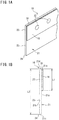
FIGS. 4A and 4B are views illustrating a sealing member for machine tools according to a second embodiment.FIG. 4A is a perspective view, andFIG. 4B is a side view. Here, the same reference sign is assigned to a component inFIGS. 4A and 4B which is the same as that in the sealing member for machine tools according to the first embodiment. - As shown in
FIGS. 4A and 4B , in a sealing member formachine tools 40 according to the second embodiment, a shape of asupport member 41 is different from that in the first embodiment, and other configuration is similar to that of the sealing member for machine tools according to the first embodiment. - The
support member 41 of the sealing member formachine tools 40 includes asupport portion 42 formed in a flat plate shape having asupport surface 41a facing afront surface 21a of anelastic member 21, and aprotection portion 43 formed in a flat plate shape vertically arranged at a side opposite to thesupport surface 41a of thesupport portion 42. - Since the
support member 41 includes theprotection portion 43, the sealing member formachine tools 40 can protect thefront surface 21a of theelastic member 21 from a chip when in use. Thus, it can be suppressed that theelastic member 21 is damaged due to collision of the chip when in use. - As the
support member 41 including thesupport portion 42 and theprotection portion 43, for example, a metal plate subjected to a bending process can be used. In thesupport member 41, a bending angle θ1 of theprotection portion 43 against thesupport portion 42 is not especially limited, however the bending angle θ1 is normally set in a range between 80° and 150°. - The sealing member for
machine tools 40 is used after mounted to the machine tool by a method as same as that of the sealing member formachine tools 10 according to the first embodiment. -
FIG. 5 is a cross-sectional view of a sealing member for machine tools according to a third embodiment. Here, the same reference sign is assigned to a component inFIG. 5 which is the same as that in the sealing member for machine tools according to the first and second embodiments. - As shown in
FIG. 5 , a sealing member formachine tools 50 according to the third embodiment further includes a curveauxiliary member 51 at a side of arear surface 21b of anelastic member 21 in addition to the configuration of the sealing member formachine tools 40 according to the second embodiment. - The curve
auxiliary member 51 includes abody portion 52 formed in a flat plate shape and anauxiliary portion 53 formed in a flat plate shape. Theauxiliary portion 53 is obliquely extended from a lower end potion of thebody portion 52 to a curve side (a side of a support member 41) of the elastic member 21 (the lip portion 23). Further, the auxiliary portion may be curved. - The
body portion 52 of the curveauxiliary member 51 is joined to a part of arear surface 21b of theelastic member 21 via anadhesive layer 38. - As the curve
auxiliary member 51 including thebody portion 52 and theauxiliary portion 53, for example, a metal plate subjected to a bending process can be used. In theauxiliary member 51, a bending angle θ2 of theauxiliary portion 53 against thebody portion 52 is not especially limited, however the bending angle θ2 is normally set in a range between 15° and 60°. - The sealing member for
machine tools 50 according to the present embodiment is used after mounted such that the curveauxiliary member 51, theelastic member 21, and thesupport member 41 are arranged in this order from a side of a mount portion (not shown) of the machine tool. - Since the sealing member for
machine tools 50 includes the curveauxiliary member 51, the sealing member formachine tools 50 is suitable for mounting the sealing member formachine tools 50 to the machine tool without making a mistake with respect to a mount direction of the sealing member formachine tools 50. - Further, in the sealing member for
machine tools 50, a curve of thelip portion 23 of theelastic member 21 is supported by the curveauxiliary member 51. Thus, turn-up (reverse of thelip portion 23 of the elastic member 21) of the sealing member for machine tools is hardly generated when in use. Here, thefront surface 53a of theauxiliary portion 53 and therear surface 21b of theelastic member 21 may not be necessarily contacted when in use. - Further, in the sealing member for
machine tools 50, theelastic member 21 and the curve auxiliary member 51 (the body portion 52) are joined to each other via theadhesive layer 38, and thereby it is further suitable for preventing the coolant from entering through between theelastic member 21 and the curveauxiliary member 51. - In each of the sealing members for machine tools according to the first to third embodiments, the support member and the elastic member, and the elastic member and the curve auxiliary member are joined via the adhesive layers. However, in each of the sealing members for machine tools according to the embodiments of the present invention, the support member and the elastic member, and the elastic member and the curve auxiliary member are not necessarily joined via the adhesive layers, and therefore they may merely physically adhere to each other. In this case, each of the support member, the elastic member and the curve auxiliary member can be replaced independently.
- In the sealing members for machine tools according to the embodiments of the present invention, the sealing member for machine tools according to the third embodiment may include a support member formed in a flat plate shape similar to the support member of the sealing member for machine tools according to the first embodiment.
- In the sealing members for machine tools according to the embodiments of the present invention, the elastic member formed in a flat plate shape is not limited to a perfect rectangular parallelepiped, and for example, a C-chamfered shape or an R-chambered shape subjected to the edge portion described above may be adopted. Further, the elastic member described above may be formed in a shape tapered (a thickness is reduced) continuously or intermittently toward the edge portion in a cross-sectional shape (a shape in a plane orthogonal to the longitudinal direction).
- Next, each component of the sealing member for machine tools is described.
- The support member is formed to firmly fix the elastic member to the machine tool. As a material of the support member, a metal material such as steel and aluminum is generally preferable from a viewpoint of durability and strength. The material of the support member may be ceramic, rigid plastic, or the like.
- Further, as the material of the support member, a steel plate with an untreated surface, a steel plate subjected to surface treatment such as zinc phosphate treatment, chromate treatment, and anti-rust resin treatment, an elastic metal plate such as phosphor copper and spring steel, and the like may be adopted.
- In order to improve conformability of the support member to the adhesive layer sandwiched between the support member and the front surface of the elastic member, surface treatment by using primer may be applied to the support member.
- Further, surface roughening treatment may be applied to the surface of the support member (in particular, a region to be contacted with the elastic member via the adhesive layer) in order to improve adhesiveness by using an anchor effect.
- The elastic member is formed to slide on the sliding surface of the machine tool. In the elastic member, the edge portion is contacted with the sliding surface of the machine tool.
- Normally, oil resistance is required to the sealing member for machine tools, and therefore examples of the material of the elastic member include NBR (nitrile butadiene rubber), urethane elastomer, fluororubber, silicon rubber, and EPDM (ethylene-propylene-diene rubber).
- Of these materials, the urethane elastomer is preferable because durability (wear resistance) is superior for keeping desirable properties for a long period of time.
- Examples of the urethane elastomer include a product obtained by reaction with a polyol and a polyisocyanate, and a crosslinker as necessary.
- The polyol is not especially limited. Examples of the polyol include polyester polyol, polyether polyol, and polycaprolactone polyol.
- It is preferable that the number average molecular weight of the polyol is in a range between 1000 and 3000. By using the polyol within the range described above, a chip and coolant can be further firmly prevented from entering when in use.
- The number average molecular weight is a measurement value in terms of polystyrene measured by the GPC (Gel Permeation Chromatography) measurement.
- Example of the polyester polyol includes polyester polyol obtained by reacting dicarboxylic acid and glycol in accordance with a routine procedure.
- Examples of the dicarboxylic acid include aromatic dicarboxylic acid such as terephthalic acid, isophthalic acid, and 2,6-naphthalene dicarboxylic acid; aliphatic dicarboxylic acid such as adipic acid, azelaic acid, and sebacic acid; oxycarbonic acid such as oxybenzoic acid; and its ester-forming derivative. Of these dicarboxylic acids, the adipic acid is preferable because of its excellent wear resistance.
- Examples of the glycol include aliphatic glycol such as ethylene glycol, 1,4-butanediol, diethylene glycol, neopentyl glycol, 3-methyl-1,5-pentanediol, 1,9-nonanediol, triethylene glycol; alicyclic glycol such as 1,4-cyclohexane dimethanol; aromatic diol such as p-xylene diol; and polyoxyalkylene glycol such as polyethylene glycol, polypropylene glycol, and polytetramethylene glycol. As the glycol, the aliphatic glycol is preferable, and the ethylene glycol and the 1,4-butanediol are more preferable.
- The polyester polyol, which is a reactant of dicarboxylic acid and glycol, has a linear structure, however branched polyester using a trivalent or more ester forming component may be adopted.
- Examples of the polyether polyol include polyalkylene glycols such as polyethylene glycol, polypropylene glycol, polytetramethylene glycol, and copolymers thereof. Of these polyester polyols, the polytetramethylene glycol is preferable because of its excellent wear resistance.
- Example of the polycaprolactone polyol includes polycaprolactone polyol obtained by the ring opening addition of ε-caprolactone using low molecular weight glycol as an initiator in the presence of a catalyst.
- As the low molecular weight glycol, dihydric alcohol such as ethylene glycol, propylene glycol, 1,3-butylene glycol, and neopentyl glycol; or trihydric alcohol such as trimethylene glycol, and glycerin is preferably used.
- Examples of the catalyst include an organotitanium-based compound such as tetrabutyl titanate, tetrapropyl titanate, and tetraethyl titanate; and a tin-based compound such as tin octylate, dibutyl tin oxide, dibutyl tin laurate, stannous chloride, and stannous bromide.
- Here, when performing the ring opening addition of the ε-caprolactone, other ring lactone such as trimethyl caprolactone and valerolactone may be mixed in part in addition to the ε-caprolactone.
- The polyol may be used independently or two or more kinds of the polyols may be used together.
- The polyisocyanate is not especially limited, and therefore conventional known polyisocyanate may be used. Examples of the polyisocyanate include aliphatic isocyanate, alicyclic isocyanate, and aromatic isocyanate. Of these polyisocyanates, the aromatic isocyanate is preferable because of its excellent wear resistance.
- Examples of the aliphatic isocyanate include 1,6-hexamethylene diisocyanate (HDI), 2,2,4-trimethylhexamethylene diisocyanate, and lysine diisocyanate. Further, examples of the aliphatic isocyanate also include modified products such as isocyanurate, biuret and adduct of hexamethylene diisocyanate or isophorone diisocyanate.
- Examples of the alicyclic isocyanate include isophorone diisocyanate (IPDI), 4,4'-dicyclohexylmethane diisocyanate, 1,4-cyclohexane diisocyanate, and norbornane diisocyanate (NBDI).
- Examples of the aromatic isocyanate include 4,4'-diphenylmethane diisocyanate, polymethylene polyphenylene polyisocyanate, a compound of diphenylmethane diisocyanate and polymethylene polyphenylene polyisocyanate (hereinafter, these are also collectively referred to as MDI); tolylene diisocyanate (TDI), phenylene diisocyanate, 1,5-naphthalene diisocyanate, xylylene diisocyanate (XDI), carbodiimide-modified MDI, and urethane-modified MDI.
- The polyisocyanate is used independently or two or more kinds of the polyisocyanates may be used together.
- Examples of the crosslinking agent include ethylene glycol, propylene glycol, butanediol, hexanediol, diethylene glycol, trimethylolpropane, glycerin, hydrazine, ethylenediamine, diethylenetriamine, 4,4'-diaminodiphenyl methane, 4,4'-diaminodicyclohexyl methane, N,N-bis (2-hydroxypropyl) aniline, and water.
- Of these crosslinking agents, the butanediol and the trimethylolpropane are preferable because of their excellent oil resistance.
- The crosslinking agent may be used independently or two or more kinds of the crosslinking agents may be used together.
- The polyurethane elastomer can be produced by a known method using the materials described above. Specifically, for example, the polyurethane elastomer can be produced by adjusting an equivalent ratio of NCO/OH of each material is set to 0.9 to 1.1 and by reacting the materials in an appropriate organic solvent using a catalyst as needed, or by subjecting the materials to melting reaction without using a solvent.
- The polyurethane elastomer can be produced by a one shot method, a prepolymer method, or the like.
- A molding method of the elastic member is not especially limited. Examples of the molding method include atmospheric pressure cast molding, reduced pressure cast molding, centrifugal casting, continuous rotation molding, extrusion molding, injection molding, reactive injection molding (RIM), and spin coating.
- Of these molding methods, the centrifugal casting and the continuous rotation molding are preferable.
- A hardness of the elastic member (JIS A hardness) is preferably set in a range between 55° and 90°.
- In a case in which the hardness of the elastic member is less than 55°, the elastic member is deformed largely when sliding on the sliding surface of the machine tool, and therefore a chip or the like might not be prevented from entering firmly. On the other hand, in a case in which the hardness of the elastic member is more than 90°, the elastic member is too hard and therefore the elastic member might be damaged when sliding. The hardness of the elastic member is more preferably set in a range between 60° and 75°.
- The JIS A hardness is a value measured by a spring type A hardness testing machine in accordance with JIS K 7312.
- An impact resilience of the elastic member is preferably set in a range between 10% and 50%.
- By setting the impact resilience of the elastic member in the range described above, the elastic member follows the unevenness of the sliding surface further easily and abnormal noise (chattering noise) in sliding is suppressed easily. The impact resilience of the elastic member is more preferably set in a range between 20% and 40%.
- The impact resilience is a value measured in accordance with JIS K 7312.
- The elastic member may contain various additives. By adding the additive into the elastic member, for example, the hardness, a friction coefficient, or the like of the elastic member can be adjusted.
- Examples of the additive include powder formed of metal such as metal oxide such as cerium oxide, zinc oxide, iron oxide and silica, metal such as copper, nickel, iron and aluminum; short fiber formed of metal such as aluminum, stainless steel and iron, or short fiber formed of resin such as polyamide; and hollow particles such as glass balloon and fly ash balloon.
- A content of the additive is preferably set in a range between 1 and 100 parts by weight against 100 parts by weight of the rubber component (elastomer component).
- As the additive, the powder of metal oxide is preferable because the metal oxide easily conforms to the rubber component (elastomer component) and the metal oxide is chemically stable, and the powder of cerium oxide is more preferable.
- The elastic member may contain, for example, a chain extender compounded in raw material, a reaction assistant such as a crosslinking promoter and a crosslinking retarder, a hydrolysis inhibitor, a colorant, a light stabilizer, a heat stabilizer, an antioxidant, a mildew proofing agent, a flame retardant, an extender, in addition to the additive described above.
- The adhesive layer that fixes the elastic member and the support member, and the adhesive layer that fixes the elastic member and the curve auxiliary member are not especially limited. The adhesive layer may be appropriately determined in consideration of materials of each member.
- Examples of the adhesive layer include EVA-based, polyamide-based, or polyurethane-based hot melt adhesive, and a curing type adhesive. Further, for example, a double-sided adhesive tape is also included in the adhesive layer.
- The adhesive layer that joins the elastic member and the support member and the adhesive layer that joins the elastic member and the curve auxiliary member may be formed of the same material or different materials.
- A thickness of the adhesive layer is not especially limited, however the thickness is preferably set in a range between 50 µm and 500 µm.
- The sealing member for machine tools according to each embodiment of the present invention can be used as a seal member for protecting a working portion, a driving mechanism or the like in various machine tools such as a lathe and a machining center, from a chip, coolant or the like. The sealing member for machine tools can be used as a lip seal, a slide seal, a telescopic seal, a cover seal, or the like.
- The sealing member for machine tools according to each embodiment of the present invention is especially suitable to a lip seal.
- Hereinafter, the embodiment of the present invention is more specifically described with reference to examples, however the embodiment of the present invention is not limited to examples described below.
- A steel plate having a thickness of 0.8 mm (Green Coat GX-K2 produced by Kobe Steel, Ltd.) was cut into a size of 34 mm × 600 mm. And then, a part of 18 mm from one long side of the steel plate was bent to be parallel to the long side by 90° so that the
support member 41 having an L-shape shown inFIG. 5 (θ1 = 90°) was formed. In thesupport member 41, a portion of 18 mm from the one long side corresponds to thesupport portion 42, and the remaining portion corresponds to theprotection portion 43. - Prepolymer was obtained by adding 39.5 parts by weight of pure MDI (Millionate MT produced by Tosoh Corporation) into 100 parts by weight of polyethylene adipate ester diol (SANESTER 2620 having a hydroxy value of 56.1 mgKOH/g produced by Sanyo Chemical Industries, Ltd.) and by defoaming them under reduced pressure at an atmosphere of 75°C and then by reacting them for 8 hours while agitating them at the same temperature atmosphere. A NCO concentration of the prepolymer was 6.5%.
- After that, an urethane composition was prepared by adding 4.0 parts by weight of powder of cerium oxide (Seriko CH-BS302 produced by TAIYO KOKO CO., LTD.), 6.14 parts by weight of 1,4-butanediol (produced by Mitsui Chemicals, Inc.) and 0.683 parts by weight of trimethylolpropane (produced by MITSUBISHI GAS CHEMICAL COMPANY, INC.) into the obtained prepolymer and then by agitating and mixing them.
- After that, the obtained urethane composition was entered into a centrifugal molding machine and the urethane composition was crosslinked in a condition of a molding die temperature of 150 °C and a crosslinking time of 60 minutes, and then a cylindrical cured product having a thickness of 1.6 mm was molded and released from the molding die. After that, one part of the cured product was cut to be developed into a plate shape, and then post-crosslinking was performed in a condition of 120 °C in a blower oven for 12 hours, so that a polyurethane raw sheet was obtained.
- Next, the raw sheet was cut into a sheet of a
width 36 mm and a length of 600 mm so that the elastic member formed of the urethane sheet was obtained. The JIS A hardness of the urethane sheet was 78°. - Here, the JIS A hardness of the urethane sheet was measured in accordance with JIS K 7312. The JIS A hardness was measured by laminating ten sheets of the urethane sheet having a thickness of 1.6 mm.
- A steel plate having a thickness of 0.8 mm (Green Coat GX-K2 produced by Kobe Steel, Ltd.) was cut into a size of 24 mm × 600 mm. And then, a part of 20 mm from one long side of the steel plate was bent to be parallel to the long side by 30° so that the curve
auxiliary member 51 shown inFIG. 5 (θ2 = 30°) was formed. In the curveauxiliary member 51, a portion of 20 mm from the one long side is themain portion 52, and the remaining portion is theauxiliary portion 53. - The support member was fixed at a predetermined position on the front surface of the elastic member by using a double-sided tape having a width of 5 mm (No. 500 produced by Nitto Denko Corporation). Next, the curve auxiliary member was fixed on a predetermined position of the rear surface of the elastic member by using the double-sided tape. After that, a plurality of bolt holes was formed so that the sealing member for machine tools having the shape shown in
FIG. 5 was produced. - Here, a height (H in
FIG. 5 ) of the produced sealing member for machine tools is 32 mm. - A slide seal produced by Nitta Corporation (Nitta slide seal GW-LPV1) is adopted as a sealing member for machine tools according to the present comparative example.
- The sealing members for machine tools produced in the example and the comparative example were mounted to a CNC lathe (NLX3000 produced by DMG MORI CO., LTD.). After that, each of the sealing members for machine tools was used for seven months in the following use condition, and a state of each of the edge portion after use was observed.
- Working time: 7.5 hours/day. Working rate: approximately 50%.
- Cut material: iron or aluminum (each of which includes casting).
- Coolant: synthetic type coolant (Moresco Bio60E produced by MORESCO Corporation). Here, the coolant was used by diluting a raw liquid to 20 times (volume base) with tap water.
- Mount portion: see
FIG. 6 . -
FIG. 6 is a schematic view for describing the mount portion of the sealing member for machine tools. - A
lathe 100 used in the present evaluation include amain spindle 101 supported in a rotatable manner by a headstock (not shown), and atool rest 102 mounted on a guide rail (not shown) in a movable manner along an axial direction of themain spindle 101. Fixed covers 103, 104 that protect the headstock, and a movingcover 105 that moves together with thetool rest 102 are arranged in thelathe 100. Thelathe 100 prevents a chip or coolant from being scattered to the outside of a cutting space and from adhering to the headstock or the guide rail, by thesecovers - The present evaluation was performed by mounting a sealing member for
machine tools 110, which seals a gap between thefixed cover 103 and the movingcover 105 and prevents a chip or coolant from entering into the gap, to a side end surface of the fixedcover 103 facing the movingcover 105. - The dynamic friction coefficient of the edge portion of each of the sealing members for machine tools according to the example and the comparative example before and after the sealing member for
machine tools 110 is mounted to the CNC lathe (before and after the use of the sealing member for machine tools 110) was measured by the following method. - The dynamic friction coefficient was measured by using the Heidon type surface property tester (HEIDON-14DR).
FIG. 7A is a schematic view illustrating a method of measuring the dynamic friction coefficient of the sealing member for machine tools according to Example 1.FIG. 7A is a schematic view illustrating a method of measuring the dynamic friction coefficient of the sealing member for machine tools according to Comparative Example 1. - The
edge portion 24 of the sealing member formachine tools 50 was brought into contact with aPET sheet 60 such that an angle between therear surface 21b of theelastic member 21 and a surface (mirror surface) 60a of thePET sheet 60 is to be 25°. Further, theedge portion 24 was pressed against thePET film 60 by applying a vertical load of 0.98 N to the sealing member formachine tools 50 downward in the vertical direction from an upper side of the curveauxiliary member 51. Here, inFIG. 7A , thereference sign 11 denotes the support member. - After that, the
PET sheet 60 was moved horizontally at a moving speed of 1500 mm/minute (a moving direction is a direction from a left side to a right side ofFIG. 7A ). A horizontal load F (N) at this time when in the stably sliding excluding an initial peak resistance was detected by a load cell and recorded. Next, a record chart was processed in calculation averaging processing by using an analyzer so that the dynamic friction coefficient was calculated. - An
edge portion 74 of a sealing member formachine tools 70 was brought into contact with thePET sheet 60 such that an angle between arear surface 72b of alip portion 72 and the surface (mirror surface) 60a of thePET sheet 60 is to be 25°. Further, theedge portion 74 was pressed against thePET film 60 by applying a vertical load of 0.98 N to the sealing member formachine tools 70 downward in the vertical direction from an upper side of a reinforcingplate 71. - After that, the
PET sheet 60 was moved horizontally at a moving speed of 1500 mm/minute (a moving direction is a direction from a left side to a right side ofFIG. 7B ). A horizontal load F (N) at this time when in the stably sliding excluding an initial peak resistance was detected by a load cell and recorded. Next, a record chart was processed in calculation averaging processing by using the analyzer so that the dynamic friction coefficient was calculated. - Each measurement of the dynamic friction coefficient described above was performed in an environment of a temperature of 20 °C to 25 °C and a relative humidity of 40% to 55%.
- Further, in each measurement, the measurement of the dynamic friction coefficient of the sealing member for machine tools before the use was performed in a dry condition in a state in which the
surface 60a of thePET sheet 60 is clean, and the measurement of the dynamic friction of the sealing member for machine tools after the use was performed in a wet condition in which thesurface 60a of thePET sheet 60 is wet with the coolant. The wet condition was set to a state in which approximately 5 ml of 20 times diluted aqueous solution of Moresco Bio60E was dropped on the contact portion of the PET sheet with the edge portion of the sealing member for machine tools. - Dynamic friction coefficient before the use: Example 1 = 0.44, Comparative Example 1 = 0.23.
- Dynamic friction coefficient after the use: Example 1 = 0.49, Comparative Example 1 = 0.81.
- In the sealing member for machine tools according to Example 1, an abrasion mark was observed near the
edge portion 24 in the lip portion of the elastic member after used for seven months, however wear of theedge portion 24 was hardly observed (seeFIG. 8 ). - On the other hand, in the sealing member for machine tools according to Comparative Example 1, wear of the edge portion was observed after used for seven months, and exposure of fiber due to disappearance of the rubber was observed (see
FIG. 9 ). - Further, after the evaluation, the sealing member for machine tools was removed, and a state of the machine tool was observed.
- As a result, in Example 1, entering of chips into the gap between the
fixed cover 103 and the movingcover 105 was observed, however the number of the chips is merely several number. On the other hand, in Comparative Example 1, entering of a large number of the chips into the gap between fixedcover 103 and the movingcover 105 was observed. -
- 10, 40, 50: SEALING MEMBER FOR MACHINE TOOLS
- 11, 41: SUPPORT MEMBER
- 11a, 41a: SUPPORT SURFACE
- 21: ELASTIC MEMBER
- 21a: FRONT SURFACE
- 22: FIXED PORTION
- 23: LIP PORTION
- 24: EDGE PORTION
- 31, 38: ADHESIVE LAYER
- 35: MOUNT PORTION
- 36: SLIDING SURFACE
- 42: SUPPORT PORTION
- 43: PROTECTION PORTION
- 51: CURVE AUXILIARY MEMBER
- 52: BODY PORTION
- 53: AUXILIARY PORTION
- 100: LATHE
Claims (5)
- A sealing member for machine tools comprising:a support member; andan elastic member formed in a flat plate shape, the elastic member comprising an edge portion to be slid on a sliding surface of a machine tool,wherein:the support member comprises a support surface facing a part of a front surface of the elastic member;the sealing member for machine tools is mounted to the machine tool such that the elastic member is sandwiched between a mount portion of the machine tool and the support surface of the support member; andthe elastic member comprises a fixed portion sandwiched between the mount portion and the support member and a lip portion not sandwiched between the mount portion and the support member when the sealing member for machine tools is mounted to the machine tool, the lip portion including the edge portion and configured to be curved.
- The sealing member for machine tools according to claim 1, wherein the support member comprises a protection portion arranged at a side opposite to the support surface.
- The sealing member for machine tools according to claim 1 or 2, wherein the support surface of the support member and the front surface of the elastic member are joined via an adhesive layer.
- The sealing member for machine tools according to any one of claims 1 to 3, further comprising a curve auxiliary member at a side of a rear surface of the elastic member, wherein
the curve auxiliary member includes a body portion formed in a flat plate shape and an auxiliary portion extended from the body portion toward a side of a curve of the elastic member. - The sealing member for machine tools according to any one of claims 1 to 4, wherein a rear surface of the elastic member and a body portion of the curve auxiliary member are joined via an adhesive layer.
Applications Claiming Priority (2)
| Application Number | Priority Date | Filing Date | Title |
|---|---|---|---|
| JP2015251378 | 2015-12-24 | ||
| PCT/JP2016/083090 WO2017110275A1 (en) | 2015-12-24 | 2016-11-08 | Machine-tool seal member |
Publications (3)
| Publication Number | Publication Date |
|---|---|
| EP3395499A1 true EP3395499A1 (en) | 2018-10-31 |
| EP3395499A4 EP3395499A4 (en) | 2019-07-24 |
| EP3395499B1 EP3395499B1 (en) | 2024-07-03 |
Family
ID=59089292
Family Applications (1)
| Application Number | Title | Priority Date | Filing Date |
|---|---|---|---|
| EP16878173.0A Active EP3395499B1 (en) | 2015-12-24 | 2016-11-08 | Seal member with a machine-tool |
Country Status (7)
| Country | Link |
|---|---|
| US (1) | US11260487B2 (en) |
| EP (1) | EP3395499B1 (en) |
| JP (1) | JP6177464B1 (en) |
| KR (1) | KR102156248B1 (en) |
| CN (1) | CN108472781B (en) |
| TW (1) | TWI694890B (en) |
| WO (1) | WO2017110275A1 (en) |
Cited By (1)
| Publication number | Priority date | Publication date | Assignee | Title |
|---|---|---|---|---|
| EP4556684A1 (en) * | 2023-11-15 | 2025-05-21 | RTX Corporation | Slider seal for gas turbine engine |
Families Citing this family (5)
| Publication number | Priority date | Publication date | Assignee | Title |
|---|---|---|---|---|
| JP6535709B2 (en) * | 2017-08-08 | 2019-06-26 | バンドー化学株式会社 | Machine tool seal member |
| KR102746225B1 (en) * | 2019-02-14 | 2024-12-26 | 주식회사 디엔솔루션즈 | Wiper of machine tool |
| JP2022084227A (en) * | 2020-11-26 | 2022-06-07 | バンドー化学株式会社 | Dimension inspection method, scale for dimensional inspection, and method of manufacturing seal member for machine tool |
| CN114042981B (en) * | 2021-12-01 | 2023-03-07 | 南京伟舜机电有限公司 | Precision type workbench for numerically controlled milling machine |
| TWI821078B (en) * | 2022-12-20 | 2023-11-01 | 桓凱股份有限公司 | Automated cutting fluid mixing system |
Family Cites Families (26)
| Publication number | Priority date | Publication date | Assignee | Title |
|---|---|---|---|---|
| US3771799A (en) * | 1971-08-20 | 1973-11-13 | Mather Co | Multi-element fluctuating pressure seal |
| US4522411A (en) * | 1984-10-01 | 1985-06-11 | Chicago Rawhide Mfg. Co. | Fluid seals with self-venting auxiliary lips |
| JPH0248207Y2 (en) * | 1984-11-02 | 1990-12-18 | ||
| JPS62258267A (en) * | 1986-05-02 | 1987-11-10 | Taiho Kogyo Co Ltd | Sealing device |
| JPS6430975A (en) * | 1987-07-24 | 1989-02-01 | Taiho Kogyo Co Ltd | Lip seal device |
| JPH081257B2 (en) * | 1990-08-23 | 1996-01-10 | 株式会社小松製作所 | Oil seal |
| US6182975B1 (en) * | 1993-06-04 | 2001-02-06 | Nok Corporation | Sealing device having an annular space between sealing lips |
| JP3212448B2 (en) * | 1994-06-28 | 2001-09-25 | ニッタ株式会社 | Industrial scraper |
| JP2805134B2 (en) * | 1994-09-12 | 1998-09-30 | オークマ株式会社 | Wiper |
| JP2001310238A (en) * | 2000-04-28 | 2001-11-06 | Nok Corp | Scraper for machine tool |
| JP4648514B2 (en) * | 2000-05-02 | 2011-03-09 | イーグル工業株式会社 | Lip type seal |
| JP2001317635A (en) * | 2000-05-02 | 2001-11-16 | Toyota Industries Corp | Lip type seal |
| CN2448516Y (en) * | 2000-10-26 | 2001-09-19 | 陈佩芳 | Dust cover scraper structure |
| JP4865966B2 (en) * | 2001-08-17 | 2012-02-01 | バンドー化学株式会社 | Wiper components for machine tools |
| JP4102610B2 (en) * | 2002-07-26 | 2008-06-18 | オークマ株式会社 | Wiper and manufacturing method thereof |
| DE10353306A1 (en) * | 2002-11-11 | 2004-05-27 | Kaco Gmbh + Co. Kg | Sealing ring used as a rotary shaft seal, piston sealing ring or rod sealing ring, comprises a fixing part and a sealing part forming an annular washer, which is fixed on a machine part without insertion of a support body |
| JP2005246490A (en) * | 2004-03-01 | 2005-09-15 | Hatakeyama Seisakusho:Kk | Protective cover in movable part of machine tool or the like |
| JP2007083344A (en) | 2005-09-22 | 2007-04-05 | Nitta Ind Corp | Industrial wipers |
| JP3863556B1 (en) | 2006-04-25 | 2006-12-27 | ニッタ株式会社 | Machine tool wiper |
| JP5043481B2 (en) * | 2007-03-15 | 2012-10-10 | オークマ株式会社 | Wiper |
| DE202011110807U1 (en) * | 2011-06-06 | 2016-07-14 | Elringklinger Ag | Radial shaft seal |
| US9016696B2 (en) * | 2011-12-22 | 2015-04-28 | Upsite Technologies, Inc. | Air seal for server rack |
| CN102975079A (en) * | 2012-11-20 | 2013-03-20 | 大连天润新能源科技有限公司 | Scraper-type guide rail protection device |
| CN203611063U (en) * | 2013-09-23 | 2014-05-28 | 上海三一精机有限公司 | Inner protective structure of composite machine tool and machine tool |
| WO2015119030A1 (en) * | 2014-02-06 | 2015-08-13 | バンドー化学株式会社 | Sealing member for machine tools |
| CN104174197B (en) * | 2014-07-19 | 2016-11-23 | 芜湖恒坤汽车部件有限公司 | A kind of chip device for filtering and collecting |
-
2016
- 2016-11-08 CN CN201680075797.9A patent/CN108472781B/en active Active
- 2016-11-08 WO PCT/JP2016/083090 patent/WO2017110275A1/en not_active Ceased
- 2016-11-08 EP EP16878173.0A patent/EP3395499B1/en active Active
- 2016-11-08 KR KR1020187015485A patent/KR102156248B1/en active Active
- 2016-11-08 JP JP2016567942A patent/JP6177464B1/en active Active
- 2016-11-08 US US16/065,574 patent/US11260487B2/en not_active Expired - Fee Related
- 2016-11-17 TW TW105137540A patent/TWI694890B/en active
Cited By (1)
| Publication number | Priority date | Publication date | Assignee | Title |
|---|---|---|---|---|
| EP4556684A1 (en) * | 2023-11-15 | 2025-05-21 | RTX Corporation | Slider seal for gas turbine engine |
Also Published As
| Publication number | Publication date |
|---|---|
| JP6177464B1 (en) | 2017-08-09 |
| KR20180071363A (en) | 2018-06-27 |
| TW201735770A (en) | 2017-10-16 |
| CN108472781A (en) | 2018-08-31 |
| US20200262017A1 (en) | 2020-08-20 |
| CN108472781B (en) | 2021-01-12 |
| US11260487B2 (en) | 2022-03-01 |
| JPWO2017110275A1 (en) | 2017-12-21 |
| EP3395499A4 (en) | 2019-07-24 |
| TWI694890B (en) | 2020-06-01 |
| KR102156248B1 (en) | 2020-09-15 |
| EP3395499B1 (en) | 2024-07-03 |
| WO2017110275A1 (en) | 2017-06-29 |
Similar Documents
| Publication | Publication Date | Title |
|---|---|---|
| EP3395499B1 (en) | Seal member with a machine-tool | |
| US8594553B2 (en) | Cleaning blade for electrophotographic apparatus, and method for producing the same | |
| EP3103584B1 (en) | Sealing member for machine tools | |
| TWI763899B (en) | Sealing parts for machine tools | |
| CN108472782B (en) | Sealing parts for machine tools | |
| JP6948957B2 (en) | Manufacturing method of blades for electrophotographic equipment and blades for electrophotographic equipment | |
| JP6822779B2 (en) | Seal members for machine tools | |
| JP2023013080A (en) | Sealing material for machine tools | |
| CN104704429B (en) | Squeegee for electrophotographic device and manufacturing method thereof | |
| TWI719071B (en) | Sealing member for machine tool |
Legal Events
| Date | Code | Title | Description |
|---|---|---|---|
| STAA | Information on the status of an ep patent application or granted ep patent |
Free format text: STATUS: THE INTERNATIONAL PUBLICATION HAS BEEN MADE |
|
| PUAI | Public reference made under article 153(3) epc to a published international application that has entered the european phase |
Free format text: ORIGINAL CODE: 0009012 |
|
| STAA | Information on the status of an ep patent application or granted ep patent |
Free format text: STATUS: REQUEST FOR EXAMINATION WAS MADE |
|
| 17P | Request for examination filed |
Effective date: 20180711 |
|
| AK | Designated contracting states |
Kind code of ref document: A1 Designated state(s): AL AT BE BG CH CY CZ DE DK EE ES FI FR GB GR HR HU IE IS IT LI LT LU LV MC MK MT NL NO PL PT RO RS SE SI SK SM TR |
|
| AX | Request for extension of the european patent |
Extension state: BA ME |
|
| DAV | Request for validation of the european patent (deleted) | ||
| DAX | Request for extension of the european patent (deleted) | ||
| A4 | Supplementary search report drawn up and despatched |
Effective date: 20190624 |
|
| RIC1 | Information provided on ipc code assigned before grant |
Ipc: B23Q 11/08 20060101AFI20190617BHEP |
|
| STAA | Information on the status of an ep patent application or granted ep patent |
Free format text: STATUS: EXAMINATION IS IN PROGRESS |
|
| 17Q | First examination report despatched |
Effective date: 20201203 |
|
| GRAP | Despatch of communication of intention to grant a patent |
Free format text: ORIGINAL CODE: EPIDOSNIGR1 |
|
| STAA | Information on the status of an ep patent application or granted ep patent |
Free format text: STATUS: GRANT OF PATENT IS INTENDED |
|
| INTG | Intention to grant announced |
Effective date: 20240327 |
|
| RIN1 | Information on inventor provided before grant (corrected) |
Inventor name: KANNAKA, MASATOSHI Inventor name: IWASAKI, NARIAKI Inventor name: ABE, YUKI |
|
| GRAS | Grant fee paid |
Free format text: ORIGINAL CODE: EPIDOSNIGR3 |
|
| GRAA | (expected) grant |
Free format text: ORIGINAL CODE: 0009210 |
|
| STAA | Information on the status of an ep patent application or granted ep patent |
Free format text: STATUS: THE PATENT HAS BEEN GRANTED |
|
| AK | Designated contracting states |
Kind code of ref document: B1 Designated state(s): AL AT BE BG CH CY CZ DE DK EE ES FI FR GB GR HR HU IE IS IT LI LT LU LV MC MK MT NL NO PL PT RO RS SE SI SK SM TR |
|
| REG | Reference to a national code |
Ref country code: CH Ref legal event code: EP |
|
| REG | Reference to a national code |
Ref country code: DE Ref legal event code: R096 Ref document number: 602016088269 Country of ref document: DE |
|
| REG | Reference to a national code |
Ref country code: LT Ref legal event code: MG9D |
|
| REG | Reference to a national code |
Ref country code: NL Ref legal event code: MP Effective date: 20240703 |
|
| PG25 | Lapsed in a contracting state [announced via postgrant information from national office to epo] |
Ref country code: PT Free format text: LAPSE BECAUSE OF FAILURE TO SUBMIT A TRANSLATION OF THE DESCRIPTION OR TO PAY THE FEE WITHIN THE PRESCRIBED TIME-LIMIT Effective date: 20241104 |
|
| REG | Reference to a national code |
Ref country code: AT Ref legal event code: MK05 Ref document number: 1699355 Country of ref document: AT Kind code of ref document: T Effective date: 20240703 |
|
| PG25 | Lapsed in a contracting state [announced via postgrant information from national office to epo] |
Ref country code: NL Free format text: LAPSE BECAUSE OF FAILURE TO SUBMIT A TRANSLATION OF THE DESCRIPTION OR TO PAY THE FEE WITHIN THE PRESCRIBED TIME-LIMIT Effective date: 20240703 |
|
| PG25 | Lapsed in a contracting state [announced via postgrant information from national office to epo] |
Ref country code: PT Free format text: LAPSE BECAUSE OF FAILURE TO SUBMIT A TRANSLATION OF THE DESCRIPTION OR TO PAY THE FEE WITHIN THE PRESCRIBED TIME-LIMIT Effective date: 20241104 Ref country code: NL Free format text: LAPSE BECAUSE OF FAILURE TO SUBMIT A TRANSLATION OF THE DESCRIPTION OR TO PAY THE FEE WITHIN THE PRESCRIBED TIME-LIMIT Effective date: 20240703 |
|
| PG25 | Lapsed in a contracting state [announced via postgrant information from national office to epo] |
Ref country code: NO Free format text: LAPSE BECAUSE OF FAILURE TO SUBMIT A TRANSLATION OF THE DESCRIPTION OR TO PAY THE FEE WITHIN THE PRESCRIBED TIME-LIMIT Effective date: 20241003 |
|
| PG25 | Lapsed in a contracting state [announced via postgrant information from national office to epo] |
Ref country code: GR Free format text: LAPSE BECAUSE OF FAILURE TO SUBMIT A TRANSLATION OF THE DESCRIPTION OR TO PAY THE FEE WITHIN THE PRESCRIBED TIME-LIMIT Effective date: 20241004 Ref country code: FI Free format text: LAPSE BECAUSE OF FAILURE TO SUBMIT A TRANSLATION OF THE DESCRIPTION OR TO PAY THE FEE WITHIN THE PRESCRIBED TIME-LIMIT Effective date: 20240703 Ref country code: PL Free format text: LAPSE BECAUSE OF FAILURE TO SUBMIT A TRANSLATION OF THE DESCRIPTION OR TO PAY THE FEE WITHIN THE PRESCRIBED TIME-LIMIT Effective date: 20240703 |
|
| PG25 | Lapsed in a contracting state [announced via postgrant information from national office to epo] |
Ref country code: BG Free format text: LAPSE BECAUSE OF FAILURE TO SUBMIT A TRANSLATION OF THE DESCRIPTION OR TO PAY THE FEE WITHIN THE PRESCRIBED TIME-LIMIT Effective date: 20240703 |
|
| PG25 | Lapsed in a contracting state [announced via postgrant information from national office to epo] |
Ref country code: LV Free format text: LAPSE BECAUSE OF FAILURE TO SUBMIT A TRANSLATION OF THE DESCRIPTION OR TO PAY THE FEE WITHIN THE PRESCRIBED TIME-LIMIT Effective date: 20240703 |
|
| PG25 | Lapsed in a contracting state [announced via postgrant information from national office to epo] |
Ref country code: IS Free format text: LAPSE BECAUSE OF FAILURE TO SUBMIT A TRANSLATION OF THE DESCRIPTION OR TO PAY THE FEE WITHIN THE PRESCRIBED TIME-LIMIT Effective date: 20241103 Ref country code: AT Free format text: LAPSE BECAUSE OF FAILURE TO SUBMIT A TRANSLATION OF THE DESCRIPTION OR TO PAY THE FEE WITHIN THE PRESCRIBED TIME-LIMIT Effective date: 20240703 |
|
| PG25 | Lapsed in a contracting state [announced via postgrant information from national office to epo] |
Ref country code: CZ Free format text: LAPSE BECAUSE OF FAILURE TO SUBMIT A TRANSLATION OF THE DESCRIPTION OR TO PAY THE FEE WITHIN THE PRESCRIBED TIME-LIMIT Effective date: 20240703 Ref country code: HR Free format text: LAPSE BECAUSE OF FAILURE TO SUBMIT A TRANSLATION OF THE DESCRIPTION OR TO PAY THE FEE WITHIN THE PRESCRIBED TIME-LIMIT Effective date: 20240703 |
|
| PG25 | Lapsed in a contracting state [announced via postgrant information from national office to epo] |
Ref country code: RS Free format text: LAPSE BECAUSE OF FAILURE TO SUBMIT A TRANSLATION OF THE DESCRIPTION OR TO PAY THE FEE WITHIN THE PRESCRIBED TIME-LIMIT Effective date: 20241003 Ref country code: ES Free format text: LAPSE BECAUSE OF FAILURE TO SUBMIT A TRANSLATION OF THE DESCRIPTION OR TO PAY THE FEE WITHIN THE PRESCRIBED TIME-LIMIT Effective date: 20240703 |
|
| PG25 | Lapsed in a contracting state [announced via postgrant information from national office to epo] |
Ref country code: RS Free format text: LAPSE BECAUSE OF FAILURE TO SUBMIT A TRANSLATION OF THE DESCRIPTION OR TO PAY THE FEE WITHIN THE PRESCRIBED TIME-LIMIT Effective date: 20241003 Ref country code: PL Free format text: LAPSE BECAUSE OF FAILURE TO SUBMIT A TRANSLATION OF THE DESCRIPTION OR TO PAY THE FEE WITHIN THE PRESCRIBED TIME-LIMIT Effective date: 20240703 Ref country code: NO Free format text: LAPSE BECAUSE OF FAILURE TO SUBMIT A TRANSLATION OF THE DESCRIPTION OR TO PAY THE FEE WITHIN THE PRESCRIBED TIME-LIMIT Effective date: 20241003 Ref country code: LV Free format text: LAPSE BECAUSE OF FAILURE TO SUBMIT A TRANSLATION OF THE DESCRIPTION OR TO PAY THE FEE WITHIN THE PRESCRIBED TIME-LIMIT Effective date: 20240703 Ref country code: IS Free format text: LAPSE BECAUSE OF FAILURE TO SUBMIT A TRANSLATION OF THE DESCRIPTION OR TO PAY THE FEE WITHIN THE PRESCRIBED TIME-LIMIT Effective date: 20241103 Ref country code: HR Free format text: LAPSE BECAUSE OF FAILURE TO SUBMIT A TRANSLATION OF THE DESCRIPTION OR TO PAY THE FEE WITHIN THE PRESCRIBED TIME-LIMIT Effective date: 20240703 Ref country code: GR Free format text: LAPSE BECAUSE OF FAILURE TO SUBMIT A TRANSLATION OF THE DESCRIPTION OR TO PAY THE FEE WITHIN THE PRESCRIBED TIME-LIMIT Effective date: 20241004 Ref country code: FI Free format text: LAPSE BECAUSE OF FAILURE TO SUBMIT A TRANSLATION OF THE DESCRIPTION OR TO PAY THE FEE WITHIN THE PRESCRIBED TIME-LIMIT Effective date: 20240703 Ref country code: ES Free format text: LAPSE BECAUSE OF FAILURE TO SUBMIT A TRANSLATION OF THE DESCRIPTION OR TO PAY THE FEE WITHIN THE PRESCRIBED TIME-LIMIT Effective date: 20240703 Ref country code: CZ Free format text: LAPSE BECAUSE OF FAILURE TO SUBMIT A TRANSLATION OF THE DESCRIPTION OR TO PAY THE FEE WITHIN THE PRESCRIBED TIME-LIMIT Effective date: 20240703 Ref country code: BG Free format text: LAPSE BECAUSE OF FAILURE TO SUBMIT A TRANSLATION OF THE DESCRIPTION OR TO PAY THE FEE WITHIN THE PRESCRIBED TIME-LIMIT Effective date: 20240703 Ref country code: AT Free format text: LAPSE BECAUSE OF FAILURE TO SUBMIT A TRANSLATION OF THE DESCRIPTION OR TO PAY THE FEE WITHIN THE PRESCRIBED TIME-LIMIT Effective date: 20240703 |
|
| REG | Reference to a national code |
Ref country code: DE Ref legal event code: R097 Ref document number: 602016088269 Country of ref document: DE |
|
| PG25 | Lapsed in a contracting state [announced via postgrant information from national office to epo] |
Ref country code: RO Free format text: LAPSE BECAUSE OF FAILURE TO SUBMIT A TRANSLATION OF THE DESCRIPTION OR TO PAY THE FEE WITHIN THE PRESCRIBED TIME-LIMIT Effective date: 20240703 Ref country code: DK Free format text: LAPSE BECAUSE OF FAILURE TO SUBMIT A TRANSLATION OF THE DESCRIPTION OR TO PAY THE FEE WITHIN THE PRESCRIBED TIME-LIMIT Effective date: 20240703 Ref country code: SM Free format text: LAPSE BECAUSE OF FAILURE TO SUBMIT A TRANSLATION OF THE DESCRIPTION OR TO PAY THE FEE WITHIN THE PRESCRIBED TIME-LIMIT Effective date: 20240703 |
|
| PG25 | Lapsed in a contracting state [announced via postgrant information from national office to epo] |
Ref country code: EE Free format text: LAPSE BECAUSE OF FAILURE TO SUBMIT A TRANSLATION OF THE DESCRIPTION OR TO PAY THE FEE WITHIN THE PRESCRIBED TIME-LIMIT Effective date: 20240703 |
|
| PG25 | Lapsed in a contracting state [announced via postgrant information from national office to epo] |
Ref country code: IT Free format text: LAPSE BECAUSE OF FAILURE TO SUBMIT A TRANSLATION OF THE DESCRIPTION OR TO PAY THE FEE WITHIN THE PRESCRIBED TIME-LIMIT Effective date: 20240703 Ref country code: SK Free format text: LAPSE BECAUSE OF FAILURE TO SUBMIT A TRANSLATION OF THE DESCRIPTION OR TO PAY THE FEE WITHIN THE PRESCRIBED TIME-LIMIT Effective date: 20240703 |
|
| PLBE | No opposition filed within time limit |
Free format text: ORIGINAL CODE: 0009261 |
|
| STAA | Information on the status of an ep patent application or granted ep patent |
Free format text: STATUS: NO OPPOSITION FILED WITHIN TIME LIMIT |
|
| 26N | No opposition filed |
Effective date: 20250404 |
|
| REG | Reference to a national code |
Ref country code: CH Ref legal event code: PL |
|
| PG25 | Lapsed in a contracting state [announced via postgrant information from national office to epo] |
Ref country code: MC Free format text: LAPSE BECAUSE OF FAILURE TO SUBMIT A TRANSLATION OF THE DESCRIPTION OR TO PAY THE FEE WITHIN THE PRESCRIBED TIME-LIMIT Effective date: 20240703 |
|
| PG25 | Lapsed in a contracting state [announced via postgrant information from national office to epo] |
Ref country code: LU Free format text: LAPSE BECAUSE OF NON-PAYMENT OF DUE FEES Effective date: 20241108 |
|
| REG | Reference to a national code |
Ref country code: CH Ref legal event code: PL |
|
| GBPC | Gb: european patent ceased through non-payment of renewal fee |
Effective date: 20241108 |
|
| PG25 | Lapsed in a contracting state [announced via postgrant information from national office to epo] |
Ref country code: CH Free format text: LAPSE BECAUSE OF NON-PAYMENT OF DUE FEES Effective date: 20241130 |
|
| REG | Reference to a national code |
Ref country code: BE Ref legal event code: MM Effective date: 20241130 |
|
| PG25 | Lapsed in a contracting state [announced via postgrant information from national office to epo] |
Ref country code: SE Free format text: LAPSE BECAUSE OF FAILURE TO SUBMIT A TRANSLATION OF THE DESCRIPTION OR TO PAY THE FEE WITHIN THE PRESCRIBED TIME-LIMIT Effective date: 20240703 |
|
| PG25 | Lapsed in a contracting state [announced via postgrant information from national office to epo] |
Ref country code: BE Free format text: LAPSE BECAUSE OF NON-PAYMENT OF DUE FEES Effective date: 20241130 Ref country code: GB Free format text: LAPSE BECAUSE OF NON-PAYMENT OF DUE FEES Effective date: 20241108 |
|
| PG25 | Lapsed in a contracting state [announced via postgrant information from national office to epo] |
Ref country code: FR Free format text: LAPSE BECAUSE OF NON-PAYMENT OF DUE FEES Effective date: 20241130 |
|
| PG25 | Lapsed in a contracting state [announced via postgrant information from national office to epo] |
Ref country code: IE Free format text: LAPSE BECAUSE OF NON-PAYMENT OF DUE FEES Effective date: 20241108 |
|
| PGFP | Annual fee paid to national office [announced via postgrant information from national office to epo] |
Ref country code: DE Payment date: 20250930 Year of fee payment: 10 |
|
| PG25 | Lapsed in a contracting state [announced via postgrant information from national office to epo] |
Ref country code: HU Free format text: LAPSE BECAUSE OF FAILURE TO SUBMIT A TRANSLATION OF THE DESCRIPTION OR TO PAY THE FEE WITHIN THE PRESCRIBED TIME-LIMIT; INVALID AB INITIO Effective date: 20161108 |
|
| PG25 | Lapsed in a contracting state [announced via postgrant information from national office to epo] |
Ref country code: CY Free format text: LAPSE BECAUSE OF FAILURE TO SUBMIT A TRANSLATION OF THE DESCRIPTION OR TO PAY THE FEE WITHIN THE PRESCRIBED TIME-LIMIT; INVALID AB INITIO Effective date: 20161108 |