EP3395462A1 - Cooling device and cooling method - Google Patents
Cooling device and cooling method Download PDFInfo
- Publication number
- EP3395462A1 EP3395462A1 EP16879110.1A EP16879110A EP3395462A1 EP 3395462 A1 EP3395462 A1 EP 3395462A1 EP 16879110 A EP16879110 A EP 16879110A EP 3395462 A1 EP3395462 A1 EP 3395462A1
- Authority
- EP
- European Patent Office
- Prior art keywords
- cooling fluid
- nozzle assembly
- width direction
- nozzles
- temperature
- Prior art date
- Legal status (The legal status is an assumption and is not a legal conclusion. Google has not performed a legal analysis and makes no representation as to the accuracy of the status listed.)
- Granted
Links
Images





Classifications
-
- B—PERFORMING OPERATIONS; TRANSPORTING
- B21—MECHANICAL METAL-WORKING WITHOUT ESSENTIALLY REMOVING MATERIAL; PUNCHING METAL
- B21B—ROLLING OF METAL
- B21B45/00—Devices for surface or other treatment of work, specially combined with or arranged in, or specially adapted for use in connection with, metal-rolling mills
- B21B45/02—Devices for surface or other treatment of work, specially combined with or arranged in, or specially adapted for use in connection with, metal-rolling mills for lubricating, cooling, or cleaning
- B21B45/0203—Cooling
- B21B45/0209—Cooling devices, e.g. using gaseous coolants
- B21B45/0215—Cooling devices, e.g. using gaseous coolants using liquid coolants, e.g. for sections, for tubes
- B21B45/0233—Spray nozzles, Nozzle headers; Spray systems
-
- B—PERFORMING OPERATIONS; TRANSPORTING
- B21—MECHANICAL METAL-WORKING WITHOUT ESSENTIALLY REMOVING MATERIAL; PUNCHING METAL
- B21B—ROLLING OF METAL
- B21B45/00—Devices for surface or other treatment of work, specially combined with or arranged in, or specially adapted for use in connection with, metal-rolling mills
- B21B45/02—Devices for surface or other treatment of work, specially combined with or arranged in, or specially adapted for use in connection with, metal-rolling mills for lubricating, cooling, or cleaning
- B21B45/0203—Cooling
- B21B45/0209—Cooling devices, e.g. using gaseous coolants
- B21B45/0215—Cooling devices, e.g. using gaseous coolants using liquid coolants, e.g. for sections, for tubes
- B21B45/0218—Cooling devices, e.g. using gaseous coolants using liquid coolants, e.g. for sections, for tubes for strips, sheets, or plates
Definitions
- the present disclosure relates to a cooling device and a cooling method, and more particularly, to a cooling device and a cooling method in which a flow rate of coolant supplied in a width direction may be controlled in respective zones.
- FIG. 1 is a view schematically illustrating a general thick plate process line.
- a material is led out from a heating furnace 10 in a high temperature state, passes through a widthwise rolling mill 20 and a lengthwise rolling mill 30, and is preliminarily leveled in a preliminary leveler 40, and is then accelerated and cooled in a cooling device 50.
- the accelerated and cooled material passes through a hot leveler 60 and is shape-leveled, and is then cooled in a cooling bed 70.
- the conventional cooling device 50 is configured to spray a predetermined amount of coolant in a width direction of the material, as illustrated in FIG. 2 .
- the predetermined amount of coolant is sprayed in the width direction of the material, since a central portion of the material has a smaller area in contact with the coolant than a volume thereof, a cooling effect in the central portion of the material is lowered, and since edge portions of the material have a wide area which is in contact with the coolant, the cooling effect at the edge portion of the material is increased. As a result, there is a problem in that a temperature deviation may occur throughout the material.
- a technology has been performed for controlling a flow rate of coolant supplied to a head end portion (a), a central portion (b), and a tail end portion (c) of the material according to an indicated flow rate profile for a time illustrated in FIG. 3 when the material is cooled.
- the above-mentioned technology tracks a position of the moving material and adjusts a flow rate of the corresponding position with a valve.
- An aspect of the present disclosure is to provide a cooling device and a cooling method, in which a flow rate of a coolant supplied in a width direction may vary to significantly reduce a temperature deviation with respect to a width direction of a high temperature material and to supply the coolant corresponding to a width of the material.
- An aspect of the present disclosure is to provide a cooling device and a cooling method capable of significantly reducing the time required for operations of supplying and shutting off a flow rate to follow an indicated flow rate profile, to significantly reduce a temperature deviation occurring in a length direction of a high temperature material.
- a cooling device includes a base frame connected to an external cooling fluid supplying line and disposed to spray a coolant to a material which is heated in a heating furnace and then passes through a rolling mill; and a nozzle assembly disposed on the base frame and spraying a cooling fluid to a plurality of zones, divided in a width direction of the material, in any pattern to significantly reduce a temperature deviation in the width direction of the material.
- the nozzle assembly may be disposed on the base frame to be supplied with the cooling fluid, nozzles may be formed in a plurality of rows and columns, a predetermined number of nozzles may form a group to be divided into a plurality of group nozzles, and the group nozzles may be opened and closed to spray the cooling fluid to predetermined zones.
- the base frame may be disposed above a moving material, and the plurality of group nozzles of the nozzle assembly may be disposed in line to be parallel to the width direction of the material.
- the nozzle assembly may selectively spray the cooling fluid to a specific zone in the width direction of the material by separately opening and closing the plurality of group nozzles.
- the nozzle assembly may be provided to spray a flow rate of the cooling fluid sprayed in the width direction of the material to be different for each of the group nozzles by controlling the plurality of group nozzles to be separately opened and closed.
- the nozzle assembly may be provided to discharge a predetermined amount of cooling fluid through group nozzles positioned at both ends among the plurality of group nozzles to prevent an occurrence of water hammering in zones in which the cooling fluid is stored and supplied.
- the cooling device may further include a high-temperature material temperature sensor disposed upstream of the nozzle assembly and measuring a temperature in the width direction of the material which enters the nozzle assembly; and a controlling unit controlling the nozzle assembly to adjust a flow rate of the cooling fluid sprayed in the width direction of the material in response to temperature data in the width direction of the material received from the high-temperature material temperature sensor.
- the cooling device may further include a cooled material temperature sensor disposed downstream of the nozzle assembly and measuring a temperature in the width direction of the material passing through the nozzle assembly, wherein the controlling unit controls the nozzle assembly by resetting the flow rate of the cooling fluid to be sprayed to the respective divided zones of the material in consideration of a temperature deviation when the temperature deviation in the width direction of the material received from the cooled material temperature sensor is higher than a predetermined temperature.
- the base frame may include a support frame provided with the nozzle assembly; a storage pipe disposed on the support frame and connected to the cooling fluid supplying line to store the cooling fluid; and a supply pipe connecting between the nozzle assembly and the storage pipe to supply the cooling fluid to the nozzle assembly.
- the nozzle assembly may include a housing in which the cooling fluid is stored; the plurality of nozzles provided to protrude to the inside of the housing and having through holes formed in a length direction to spray the cooling fluid to the outside; a plurality of masks disposed on the plurality of group nozzles to open and close each of the group nozzles; and a plurality of actuators disposed on the housing and separately moving the plurality of masks in a vertical direction.
- the nozzle assembly may control a flow rate of the cooling fluid sprayed to the outside by adjusting an interval between the masks and the nozzles.
- the mask may include a base plate in which a plurality of flow holes through which the cooling fluid flows are formed and having one side surface fastened to the actuator; and an elastic member disposed on the other side surface of the base plate, having holes formed in positions corresponding to the flow holes of the base plate, and sealing the through holes of the nozzles when the nozzles are closed.
- the base plate of the mask may include a fastening part protruding from the center of one side surface thereof and fastened to the actuator; and a reinforcing rib extending from the fastening part to a circumference of the base plate to prevent a deformation of the base plate.
- the reinforcing rib may include a plurality of first ribs extending from the fastening part to the respective corners of the base plate; and second ribs disposed on the plurality of first ribs and connecting between the plurality of first ribs .
- the elastic member may further include a protrusion protruding from a portion which is closely in contact with the nozzle and pressurizing and sealing the nozzle.
- the mask may be provided to be detached from the actuator.
- the housing may include a penetrating part provided to be in communication with the outside and formed to have a size appropriate for the mask to be pulled out or inserted; and a door part opening and closing the penetrating part of the housing.
- a cooling method includes a high-temperature material temperature measuring step of measuring a temperature in a width direction of a material which passes through a rolling mill and then enters a nozzle assembly; a spray flow rate setting step of dividing the material into predetermined zones in the width direction and setting a flow rate of a cooling fluid to be sprayed to the respective divided zones according to the temperature in the width direction of the material; and a coolant spraying step of separately spraying the cooling fluid to the respective divided zones of the material by controlling the nozzle assembly in which a plurality of group nozzles are formed in line in the width direction of the material.
- a predetermined amount of cooling fluid may be set to be discharged through group nozzles positioned at both ends among the plurality of group nozzles.
- the nozzle assembly may selectively spray the cooling fluid to a specific zone in the width direction of the material by separately opening and closing the plurality of group nozzles.
- the nozzle assembly may be provided to control the plurality of group nozzles to be separately opened and closed, and spray the flow rate of the cooling fluid sprayed in the width direction of the material to be different for each of the group nozzles.
- the cooling method may further include a cooled material temperature measuring step of measuring a temperature in the width direction of the material which passes through the nozzle assembly and is cooled, wherein when a temperature deviation in the width direction of the material measured in the cooled material temperature measuring step is higher than a predetermined temperature, a flow rate of the cooling fluid to be sprayed to the respective divided zones of the material is again set in the spray flow rate setting step in consideration of the temperature deviation.
- the flow rate of the coolant supplied in the width direction of the material may be controlled to be varied, the temperature deviation in the width direction of the high temperature material may be significantly reduced.
- a nozzle opening and closing means may be provided to improve an opening and closing response speed of the nozzle, and the coolant may be simultaneously sprayed through a plurality of nozzles to quickly stabilize the sprayed flow rate of the coolant, thereby stably following the indicated flow rate profile.
- FIG. 4 is a perspective view schematically illustrating a cooling device according to an exemplary embodiment in the present disclosure and FIG. 5 is a perspective view schematically illustrating a plurality of group nozzles in the cooling device.
- FIG. 6 is a front view schematically illustrating an operating state of the cooling device and FIG. 7 is a block diagram schematically illustrating the cooling device.
- FIG. 8 is an enlarged perspective view schematically illustrating one portion of the cooling device and
- FIG. 9 is a perspective view schematically illustrating a mask extracted from the cooling device.
- FIGS. 10 and 11 are cross-sectional views schematically illustrating states in which a nozzle is closed and opened in the cooling device and FIGS. 12 and 13 are views schematically illustrating state in which a cooling fluid moves through a flow hole of a mask when the nozzle is opened and closed in the cooling device.
- a cooling device 100 may include a base frame 200 connected to an external cooling fluid supplying line 10 and disposed to spray a coolant to a material M which is heated in a heating furnace and then passes through a rolling mill, and a nozzle assembly 300 disposed on the base frame 200 and spraying the cooling fluid to a plurality of zones Z, divided in a width direction of the material, in any pattern to significantly reduce a temperature deviation in the width direction of the material M.
- the nozzle assembly 300 may be disposed on the base frame 200 to be supplied with the cooling fluid, nozzles 320 may be formed in a plurality of rows and columns, a predetermined number of nozzles 320 may form a group to be divided into a plurality of group nozzles G, and the group nozzles G may be opened and closed to spray the cooling fluid to predetermined zones.
- a plurality of nozzles 320 may be provided and a predetermined number of nozzles 320 may be grouped into the group nozzle G. Since the cooling fluid may be simultaneously sprayed to predetermined zones Z by simultaneously opening the predetermined number of nozzles 320, a supplied flow rate may be stabilized within a relatively fast time, thereby stably following an indicated flow rate profile.
- the cooling fluid may be provided as a coolant, and may be provided to cool a high-temperature material by free-falling onto the high-temperature material due to self weight when the nozzles 320 are opened.
- the nozzle assembly 300 may be provided to selectively spray the cooling fluid to a specific zone Z by opening at least one group nozzle G of the plurality of group nozzles G.
- the nozzle assembly 300 may be provided to cool only a specific zone Z of the high-temperature material M by selectively opening a specific group nozzle of the plurality of group nozzles G.
- the nozzle assembly 300 may be operated to spray the cooling fluid by closing second, fourth, seventh, and ninth group nozzles and opening first, third, fifth, sixth, eighth, and tenth group nozzles from the left in the drawing.
- the cooling fluid may be selectively sprayed to the specific zone in the width direction of the high-temperature material M, a temperature deviation in the width direction may be significantly reduced. That is, the nozzle assembly 300 is operated so that a large amount of cooling fluid may be sprayed to high-temperature zones in the high-temperature material M in which the large amount of cooling fluid needs to be sprayed by opening two or three group nozzles of positions corresponding to the high-temperature zones, and is operated so that a relatively small amount of cooling fluid is sprayed to a relatively low-temperature zone by opening one group nozzle or the cooling fluid is not sprayed to the relatively low-temperature zone by closing the group nozzles, thereby significantly reducing the temperature deviation in the width direction.
- first and tenth group nozzles positioned at both ends among the plurality of group nozzles may be always opened while the cooling device is operated so that a predetermined amount of cooling fluid is discharged to prevent an occurrence of water hammering in zones in which the cooling fluid is stored and supplied.
- the cooling device 100 may include a high-temperature material temperature sensor 420 disposed upstream of the nozzle assembly 300 and measuring a temperature in the width direction of the material which is heated in the heating furnace, passes through the rolling mill (R), and then enters the nozzle assembly 300, and a controlling unit 410 controlling the nozzle assembly 300 to adjust a flow rate of the cooling fluid sprayed in the width direction of the material in response to temperature data in the width direction of the material M received from the high-temperature material temperature sensor 420.
- a high-temperature material temperature sensor 420 disposed upstream of the nozzle assembly 300 and measuring a temperature in the width direction of the material which is heated in the heating furnace, passes through the rolling mill (R), and then enters the nozzle assembly 300
- a controlling unit 410 controlling the nozzle assembly 300 to adjust a flow rate of the cooling fluid sprayed in the width direction of the material in response to temperature data in the width direction of the material M received from the high-temperature material temperature sensor 420.
- the temperature in the width direction of the material M may be measured by the high-temperature material temperature sensor 420 before the material M enters the nozzle assembly 300, and the controlling unit 410 may control the nozzle assembly 300 so that a large flow rate of cooling fluid is sprayed to a zone having a relatively high temperature and a small flow rate of cooling fluid is sprayed to a zone having a relatively low temperature, based on the temperature data in the width direction of the material M.
- the cooling device 100 may further include a cooled material temperature sensor 430 disposed downstream of the nozzle assembly 300 and measuring a temperature in the width direction of the material M passing through the nozzle assembly 300.
- the controlling unit 410 may control the nozzle assembly 300 by resetting a flow rate of the cooling fluid to be sprayed to the respective divided zones of the material M in consideration of the temperature deviation.
- the flow rate of the cooling fluid sprayed to the respective zones may be primarily set through the data measured from the high-temperature material temperature sensor 420 online, and in a case in which the data measured from the cooled material temperature sensor 430 is received, if the temperature deviation in the width direction of the material is a predetermined temperature or more, the flow rate of the cooling fluid sprayed to the respective zones may be secondarily adjusted. Thereby, an optimal spray flow rate of the cooling fluid capable of significantly reducing the temperature deviation of the material M may be set.
- the base frame 200 may include a support frame 210 provided with the nozzle assembly 300, a storage pipe 220 disposed on the support frame 210 and connected to the cooling fluid supplying line 10 to store the cooling fluid, and a supply pipe 230 connecting between the nozzle assembly 300 and the storage pipe 220 to supply the cooling fluid to the nozzle assembly 300.
- the storage pipe 220 may be connected to the cooling fluid supplying line 10 to be supplied with the cooling fluid, and may be formed to store a larger amount of cooling fluid than an amount of cooling fluid stored in the nozzle assembly 300 in advance to smoothly supply the cooling fluid to the nozzle assembly 300.
- the supply pipe 230 may include a valve (not shown) to supply the cooling fluid when the cooling fluid stored in the nozzle assembly 300 becomes a predetermined amount or less.
- the nozzle assembly 300 may include a housing 310 in which the cooling fluid is stored, a plurality of nozzles 320 provided to protrude to the inside of the housing 310 and having through holes formed in a length direction to spray the cooling fluid to the outside, a plurality of masks 330 disposed on the plurality of group nozzles to open and close each of the group nozzles, and a plurality of actuators 340 disposed on the housing 310 and separately moving the plurality of masks 330 in a vertical direction.
- the housing 310 may have a hollow portion to store a predetermined amount of cooling fluid or more therein, and may have a horizontal lower side surface on which the plurality of nozzles 320 are formed.
- the housing 310 may be elongated so that the group nozzles are disposed in line.
- the housing 310 may be disposed in the width direction of the high-temperature material to selectively open the plurality of group nozzles, thereby supplying the cooling fluid to a specific zone in the width direction.
- the nozzles 320 may be provided in a plurality of rows and columns in the housing 310 to spray the cooling fluid to a predetermined zone.
- the nozzles 320 may protrude to the inside of the housing 310 from the lower side surface of the housing 310, and have the through holes formed in the length direction to spray the cooling fluid to the outside. That is, in a case in which the masks 330 close the nozzles 320, the masks may close the nozzles by pressurizing end portions of the protruding nozzles 320. Thereby, water leak of the cooling fluid may be more effectively prevented.
- a shape of the nozzles 320 is not limited thereto, and the nozzles 320 may also be provided in any form in which the cooling fluid may be simultaneously sprayed to the predetermined zone.
- the plurality of nozzles 320 may be divided into a plurality of group nozzles by forming a predetermined number of nozzles as a group. For example, in a case in which the nozzles 320 is formed in eight rows and eighty columns in the housing 310, if eight nozzles 320 in a vertical direction and eight nozzles 320 in a horizontal direction are formed as one group nozzle, the nozzles 320 may be divided into a total of ten group nozzles. In this case, the masks 330 may be provided to simultaneously open and close one group nozzle, that is, the eight nozzles 320 in the vertical direction and the eight nozzles 320 in the horizontal direction.
- the masks 330 may be disposed inside the housing 310 to be moved vertically, and operate to simultaneously open and close the plurality of nozzles 320 protruding to the inside of the housing 310, that is, one group nozzle to simultaneously spray or block the cooling fluid through the plurality of nozzles 320.
- the masks 330 may be moved vertically by the driving of the actuators 340 disposed on the housing 310 .
- the flow rate of the sprayed cooling fluid may also be controlled by adjusting an interval between the masks 330 and the nozzles 320 .
- the mask 330 may include a base plate 331 in which a plurality of flow holes h through which the cooling fluid may flow is formed and having one side surface fastened to the actuator 340, and an elastic member 332 disposed on the other side surface of the base plate 331, having holes formed in positions corresponding to the flow holes h of the base plate 331, and sealing the through holes of the nozzles 320 when the nozzles 320 are closed.
- the base plate 331 may be formed to have an area capable of covering the entire of the plurality of nozzles 320 disposed on the housing 310.
- the flow holes h may be formed in regions of the base plate 331 other than regions for closing the nozzles 320. That is, when the base plate 331 having a predetermined area is moved in a vertical direction in the housing 310, large resistance due to the cooling fluid occurs by a wide surface area of the base plate 331. As a result, a respond for a control signal is delayed and it is difficult to follow the indicated flow rate profile. Therefore, to secure a rapid response speed, the flow resistance caused when the base plate 331 is moved vertically may be significantly reduced by forming the plurality of flow holes h.
- the resistance applied to the base plate 331 may be reduced, thereby significantly reducing deformation of the base plate 331.
- the resistance applied to the base plate 331 may be reduced.
- the base plate 331 of the mask 330 may include a fastening part 333 protruding from the center of one side surface thereof and fastened to the actuator 340, and a reinforcing rib 334 extending from the fastening part 333 to a circumference of the base plate 331 to prevent the deformation of the base plate 331.
- the base plate 331 may be reinforced with respect to a bending load by forming the reinforcing rib 334 to extend from the fastening part 333 formed at the center of the base plate 331 to the circumference of the base plate 331.
- the reinforcing rib 334 may be welded and fastened to the fastening part 333 and one side surface of the base plate 331.
- the reinforcing rib 334 may be formed on the base plate 331 in the same direction as the direction in which the masks 330 are disposed. That is, when the masks 330 are moved vertically, the cooling fluid in the housing 310 is pushed to both sides by the movement of the masks 330, and the pushed cooling fluid is applied to an adjacent mask 330 as a large load to thereby cause breakage of the adjacent mask 330. Therefore, a region of the base plate 331 on which the load is concentrated may be reinforced by forming the reinforcing rib 334 in the same direction as the direction in which the masks 330 are disposed.
- FIGS. 14 and 15 are cross-sectional views schematically illustrating state in which the nozzle is closed and opened using a mask according to another exemplary embodiment in the cooling device.
- the elastic member 332 of the mask 330 may further include a protrusion 332a protruding on a portion which is closely in contact with the nozzle 320 and pressurizing and sealing the nozzle 320. That is, the elastic member 332 may include the protrusion 332a protruding to the nozzle 320 from a region which is closely in contact with the nozzle 320, and may seal the nozzle 320 so that the cooling fluid is not leaked when the nozzle 320 is closed. In this case, the protrusion 332a may have a diameter at least larger than the diameter of the nozzle 320.
- FIG. 16 is a perspective view schematically illustrating a mask according to another exemplary embodiment extracted from the cooling device.
- the reinforcing rib 334 provided on the base plate 331 may also include a plurality of first ribs 334a extending from the fastening part to the respective corners of the base plate 331, and second ribs 334b disposed on the plurality of first ribs 334a and connecting between the plurality of first ribs 334a, to support the deformation of the base plate 331 with higher rigidity.
- the shape and structure of the reinforcing rib 334 are limited thereto, and the reinforcing rib 334 may also be provided in any form in which a phenomenon in which the base plate 331 is bent may be prevented.
- FIG. 17 is a state view schematically illustrating a state in which the mask is replaced in the cooling device and
- FIG. 18 is a view schematically illustrating a state in which the mask is detached from the cooling device.
- the mask 330 may be provided to be detached from the actuator 340. That is, the fastening part 333 formed on the base plate 331 and an action rod of the actuator 340 may be provided to be detached from each other. This is to easily replace only the mask 330 when the mask 330 may not accurately open and close the nozzle 320 due to the deformation of the base plate 331 or corrosion of the elastic member 332 according to a use for long period of time.
- the actuator 340 and the fastening part 333 are fastened to each other by a pin 360 as illustrated in FIG. 17 , such that the actuator 340 and the fastening part 333 may be more simply fastened to and separated from each other.
- the configuration for detaching the actuator 340 and the base plate 331 from each other is not limited thereto, and various mechanical methods may be used.
- the housing 310 may further include a penetrating part 311 provided to be in communication with the outside and formed to have a size in which the mask 330 may be pulled out or inserted, and a door part 350 opening and closing the penetrating part 311 of the housing 310. That is, the door part 350 may close the penetrating part 311 of the housing 310, and may open the inside of the housing 310 by opening the door part 350 when it is necessary to check an inside state of the housing 310 or replace the mask 330.
- a penetrating part 311 provided to be in communication with the outside and formed to have a size in which the mask 330 may be pulled out or inserted
- a door part 350 opening and closing the penetrating part 311 of the housing 310. That is, the door part 350 may close the penetrating part 311 of the housing 310, and may open the inside of the housing 310 by opening the door part 350 when it is necessary to check an inside state of the housing 310 or replace the mask 330.
- the door part 350 may be provided to open and close the penetrating part 311 by being rotatably fastened to the housing 310, or to open and close the penetrating part 311 by being provided to be detached from the penetrating part 311.
- FIG. 19 is a flowchart schematically illustrating a cooling method according to an exemplary embodiment in the present disclosure.
- a cooling method may include a high-temperature material temperature measuring step (S110) of measuring a temperature in a width direction of a material which passes through a rolling mill and then enters a nozzle assembly, a spray flow rate setting step (S120) of dividing the material into predetermined zones in the width direction and setting flow rate of a cooling fluid to be sprayed to the respective divided zones according to the temperature in the width direction of the material, and a coolant spraying step (S130) of separately spraying the cooling fluid to the respective divided zones of the material by controlling the nozzle assembly in which a plurality of group nozzles are formed in line in the width direction of the material.
- the cooling method may further include a cooled material temperature measuring step (S140) of measuring a temperature in the width direction of the material which passes through the nozzle assembly and is cooled, wherein when a temperature deviation in the width direction of the material measured in the cooled material temperature measuring step (S140) is higher than a predetermined temperature, that is, a temperature deviation range that the material has to satisfy (Yes in S150), a flow rate of the cooling fluid to be sprayed to the respective divided zones of the material may be again adjusted by returning to the spray flow rate setting step (S120) in consideration of the temperature deviation.
- S140 cooled material temperature measuring step of measuring a temperature in the width direction of the material which passes through the nozzle assembly and is cooled, wherein when a temperature deviation in the width direction of the material measured in the cooled material temperature measuring step (S140) is higher than a predetermined temperature, that is, a temperature deviation range that the material has to satisfy (Yes in S150), a flow rate of the cooling fluid to be sprayed to the respective divided zones of the material
- the flow rate of the cooling fluid sprayed to the respective zones may be primarily set through data measured from the high-temperature material temperature step (S110) online, and if the temperature deviation in the width direction of the material is more than the predetermined temperature through the data measured from the cooled material temperature measuring step (S140), the flow rate of the cooling fluid sprayed to the respective zones may be secondarily adjusted. Thereby, an optimal spray flow rate of the cooling fluid capable of significantly reducing the temperature deviation of the material may be set.
- a predetermined amount of cooling fluid may be set to be discharged through group nozzles positioned at both ends among the plurality of group nozzles.
- the nozzle assembly may be configured to selectively spray the cooling fluid to a specific zone in the width direction of the material by separately opening and closing the plurality of group nozzles.
- the nozzle assembly may be provided to control the plurality of group nozzles to be separately opened and closed, and may spray the flow rate of the cooling fluid sprayed in the width direction of the material to be different for each of the group nozzles.
Landscapes
- Engineering & Computer Science (AREA)
- Mechanical Engineering (AREA)
- Heat Treatments In General, Especially Conveying And Cooling (AREA)
- Nozzles (AREA)
Description
- The present disclosure relates to a cooling device and a cooling method, and more particularly, to a cooling device and a cooling method in which a flow rate of coolant supplied in a width direction may be controlled in respective zones.
-
FIG. 1 is a view schematically illustrating a general thick plate process line. Referring toFIG. 1 , a material is led out from aheating furnace 10 in a high temperature state, passes through a widthwise rollingmill 20 and a lengthwise rollingmill 30, and is preliminarily leveled in apreliminary leveler 40, and is then accelerated and cooled in acooling device 50. In addition, the accelerated and cooled material passes through ahot leveler 60 and is shape-leveled, and is then cooled in acooling bed 70. - Here, the
conventional cooling device 50 is configured to spray a predetermined amount of coolant in a width direction of the material, as illustrated inFIG. 2 . However, when the predetermined amount of coolant is sprayed in the width direction of the material, since a central portion of the material has a smaller area in contact with the coolant than a volume thereof, a cooling effect in the central portion of the material is lowered, and since edge portions of the material have a wide area which is in contact with the coolant, the cooling effect at the edge portion of the material is increased. As a result, there is a problem in that a temperature deviation may occur throughout the material. - Further, to reduce temperature deviations in a length direction of the material, a technology has been performed for controlling a flow rate of coolant supplied to a head end portion (a), a central portion (b), and a tail end portion (c) of the material according to an indicated flow rate profile for a time illustrated in
FIG. 3 when the material is cooled. The above-mentioned technology tracks a position of the moving material and adjusts a flow rate of the corresponding position with a valve. - However, since the flow rate of coolant supplied to cool the material corresponds to several tons, there may be a problem in that it takes about 3 seconds to adjust the flow rate with the valve and it takes about 10 seconds or more to stabilize the supplied flow rate. Accordingly, since the flow rate of coolant sprayed to the material does not have time to accurately follow the set indicated flow rate profile, a large deviation in the flow rate of coolant which is actually supplied to the head end portion (a) and the tail end portion (c) may occur, resulting in a temperature deviation in the material.
- An aspect of the present disclosure is to provide a cooling device and a cooling method, in which a flow rate of a coolant supplied in a width direction may vary to significantly reduce a temperature deviation with respect to a width direction of a high temperature material and to supply the coolant corresponding to a width of the material.
- An aspect of the present disclosure is to provide a cooling device and a cooling method capable of significantly reducing the time required for operations of supplying and shutting off a flow rate to follow an indicated flow rate profile, to significantly reduce a temperature deviation occurring in a length direction of a high temperature material.
- According to an aspect of the present disclosure, a cooling device includes a base frame connected to an external cooling fluid supplying line and disposed to spray a coolant to a material which is heated in a heating furnace and then passes through a rolling mill; and a nozzle assembly disposed on the base frame and spraying a cooling fluid to a plurality of zones, divided in a width direction of the material, in any pattern to significantly reduce a temperature deviation in the width direction of the material.
- The nozzle assembly may be disposed on the base frame to be supplied with the cooling fluid, nozzles may be formed in a plurality of rows and columns, a predetermined number of nozzles may form a group to be divided into a plurality of group nozzles, and the group nozzles may be opened and closed to spray the cooling fluid to predetermined zones.
- The base frame may be disposed above a moving material, and the plurality of group nozzles of the nozzle assembly may be disposed in line to be parallel to the width direction of the material.
- The nozzle assembly may selectively spray the cooling fluid to a specific zone in the width direction of the material by separately opening and closing the plurality of group nozzles.
- The nozzle assembly may be provided to spray a flow rate of the cooling fluid sprayed in the width direction of the material to be different for each of the group nozzles by controlling the plurality of group nozzles to be separately opened and closed.
- The nozzle assembly may be provided to discharge a predetermined amount of cooling fluid through group nozzles positioned at both ends among the plurality of group nozzles to prevent an occurrence of water hammering in zones in which the cooling fluid is stored and supplied.
- The cooling device may further include a high-temperature material temperature sensor disposed upstream of the nozzle assembly and measuring a temperature in the width direction of the material which enters the nozzle assembly; and a controlling unit controlling the nozzle assembly to adjust a flow rate of the cooling fluid sprayed in the width direction of the material in response to temperature data in the width direction of the material received from the high-temperature material temperature sensor.
- The cooling device may further include a cooled material temperature sensor disposed downstream of the nozzle assembly and measuring a temperature in the width direction of the material passing through the nozzle assembly, wherein the controlling unit controls the nozzle assembly by resetting the flow rate of the cooling fluid to be sprayed to the respective divided zones of the material in consideration of a temperature deviation when the temperature deviation in the width direction of the material received from the cooled material temperature sensor is higher than a predetermined temperature.
- The base frame may include a support frame provided with the nozzle assembly; a storage pipe disposed on the support frame and connected to the cooling fluid supplying line to store the cooling fluid; and a supply pipe connecting between the nozzle assembly and the storage pipe to supply the cooling fluid to the nozzle assembly.
- The nozzle assembly may include a housing in which the cooling fluid is stored; the plurality of nozzles provided to protrude to the inside of the housing and having through holes formed in a length direction to spray the cooling fluid to the outside; a plurality of masks disposed on the plurality of group nozzles to open and close each of the group nozzles; and a plurality of actuators disposed on the housing and separately moving the plurality of masks in a vertical direction.
- The nozzle assembly may control a flow rate of the cooling fluid sprayed to the outside by adjusting an interval between the masks and the nozzles.
- The mask may include a base plate in which a plurality of flow holes through which the cooling fluid flows are formed and having one side surface fastened to the actuator; and an elastic member disposed on the other side surface of the base plate, having holes formed in positions corresponding to the flow holes of the base plate, and sealing the through holes of the nozzles when the nozzles are closed.
- The base plate of the mask may include a fastening part protruding from the center of one side surface thereof and fastened to the actuator; and a reinforcing rib extending from the fastening part to a circumference of the base plate to prevent a deformation of the base plate.
- The reinforcing rib may include a plurality of first ribs extending from the fastening part to the respective corners of the base plate; and second ribs disposed on the plurality of first ribs and connecting between the plurality of first ribs .
- The elastic member may further include a protrusion protruding from a portion which is closely in contact with the nozzle and pressurizing and sealing the nozzle.
- The mask may be provided to be detached from the actuator.
- The housing may include a penetrating part provided to be in communication with the outside and formed to have a size appropriate for the mask to be pulled out or inserted; and a door part opening and closing the penetrating part of the housing.
- According to another aspect of the present disclosure, a cooling method includes a high-temperature material temperature measuring step of measuring a temperature in a width direction of a material which passes through a rolling mill and then enters a nozzle assembly; a spray flow rate setting step of dividing the material into predetermined zones in the width direction and setting a flow rate of a cooling fluid to be sprayed to the respective divided zones according to the temperature in the width direction of the material; and a coolant spraying step of separately spraying the cooling fluid to the respective divided zones of the material by controlling the nozzle assembly in which a plurality of group nozzles are formed in line in the width direction of the material.
- In the spray flow rate setting step, to prevent an occurrence of water hammering in zones in which the cooling fluid is stored and supplied, a predetermined amount of cooling fluid may be set to be discharged through group nozzles positioned at both ends among the plurality of group nozzles.
- The nozzle assembly may selectively spray the cooling fluid to a specific zone in the width direction of the material by separately opening and closing the plurality of group nozzles.
- The nozzle assembly may be provided to control the plurality of group nozzles to be separately opened and closed, and spray the flow rate of the cooling fluid sprayed in the width direction of the material to be different for each of the group nozzles.
- The cooling method may further include a cooled material temperature measuring step of measuring a temperature in the width direction of the material which passes through the nozzle assembly and is cooled, wherein when a temperature deviation in the width direction of the material measured in the cooled material temperature measuring step is higher than a predetermined temperature, a flow rate of the cooling fluid to be sprayed to the respective divided zones of the material is again set in the spray flow rate setting step in consideration of the temperature deviation.
- As set forth above, in a cooling device and a cooling method according to an exemplary embodiment in the present disclosure, since the flow rate of the coolant supplied in the width direction of the material may be controlled to be varied, the temperature deviation in the width direction of the high temperature material may be significantly reduced.
- In addition, according to an exemplary embodiment, a nozzle opening and closing means may be provided to improve an opening and closing response speed of the nozzle, and the coolant may be simultaneously sprayed through a plurality of nozzles to quickly stabilize the sprayed flow rate of the coolant, thereby stably following the indicated flow rate profile.
-
-
FIG. 1 is a view schematically illustrating a general thick plate process line. -
FIG. 2 is a schematic view schematically illustrating a cooling device applied to the conventional thick plate process line. -
FIG. 3 is a graph obtained by comparing an indicated flow rate profile with an actual flow rate using the conventional cooling device. -
FIG. 4 is a perspective view schematically illustrating a cooling device according to an exemplary embodiment in the present disclosure. -
FIG. 5 is a perspective view schematically illustrating a plurality of group nozzles in the cooling device according to an exemplary embodiment in the present disclosure. -
FIG. 6 is a front view schematically illustrating an operating state of the cooling device according to an exemplary embodiment in the present disclosure. -
FIG. 7 is a block diagram schematically illustrating the cooling device according to an exemplary embodiment in the present disclosure. -
FIG. 8 is an enlarged perspective view schematically illustrating one portion of the cooling device according to an exemplary embodiment in the present disclosure. -
FIG. 9 is a perspective view schematically illustrating a mask extracted from the cooling device according to an exemplary embodiment in the present disclosure. -
FIG. 10 is a cross-sectional view schematically illustrating a state in which a nozzle is closed in the cooling device according to an exemplary embodiment in the present disclosure. -
FIG. 11 is a cross-sectional view schematically illustrating a state in which a nozzle is opened in the cooling device according to an exemplary embodiment in the present disclosure. -
FIG. 12 is a view schematically illustrating a state in which a cooling fluid moves through a flow hole of a mask when the nozzle is opened in the cooling device according to an exemplary embodiment in the present disclosure. -
FIG. 13 is a view schematically illustrating a state in which a cooling fluid moves through a flow hole of a mask when the nozzle is closed in the cooling device according to an exemplary embodiment in the present disclosure. -
FIG. 14 is a cross-sectional view schematically illustrating a state in which the nozzle is closed using a mask according to another exemplary embodiment in the cooling device according to an exemplary embodiment in the present disclosure. -
FIG. 15 is a cross-sectional view schematically illustrating a state in which the nozzle is opened using a mask according to another exemplary embodiment in the cooling device according to an exemplary embodiment in the present disclosure. -
FIG. 16 is a perspective view schematically illustrating a mask according to another exemplary embodiment extracted from the cooling device according to an exemplary embodiment in the present disclosure. -
FIG. 17 is a state view schematically illustrating a state in which the mask is replaced in the cooling device according to an exemplary embodiment in the present disclosure. -
FIG. 18 is a view schematically illustrating a state in which the mask is detached from the cooling device according to an exemplary embodiment in the present disclosure. -
FIG. 19 is a flowchart schematically illustrating a cooling method according to an exemplary embodiment in the present disclosure. - To facilitate understanding of the features of the present disclosure, hereinafter, a cooling device and a cooling method according to exemplary embodiments in the present disclosure will be described in more detail.
- It is to be noted that in giving reference numerals to components of each of the accompanying drawings to facilitate understanding of exemplary embodiments to be described below, the same components will be denoted by the same reference numerals even though they are shown in different drawings. Further, in describing exemplary embodiments in the present disclosure, well-known configurations or functions will not be described in detail since they may obscure the subject matter of the present disclosure.
- Hereinafter, exemplary embodiments in the present disclosure will be described with reference to the accompanying drawings.
-
FIG. 4 is a perspective view schematically illustrating a cooling device according to an exemplary embodiment in the present disclosure andFIG. 5 is a perspective view schematically illustrating a plurality of group nozzles in the cooling device.FIG. 6 is a front view schematically illustrating an operating state of the cooling device andFIG. 7 is a block diagram schematically illustrating the cooling device.FIG. 8 is an enlarged perspective view schematically illustrating one portion of the cooling device andFIG. 9 is a perspective view schematically illustrating a mask extracted from the cooling device.FIGS. 10 and11 are cross-sectional views schematically illustrating states in which a nozzle is closed and opened in the cooling device andFIGS. 12 and13 are views schematically illustrating state in which a cooling fluid moves through a flow hole of a mask when the nozzle is opened and closed in the cooling device. - Referring to
FIGS. 2 through 13 , acooling device 100 according to an exemplary embodiment in the present disclosure may include abase frame 200 connected to an external coolingfluid supplying line 10 and disposed to spray a coolant to a material M which is heated in a heating furnace and then passes through a rolling mill, and anozzle assembly 300 disposed on thebase frame 200 and spraying the cooling fluid to a plurality of zones Z, divided in a width direction of the material, in any pattern to significantly reduce a temperature deviation in the width direction of the material M. - The
nozzle assembly 300 may be disposed on thebase frame 200 to be supplied with the cooling fluid,nozzles 320 may be formed in a plurality of rows and columns, a predetermined number ofnozzles 320 may form a group to be divided into a plurality of group nozzles G, and the group nozzles G may be opened and closed to spray the cooling fluid to predetermined zones. - That is, a plurality of
nozzles 320 may be provided and a predetermined number ofnozzles 320 may be grouped into the group nozzle G. Since the cooling fluid may be simultaneously sprayed to predetermined zones Z by simultaneously opening the predetermined number ofnozzles 320, a supplied flow rate may be stabilized within a relatively fast time, thereby stably following an indicated flow rate profile. Here, the cooling fluid may be provided as a coolant, and may be provided to cool a high-temperature material by free-falling onto the high-temperature material due to self weight when thenozzles 320 are opened. - In addition, the
nozzle assembly 300 may be provided to selectively spray the cooling fluid to a specific zone Z by opening at least one group nozzle G of the plurality of group nozzles G. - More specifically, in a case in which the
nozzle assembly 300 is disposed in a width direction of the high-temperature material M and the group nozzles G of thenozzle assembly 300 are disposed in line in the width direction of the high-temperature material M, thenozzle assembly 300 may be provided to cool only a specific zone Z of the high-temperature material M by selectively opening a specific group nozzle of the plurality of group nozzles G. - For example, as illustrated in
FIG. 6 , in a case in which ten group nozzles are disposed, thenozzle assembly 300 may be operated to spray the cooling fluid by closing second, fourth, seventh, and ninth group nozzles and opening first, third, fifth, sixth, eighth, and tenth group nozzles from the left in the drawing. - According to the above-mentioned configuration, since the cooling fluid may be selectively sprayed to the specific zone in the width direction of the high-temperature material M, a temperature deviation in the width direction may be significantly reduced. That is, the
nozzle assembly 300 is operated so that a large amount of cooling fluid may be sprayed to high-temperature zones in the high-temperature material M in which the large amount of cooling fluid needs to be sprayed by opening two or three group nozzles of positions corresponding to the high-temperature zones, and is operated so that a relatively small amount of cooling fluid is sprayed to a relatively low-temperature zone by opening one group nozzle or the cooling fluid is not sprayed to the relatively low-temperature zone by closing the group nozzles, thereby significantly reducing the temperature deviation in the width direction. - Further, the first and tenth group nozzles positioned at both ends among the plurality of group nozzles may be always opened while the cooling device is operated so that a predetermined amount of cooling fluid is discharged to prevent an occurrence of water hammering in zones in which the cooling fluid is stored and supplied.
- In addition, the
cooling device 100 according to an exemplary embodiment in the present disclosure may include a high-temperaturematerial temperature sensor 420 disposed upstream of thenozzle assembly 300 and measuring a temperature in the width direction of the material which is heated in the heating furnace, passes through the rolling mill (R), and then enters thenozzle assembly 300, and a controllingunit 410 controlling thenozzle assembly 300 to adjust a flow rate of the cooling fluid sprayed in the width direction of the material in response to temperature data in the width direction of the material M received from the high-temperaturematerial temperature sensor 420. - That is, the temperature in the width direction of the material M may be measured by the high-temperature
material temperature sensor 420 before the material M enters thenozzle assembly 300, and the controllingunit 410 may control thenozzle assembly 300 so that a large flow rate of cooling fluid is sprayed to a zone having a relatively high temperature and a small flow rate of cooling fluid is sprayed to a zone having a relatively low temperature, based on the temperature data in the width direction of the material M. - Further, the
cooling device 100 may further include a cooledmaterial temperature sensor 430 disposed downstream of thenozzle assembly 300 and measuring a temperature in the width direction of the material M passing through thenozzle assembly 300. - In this case, if the temperature deviation in the width direction of the material M received from the cooled
material temperature sensor 430 is higher than a predetermined temperature, that is, a temperature deviation range that the material has to satisfy, the controllingunit 410 may control thenozzle assembly 300 by resetting a flow rate of the cooling fluid to be sprayed to the respective divided zones of the material M in consideration of the temperature deviation. - According to the above-mentioned configuration, the flow rate of the cooling fluid sprayed to the respective zones may be primarily set through the data measured from the high-temperature
material temperature sensor 420 online, and in a case in which the data measured from the cooledmaterial temperature sensor 430 is received, if the temperature deviation in the width direction of the material is a predetermined temperature or more, the flow rate of the cooling fluid sprayed to the respective zones may be secondarily adjusted. Thereby, an optimal spray flow rate of the cooling fluid capable of significantly reducing the temperature deviation of the material M may be set. - The
base frame 200 may include asupport frame 210 provided with thenozzle assembly 300, astorage pipe 220 disposed on thesupport frame 210 and connected to the coolingfluid supplying line 10 to store the cooling fluid, and asupply pipe 230 connecting between thenozzle assembly 300 and thestorage pipe 220 to supply the cooling fluid to thenozzle assembly 300. - That is, the
storage pipe 220 may be connected to the coolingfluid supplying line 10 to be supplied with the cooling fluid, and may be formed to store a larger amount of cooling fluid than an amount of cooling fluid stored in thenozzle assembly 300 in advance to smoothly supply the cooling fluid to thenozzle assembly 300. In addition, thesupply pipe 230 may include a valve (not shown) to supply the cooling fluid when the cooling fluid stored in thenozzle assembly 300 becomes a predetermined amount or less. - The
nozzle assembly 300 may include ahousing 310 in which the cooling fluid is stored, a plurality ofnozzles 320 provided to protrude to the inside of thehousing 310 and having through holes formed in a length direction to spray the cooling fluid to the outside, a plurality ofmasks 330 disposed on the plurality of group nozzles to open and close each of the group nozzles, and a plurality ofactuators 340 disposed on thehousing 310 and separately moving the plurality ofmasks 330 in a vertical direction. - The
housing 310 may have a hollow portion to store a predetermined amount of cooling fluid or more therein, and may have a horizontal lower side surface on which the plurality ofnozzles 320 are formed. - In addition, the
housing 310 may be elongated so that the group nozzles are disposed in line. In this case, thehousing 310 may be disposed in the width direction of the high-temperature material to selectively open the plurality of group nozzles, thereby supplying the cooling fluid to a specific zone in the width direction. - The
nozzles 320 may be provided in a plurality of rows and columns in thehousing 310 to spray the cooling fluid to a predetermined zone. In addition, thenozzles 320 may protrude to the inside of thehousing 310 from the lower side surface of thehousing 310, and have the through holes formed in the length direction to spray the cooling fluid to the outside. That is, in a case in which themasks 330 close thenozzles 320, the masks may close the nozzles by pressurizing end portions of the protrudingnozzles 320. Thereby, water leak of the cooling fluid may be more effectively prevented. A shape of thenozzles 320 is not limited thereto, and thenozzles 320 may also be provided in any form in which the cooling fluid may be simultaneously sprayed to the predetermined zone. - In addition, the plurality of
nozzles 320 may be divided into a plurality of group nozzles by forming a predetermined number of nozzles as a group. For example, in a case in which thenozzles 320 is formed in eight rows and eighty columns in thehousing 310, if eightnozzles 320 in a vertical direction and eightnozzles 320 in a horizontal direction are formed as one group nozzle, thenozzles 320 may be divided into a total of ten group nozzles. In this case, themasks 330 may be provided to simultaneously open and close one group nozzle, that is, the eightnozzles 320 in the vertical direction and the eightnozzles 320 in the horizontal direction. - The
masks 330 may be disposed inside thehousing 310 to be moved vertically, and operate to simultaneously open and close the plurality ofnozzles 320 protruding to the inside of thehousing 310, that is, one group nozzle to simultaneously spray or block the cooling fluid through the plurality ofnozzles 320. In this case, themasks 330 may be moved vertically by the driving of theactuators 340 disposed on thehousing 310 . In a case in which thenozzles 320 are opened by moving themasks 330 in a state in which thenozzles 320 are closed, the flow rate of the sprayed cooling fluid may also be controlled by adjusting an interval between themasks 330 and thenozzles 320 . - More specifically, the
mask 330 may include abase plate 331 in which a plurality of flow holes h through which the cooling fluid may flow is formed and having one side surface fastened to theactuator 340, and anelastic member 332 disposed on the other side surface of thebase plate 331, having holes formed in positions corresponding to the flow holes h of thebase plate 331, and sealing the through holes of thenozzles 320 when thenozzles 320 are closed. - The
base plate 331 may be formed to have an area capable of covering the entire of the plurality ofnozzles 320 disposed on thehousing 310. To significantly reduce resistance due to the cooling fluid whenbase plate 331 is moved vertically, the flow holes h may be formed in regions of thebase plate 331 other than regions for closing thenozzles 320. That is, when thebase plate 331 having a predetermined area is moved in a vertical direction in thehousing 310, large resistance due to the cooling fluid occurs by a wide surface area of thebase plate 331. As a result, a respond for a control signal is delayed and it is difficult to follow the indicated flow rate profile. Therefore, to secure a rapid response speed, the flow resistance caused when thebase plate 331 is moved vertically may be significantly reduced by forming the plurality of flow holes h. - In a case in which the
nozzles 320 are opened by moving thebase plate 331 upwardly in a state in which thenozzles 320 are closed, as illustrated inFIG. 12 , since a large amount of cooling fluid may flow through the plurality of flow holes h formed in thebase plate 331, the resistance applied to thebase plate 331 may be reduced, thereby significantly reducing deformation of thebase plate 331. In addition, even in a case in which thebase plate 331 is moved to close thenozzles 320 after a predetermined time, as illustrated inFIG. 11 , since a large amount of cooling fluid may flow through the plurality of flow holes h, the resistance applied to thebase plate 331 may be reduced. - In addition, the
base plate 331 of themask 330 may include afastening part 333 protruding from the center of one side surface thereof and fastened to theactuator 340, and a reinforcingrib 334 extending from thefastening part 333 to a circumference of thebase plate 331 to prevent the deformation of thebase plate 331. - That is, in the
base plate 331 having the wide surface area, since bending deformation occurs at four ends of the front and back, right and left around thefastening part 333 when being moved vertically, there is a possibility that a fatigue load is accumulated on thebase plate 331 and the base plate is broken when thebase plate 331 is used for a long time. Therefore, the base plate may be reinforced with respect to a bending load by forming the reinforcingrib 334 to extend from thefastening part 333 formed at the center of thebase plate 331 to the circumference of thebase plate 331. In this case, the reinforcingrib 334 may be welded and fastened to thefastening part 333 and one side surface of thebase plate 331. - Further, in a case in which the
masks 330 are disposed in line in thehousing 310 to open and close thenozzles 320, the reinforcingrib 334 may be formed on thebase plate 331 in the same direction as the direction in which themasks 330 are disposed. That is, when themasks 330 are moved vertically, the cooling fluid in thehousing 310 is pushed to both sides by the movement of themasks 330, and the pushed cooling fluid is applied to anadjacent mask 330 as a large load to thereby cause breakage of theadjacent mask 330. Therefore, a region of thebase plate 331 on which the load is concentrated may be reinforced by forming the reinforcingrib 334 in the same direction as the direction in which themasks 330 are disposed. -
FIGS. 14 and15 are cross-sectional views schematically illustrating state in which the nozzle is closed and opened using a mask according to another exemplary embodiment in the cooling device. - Referring to
FIGS. 14 and15 , theelastic member 332 of themask 330 may further include a protrusion 332a protruding on a portion which is closely in contact with thenozzle 320 and pressurizing and sealing thenozzle 320. That is, theelastic member 332 may include the protrusion 332a protruding to thenozzle 320 from a region which is closely in contact with thenozzle 320, and may seal thenozzle 320 so that the cooling fluid is not leaked when thenozzle 320 is closed. In this case, the protrusion 332a may have a diameter at least larger than the diameter of thenozzle 320. -
FIG. 16 is a perspective view schematically illustrating a mask according to another exemplary embodiment extracted from the cooling device. - Referring to
FIG. 16 , the reinforcingrib 334 provided on thebase plate 331 may also include a plurality offirst ribs 334a extending from the fastening part to the respective corners of thebase plate 331, andsecond ribs 334b disposed on the plurality offirst ribs 334a and connecting between the plurality offirst ribs 334a, to support the deformation of thebase plate 331 with higher rigidity. Of course, the shape and structure of the reinforcingrib 334 are limited thereto, and the reinforcingrib 334 may also be provided in any form in which a phenomenon in which thebase plate 331 is bent may be prevented. -
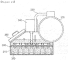
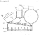
FIG. 17 is a state view schematically illustrating a state in which the mask is replaced in the cooling device andFIG. 18 is a view schematically illustrating a state in which the mask is detached from the cooling device. - Referring to
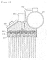
FIGS. 17 and18 , themask 330 may be provided to be detached from theactuator 340. That is, thefastening part 333 formed on thebase plate 331 and an action rod of theactuator 340 may be provided to be detached from each other. This is to easily replace only themask 330 when themask 330 may not accurately open and close thenozzle 320 due to the deformation of thebase plate 331 or corrosion of theelastic member 332 according to a use for long period of time. In this case, theactuator 340 and thefastening part 333 are fastened to each other by apin 360 as illustrated inFIG. 17 , such that theactuator 340 and thefastening part 333 may be more simply fastened to and separated from each other. Of course, the configuration for detaching theactuator 340 and thebase plate 331 from each other is not limited thereto, and various mechanical methods may be used. - To this end, the
housing 310 may further include apenetrating part 311 provided to be in communication with the outside and formed to have a size in which themask 330 may be pulled out or inserted, and adoor part 350 opening and closing the penetratingpart 311 of thehousing 310. That is, thedoor part 350 may close the penetratingpart 311 of thehousing 310, and may open the inside of thehousing 310 by opening thedoor part 350 when it is necessary to check an inside state of thehousing 310 or replace themask 330. In this case, thedoor part 350 may be provided to open and close the penetratingpart 311 by being rotatably fastened to thehousing 310, or to open and close the penetratingpart 311 by being provided to be detached from the penetratingpart 311. -
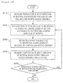
FIG. 19 is a flowchart schematically illustrating a cooling method according to an exemplary embodiment in the present disclosure. - Referring to
FIG. 19 , a cooling method may include a high-temperature material temperature measuring step (S110) of measuring a temperature in a width direction of a material which passes through a rolling mill and then enters a nozzle assembly, a spray flow rate setting step (S120) of dividing the material into predetermined zones in the width direction and setting flow rate of a cooling fluid to be sprayed to the respective divided zones according to the temperature in the width direction of the material, and a coolant spraying step (S130) of separately spraying the cooling fluid to the respective divided zones of the material by controlling the nozzle assembly in which a plurality of group nozzles are formed in line in the width direction of the material. - In addition, the cooling method may further include a cooled material temperature measuring step (S140) of measuring a temperature in the width direction of the material which passes through the nozzle assembly and is cooled, wherein when a temperature deviation in the width direction of the material measured in the cooled material temperature measuring step (S140) is higher than a predetermined temperature, that is, a temperature deviation range that the material has to satisfy (Yes in S150), a flow rate of the cooling fluid to be sprayed to the respective divided zones of the material may be again adjusted by returning to the spray flow rate setting step (S120) in consideration of the temperature deviation.
- According to the above-mentioned method, the flow rate of the cooling fluid sprayed to the respective zones may be primarily set through data measured from the high-temperature material temperature step (S110) online, and if the temperature deviation in the width direction of the material is more than the predetermined temperature through the data measured from the cooled material temperature measuring step (S140), the flow rate of the cooling fluid sprayed to the respective zones may be secondarily adjusted. Thereby, an optimal spray flow rate of the cooling fluid capable of significantly reducing the temperature deviation of the material may be set.
- Here, in the spray flow rate setting step (S120), to prevent an occurrence of water hammering in zones in which the cooling fluid is stored and supplied, a predetermined amount of cooling fluid may be set to be discharged through group nozzles positioned at both ends among the plurality of group nozzles.
- In addition, the nozzle assembly may be configured to selectively spray the cooling fluid to a specific zone in the width direction of the material by separately opening and closing the plurality of group nozzles.
- In addition, the nozzle assembly may be provided to control the plurality of group nozzles to be separately opened and closed, and may spray the flow rate of the cooling fluid sprayed in the width direction of the material to be different for each of the group nozzles.
- As described above, although the present disclosure has been described with reference to exemplary embodiments and the accompanying drawings, it would be appreciated by those skilled in the art that the present disclosure is not limited thereto, but various modifications and alterations might be made without departing from the scope defined in the following claims.
Claims (22)
- A cooling device comprising:a base frame connected to an external cooling fluid supplying line and disposed to spray a coolant to a material which is heated in a heating furnace and then passes through a rolling mill; anda nozzle assembly disposed on the base frame and spraying a cooling fluid to a plurality of zones, divided in a width direction of the material, in any pattern to significantly reduce a temperature deviation in the width direction of the material.
- The cooling device of claim 1, wherein the nozzle assembly is disposed on the base frame to be supplied with the cooling fluid,
nozzles are formed in a plurality of rows and columns, a predetermined number of nozzles form a group to be divided into a plurality of group nozzles, and
the group nozzles are opened and closed to spray the cooling fluid to predetermined zones. - The cooling device of claim 2, wherein the base frame is disposed above a moving material, and
the plurality of group nozzles of the nozzle assembly are disposed in line to be parallel to the width direction of the material. - The cooling device of claim 3, wherein the nozzle assembly selectively sprays the cooling fluid to a specific zone in the width direction of the material by separately opening and closing the plurality of group nozzles.
- The cooling device of claim 3, wherein the nozzle assembly is provided to spray a flow rate of the cooling fluid sprayed in the width direction of the material to be different for each of the group nozzles by controlling the plurality of group nozzles to be separately opened and closed.
- The cooling device of claim 2, wherein the nozzle assembly is provided to discharge a predetermined amount of cooling fluid through group nozzles positioned at both ends among the plurality of group nozzles to prevent an occurrence of water hammering in zones in which the cooling fluid is stored and supplied.
- The cooling device of claim 4, further comprising:a high-temperature material temperature sensor disposed upstream of the nozzle assembly and measuring a temperature in the width direction of the material which enters the nozzle assembly; anda controlling unit controlling the nozzle assembly to adjust a flow rate of the cooling fluid sprayed in the width direction of the material in response to temperature data in the width direction of the material received from the high-temperature material temperature sensor.
- The cooling device of claim 7, further comprising: a cooled material temperature sensor disposed downstream of the nozzle assembly and measuring a temperature in the width direction of the material passing through the nozzle assembly,
wherein the controlling unit controls the nozzle assembly by resetting the flow rate of the cooling fluid to be sprayed to the respective divided zones of the material in consideration of a temperature deviation when the temperature deviation in the width direction of the material received from the cooled material temperature sensor is higher than a predetermined temperature. - The cooling device of claim 1, wherein the base frame includes:a support frame provided with the nozzle assembly;a storage pipe disposed on the support frame and connected to the cooling fluid supplying line to store the cooling fluid; anda supply pipe connecting between the nozzle assembly and the storage pipe to supply the cooling fluid to the nozzle assembly.
- The cooling device of claim 2, wherein the nozzle assembly includes:a housing in which the cooling fluid is stored;the plurality of nozzles provided to protrude to the inside of the housing and having through holes formed in a length direction to spray the cooling fluid to the outside;a plurality of masks disposed on the plurality of group nozzles to open and close each of the group nozzles; anda plurality of actuators disposed on the housing and separately moving the plurality of masks in a vertical direction.
- The cooling device of claim 10, wherein the nozzle assembly controls a flow rate of the cooling fluid sprayed to the outside by adjusting an interval between the masks and the nozzles.
- The cooling device of claim 10, wherein the mask includes:a base plate in which a plurality of flow holes through which the cooling fluid flows are formed and having one side surface fastened to the actuator; andan elastic member disposed on the other side surface of the base plate, having holes formed in positions corresponding to the flow holes of the base plate, and sealing the through holes of the nozzles when the nozzles are closed.
- The cooling device of claim 12, wherein the base plate of the mask includes:a fastening part protruding from the center of one side surface thereof and fastened to the actuator; anda reinforcing rib extending from the fastening part to a circumference of the base plate to prevent a deformation of the base plate.
- The cooling device of claim 13, wherein the reinforcing rib includes:a plurality of first ribs extending from the fastening part to the respective corners of the base plate; andsecond ribs disposed on the plurality of first ribs and connecting between the plurality of first ribs.
- The cooling device of claim 12, wherein the elastic member further includes a protrusion protruding from a portion which is closely in contact with the nozzle and pressurizing and sealing the nozzle.
- The cooling device of claim 12, wherein the mask is provided to be detached from the actuator.
- The cooling device of claim 16, wherein the housing includes:a penetrating part provided to be in communication with the outside and formed to have a size appropriate for the mask to be pulled out or inserted; anda door part opening and closing the penetrating part of the housing.
- A cooling method, comprising:a high-temperature material temperature measuring step of measuring a temperature in a width direction of a material which passes through a rolling mill and then enters a nozzle assembly;a spray flow rate setting step of dividing the material into predetermined zones in the width direction and setting a flow rate of a cooling fluid to be sprayed to the respective divided zones according to the temperature in the width direction of the material; anda coolant spraying step of separately spraying the cooling fluid to the respective divided zones of the material by controlling the nozzle assembly in which a plurality of group nozzles are formed in line in the width direction of the material.
- The cooling method of claim 18, wherein in the spray flow rate setting step, to prevent an occurrence of water hammering in zones in which the cooling fluid is stored and supplied, a predetermined amount of cooling fluid is set to be discharged through group nozzles positioned at both ends among the plurality of group nozzles.
- The cooling method of claim 18, wherein the nozzle assembly selectively sprays the cooling fluid to a specific zone in the width direction of the material by separately opening and closing the plurality of group nozzles.
- The cooling method of claim 20, wherein the nozzle assembly is provided to control the plurality of group nozzles to be separately opened and closed, and sprays the flow rate of the cooling fluid sprayed in the width direction of the material to be different for each of the group nozzles.
- The cooling method of claim 18, further comprising a cooled material temperature measuring step of measuring a temperature in the width direction of the material which passes through the nozzle assembly and is cooled,
wherein when a temperature deviation in the width direction of the material measured in the cooled material temperature measuring step is higher than a predetermined temperature, a flow rate of the cooling fluid to be sprayed to the respective divided zones of the material is again set in the spray flow rate setting step in consideration of the temperature deviation.
Applications Claiming Priority (2)
| Application Number | Priority Date | Filing Date | Title |
|---|---|---|---|
| KR1020150184745A KR101746985B1 (en) | 2015-12-23 | 2015-12-23 | Cooling apparatus and method |
| PCT/KR2016/008206 WO2017111242A1 (en) | 2015-12-23 | 2016-07-27 | Cooling device and cooling method |
Publications (3)
| Publication Number | Publication Date |
|---|---|
| EP3395462A1 true EP3395462A1 (en) | 2018-10-31 |
| EP3395462A4 EP3395462A4 (en) | 2019-01-23 |
| EP3395462B1 EP3395462B1 (en) | 2020-07-15 |
Family
ID=59090609
Family Applications (1)
| Application Number | Title | Priority Date | Filing Date |
|---|---|---|---|
| EP16879110.1A Active EP3395462B1 (en) | 2015-12-23 | 2016-07-27 | Cooling device and cooling method |
Country Status (6)
| Country | Link |
|---|---|
| US (1) | US10967410B2 (en) |
| EP (1) | EP3395462B1 (en) |
| JP (1) | JP6650521B2 (en) |
| KR (1) | KR101746985B1 (en) |
| CN (2) | CN108472702A (en) |
| WO (1) | WO2017111242A1 (en) |
Families Citing this family (6)
| Publication number | Priority date | Publication date | Assignee | Title |
|---|---|---|---|---|
| KR101746985B1 (en) * | 2015-12-23 | 2017-06-14 | 주식회사 포스코 | Cooling apparatus and method |
| KR102390012B1 (en) * | 2020-06-09 | 2022-04-28 | 제일산기 주식회사 | The cooling apparatus of hot briquetted iron |
| KR102364700B1 (en) * | 2020-09-25 | 2022-02-18 | 현대제철 주식회사 | Apparatus and method for preventing over-cooling of steel sheet edge |
| CN115716090B (en) * | 2021-08-27 | 2026-01-20 | 宝山钢铁股份有限公司 | Hot rolling laminar cooling method |
| CN113758113B (en) * | 2021-09-23 | 2022-09-13 | 成都流体动力创新中心 | Cooling system, device and method for electromagnetic suspension device of vacuum pipeline magnetic suspension train |
| CN117655112B (en) * | 2023-12-19 | 2024-12-20 | 江西联瑞新材料科技有限公司 | Rolling mill thermal imaging plate shape control method |
Family Cites Families (25)
| Publication number | Priority date | Publication date | Assignee | Title |
|---|---|---|---|---|
| JPS5848019B2 (en) * | 1979-11-09 | 1983-10-26 | 石川島播磨重工業株式会社 | Spray cooling method and device for steel plate |
| JPS60174833A (en) * | 1984-02-20 | 1985-09-09 | Nippon Steel Corp | Cooling method of hot steel sheet |
| JP2610019B2 (en) * | 1986-07-03 | 1997-05-14 | 新日本製鐵株式会社 | Cooling method of hot steel plate |
| KR100241018B1 (en) * | 1995-12-28 | 2000-03-02 | 이구택 | Flow control method and device for laminar flow cooling |
| KR200414939Y1 (en) * | 2006-01-25 | 2006-04-28 | 김오수 | Roller scraper of rolling mill |
| EP2058060B1 (en) * | 2007-05-11 | 2014-09-17 | Nippon Steel & Sumitomo Metal Corporation | Apparatus, and method, for controlled cooling of steel sheet |
| DE102007053523A1 (en) * | 2007-05-30 | 2008-12-04 | Sms Demag Ag | Device for influencing temperature distribution over width of slab or strip, particularly in one or multiple hot strip mill, has cooling device, which is provided with nozzles for applying cooling agent on slab or strip |
| FI20070622L (en) * | 2007-08-17 | 2009-04-15 | Outokumpu Oy | Method and device for checking evenness during cooling of a strip made of stainless steel |
| CN201287148Y (en) * | 2008-05-06 | 2009-08-12 | 首钢总公司 | Medium and heavy plate control cooling device |
| CN201291227Y (en) * | 2008-09-04 | 2009-08-19 | 唐山钢铁股份有限公司 | Water cooling device for producing niobium micro-alloyed steel by tandem rolling middle thin slab |
| CN101507980B (en) * | 2009-03-24 | 2012-06-13 | 中冶南方工程技术有限公司 | Controlled cooling system of medium and heavy plate after rolling |
| CN102189132A (en) * | 2010-03-19 | 2011-09-21 | 宝山钢铁股份有限公司 | Upper spray cooling device arranged among finishing mill racks |
| CN102189127B (en) * | 2010-03-19 | 2013-04-03 | 宝山钢铁股份有限公司 | Upper spraying cooling device arranged between frames of finishing mill |
| KR20120053744A (en) | 2010-11-18 | 2012-05-29 | 주식회사 포스코 | Apparatus for cooling cast piece in continuous casting process |
| KR101330871B1 (en) * | 2011-10-28 | 2013-11-18 | 현대제철 주식회사 | Cooling device for rolling mill |
| KR101326824B1 (en) | 2011-11-07 | 2013-11-11 | 현대자동차주식회사 | Mold for hot stamping strip masking |
| CN104024817B (en) * | 2011-12-28 | 2016-09-07 | Posco公司 | Sensor device and include its capability evaluating device of cooling device |
| CN202683627U (en) * | 2012-04-19 | 2013-01-23 | 大连汇程铝业有限公司 | Cooling device for intermediate slab rolled by aluminum hot roughing mill |
| KR101399879B1 (en) * | 2012-09-27 | 2014-05-27 | 현대제철 주식회사 | Cooling apparatus for material |
| KR101490622B1 (en) | 2013-10-01 | 2015-02-05 | 주식회사 포스코 | Hot plate cooling adjustable apparatus |
| CN104741389B (en) * | 2013-12-25 | 2016-08-24 | 宝山钢铁股份有限公司 | A kind of by changing the method that cooling water jet width controls hot-strip glacing flatness |
| CN203737734U (en) * | 2014-03-11 | 2014-07-30 | 邯钢集团邯宝钢铁有限公司 | Interstand cooling manifold with low probability of blocking of spray pipes |
| KR101557725B1 (en) | 2014-07-21 | 2015-10-06 | 주식회사 포스코 | Movable apparatus for cooling hot plate |
| CN204429864U (en) * | 2014-12-23 | 2015-07-01 | 江苏东方成套设备制造有限公司 | A kind of novel valve snail roller repairing device |
| KR101746985B1 (en) * | 2015-12-23 | 2017-06-14 | 주식회사 포스코 | Cooling apparatus and method |
-
2015
- 2015-12-23 KR KR1020150184745A patent/KR101746985B1/en active Active
-
2016
- 2016-07-27 CN CN201680075542.2A patent/CN108472702A/en active Pending
- 2016-07-27 JP JP2018532101A patent/JP6650521B2/en active Active
- 2016-07-27 US US16/064,440 patent/US10967410B2/en active Active
- 2016-07-27 EP EP16879110.1A patent/EP3395462B1/en active Active
- 2016-07-27 CN CN202010539801.0A patent/CN111744975A/en active Pending
- 2016-07-27 WO PCT/KR2016/008206 patent/WO2017111242A1/en not_active Ceased
Also Published As
| Publication number | Publication date |
|---|---|
| EP3395462A4 (en) | 2019-01-23 |
| CN108472702A (en) | 2018-08-31 |
| US10967410B2 (en) | 2021-04-06 |
| JP6650521B2 (en) | 2020-02-19 |
| KR101746985B1 (en) | 2017-06-14 |
| EP3395462B1 (en) | 2020-07-15 |
| JP2018538146A (en) | 2018-12-27 |
| WO2017111242A1 (en) | 2017-06-29 |
| CN111744975A (en) | 2020-10-09 |
| US20190001385A1 (en) | 2019-01-03 |
Similar Documents
| Publication | Publication Date | Title |
|---|---|---|
| EP3395462B1 (en) | Cooling device and cooling method | |
| US10994316B2 (en) | Straightening system and straightening method | |
| EP3603833B1 (en) | Device and method for cooling hot-rolled steel sheet | |
| KR101625810B1 (en) | Nozzle header, cooling device, device for producing hot-rolled steel sheet, and method for producing hot-rolled steel sheet | |
| KR101767774B1 (en) | Cooling apparatus | |
| KR101746984B1 (en) | Cooling system and method | |
| JP2009274101A (en) | Control method and control device for roll coolant in foil rolling machine | |
| KR101003202B1 (en) | Steel plate chiller | |
| KR100529055B1 (en) | Device for cooling strip in continuous annealing furnace | |
| KR101404054B1 (en) | Apparatus for spray nozzle with block type | |
| KR101758519B1 (en) | Correcting system and method | |
| JP5332772B2 (en) | Steel cooling device and cooling method | |
| JP2010214433A (en) | Apparatus and method for cooling steel | |
| JPS59137111A (en) | Hot steel plate cooling device | |
| KR102020437B1 (en) | Cooling Device and Hot Rolling Equipment | |
| KR100758486B1 (en) | Width Rolling Roll Cooling System for Rolled Materials | |
| JP4333406B2 (en) | Method and apparatus for cooling hot-rolled metal strip | |
| KR20140078280A (en) | Apparatus for spray nozzle with socket type | |
| CZ2013131A3 (en) | Apparatus for cooling extruded or rolled metal sections | |
| JPH07197116A (en) | Fluid supply device |
Legal Events
| Date | Code | Title | Description |
|---|---|---|---|
| STAA | Information on the status of an ep patent application or granted ep patent |
Free format text: STATUS: THE INTERNATIONAL PUBLICATION HAS BEEN MADE |
|
| PUAI | Public reference made under article 153(3) epc to a published international application that has entered the european phase |
Free format text: ORIGINAL CODE: 0009012 |
|
| STAA | Information on the status of an ep patent application or granted ep patent |
Free format text: STATUS: REQUEST FOR EXAMINATION WAS MADE |
|
| 17P | Request for examination filed |
Effective date: 20180720 |
|
| AK | Designated contracting states |
Kind code of ref document: A1 Designated state(s): AL AT BE BG CH CY CZ DE DK EE ES FI FR GB GR HR HU IE IS IT LI LT LU LV MC MK MT NL NO PL PT RO RS SE SI SK SM TR |
|
| AX | Request for extension of the european patent |
Extension state: BA ME |
|
| A4 | Supplementary search report drawn up and despatched |
Effective date: 20181220 |
|
| RIC1 | Information provided on ipc code assigned before grant |
Ipc: B21B 45/02 20060101AFI20181214BHEP |
|
| DAV | Request for validation of the european patent (deleted) | ||
| DAX | Request for extension of the european patent (deleted) | ||
| GRAP | Despatch of communication of intention to grant a patent |
Free format text: ORIGINAL CODE: EPIDOSNIGR1 |
|
| STAA | Information on the status of an ep patent application or granted ep patent |
Free format text: STATUS: GRANT OF PATENT IS INTENDED |
|
| INTG | Intention to grant announced |
Effective date: 20200115 |
|
| GRAJ | Information related to disapproval of communication of intention to grant by the applicant or resumption of examination proceedings by the epo deleted |
Free format text: ORIGINAL CODE: EPIDOSDIGR1 |
|
| STAA | Information on the status of an ep patent application or granted ep patent |
Free format text: STATUS: REQUEST FOR EXAMINATION WAS MADE |
|
| GRAP | Despatch of communication of intention to grant a patent |
Free format text: ORIGINAL CODE: EPIDOSNIGR1 |
|
| STAA | Information on the status of an ep patent application or granted ep patent |
Free format text: STATUS: GRANT OF PATENT IS INTENDED |
|
| INTC | Intention to grant announced (deleted) | ||
| INTG | Intention to grant announced |
Effective date: 20200504 |
|
| RAP1 | Party data changed (applicant data changed or rights of an application transferred) |
Owner name: POSCO |
|
| GRAS | Grant fee paid |
Free format text: ORIGINAL CODE: EPIDOSNIGR3 |
|
| GRAA | (expected) grant |
Free format text: ORIGINAL CODE: 0009210 |
|
| STAA | Information on the status of an ep patent application or granted ep patent |
Free format text: STATUS: THE PATENT HAS BEEN GRANTED |
|
| AK | Designated contracting states |
Kind code of ref document: B1 Designated state(s): AL AT BE BG CH CY CZ DE DK EE ES FI FR GB GR HR HU IE IS IT LI LT LU LV MC MK MT NL NO PL PT RO RS SE SI SK SM TR |
|
| REG | Reference to a national code |
Ref country code: CH Ref legal event code: EP Ref country code: GB Ref legal event code: FG4D |
|
| REG | Reference to a national code |
Ref country code: DE Ref legal event code: R096 Ref document number: 602016040208 Country of ref document: DE |
|
| REG | Reference to a national code |
Ref country code: IE Ref legal event code: FG4D |
|
| REG | Reference to a national code |
Ref country code: AT Ref legal event code: REF Ref document number: 1290415 Country of ref document: AT Kind code of ref document: T Effective date: 20200815 |
|
| REG | Reference to a national code |
Ref country code: SE Ref legal event code: TRGR |
|
| REG | Reference to a national code |
Ref country code: LT Ref legal event code: MG4D |
|
| REG | Reference to a national code |
Ref country code: AT Ref legal event code: MK05 Ref document number: 1290415 Country of ref document: AT Kind code of ref document: T Effective date: 20200715 |
|
| REG | Reference to a national code |
Ref country code: NL Ref legal event code: MP Effective date: 20200715 |
|
| PG25 | Lapsed in a contracting state [announced via postgrant information from national office to epo] |
Ref country code: FI Free format text: LAPSE BECAUSE OF FAILURE TO SUBMIT A TRANSLATION OF THE DESCRIPTION OR TO PAY THE FEE WITHIN THE PRESCRIBED TIME-LIMIT Effective date: 20200715 Ref country code: HR Free format text: LAPSE BECAUSE OF FAILURE TO SUBMIT A TRANSLATION OF THE DESCRIPTION OR TO PAY THE FEE WITHIN THE PRESCRIBED TIME-LIMIT Effective date: 20200715 Ref country code: GR Free format text: LAPSE BECAUSE OF FAILURE TO SUBMIT A TRANSLATION OF THE DESCRIPTION OR TO PAY THE FEE WITHIN THE PRESCRIBED TIME-LIMIT Effective date: 20201016 Ref country code: NO Free format text: LAPSE BECAUSE OF FAILURE TO SUBMIT A TRANSLATION OF THE DESCRIPTION OR TO PAY THE FEE WITHIN THE PRESCRIBED TIME-LIMIT Effective date: 20201015 Ref country code: BG Free format text: LAPSE BECAUSE OF FAILURE TO SUBMIT A TRANSLATION OF THE DESCRIPTION OR TO PAY THE FEE WITHIN THE PRESCRIBED TIME-LIMIT Effective date: 20201015 Ref country code: PT Free format text: LAPSE BECAUSE OF FAILURE TO SUBMIT A TRANSLATION OF THE DESCRIPTION OR TO PAY THE FEE WITHIN THE PRESCRIBED TIME-LIMIT Effective date: 20201116 Ref country code: LT Free format text: LAPSE BECAUSE OF FAILURE TO SUBMIT A TRANSLATION OF THE DESCRIPTION OR TO PAY THE FEE WITHIN THE PRESCRIBED TIME-LIMIT Effective date: 20200715 Ref country code: ES Free format text: LAPSE BECAUSE OF FAILURE TO SUBMIT A TRANSLATION OF THE DESCRIPTION OR TO PAY THE FEE WITHIN THE PRESCRIBED TIME-LIMIT Effective date: 20200715 Ref country code: AT Free format text: LAPSE BECAUSE OF FAILURE TO SUBMIT A TRANSLATION OF THE DESCRIPTION OR TO PAY THE FEE WITHIN THE PRESCRIBED TIME-LIMIT Effective date: 20200715 |
|
| PG25 | Lapsed in a contracting state [announced via postgrant information from national office to epo] |
Ref country code: PL Free format text: LAPSE BECAUSE OF FAILURE TO SUBMIT A TRANSLATION OF THE DESCRIPTION OR TO PAY THE FEE WITHIN THE PRESCRIBED TIME-LIMIT Effective date: 20200715 Ref country code: RS Free format text: LAPSE BECAUSE OF FAILURE TO SUBMIT A TRANSLATION OF THE DESCRIPTION OR TO PAY THE FEE WITHIN THE PRESCRIBED TIME-LIMIT Effective date: 20200715 Ref country code: LV Free format text: LAPSE BECAUSE OF FAILURE TO SUBMIT A TRANSLATION OF THE DESCRIPTION OR TO PAY THE FEE WITHIN THE PRESCRIBED TIME-LIMIT Effective date: 20200715 Ref country code: IS Free format text: LAPSE BECAUSE OF FAILURE TO SUBMIT A TRANSLATION OF THE DESCRIPTION OR TO PAY THE FEE WITHIN THE PRESCRIBED TIME-LIMIT Effective date: 20201115 |
|
| REG | Reference to a national code |
Ref country code: CH Ref legal event code: PL |
|
| PG25 | Lapsed in a contracting state [announced via postgrant information from national office to epo] |
Ref country code: NL Free format text: LAPSE BECAUSE OF FAILURE TO SUBMIT A TRANSLATION OF THE DESCRIPTION OR TO PAY THE FEE WITHIN THE PRESCRIBED TIME-LIMIT Effective date: 20200715 |
|
| REG | Reference to a national code |
Ref country code: DE Ref legal event code: R097 Ref document number: 602016040208 Country of ref document: DE |
|
| REG | Reference to a national code |
Ref country code: BE Ref legal event code: MM Effective date: 20200731 |
|
| PG25 | Lapsed in a contracting state [announced via postgrant information from national office to epo] |
Ref country code: LU Free format text: LAPSE BECAUSE OF NON-PAYMENT OF DUE FEES Effective date: 20200727 Ref country code: LI Free format text: LAPSE BECAUSE OF NON-PAYMENT OF DUE FEES Effective date: 20200731 Ref country code: DK Free format text: LAPSE BECAUSE OF FAILURE TO SUBMIT A TRANSLATION OF THE DESCRIPTION OR TO PAY THE FEE WITHIN THE PRESCRIBED TIME-LIMIT Effective date: 20200715 Ref country code: CH Free format text: LAPSE BECAUSE OF NON-PAYMENT OF DUE FEES Effective date: 20200731 Ref country code: CZ Free format text: LAPSE BECAUSE OF FAILURE TO SUBMIT A TRANSLATION OF THE DESCRIPTION OR TO PAY THE FEE WITHIN THE PRESCRIBED TIME-LIMIT Effective date: 20200715 Ref country code: RO Free format text: LAPSE BECAUSE OF FAILURE TO SUBMIT A TRANSLATION OF THE DESCRIPTION OR TO PAY THE FEE WITHIN THE PRESCRIBED TIME-LIMIT Effective date: 20200715 Ref country code: EE Free format text: LAPSE BECAUSE OF FAILURE TO SUBMIT A TRANSLATION OF THE DESCRIPTION OR TO PAY THE FEE WITHIN THE PRESCRIBED TIME-LIMIT Effective date: 20200715 Ref country code: IT Free format text: LAPSE BECAUSE OF FAILURE TO SUBMIT A TRANSLATION OF THE DESCRIPTION OR TO PAY THE FEE WITHIN THE PRESCRIBED TIME-LIMIT Effective date: 20200715 Ref country code: SM Free format text: LAPSE BECAUSE OF FAILURE TO SUBMIT A TRANSLATION OF THE DESCRIPTION OR TO PAY THE FEE WITHIN THE PRESCRIBED TIME-LIMIT Effective date: 20200715 |
|
| PLBE | No opposition filed within time limit |
Free format text: ORIGINAL CODE: 0009261 |
|
| STAA | Information on the status of an ep patent application or granted ep patent |
Free format text: STATUS: NO OPPOSITION FILED WITHIN TIME LIMIT |
|
| PG25 | Lapsed in a contracting state [announced via postgrant information from national office to epo] |
Ref country code: BE Free format text: LAPSE BECAUSE OF NON-PAYMENT OF DUE FEES Effective date: 20200731 Ref country code: AL Free format text: LAPSE BECAUSE OF FAILURE TO SUBMIT A TRANSLATION OF THE DESCRIPTION OR TO PAY THE FEE WITHIN THE PRESCRIBED TIME-LIMIT Effective date: 20200715 |
|
| 26N | No opposition filed |
Effective date: 20210416 |
|
| GBPC | Gb: european patent ceased through non-payment of renewal fee |
Effective date: 20201015 |
|
| PG25 | Lapsed in a contracting state [announced via postgrant information from national office to epo] |
Ref country code: SK Free format text: LAPSE BECAUSE OF FAILURE TO SUBMIT A TRANSLATION OF THE DESCRIPTION OR TO PAY THE FEE WITHIN THE PRESCRIBED TIME-LIMIT Effective date: 20200715 |
|
| PG25 | Lapsed in a contracting state [announced via postgrant information from national office to epo] |
Ref country code: SI Free format text: LAPSE BECAUSE OF FAILURE TO SUBMIT A TRANSLATION OF THE DESCRIPTION OR TO PAY THE FEE WITHIN THE PRESCRIBED TIME-LIMIT Effective date: 20200715 Ref country code: GB Free format text: LAPSE BECAUSE OF NON-PAYMENT OF DUE FEES Effective date: 20201015 Ref country code: IE Free format text: LAPSE BECAUSE OF NON-PAYMENT OF DUE FEES Effective date: 20200727 |
|
| PG25 | Lapsed in a contracting state [announced via postgrant information from national office to epo] |
Ref country code: TR Free format text: LAPSE BECAUSE OF FAILURE TO SUBMIT A TRANSLATION OF THE DESCRIPTION OR TO PAY THE FEE WITHIN THE PRESCRIBED TIME-LIMIT Effective date: 20200715 Ref country code: MT Free format text: LAPSE BECAUSE OF FAILURE TO SUBMIT A TRANSLATION OF THE DESCRIPTION OR TO PAY THE FEE WITHIN THE PRESCRIBED TIME-LIMIT Effective date: 20200715 Ref country code: CY Free format text: LAPSE BECAUSE OF FAILURE TO SUBMIT A TRANSLATION OF THE DESCRIPTION OR TO PAY THE FEE WITHIN THE PRESCRIBED TIME-LIMIT Effective date: 20200715 |
|
| PG25 | Lapsed in a contracting state [announced via postgrant information from national office to epo] |
Ref country code: MK Free format text: LAPSE BECAUSE OF FAILURE TO SUBMIT A TRANSLATION OF THE DESCRIPTION OR TO PAY THE FEE WITHIN THE PRESCRIBED TIME-LIMIT Effective date: 20200715 Ref country code: MC Free format text: LAPSE BECAUSE OF FAILURE TO SUBMIT A TRANSLATION OF THE DESCRIPTION OR TO PAY THE FEE WITHIN THE PRESCRIBED TIME-LIMIT Effective date: 20200715 |
|
| REG | Reference to a national code |
Ref country code: DE Ref legal event code: R081 Ref document number: 602016040208 Country of ref document: DE Owner name: POSCO CO., LTD, POHANG-SI, KR Free format text: FORMER OWNER: POSCO, POHANG-SI, KYUNGSANGBOOK-DO, KR Ref country code: DE Ref legal event code: R081 Ref document number: 602016040208 Country of ref document: DE Owner name: POSCO CO., LTD, POHANG- SI, KR Free format text: FORMER OWNER: POSCO, POHANG-SI, KYUNGSANGBOOK-DO, KR Ref country code: DE Ref legal event code: R081 Ref document number: 602016040208 Country of ref document: DE Owner name: POSCO HOLDINGS INC., KR Free format text: FORMER OWNER: POSCO, POHANG-SI, KYUNGSANGBOOK-DO, KR |
|
| REG | Reference to a national code |
Ref country code: DE Ref legal event code: R081 Ref document number: 602016040208 Country of ref document: DE Owner name: POSCO CO., LTD, POHANG-SI, KR Free format text: FORMER OWNER: POSCO HOLDINGS INC., SEOUL, KR Ref country code: DE Ref legal event code: R081 Ref document number: 602016040208 Country of ref document: DE Owner name: POSCO CO., LTD, POHANG- SI, KR Free format text: FORMER OWNER: POSCO HOLDINGS INC., SEOUL, KR |
|
| PGFP | Annual fee paid to national office [announced via postgrant information from national office to epo] |
Ref country code: FR Payment date: 20250624 Year of fee payment: 10 |
|
| PGFP | Annual fee paid to national office [announced via postgrant information from national office to epo] |
Ref country code: SE Payment date: 20250624 Year of fee payment: 10 |
|
| PGFP | Annual fee paid to national office [announced via postgrant information from national office to epo] |
Ref country code: DE Payment date: 20250624 Year of fee payment: 10 |