EP3394670B1 - Elektromagnetischer frequenzumrichter - Google Patents
Elektromagnetischer frequenzumrichter Download PDFInfo
- Publication number
- EP3394670B1 EP3394670B1 EP16823030.8A EP16823030A EP3394670B1 EP 3394670 B1 EP3394670 B1 EP 3394670B1 EP 16823030 A EP16823030 A EP 16823030A EP 3394670 B1 EP3394670 B1 EP 3394670B1
- Authority
- EP
- European Patent Office
- Prior art keywords
- atomic
- electromagnetic radiation
- frequency
- thz
- sources
- Prior art date
- Legal status (The legal status is an assumption and is not a legal conclusion. Google has not performed a legal analysis and makes no representation as to the accuracy of the status listed.)
- Active
Links
Images


Classifications
-
- G—PHYSICS
- G02—OPTICS
- G02F—OPTICAL DEVICES OR ARRANGEMENTS FOR THE CONTROL OF LIGHT BY MODIFICATION OF THE OPTICAL PROPERTIES OF THE MEDIA OF THE ELEMENTS INVOLVED THEREIN; NON-LINEAR OPTICS; FREQUENCY-CHANGING OF LIGHT; OPTICAL LOGIC ELEMENTS; OPTICAL ANALOGUE/DIGITAL CONVERTERS
- G02F1/00—Devices or arrangements for the control of the intensity, colour, phase, polarisation or direction of light arriving from an independent light source, e.g. switching, gating or modulating; Non-linear optics
- G02F1/35—Non-linear optics
- G02F1/353—Frequency conversion, i.e. wherein a light beam is generated with frequency components different from those of the incident light beams
- G02F1/3536—Four-wave interaction
-
- G—PHYSICS
- G02—OPTICS
- G02F—OPTICAL DEVICES OR ARRANGEMENTS FOR THE CONTROL OF LIGHT BY MODIFICATION OF THE OPTICAL PROPERTIES OF THE MEDIA OF THE ELEMENTS INVOLVED THEREIN; NON-LINEAR OPTICS; FREQUENCY-CHANGING OF LIGHT; OPTICAL LOGIC ELEMENTS; OPTICAL ANALOGUE/DIGITAL CONVERTERS
- G02F1/00—Devices or arrangements for the control of the intensity, colour, phase, polarisation or direction of light arriving from an independent light source, e.g. switching, gating or modulating; Non-linear optics
- G02F1/35—Non-linear optics
- G02F1/353—Frequency conversion, i.e. wherein a light beam is generated with frequency components different from those of the incident light beams
-
- G—PHYSICS
- G02—OPTICS
- G02F—OPTICAL DEVICES OR ARRANGEMENTS FOR THE CONTROL OF LIGHT BY MODIFICATION OF THE OPTICAL PROPERTIES OF THE MEDIA OF THE ELEMENTS INVOLVED THEREIN; NON-LINEAR OPTICS; FREQUENCY-CHANGING OF LIGHT; OPTICAL LOGIC ELEMENTS; OPTICAL ANALOGUE/DIGITAL CONVERTERS
- G02F2201/00—Constructional arrangements not provided for in groups G02F1/00 - G02F7/00
- G02F2201/05—Constructional arrangements not provided for in groups G02F1/00 - G02F7/00 multimode
-
- G—PHYSICS
- G02—OPTICS
- G02F—OPTICAL DEVICES OR ARRANGEMENTS FOR THE CONTROL OF LIGHT BY MODIFICATION OF THE OPTICAL PROPERTIES OF THE MEDIA OF THE ELEMENTS INVOLVED THEREIN; NON-LINEAR OPTICS; FREQUENCY-CHANGING OF LIGHT; OPTICAL LOGIC ELEMENTS; OPTICAL ANALOGUE/DIGITAL CONVERTERS
- G02F2203/00—Function characteristic
- G02F2203/13—Function characteristic involving THZ radiation
-
- G—PHYSICS
- G02—OPTICS
- G02F—OPTICAL DEVICES OR ARRANGEMENTS FOR THE CONTROL OF LIGHT BY MODIFICATION OF THE OPTICAL PROPERTIES OF THE MEDIA OF THE ELEMENTS INVOLVED THEREIN; NON-LINEAR OPTICS; FREQUENCY-CHANGING OF LIGHT; OPTICAL LOGIC ELEMENTS; OPTICAL ANALOGUE/DIGITAL CONVERTERS
- G02F2203/00—Function characteristic
- G02F2203/21—Thermal instability, i.e. DC drift, of an optical modulator; Arrangements or methods for the reduction thereof
Definitions
- This invention relates to an electromagnetic frequency converter in particular to a microwave to optical converter.
- microwaves are conveniently used in electronic devices and quantum information processing systems owing to their strong non-linear coupling, while optical frequencies are conveniently used for the transmission of information owing to the long distances that such information can be transmitted with very high information density while suffering negligible thermal noise at room temperature (optical frequencies are good carriers for data).
- Patric Ackermann et al. "Strong quantum interference in frequency up-conversion towards short vacuum-ultraviolet radiation pulses", Physical Review A (Atomic, Molecular and Optical Physics), vol. 89, no.6, 1 June 2014 discloses experimental data on quantum interferences in resonantly enhanced frequency up-conversion towards the vacuum-ultraviolet spectral regime. The process is driven in xenon atoms by ultrashort (picosecond) laser pulses and uses two simultaneous frequency conversion pathways via an excited intermediate state.
- the aim of the present invention is to provide an improved device for converting between different electromagnetic frequencies.
- the invention When viewed from a first aspect the invention provides an electromagnetic frequency converter for converting input electromagnetic radiation to output electromagnetic radiation of a different frequency, the electromagnetic frequency converter comprising:
- the invention When viewed from a second aspect the invention provides a method of converting input electromagnetic radiation to output electromagnetic radiation of a different frequency, the method comprising:
- the present invention therefore provides a frequency converter for converting electromagnetic radiation of one frequency that is input into the converter into electromagnetic radiation of a different frequency that is output from the converter.
- the converter includes an atomic ensemble that is used to perform the conversion between the different frequencies, with the atomic ensemble being driven by at least two sources of electromagnetic radiation to put the atomic ensemble into an, e.g. coherent, superposition of states, such that the conversion is performed, as will be described.
- the atomic ensemble is arranged to have incident upon it electromagnetic radiation from at least two different sources, with each source providing electromagnetic radiation having a frequency selected from a set of possible atomic transition frequencies for the atomic valence electrons in the atomic ensemble.
- the one or more first sources input electromagnetic radiation having a summed frequency of between 600 THz and 1500 THz.
- the one or more second sources input electromagnetic radiation having a summed frequency of between 300 THz and 750 THz.
- the one or more first sources are arranged to excite atomic valence electrons in the atomic ensemble from their ground state to a first highly excited Rydberg state.
- the one or more second sources are arranged to excite atomic valence electrons in the atomic ensemble from an excited state to a second highly excited Rydberg state.
- the excited state is linked to the ground state by an atomic transition having a frequency between 193 THz and 800 THz for the atomic valence electrons in the atomic ensemble.
- the second Rydberg state is linked to the lower, first Rydberg state by an atomic transition having a frequency between 300 MHz and 3 THz for the atomic valence electrons in the atomic ensemble.
- electromagnetic radiation having a frequency between 193 THz and 800 THz i.e. optical or near-infrared radiation
- electromagnetic radiation having a frequency between 300 MHz and 3 THz i.e. microwave or terahertz radiation
- the incident radiation is converted from an optical (or near-infrared) frequency to a microwave (or terahertz) frequency or vice versa.
- microwave or terahertz radiation between 300 MHz and 3 THz
- the electromagnetic frequency converter of the present invention links the manifold of highly excited Rydberg states of the atomic ensemble (between which microwave or terahertz frequency atomic transitions are present) and the lower lying optical or near-infrared atomic transitions of the atomic ensemble, in order to convert microwave or terahertz radiation into optical or near-infrared radiation (or vice versa).
- the Rydberg states are highly excited and thus close to the ionisation potential of the atoms in the atomic ensemble.
- the valence electrons in these Rydberg states have a very large orbit, very far out from the nucleus and the other non-valence electrons. Therefore the atomic ensemble, when prepared in this way, contains many (e.g. identical) large electric dipoles that couple strongly to microwave or terahertz radiation and therefore there is a relatively high probability that the incident microwave or terahertz radiation will be absorbed by one of the many atomic transitions in the Rydberg manifold of states.
- the atoms in the Rydberg states and the atoms in the ground state may therefore be driven by respective external fields (the one or more second sources of, e.g. optical or near-infrared, radiation and the one or more first sources of, e.g. optical or near-infrared, radiation) to link the excited state with the Rydberg states, to produce a large collective response, thus providing an efficient mechanism for frequency conversion.
- the one or more second sources of, e.g. optical or near-infrared, radiation and the one or more first sources of, e.g. optical or near-infrared, radiation to link the excited state with the Rydberg states, to produce a large collective response, thus providing an efficient mechanism for frequency conversion.
- the decay rates of the Rydberg states are relatively small owing to the small overlap of the wavefunction of these states with the wavefunction of low lying electronic states. This means that the lifetime, and thus coherence time, of the Rydberg states is relatively long, which increases the efficiency of the conversions. For example, the lifetime of some of the Rydberg states is approximately 10 ⁇ s to 100 ⁇ s, which can be several hundred times longer than the lifetime of the low-lying excited state.
- the converter of the present invention does not need to use a cavity, as has been necessary in existing converters. As no cavity is required in the converter of the present invention, the bandwidth available for conversion frequencies can be much larger.
- the converter of the present invention preferably does not require any optical pumping (e.g. in addition to the electromagnetic radiation from the one or more first and one or more second third sources) because the highly excited Rydberg states are not thermally populated (e.g. at room temperature) so there is very little, if any, thermal noise to suppress and therefore no need for optical pumping to keep these states empty.
- the converter also does not require any micro-fabrication of components because the active component of the converter is simply a volume of atoms to which radiation is applied.
- the one or more first sources of electromagnetic radiation may comprise any suitable and desired number of sources of electromagnetic radiation that are arranged to be incident upon the atomic assembly in order to excite atomic valence electrons in the atomic ensemble from the ground state to the first Rydberg state. Furthermore the one or more first sources of electromagnetic radiation may be arranged to be incident upon the atomic assembly in order to excite atomic valence electrons in the atomic ensemble from the ground state to the first Rydberg state using atomic transitions via any number of intermediate atomic states. Preferably the one or more first sources are arranged to excite atomic valence electrons via three or fewer intermediate atomic states, e.g. two or fewer, e.g. (and preferably) via a single intermediate atomic state. It is also envisaged that any individual source of electromagnetic radiation may be arranged to be used to excite atomic valence electrons between a plurality of different atomic states (i.e. preferably having transitions of similar frequencies).
- the one or more first sources of electromagnetic radiation are arranged to excite atomic valence electrons in the atomic ensemble from the ground state to the first Rydberg state via an, e.g. single, intermediate excited state, preferably such that the two atomic transitions (from the ground state to the intermediate excited state and then to the first Rydberg state) each have a frequency (selected from a set of possible atomic transition frequencies for the atomic valence electrons in the atomic ensemble) between 193 THz and 800 THz, i.e. the transitions are preferably both optical or near-infrared transitions.
- the electromagnetic frequency converter in this way, i.e. to excite the atomic valence electrons using the one or more first sources of electromagnetic radiation from the ground state to the first Rydberg state via an (e.g. single) intermediate excited state (i.e. which is higher than the ground state and lower than the first Rydberg state) helps to reduce the time taken to populate the first Rydberg state, owing to the generally high strength of the atomic transition between the ground state and the intermediate excited state (thus preferably the intermediate state used (and thus also the frequencies of the one or more first sources) is preferably chosen to have a relatively strong transition to the ground state).
- the intermediate excited state helps to create a coherence relatively quickly between the ground state and the first Rydberg state owing to the relatively short lifetime of the intermediate excited state (particularly compared to the relatively long lifetime of the first Rydberg state).
- the relatively high strength of the atomic transition between the ground state and the intermediate excited state helps to allow a lower power source to be used to excite the atomic valence electrons from the ground state to the intermediate excited state.
- the one or more first sources of electromagnetic radiation comprise:
- two or more, e.g. optical or near-infrared, atomic transitions are used to populate the first Rydberg state via the intermediate excited state (and preferably via no other intermediate states).
- the one or more second sources of electromagnetic radiation may comprise any suitable and desired number of sources of electromagnetic radiation that are arranged to be incident upon the atomic assembly in order to excite atomic valence electrons in the atomic ensemble from the excited state to the second Rydberg state.
- the one or more second sources of electromagnetic radiation may be arranged to be incident upon the atomic assembly in order to excite atomic valence electrons in the atomic ensemble from the excited state to the second Rydberg state using atomic transitions via any number of intermediate atomic states.
- the one or more second sources are arranged to excite atomic valence electrons via three or fewer intermediate atomic states, e.g. two or fewer, e.g. (and preferably) via a single intermediate atomic state.
- the (e.g. single) intermediate state is a (third) Rydberg state.
- any individual source of electromagnetic radiation may be arranged to be used to excite atomic valence electrons between a plurality of different atomic states (i.e. preferably having transitions of similar frequencies).
- the preferred intermediate atomic state is a (the third) Rydberg state, and thus much closer to the second (higher) Rydberg state than it is to the excited state, preferably one or more second sources of electromagnetic radiation comprise a plurality of (different) sources of electromagnetic radiation, as will be explained.
- the one or more second sources of electromagnetic radiation are arranged to excite atomic valence electrons in the atomic ensemble from the excited state to the second Rydberg state via an, e.g. single, intermediate (the third) Rydberg state, preferably such that the atomic transition from the excited state to the third Rydberg state has a frequency (selected from a set of possible atomic transition frequencies for the atomic valence electrons in the atomic ensemble) between 300 THz and 750 THz, i.e.
- this transition is preferably an optical or near-infrared transition, and such that the atomic transition from the third Rydberg state to the (higher) second Rydberg state has a frequency (selected from a set of possible atomic transition frequencies for the atomic valence electrons in the atomic ensemble) between 300 MHz and 3 THz, i.e. this transition is preferably a microwave or terahertz frequency transition.
- the electromagnetic frequency converter in this way, i.e. to excite the atomic valence electrons using the one or more second sources of electromagnetic radiation from the excited state to the second Rydberg state via an (e.g. single) intermediate (the third) Rydberg state (i.e. which is higher than the excited state and lower or higher than the second Rydberg state), helps to provide an atomic level scheme, particularly if the intermediate excited state is also employed, that contains an even number of transitions, which, as will be described below, thus allows favourable, i.e. allowed, dipole transitions to be used.
- the one or more second sources of electromagnetic radiation comprise:
- two or more, e.g. an optical or near-infrared and a microwave or terahertz frequency, atomic transitions are used to populate the second Rydberg state via the intermediate (third) Rydberg state (and preferably via no other intermediate states).
- the atomic ensemble may comprise any suitable and desired atoms.
- the atomic ensemble comprises alkali metal atoms (group 1 elements) or alkali earth metal atoms (group 2 elements), e.g. strontium.
- Alkali metal atoms are suited for use in the converter of the present invention because they have only a single valence electron, that is orbiting a positively charged core, and which can be excited to the Rydberg states, with the spectrum of valence electrons in such alkali metal atoms being well understood and suitable for the converter of the present invention.
- the atomic ensemble comprises rubidium atoms, caesium atoms or sodium atoms.
- the atomic ensemble contains only a single type of atoms, e.g. rubidium atoms, caesium atoms or sodium atoms.
- the electromagnetic frequency converter comprises a vapour cell within which the atomic ensemble is held.
- the vapour cell comprises an input window transparent to the electromagnetic radiation from one or more (and preferably all) of: the one or more first sources, the one or more second sources, the first input and (when provided) the one or more third sources, e.g. transparent to frequencies between 193 THz and 1500 THz.
- the one or more third sources e.g. transparent to frequencies between 193 THz and 1500 THz.
- one or more (and preferably all) of the one or more first sources, the one or more second sources, the one or more third sources and the first input are arranged to direct their respective electromagnetic radiation therefrom through the input window so to be incident upon the atomic ensemble.
- the vapour cell comprises an output window transparent to the electromagnetic radiation from the first output, e.g. transparent to frequencies between 193 THz and 800 THz.
- the first output is arranged to receive the electromagnetic radiation output from the atomic ensemble through the output window.
- the output window for the first output is opposite (e.g. lies in a plane substantially parallel to) the input window for one or more of: the one or more first sources, the one or more second sources, the one or more third sources and the first input.
- the vapour cell may comprise a further input window transparent to the electromagnetic radiation from one or more (and preferably both) of: the second input and (when provided) the one or more fourth sources (e.g. transparent to frequencies between 300 MHz and 3 THz), with one or more (and preferably both) of: the one or more fourth sources and the second input being arranged to direct their respective electromagnetic radiation therefrom through the further input window so to be incident upon the atomic ensemble.
- the one or more fourth sources and the second input are arranged to direct their respective electromagnetic radiation therefrom through the input window for (the one or more, and preferably all of) the one or more first sources, the one or more second sources, the one or more third and the first input so to be incident upon the atomic ensemble.
- the vapour cell comprises an input window transparent to the electromagnetic radiation from one or more (and preferably all) of: the one or more first sources, the one or more second sources, the one or more third sources, the one or more fourth sources, the first input and the second input, e.g. transparent to frequencies between 300 MHz and 3 THz, and between 193 THz and 1500 THz, e.g. between 300 MHz and 1500 THz.
- the vapour cell may also comprise a further output window, e.g. being opposite and lying in a plane substantially parallel to the further input window, transparent to the electromagnetic radiation from the second output, e.g. transparent to frequencies between 300 MHz and 3 THz, with the second output being arranged to receive the electromagnetic radiation from the atomic ensemble through the further output window.
- the second output is arranged to receive its electromagnetic radiation from the atomic ensemble through the output window for the first input. Therefore preferably the vapour cell comprises an output window transparent to the electromagnetic radiation from one or more (preferably both) of: the first output and the second output, e.g. transparent to frequencies between 193 THz and 800 THz, and between 300 MHz and 3 THz, e.g. between 300 MHz and 800 THz.
- the input and/or output windows may be chosen such that they are transparent to these particular frequencies. Thus it may not be necessary for the input and/or output windows to be transparent to all possible frequencies.
- the electromagnetic frequency converter of the present invention does not need a cavity to operate. Therefore the incident electromagnetic radiation does not need to be input at a precise (e.g. single) location into the atomic ensemble, such that it is aligned accurately with the cavity.
- the electromagnetic frequency converter is arranged to be spatially multi-mode, meaning that the input radiation (from the first and/or second input) can be input into the atomic ensemble at a plurality of different positions, from where it will be converted. This may enable a microwave or terahertz frequency image (e.g. spatially extended over two dimensions) to be converted into an optical or near-infrared image.
- the converter may be able to allow the input radiation signal (from the first and/or second input) to take any suitable or desired shape. This therefore allows temporally multiplexed signals to be input into the converter for conversion.
- the bandwidth of input pulses that are to be converted is less than each of the detunings on the excited state of the atomic valence electrons in the atomic ensemble, the lower (third) Rydberg state and the higher (second) Rydberg state (and preferably the power of the one or more second sources and one or more fourth sources is arranged to enable this).
- the electromagnetic frequency converter is arranged to provide a bandwidth for the input microwave or terahertz radiation of greater than 100 MHz, e.g. greater than 1 GHz.
- the electromagnetic frequency converter comprises a heater in good thermal communication with the vapour cell and arranged to heat the atomic ensemble (e.g. the vapour cell may comprise an integral heater). Heating the atomic ensemble helps to vaporise the atoms of the atomic ensemble such that they can absorb the incident radiation and emit converted radiation. If the atomic ensemble is heated, Doppler broadening of the transitions of the atomic ensemble may have to be overcome, e.g. minimised. The Doppler broadening of the transitions may be minimised in any suitable and desired way, e.g. using cold atoms (e.g. laser cooled) or the geometry of the electromagnetic frequency converter may be arranged to overcome the effects of the Doppler broadening.
- the Doppler width of the transitions is less than the detunings of the transitions, e.g. for the excited state of the atomic valence electrons in the atomic ensemble, the lower (third) Rydberg states and the higher (second) Rydberg states.
- the electromagnetic frequency converter comprises a cryostat, wherein the atomic ensemble is contained within the cryostat. This helps to reduce the blackbody radiation which produces thermal noise in the microwave or terahertz frequency range and thus in the microwave or terahertz input and/or output.
- the one or more first sources, the one or more second sources and (when provided) the one or more third sources of electromagnetic radiation may be provided in any suitable and desired way.
- one or more (and preferably all) of the one or more first, one or more second and one or more third sources of electromagnetic radiation comprise a laser.
- the laser(s) are arranged to direct their respective electromagnetic radiation through the input window (transparent to these sources) of the vapour cell to be incident upon the atomic ensemble within the vapour cell.
- the one or more fourth sources of electromagnetic radiation may be provided in any suitable and desired way.
- the one or more fourth sources comprises a microwave or terahertz radiation generator and a waveguide arranged to couple the microwave or terahertz radiation generated by the microwave or terahertz radiation generator to the atomic ensemble so that the microwave or terahertz radiation is incident upon the atomic ensemble.
- a waveguide is arranged to direct the electromagnetic radiation from the microwave or terahertz radiation generator through the input window (transparent to the one or more fourth sources) of the vapour cell to be incident upon the atomic ensemble within the vapour cell.
- one or more (and preferably all) of (when provided): the one or more first sources, the one or more second sources, the one or more third sources, the one or more fourth sources, the first input and the second input are arranged to direct their respective electromagnetic radiation into the atomic ensemble in parallel directions, e.g. preferably collinearly.
- the first input for electromagnetic radiation may be coupled to the atomic ensemble, such that the electromagnetic radiation is arranged to be incident upon the atomic ensemble from the first input, in any suitable and desired way.
- the first input may comprise one or more of an optical fibre for carrying the electromagnetic radiation and one or more lenses and/or mirrors for focussing the electromagnetic radiation onto the atomic ensemble.
- the first input is arranged to direct the input electromagnetic radiation through the input window (transparent to the frequency of the electromagnetic radiation from the first input) of the vapour cell, e.g. the same input window as used for at least the one or more first, one or more second, one or more third and/or one or more fourth sources of electromagnetic radiation, to be incident upon the atomic ensemble within the vapour cell.
- the first output for electromagnetic radiation may be coupled to the atomic ensemble, such that the electromagnetic radiation is arranged to be received from the atomic ensemble at the first output, in any suitable and desired way.
- the first output may comprise one or more of an optical fibre for carrying the electromagnetic radiation and one or more lenses and/or mirrors for collecting the electromagnetic radiation output from the atomic ensemble, e.g. for directing the output electromagnetic radiation into an optical fibre.
- the first output is coupled to the output window (transparent to the frequency of the electromagnetic radiation of the first output) of the vapour cell, wherein the first output for electromagnetic radiation is arranged to receive the electromagnetic radiation from the atomic ensemble through the output window.
- the second input for electromagnetic radiation may be coupled to the atomic ensemble, such that the electromagnetic radiation is incident upon the atomic ensemble from the second input in any suitable and desired way.
- the second input comprises a waveguide (e.g. preferably the same waveguide as used for the one or more fourth sources of electromagnetic radiation, when provided) arranged to couple the microwave or terahertz radiation to the atomic ensemble so that the microwave or terahertz radiation is incident upon the atomic ensemble.
- the waveguide is arranged to direct the electromagnetic radiation from the source of the microwave or terahertz radiation to be input through the input window (transparent to the frequency of the electromagnetic radiation from the second input) of the vapour cell to be incident upon the atomic ensemble within the vapour cell.
- the second output for electromagnetic radiation may be coupled to the atomic ensemble, such that the electromagnetic radiation is arranged to be received from the atomic ensemble at the second output, in any suitable and desired way.
- the second output comprises a waveguide arranged to collect the microwave or terahertz radiation output from the atomic ensemble.
- the waveguide is coupled to the output window (transparent to the frequency of the electromagnetic radiation of the second output) of the vapour cell, wherein the waveguide is arranged to collect the microwave or terahertz radiation output from the atomic ensemble through the output window.
- the atomic transitions of the atomic valence electrons in the atomic ensemble that are used to couple to the various sources and inputs of electromagnetic radiation to perform the electromagnetic frequency conversion may be any suitable and desired atomic transitions.
- one or more (but preferably all) of the atomic transitions of the atomic valence electrons are electric dipole transitions. Electron dipole transitions have a stronger coupling to electromagnetic radiation than magnetic dipole transitions, e.g. as are used in ⁇ -type atomic ensembles, and thus make the electromagnetic frequency converter of the present invention more efficient (and, again, helps it to avoid having to use a cavity).
- one or more (but preferably all) of the atomic transitions of the atomic valence electrons are from an electron subshell having an orbital angular momentum quantum number of 1 to an electron subshell having an orbital angular momentum quantum number of 0, i.e. P to S transitions, which are a special case of dipole-allowed transitions.
- P to S transitions which are a special case of dipole-allowed transitions.
- the difference in the principal quantum number of the excited state of the valence electrons in the atomic ensemble that is reached from the ground state by excitation by the first input and the principal quantum number of the ground state is preferably less than or equal to 4, e.g. 0, 1, 2 or 3 (most preferably the excited state and the ground state have the same principal quantum number).
- the transition between the excited state and the ground state is an optical or near-infrared transition, i.e. having a transition frequency between 193 THz and 800 THz.
- the frequency of the first input, and thus also the frequency of the transition between the ground state and the excited state is between 375 THz and 500 THz.
- the principal quantum number of the intermediate excited state of the valence electrons in the atomic ensemble that is reached from the ground state by excitation by the first source and the principal quantum number of the ground state is preferably less than or equal to 4, e.g. 0, 1, 2 or 3 (most preferably the intermediate excited state and the ground state have the same principal quantum number).
- the transition between the intermediate excited state and the ground state is an optical or near-infrared transition, i.e. a transition having a frequency between 193 THz and 800 THz.
- the sum of the frequencies of the one or more first sources is between 375 THz and 500 THz, e.g. preferably the frequency of the (single) first source for this atomic transition is between 375 THz and 500 THz.
- the intermediate excited state (when provided) of the valence electrons in the atomic ensemble that is reached by excitation by the one or more first sources and the excited state of the valence electrons in the atomic ensemble that is reached by excitation by the first input have the same principal quantum number (and preferably also the same orbital angular momentum quantum number) but comprise a different hyperfine state, e.g. preferably the intermediate excited state and the excited state are different atomic states.
- transitions between the ground state and the excited state (and when provided between the ground state and the intermediate excited state) of the valence electrons in the atomic ensemble are (at least one of) the D-lines transitions.
- these transitions are the 5S to 5P transitions in rubidium, e.g. the 5S 1/2 to 5P 3/2 and/or 5S 1/2 to 5P 1/2 transitions, and/or the 6S to 6P transitions in caesium, e.g. the 6S 1/2 to 6P 3/2 and/or 6S 1/2 to 6P 1/2 transitions, and/or the 3S to 3P transitions in sodium, e.g. the 3S 1/2 to 3P 3/2 and/or 3S 1/2 to 3P 1/2 transitions.
- the first, second and (when used) third Rydberg states (where the second Rydberg state is higher than the first Rydberg state), involved in the transitions between the ground state (or the intermediate excited state when provided) and the first Rydberg state, between the excited state and the second Rydberg state, and between the intermediate third Rydberg state and the second Rydberg state of the valence electrons in the atomic ensemble (that couple to the incident electromagnetic radiation from the one or more first, one or more third (when provided), one or more second and one or more fourth (when provided) sources respectively), have a principal quantum number between 20 and 80, e.g. between 30 and 70, e.g. between 40 and 60.
- each of the first, second and (when provided) third Rydberg states are within 5% of the ionisation potential for the atomic valence electrons in the atomic ensemble.
- the difference in the principal quantum number of the second Rydberg state of the valence electrons in the atomic ensemble that is reached from the first and/or (when provided) intermediate third Rydberg states by excitation by the second input and (when provided) the one or more fourth sources respectively, and the principal quantum number of the first and/or third Rydberg states is preferably less than or equal to 60, e.g. less than 30, e.g. less than 10, e.g. less than 5 (in one embodiment the first, second and third Rydberg states all have the same principal quantum number).
- the atomic transition between the first and second Rydberg states is a microwave or terahertz transition, i.e. having a frequency between 300 MHz and 3 THz.
- the frequency of the second input, and thus also the frequency of the atomic transition between the first and second Rydberg states is between 1 GHz and 1.5 THz, e.g. between 2 GHz and 1 THz.
- the sum of the frequencies of the one or more fourth sources is between 1 GHz and 1.5 THz, e.g. between 2 GHz and 1 THz, e.g. preferably the frequency of the (single) fourth source for this atomic transition is between 1 GHz and 1.5 THz, e.g. between 2 GHz and 1 THz.
- first Rydberg state and the second Rydberg state have the same principal quantum number but comprise different orbital angular momentum and/or azimuthal quantum numbers.
- second Rydberg state and the third Rydberg state have the same principal quantum number but comprise different orbital angular momentum and/or azimuthal quantum numbers.
- first Rydberg state and the third Rydberg state have the same principal quantum number and the same orbital angular momentum quantum number but comprise different azimuthal quantum numbers.
- the manifold of closely separated Rydberg states of the atomic ensemble provides a large number of different transitions between the first and third Rydberg states and the second Rydberg state that may be exploited for use in the electromagnetic frequency converter of the present invention, e.g. each of the first, second and third Rydberg states may be chosen from one of a plurality of Rydberg states in this manifold.
- the large number of different transitions available therefore provides a large number of different microwave or terahertz frequencies that may be used, either for conversion from or to.
- one or more third and one or more fourth sources may be chosen to be any suitable and desired frequencies, preferably the frequencies of the electromagnetic radiation arranged to be incident upon the atomic ensemble from the one or more first, one or more second, and (when provided) one or more third and one or more fourth sources is selected to excite the atomic valence electrons of the atomic ensemble into the first, second and third Rydberg states that have transitions therebetween that match (approximately) the microwave or terahertz radiation frequency to be input, and/or the desired microwave or terahertz radiation frequency that will be output.
- the electromagnetic frequency converter comprises a frequency shifter arranged to receive a portion (e.g. approximately half) of the electromagnetic radiation from a common source (e.g. a laser) and to output electromagnetic radiation having a frequency shifted relative to the frequency of the common to form the third source and the remainder of the portion of electromagnetic radiation from the common source forming the fourth source (or vice versa).
- the frequency of the electromagnetic radiation arranged to be incident upon the atomic ensemble from the first input may be chosen to be any suitable and desired frequency.
- the low-lying optical states are relatively sparse and thus there are many fewer transitions to choose between for use in the electromagnetic frequency converter.
- the atoms of the atomic ensemble are chosen to possess a suitable atomic transition that matches (approximately) the optical or near-infrared radiation frequency to be input from the first input, and/or the desired optical or near-infrared radiation frequency that will be output from the atomic ensemble via the first output.
- the (summed) frequency of the one or more first sources of electromagnetic radiation is chosen to match (approximately) a suitable atomic transition of the atomic ensemble.
- the frequency of the electromagnetic radiation arranged to be incident upon the atomic ensemble from the first source (to excite atomic valence electrons to the intermediate excited state) or the first input (to excite atomic valence electrons to the excited state) is approximately 509 THz (corresponding to a wavelength of approximately 589 nm) or approximately 508 THz (a wavelength of approximately 590 nm) (corresponding to the 3S to 3P transitions).
- the frequency of the electromagnetic radiation arranged to be incident upon the atomic ensemble from the first source (to excite atomic valence electrons to the intermediate excited state) or the first input (to excite atomic valence electrons to the excited state) is approximately 384 THz (a wavelength of approximately 780 nm) or approximately 377 THz (a wavelength of 795 nm) (corresponding to the 5S to 5P transitions).
- the frequency of the electromagnetic radiation arranged to be incident upon the atomic ensemble from the first source (to excite atomic valence electrons to the intermediate excited state) or the first input (to excite atomic valence electrons to the excited state) is approximately 352 THz (a wavelength of approximately 852 nm) or approximately 335 THz (a wavelength of approximately 895 nm) (corresponding to the 6S to 6P transitions).
- the electromagnetic radiation from the (various sources of electromagnetic radiation may be arranged to be incident upon atomic ensemble such that any suitable and desired density of atoms in a Rydberg state is obtained, e.g. owing to the intensity of the radiation incident from each of the respective sources upon the atomic ensemble.
- the density of atoms in the atomic ensemble that are in a Rydberg state is less than 10 10 cm -3 (compared to a density of all of the atoms in the atomic ensemble of preferably less than 10 13 cm -3 ).
- the interaction length of atoms in the Rydberg states is of the order of millimetres to centimetres.
- the atoms in the atomic ensemble that are in a Rydberg state form approximately 0.1% of the atoms in the atomic ensemble.
- the density of the atoms (in total) in the atomic ensemble and the dimensions of the atomic ensemble may be chosen in any suitable and desired way. (As described above, preferably the density of all of the atoms in the atomic ensemble is less than 10 13 cm -3 ).
- the electromagnetic frequency converter can be used either to convert optical or near-infrared frequency radiation from the first input into microwave or terahertz radiation, or to convert microwave or terahertz radiation from the second input into optical or near-infrared frequency radiation, it will thus be appreciated that if, for example, optical or near-infrared frequency radiation is input into the atomic ensemble from the first input to be converted into microwave or terahertz radiation, there is a finite probability that any microwave or terahertz radiation produced from the conversion will be converted back into optical or near-infrared frequency radiation (and vice versa), depending on the depth and density of the atomic ensemble.
- the intensity (i.e. the drive power) of the various sources of electromagnetic radiation that are arranged to be incident upon the atomic assembly are tuned, to tune the electromagnetic frequency converter to the desired amount of conversion.
- the atomic states and transitions to be used in the atomic ensemble are chosen so that the frequencies of the various sources of electromagnetic radiation as well as the first or second input electromagnetic radiation have frequencies that are close to the frequencies of suitable respective transitions of the atomic valence electrons in the atomic ensemble, e.g. the frequencies are near-resonant for the transitions (this can be alternatively expressed that the difference between the frequency of the input electromagnetic radiation and the resonant frequency of the transition is much smaller than the resonant frequency of the transition itself).
- This near-resonant condition helps to ensure that other atomic states of the atomic ensemble may be disregarded.
- the Applicant has appreciated that the fine tuning of the frequencies of the electromagnetic radiation from the various sources and the first or second input may help to improve the efficiency of the electromagnetic frequency converter.
- the one or more first sources of electromagnetic radiation e.g. the one or more first and the one or more third sources of electromagnetic radiation, have frequencies that are resonant with the one or more atomic transitions that are used to excite the atomic valence electrons from the ground state to the first Rydberg state, e.g.
- the one or more first sources comprise a source (preferably the (single) first source) that is resonant with the atomic transition into (preferably between the ground state and) the intermediate excited state and the one or more third sources comprise a source (preferably the (single) third source) that is resonant with the atomic transition into (preferably between the intermediate excited state and) the first Rydberg state.
- a source preferably the (single) first source
- the one or more third sources comprise a source (preferably the (single) third source) that is resonant with the atomic transition into (preferably between the intermediate excited state and) the first Rydberg state.
- the frequency difference between the frequency of each of the one or more first sources and frequency of the corresponding atomic transition(s) is small compared to the respective Rabi frequencies of each the one or more first sources, e.g. preferably the frequency difference between the frequency of the (single) first source and the frequency of the atomic transition between the ground state and the intermediate excited state is small compared to the Rabi frequency of the first source.
- the frequency difference between the frequency of each of the one or more third sources and frequency of the corresponding atomic transition(s) is small compared to the respective Rabi frequencies of each the one or more third sources, e.g. preferably the frequency difference between the frequency of the (single) third source and the frequency of the atomic transition between the intermediate excited state and the first Rydberg state is small compared to the Rabi frequency of the third source.
- one or more (and preferably all) of: the first input/output, the second input/output and the one or more second sources of electromagnetic radiation have frequencies that are chosen such that one or more (and preferably all) of the atomic transitions used between the ground state and the excited state, between the excited state and the second or third Rydberg state, between the third Rydberg state and the second Rydberg state, and between the first Rydberg state and the second Rydberg state are detuned from resonance with the respective atomic states (but preferably detuned by no more than an amount such that the corresponding transitions may be addressed individually by the respective sources and/or inputs and outputs).
- the detunings for these transitions enable a quantum interference effect where the atomic ensemble is nearly transparent for the input electromagnetic radiation while generating an atomic coherence on the output transition.
- the (first or second) input electromagnetic radiation may be coherently converted into the (second or first) output electromagnetic radiation.
- the atomic ensemble is nearly transparent for the (first or second) input electromagnetic radiation but generates an atomic coherence on the atomic transition corresponding to the (second or first) output electromagnetic radiation.
- the second input (of microwave or terahertz frequency radiation) is preferably detuned from resonance with the second Rydberg state, and preferably the difference in the frequency of the second input and the frequency of the atomic transition between the first and second Rydberg states of the valence electrons of the atomic ensemble is much less than the frequency of the transition between the first and second Rydberg states itself.
- the first input (of optical or near-infrared frequency radiation) is preferably detuned from resonance with the excited state, and preferably the difference in the frequency of the first input and the frequency of the transition between the ground and excited state of the valence electrons of the atomic ensemble is much less than the frequency of the transition between the ground and excited state itself.
- the frequencies of the electromagnetic radiation arranged to be incident upon the atomic ensemble from the one or more first, one or more second, and (when provided) the one or more third and one or more fourth sources may be chosen to be any suitable and desired frequencies such that the input electromagnetic radiation is converted into the output electromagnetic radiation.
- the electromagnetic frequency converter comprises a (single) first source, a (single) second source, a (single) third source and a (single) fourth source
- ⁇ 1 is the Rabi frequency of the electromagnetic radiation from the first source
- ⁇ 2 is the Rabi frequency of the electromagnetic radiation from the second source
- ⁇ 3 is the Rabi frequency of the electromagnetic radiation from the third source
- ⁇ 4 is the Rabi frequency of the electromagnetic radiation from the fourth source
- ⁇ 4 - ⁇ 5 is the detuning of the electromagnetic radiation from the fourth source from the atomic transition between the third Rydberg state and the second Rydberg state
- ⁇ 5- ⁇ 6 is the detuning of the electromagnetic radiation from the second source from the atomic transition between the third Ry
- the electromagnetic frequency converter of the present invention is suitable both for the conversion of electromagnetic radiation in both classical and non-classical quantum states. If the electromagnetic frequency converter is used for the conversion of quantum electromagnetic radiation, e.g. to convert microwave processing signals used in quantum computers into optical signals for transmission (or vice versa), preferably the electromagnetic frequency converter is arranged to convert the input electromagnetic radiation into the output electromagnetic radiation coherently, i.e. phase coherently. This coherent conversion of the electromagnetic radiation helps to preserve quantum states.
- the various sources, inputs and outputs are arranged such that the sum of the frequencies on either side of the atomic transitions from the ground state to the second Rydberg state are approximately equal (and, e.g., thus sum to a closed loop), i.e. preferably the sum of the frequencies of the one or more first sources of electromagnetic radiation (e.g.
- the frequencies of the one or more first sources and one or more third sources) and the frequency of the second input or output is approximately equal to the sum of the frequencies of the one or more second sources of electromagnetic radiation (e.g. the frequencies of the one or more second sources and one or more fourth sources) and the frequency of the first output or input.
- the various sources, inputs and outputs are arranged such that they are phase matched, i.e. preferably the sum of the wavevectors of the one or more first sources of electromagnetic radiation (e.g. the frequencies of the one or more first sources and one or more third sources), the one or more second sources of electromagnetic radiation (e.g. the frequencies of the one or more second sources and one or more fourth sources), the first input or output and the second output or input is approximately equal to zero.
- the sum of the wavevectors of the one or more first sources of electromagnetic radiation e.g.
- the wavevectors of the one or more first sources and one or more third sources and the wavevectors of the second output or input is approximately equal to the sum of the wavevectors of the one or more second sources of electromagnetic radiation (e.g. the wavevectors of the one or more second sources and one or more fourth sources) and the wavevectors of the first input or output.
- a preferred embodiment of the electromagnetic frequency converter will now be described, which allows conversion of an optical or near-infrared frequency input into a microwave or terahertz frequency output, or vice versa.
- Such a converter has many uses, e.g. in the fields of telecommunications, opto-electronics and quantum computing.
- FIG. 1 is a schematic diagram showing an electromagnetic frequency converter 1 according to an embodiment of the present invention.
- the electromagnetic frequency converter 1 includes a vapour cell 2 containing an atomic ensemble 4, e.g. of rubidium, caesium or sodium atoms.
- the vapour cell 2 includes a heater (not shown) to vaporise the atoms of the atomic ensemble 4.
- the vapour cell 2 is a cylinder having a diameter of approximately 1 cm and a length of approximately 2 cm.
- the electromagnetic frequency converter 1 also includes first and second lasers 6, 8 that act as sources of optical or near-infrared radiation A, P to be incident upon the atomic ensemble 4 within the vapour cell 2.
- the vapour cell 2 has a window 10 at one end that is transparent to the frequencies of the optical or near-infrared radiation A, P from the lasers 6, 8, which are arranged to direct their optical or near-infrared radiation A, P into the vapour cell 2 through the window 10, so as to be incident upon the atomic ensemble 4.
- Half of the optical or near-infrared radiation A from the first laser 6 is separated from the rest of the laser beam and directed through a frequency shifter 12 to shift the frequency of the optical or near-infrared radiation before the optical or near-infrared radiation with the shifted frequency R is directed through the window 10 of the vapour cell 2 so as to be incident upon the atomic ensemble 4.
- the electromagnetic frequency converter 1 further includes a microwave or terahertz radiation generator 14 that acts as a source of microwave or terahertz radiation C to be incident upon the atomic ensemble 4 within the vapour cell 2.
- the vapour cell 2 has a window 16 at one side, lying perpendicular to the window 10 for the input optical or near-infrared radiation A, R, P, that is transparent to the frequencies of the microwave or terahertz radiation C from the microwave or terahertz radiation generator 14.
- a waveguide 18 is used to carry the microwave or terahertz radiation C from the microwave or terahertz radiation generator 14 and to direct the microwave or terahertz radiation C into the vapour cell 2 through the window 16, so as to be incident upon the atomic ensemble 4.
- the electromagnetic frequency converter 1 further includes an optical or near-infrared radiation input 20 that is arranged to input optical or near-infrared radiation L into the vapour cell 2 through the window 10 transparent to optical or near-infrared radiation, so as to be incident upon the atomic ensemble 4.
- the electromagnetic frequency converter 1 also includes a microwave or terahertz radiation input 22 that is arranged to input microwave or terahertz radiation M into the vapour cell 2 through the window 16 transparent to microwave or terahertz radiation, so as to be incident upon the atomic ensemble 4.
- the electromagnetic frequency converter 1 also includes a microwave or terahertz radiation output 24 and an optical or near-infrared radiation output 26.
- the microwave or terahertz radiation output 24 is arranged to receive microwave or terahertz radiation that is output from the atomic ensemble 4 in the vapour cell 2 via a window 28 and a waveguide 30.
- the output window 28 in the vapour cell 2 is transparent to the frequency(s) of the microwave or terahertz radiation that is output from the atomic ensemble 4 within the vapour cell 2, and is arranged on the opposite side of the vapour cell 2 from the input window 16 for microwave or terahertz radiation.
- the optical or near-infrared radiation output 26 is arranged to receive optical or near-infrared radiation that is output from the atomic ensemble 4 in the vapour cell 2 via a window 32.
- the output window 32 in the vapour cell 2 is transparent to the frequency(s) of the optical or near-infrared radiation that is output from the atomic ensemble 4 within the vapour cell 2, and is arranged on the opposite side of the vapour cell 2 from the input window 10 for optical or near-infrared radiation.
- the embodiment of the electromagnetic frequency converter 1 shown in Figure 1 is able to operate in two main modes of operation: to convert microwave or terahertz radiation into optical or near-infrared radiation and vice versa. Both modes of operation will now be described with reference to Figures 1 and 2.
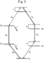
- Figure 2 is an atomic level scheme used in the electromagnetic frequency converter 1.
- the atomic ensemble 4 is prepared in the vapour cell 2 and the heater is energised to vaporise the atoms of the atomic ensemble 4.
- the first and second lasers 6, 8 are energised, with a portion, e.g. half, of the optical or near-infrared radiation from the first laser 6 being separated from the rest of the laser beam and directed through the frequency shifter 12 to shift the frequency of the optical or near-infrared radiation.
- the optical or near-infrared radiation A, R, P from the first and second lasers 6, 8, and the frequency shifter 12 are directed through the input window 10 of the vapour cell 2 so as to be incident upon the atomic ensemble 4.
- the optical or near-infrared radiation P from the second laser 8 (having a Rabi frequency ⁇ P ) excites atomic valence electrons in the atomic ensemble from their ground state
- the frequency of the optical or near-infrared radiation P from the second laser 8 is chosen to be resonant with the atomic transition from the ground state
- the shifted optical or near-infrared radiation R from the first laser 6 (having a Rabi frequency ⁇ R ) excites atomic valence electrons in the atomic ensemble from their intermediate excited state
- the frequency of the shifted optical or near-infrared radiation R from the first laser 6 is chosen to be resonant with the atomic transition from the intermediate excited state
- the optical or near-infrared radiation A from the first laser 6 (having a Rabi frequency ⁇ A ) excites atomic valence electrons in the atomic ensemble from another excited state
- the frequency of the optical or near-infrared radiation A from the first laser 6 is chosen to be detuned from the atomic transition from the excited state
- the microwave or terahertz radiation generator 14 is also energised to produce microwave or terahertz radiation C that is directed along the waveguide 18 and through the input window 16 of the vapour cell 2 so as also to be incident upon the atomic ensemble 4.
- This microwave or terahertz radiation C (having a Rabi frequency ⁇ C ) excites atomic valence electrons from the third Rydberg state
- the frequency of the microwave or terahertz radiation C is chosen to be detuned from the atomic transition from the third Rydberg state
- the input electromagnetic radiation can then be input to the atomic ensemble 4 for conversion.
- the resonant optical or near-infrared radiation R, P (having Rabi frequencies ⁇ R and ⁇ P respectively) from the first and second lasers 6, 8 respectively create a coherence on the
- the microwave or terahertz radiation M (having a Rabi frequency ⁇ M ) is input from the microwave or terahertz input 22 and directed along the waveguide 18 and through the input window 16 of the vapour cell 2 so as to be incident upon the atomic ensemble 4.
- the microwave or terahertz radiation M couples to the electric dipole transition between the Rydberg states
- the microwave or terahertz radiation M When the microwave or terahertz radiation M is input, this creates a coherence on the optical or near-infrared frequency transition
- the electromagnetic frequency converter 1 is being used to convert optical or near-infrared radiation into microwave or terahertz radiation
- the optical or near-infrared radiation L (having a Rabi frequency ⁇ L ) is input from the optical or near-infrared input 20 and directed through the input window 10 (that is transparent to radiation of such frequency) of the vapour cell 2 so as to be incident upon the atomic ensemble 4.
- the optical or near-infrared radiation L couples to the electric dipole transition between the ground and excited states
- the optical or near-infrared radiation L When the optical or near-infrared radiation L is input, this creates a coherence on the microwave or terahertz frequency transition
- the sources of optical or near-infrared radiation P, R have frequencies that are resonant with the respective atomic transitions, the input optical or near-infrared radiation L, or the input microwave or terahertz radiation M, as well as the source of optical or near-infrared radiation A and the source of optical or near-infrared radiation C are detuned from their respective atomic transitions.
- 6>, ⁇ 4 - ⁇ 5 is the detuning of the frequency of the microwave or terahertz radiation C from the atomic transition from the third Rydberg state
- detuning conditions enable a quantum interference effect where the atomic ensemble is nearly transparent for the input electromagnetic radiation while generating a coherence on the transition that produces the output electromagnetic radiation. If these conditions are strongly violated, the input electromagnetic radiation experiences dispersion or absorption in the atomic ensemble and may not be converted into the output field.
- the tolerance in the detunings in order to maximise the efficiency of the conversion is similar to the allowed bandwidth of the input electromagnetic radiation.
- Figure 3 shows an specific example of an atomic level scheme used in an electromagnetic frequency converter according to an embodiment of the present invention, when the vapour cell contains an atomic ensemble of rubidium atoms.
- the atomic ensemble 4 of rubidium atoms is prepared in the vapour cell 2 and the heater is energised to vaporise the rubidium atoms of the atomic ensemble 4.
- the first laser 6, having a frequency of approximately 625 THz, is energised and a portion of its output radiation (having an intensity of approximately 531 mW/mm 2 ) is separated from the rest of the laser beam and directed through the frequency shifter 12 to shift its frequency to approximately 632 THz.
- the remaining 625 THz radiation A (having an intensity of approximately 455 mW/mm 2 ) and the 632 THz radiation R from the first laser 6 are directed through the input window 10 of the vapour cell 2 so as to be incident upon the rubidium atomic ensemble 4.
- the electromagnetic radiation P from the second laser 8 having a frequency of approximately 377 THz and an intensity of approximately 2.3 ⁇ W/mm 2 , is also directed through the input window 10 of the vapour cell 2 so as to be incident upon the rubidium atomic ensemble 4.
- the 377 THz radiation P from the second laser 8 excites atomic valence electrons in the atomic ensemble from their 5S 1/2 ground state into an intermediate 5P 1/2 excited state via an electric dipole transition.
- the 377 THz radiation P is resonant with the atomic transition from the 5S 1/2 ground state to the intermediate 5P 1/2 excited state.
- the shifted 632 THz radiation R from the first laser 6 excites atomic valence electrons in the atomic ensemble from their intermediate 5P 1/2 excited state into a highly excited 30S 1/2 first Rydberg state via an electric dipole transition.
- the microwave radiation generator 14 is also energised to produce microwave radiation C, having a frequency of approximately 157 GHz and an intensity of 239 nW/mm 2 , that is directed along the waveguide 18 and through the input window 16 of the vapour cell 2 so as also to be incident upon the atomic ensemble 4.
- the input electromagnetic radiation can then be input to the atomic ensemble 4 for conversion.
- the microwave radiation M (having a frequency of approximately 157 GHz) is input from the microwave input 22 and directed along the waveguide 18 and through the input window 16 of the vapour cell 2 so as to be incident upon the atomic ensemble 4.
- the input 157 GHz microwave radiation M is converted into near-infrared radiation (having a frequency of approximately 384 THz, which is detuned from the transition between the 5P 3/2 excited state and the 5S 1/2 ground state by 12 MHz).
- This 384 THz near-infrared radiation is then output from the atomic ensemble 4 through the output window 32 in the vapour cell 2 that is transparent to the 384 THz near-infrared radiation, where it is received by the near-infrared radiation output 26.
- the 384 THz near-infrared radiation L (is input from the optical input 20 and directed through the input window 10 (that is transparent to radiation of such frequency) of the vapour cell 2 so as to be incident upon the atomic ensemble 4.
- the 384 THz radiation L couples to the electric dipole transition between the 5P 3/2 excited state and the 5S 1/2 ground state, with the frequency of the 384 THz input radiation L being detuned from the transition by 12 MHz.
- This 157 GHz microwave radiation is then output from the atomic ensemble 4 through the output window 28 in the vapour cell 2 that is transparent to the frequency of the 157 GHz microwave radiation, where it is received by the microwave radiation output 24 via the output waveguide 30.
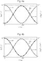
- Figures 4 and 4b show simulation plots of the intensities of input electromagnetic radiation frequencies into the embodiment of the electromagnetic frequency converter operated according to the atomic level scheme shown in Figure 3 .
- the efficiency of the electromagnetic wavelength converter according to the scheme shown in Figure 3 will now be described with reference to the plots shown in Figures 4a and 4b .
- the dots in the plots indicate the results from a numerical integration of the Maxwell-Bloch equations.
- l abs is the absorption length.
- Figure 5 shows another specific example of an atomic level scheme used in an electromagnetic frequency converter according to an embodiment of the present invention, when the vapour cell contains an atomic ensemble of rubidium atoms, but using different transitions to the scheme shown in Figure 3 .
- the input waveguide 18 is positioned to input the microwave or terahertz radiation M from the microwave or terahertz input 22 through the same input window 10 as the optical or near-infrared radiation L.
- the output waveguide 30 is positioned to receive the output microwave or terahertz radiation from the same output window 32 as the output optical or near-infrared radiation L.
- the input window 10 and the output window 32 are transparent to the frequencies of the microwave or terahertz radiation and to the frequencies of the optical or near-infrared radiation that are used.
- the embodiment shown in Figure 4 is able to operate in two main modes of operation: to convert terahertz radiation into near-infrared radiation and vice versa. Both modes of operation will now be described with reference to Figures 1 and 4 .
- the atomic ensemble 4 of rubidium atoms is prepared in the vapour cell 2 and the heater is energised to vaporise the rubidium atoms of the atomic ensemble 4.
- the first laser 6, having a frequency of approximately 617 THz, is energised and a portion of its output radiation (having an intensity of approximately 2.27 W/mm 2 ) is separated from the rest of the laser beam and directed through the frequency shifter 12 to shift its frequency to approximately 625 THz.
- the remaining 617 THz radiation A (having an intensity of approximately 2.27 W/mm 2 ) and the 625 THz radiation R from the first laser 6 are directed through the input window 10 of the vapour cell 2 so as to be incident upon the rubidium atomic ensemble 4.
- the electromagnetic radiation P from the second laser 8 having a frequency of approximately 377 THz and an intensity of approximately 5.95 ⁇ W/mm 2 , is also directed through the input window 10 of the vapour cell 2 so as to be incident upon the rubidium atomic ensemble 4.
- the 377 THz radiation P from the second laser 8 excites atomic valence electrons in the atomic ensemble from their 5S 1/2 ground state into an intermediate 5P 1/2 excited state via an electric dipole transition.
- the 377 THz radiation P is resonant with the atomic transition from the 5S 1/2 ground state to the intermediate 5P 1/2 excited state.
- the shifted 625 THz radiation R from the first laser 6 excites atomic valence electrons in the atomic ensemble from their intermediate 5P 1/2 excited state into a highly excited 23S 1/2 first Rydberg state via an electric dipole transition.
- the terahertz radiation generator 14 is also energised to produce terahertz radiation C, having a frequency of approximately 2.03 THz and an intensity of 12 ⁇ W/mm 2 , that is directed along the waveguide 18 and through the input window 10 of the vapour cell 2 so as also to be incident upon the atomic ensemble 4.
- the input electromagnetic radiation can then be input to the atomic ensemble 4 for conversion.
- the terahertz radiation M (having a frequency of approximately 1.12 THz) is input from the terahertz input 22 and directed along the waveguide 18 and through the input window 10 of the vapour cell 2 so as to be incident upon the atomic ensemble 4.
- This 384 THz near-infrared radiation is then output from the atomic ensemble 4 through the output window 32 in the vapour cell 2 that is transparent to the 384 THz near-infrared radiation, where it is received by the near-infrared radiation output 26.
- the electromagnetic frequency converter 1 is being used to convert near-infrared radiation into terahertz radiation
- the 384 THz near-infrared radiation L is input from the optical input 20 and directed through the input window 10 (that is transparent to radiation of such frequency) of the vapour cell 2 so as to be incident upon the atomic ensemble 4.
- the 384 THz radiation L couples to the electric dipole transition between the 5P 3/2 excited state and the S 1/2 ground state, with the frequency of the 384 THz input radiation L being detuned from the transition by 12.1 MHz.
- This 1.12 THz terahertz radiation is then output from the atomic ensemble 4 through the output window 32 in the vapour cell 2 that is transparent to the frequency of the 1.12 THz terahertz radiation, where it is received by the terahertz radiation output 24 via the output waveguide 30.
- Figures 6 and 6b show simulation plots of the intensities of input electromagnetic radiation frequencies into the embodiment of the electromagnetic frequency converter operated according to the atomic level scheme shown in Figure 5 .
- the efficiency of the electromagnetic wavelength converter according to the scheme shown in Figure 5 will now be described with reference to the plots shown in Figures 6a and 6b .
- the dots in the plots indicate the results from a numerical integration of the Maxwell-Bloch equations.
- an electromagnetic frequency converter offers an efficient frequency conversion mechanism between optical or near-infrared radiation and microwave or terahertz frequency radiation (or vice versa).
- Such a converter does not require the use of a cavity, thus offering a greater bandwidth for conversion frequencies.
- the converter does not require any optical pumping because the highly excited Rydberg states are unpopulated at room temperature so there is no thermal noise to suppress, and does not require any micro-fabrication of components because the active component of the converter is simply a volume of atoms to which radiation is applied.
- the embodiments shown in the Figures use four drive fields, i.e. three optical or near-infrared fields and one microwave field, to perform the conversion
- 3> may be performed using only a single drive field or using three or more drive fields via two or more intermediate states through respective transitions.
- 4> may be performed using only a single drive field or using three or more drive fields via two or more intermediate states through respective transitions.
Landscapes
- Physics & Mathematics (AREA)
- Nonlinear Science (AREA)
- General Physics & Mathematics (AREA)
- Optics & Photonics (AREA)
- Optical Modulation, Optical Deflection, Nonlinear Optics, Optical Demodulation, Optical Logic Elements (AREA)
Claims (15)
- Elektromagnetischer Frequenzumrichter (1) zum Umrichten elektromagnetischer Eingangsstrahlung, um elektromagnetische Strahlung einer anderen Frequenz auszugeben, wobei der elektromagnetische Frequenzumrichter umfasst:ein atomares Ensemble (4);eine oder mehrere erste Quellen (6, 8) von elektromagnetischer Strahlung (P, R), die jeweils eine Frequenz aufweist, die aus einem Satz möglicher atomarer Übergangsfrequenzen für die atomaren Valenzelektronen im atomaren Ensemble ausgewählt ist, wobei die Summe der Frequenzen der einen oder mehreren ersten Quellen zwischen 600 THz und 1500 THz liegt, wobei die elektromagnetische Strahlung von der einen oder den mehreren ersten Quellen angeordnet ist, auf das atomare Ensemble zu fallen, um atomare Valenzelektronen im atomaren Ensemble von einem Grundzustand zu einem ersten Rydberg-Zustand anzuregen;eine oder mehrere zweite Quellen (6, 14) elektromagnetischer Strahlung (A, C), die jeweils eine Frequenz aufweisen, die aus einem Satz möglicher atomarer Übergangsfrequenzen für die atomaren Valenzelektronen im atomaren Ensemble ausgewählt ist, wobei die Summe der Frequenzen der einen oder mehreren zweiten Quellen zwischen 300 THz und 750 THz liegt, wobei die elektromagnetische Strahlung von der einen oder den mehreren zweiten Quellen angeordnet ist, auf das atomare Ensemble zu fallen, um atomare Valenzelektronen im atomaren Ensemble von einem angeregten Zustand zu einem zweiten Rydberg-Zustand anzuregen, wobei der angeregte Zustand mit dem Grundzustand durch einen atomaren Übergang aufweisend eine Frequenz zwischen 193 THz und 800 THz für die atomaren Valenzelektronen im atomaren Ensemble verbunden ist und der zweite Rydberg-Zustand mit dem ersten Rydberg-Zustand durch einen atomaren Übergang aufweisend eine Frequenz zwischen 300 MHz und 3 THz für die atomaren Valenzelektronen im atomaren Ensemble verbunden ist;einen ersten Eingang (20) und/oder Ausgang (26) für elektromagnetische Strahlung (L) aufweisend eine Frequenz zwischen 193 THz und 800 THz, wobei der erste Eingang oder Ausgang angeordnet ist, an das atomare Ensemble so gekoppelt zu sein, dass die elektromagnetische Strahlung vom ersten Eingang auf das atomare Ensemble fällt oder vom atomaren Ensemble beim ersten Ausgang empfangen wird; undeinen zweiten Eingang (22) und/oder Ausgang (24) für elektromagnetische Strahlung (M) aufweisend eine Frequenz zwischen Frequenz zwischen 300 MHz und 3 THz, wobei der zweite Eingang oder Ausgang angeordnet ist, an das atomare Ensemble so gekoppelt zu sein, dass die elektromagnetische Strahlung vom zweiten Eingang auf das atomare Ensemble fällt oder vom atomaren Ensemble beim zweiten Ausgang empfangen wird;wobei der elektromagnetische Frequenzumrichter so angeordnet ist, dass bei Anwendung der einen oder mehreren ersten und einen oder mehreren zweiten Quellen elektromagnetischer Strahlung, die auf das atomare Ensemble fallen soll, Eingang von elektromagnetischer Strahlung aus dem ersten Eingang, die eine Frequenz zwischen 193 THz und 800 THz aufweist und die an den atomaren Übergang zwischen dem Grundzustand und dem angeregten Zustand koppelt, oder Eingang von elektromagnetischer Strahlung aus dem zweiten Eingang, die eine Frequenz zwischen 300 MHz und 3 THz aufweist und die an den atomaren Übergang zwischen dem ersten Rydberg-Zustand und dem zweiten Rydberg-Zustand koppelt, bewirkt, dass elektromagnetische Strahlung aufweisend eine Frequenz zwischen 300 MHz und 3 THz von dem atomaren Übergang zwischen dem zweiten Rydberg-Zustand und dem ersten Rydberg-Zustand aus dem zweiten Ausgang ausgegeben wird bzw. elektromagnetische Strahlung aufweisend eine Frequenz zwischen 193 THz und 800 THz von dem atomaren Übergang zwischen dem angeregten Zustand und dem Grundzustand aus dem ersten Ausgang ausgegeben wird.
- Elektromagnetischer Frequenzumrichter (1) nach Anspruch 1, wobei die eine oder mehreren ersten Quellen (6, 8) elektromagnetischer Strahlung (P, R) umfassen:eine oder mehrere erste Quellen elektromagnetischer Strahlung, die jeweils eine Frequenz aufweisen, die aus einem Satz möglicher atomarer Übergangsfrequenzen für die atomaren Valenzelektronen im atomaren Ensemble (4) ausgewählt ist, wobei die Summe der Frequenzen der einen oder mehreren ersten Quellen zwischen 193 THz und 800 THz liegt, wobei die elektromagnetische Strahlung von der einen oder den mehreren ersten Quellen angeordnet ist, auf das atomare Ensemble zu fallen, um atomare Valenzelektronen im atomaren Ensemble von einem Grundzustand zu einem angeregten Zwischenzustand anzuregen; undeine oder mehrere dritte Quellen elektromagnetischer Strahlung, die jeweils eine Frequenz aufweisen, die aus einem Satz möglicher atomarer Übergangsfrequenzen für die atomaren Valenzelektronen im atomaren Ensemble ausgewählt ist, wobei die Summe der Frequenzen der einen oder mehreren dritten Quellen zwischen 193 THz und 800 THz liegt, wobei die elektromagnetische Strahlung von der einen oder den mehreren dritten Quellen angeordnet ist, auf das atomare Ensemble zu fallen, um atomare Valenzelektronen im atomaren Ensemble vom angeregten Zwischenzustand zum ersten Rydberg-Zustand anzuregen.
- Elektromagnetischer Frequenzumrichter (1) nach Anspruch 1 oder 2, wobei die eine oder mehreren zweiten Quellen (6, 14) elektromagnetischer Strahlung (A, C) umfassen:eine oder mehrere zweite Quellen elektromagnetischer Strahlung, die jeweils eine Frequenz aufweisen, die aus einem Satz möglicher atomarer Übergangsfrequenzen für die atomaren Valenzelektronen im atomaren Ensemble (4) ausgewählt ist, wobei die Summe der Frequenzen der einen oder mehreren zweiten Quellen zwischen 300 THz und 750 THz liegt, wobei die elektromagnetische Strahlung von der einen oder den mehreren zweiten Quellen angeordnet ist, auf das atomare Ensemble zu fallen, um atomare Valenzelektronen im atomaren Ensemble von einem angeregten Zustand zu einem dritten Rydberg-Zustand anzuregen; undeine oder mehrere vierte Quellen elektromagnetischer Strahlung, die jeweils eine Frequenz aufweisen, die aus einem Satz möglicher atomarer Übergangsfrequenzen für die atomaren Valenzelektronen im atomaren Ensemble ausgewählt ist, wobei die Summe der Frequenzen der einen oder mehreren vierten Quellen zwischen 300 MHz und 3 THz liegt, wobei die elektromagnetische Strahlung von der einen oder den mehreren vierten Quellen angeordnet ist, auf das atomare Ensemble zu fallen, um atomare Valenzelektronen im atomaren Ensemble vom dritten Rydberg-Zustand zum zweiten Rydberg-Zustand anzuregen.
- Elektromagnetischer Frequenzumrichter (1) nach einem der vorstehenden Ansprüche, weiter umfassend eine Dampfzelle (2) innerhalb der das atomare Ensemble (4) gehalten wird, wobei die Dampfzelle ein Eingangsfenster (10, 16) umfasst, das für die elektromagnetische Strahlung von einer oder mehreren von: der einen oder den mehreren ersten Quellen (6, 8) elektromagnetischer Strahlung (P, R), der einen oder den mehreren zweiten Quellen (6, 14) elektromagnetischer Strahlung (A, C), dem ersten Eingang (20) für elektromagnetische Strahlung (L) und dem zweiten Eingang (22) für elektromagnetische Strahlung (M) transparent ist, die angeordnet sind, die entsprechende elektromagnetische Strahlung daraus so durch das Eingangsfenster zu lenken, dass sie auf das atomare Ensemble (4) fällt.
- Elektromagnetischer Frequenzumrichter (1) nach Anspruch 4, wobei die Dampfzelle (2) ein Ausgangsfenster (28, 32) umfasst, das für die elektromagnetische Strahlung von einem oder beiden des ersten Ausgangs (26) für elektromagnetische Strahlung (L) und des zweiten Ausgangs (24) für elektromagnetische Strahlung (M) transparent ist, die angeordnet sind, die elektromagnetische Strahlung von dem atomaren Ensemble (4) durch das Ausgangsfenster zu empfangen.
- Elektromagnetischer Frequenzumrichter (1) nach Anspruch 4 oder 5, wobei der elektromagnetische Frequenzumrichter eine Heizeinrichtung in guter thermischer Kommunikation mit der Dampfzelle (2) umfasst und angeordnet ist, das atomare Ensemble (4) zu erwärmen.
- Elektromagnetischer Frequenzumrichter (1) nach Anspruch 3, wobei die eine oder mehreren vierten Quellen einen Mikrowellen- oder Terahertzstrahlungsgenerator und einen Wellenleiter (18), der angeordnet ist, die Mikrowelle oder Terahertzstrahlung, die durch den Mikrowellen- oder Terahertzstrahlungsgenerator erzeugt wird, an das atomare Ensemble (4) zu koppeln, umfasst, sodass die Mikrowelle oder Terahertzstrahlung auf das atomare Ensemble fällt.
- Elektromagnetischer Frequenzumrichter (1) nach einem der vorstehenden Ansprüche, wobei der zweite Ausgang (24) einen Wellenleiter (20) umfasst, der angeordnet ist, die elektromagnetische Strahlung aufweisend eine Frequenz zwischen 0,1 mm und 1 m zu sammeln, die aus dem atomaren Ensemble (4) ausgegeben wird.
- Elektromagnetischer Frequenzumrichter (1) nach Anspruch 2, wobei der angeregte Zwischenzustand der Valenzelektronen im atomaren Ensemble (4), der durch Anregung der einen oder mehreren ersten Quellen erreicht wird, und der angeregte Zustand der Valenzelektronen im atomaren Ensemble, der durch Anregung durch den ersten Eingang (20) erreicht wird, dieselbe Hauptquantenzahl aufweisen, aber einen unterschiedlichen Hyperfeinzustand umfassen.
- Elektromagnetischer Frequenzumrichter (1) nach einem der vorstehenden Ansprüche, wobei der erste und zweite Rydberg-Zustand eine Hauptquantenzahl zwischen 20 und 80, z.B. zwischen 30 und 70, z.B. zwischen 40 und 60 aufweisen.
- Elektromagnetischer Frequenzumrichter (1) nach einem der vorstehenden Ansprüche, wobei der erste Rydberg-Zustand und der zweite Rydberg-Zustand dieselbe Hauptquantenzahl aufweisen, aber eine oder mehrere einer unterschiedlichen azimutalen Quantenzahl und einer unterschiedlichen Bahndrehimpulsquantenzahl umfassen.
- Elektromagnetischer Frequenzumrichter (1) nach Anspruch 2 und 3, wobei, wenn der elektromagnetische Frequenzumrichter eine erste Quelle, eine zweite Quelle, eine dritte Quelle und eine vierte Quelle umfasst, die Frequenzen und Intensitäten der elektromagnetischen Strahlung von der ersten, zweiten, dritten und vierten Quelle die folgenden Bedingungen erfüllen:


- Elektromagnetischer Frequenzumrichter (1) nach einem der vorstehenden Ansprüche, wobei, wenn die elektromagnetische Eingangsstrahlung vom zweiten Eingang (22) eingegeben wird, die Differenz in der Frequenz der zweiten elektromagnetischen Eingangsstrahlung und der Frequenz des atomaren Übergangs zwischen dem ersten und zweiten Rydberg-Zustand der Valenzelektronen des atomaren Ensembles (4) viel kleiner ist als die Frequenz des Übergangs zwischen dem ersten und zweiten Rydberg-Zustand selbst.
- Elektromagnetischer Frequenzumrichter (1) nach einem der vorstehenden Ansprüche, wobei, wenn die elektromagnetische Strahlung vom ersten Eingang (20) eingegeben wird, die Differenz in der Frequenz der ersten elektromagnetischen Eingangsstrahlung und der Frequenz des atomaren Übergangs zwischen dem Grund- und angeregten Zustand der Valenzelektronen des atomaren Ensembles (4) viel kleiner ist als die Frequenz des Übergangs zwischen dem Grund- und angeregten Zustand selbst.
- Verfahren zum Umwandeln elektromagnetischer Eingangsstrahlung (20, 22), um elektromagnetische Strahlung (24, 26) einer anderen Frequenz auszugeben, das Verfahren umfassend:Anregen atomarer Valenzelektronen in einem atomaren Ensemble (4) von einem Grundzustand zu einem ersten Rydberg-Zustand durch Anordnen elektromagnetischer Strahlung von einer oder mehreren ersten Quellen (6, 8) elektromagnetischer Strahlung (P, R), die auf das atomare Ensemble fallen soll, wobei die Frequenz jeder der einen oder mehreren ersten Quellen elektromagnetischer Strahlung aus einem Satz möglicher atomarer Übergangsfrequenzen für die atomaren Valenzelektronen im atomaren Ensemble ausgewählt ist und die Summe der Frequenzen der einen oder mehreren ersten Quellen zwischen 600 THz und 1500 THz liegt;Anregen atomarer Valenzelektronen in einem atomaren Ensemble von einem angeregten Zustand zu einem zweiten Rydberg-Zustand durch Anordnen elektromagnetischer Strahlung von einer oder mehreren zweiten Quellen (6, 14) elektromagnetischer Strahlung (A, C), die auf das atomare Ensemble fallen soll, wobei der angeregte Zustand mit dem Grundzustand durch einen atomaren Übergang verbunden ist, der eine Frequenz zwischen 193 THz und 800 THz für die atomaren Valenzelektronen im atomaren Ensemble aufweist, und der zweite Rydberg-Zustand mit dem ersten Rydberg-Zustand durch einen atomaren Übergang aufweisend eine Frequenz zwischen 300 MHz und 3 THz für die atomaren Valenzelektronen im atomaren Ensemble verbunden ist, und wobei die Frequenz jeder der einen oder mehreren zweiten Quellen elektromagnetischer Strahlung aus einem Satz möglicher atomarer Übergangsfrequenzen für die atomaren Valenzelektronen im atomaren Ensemble ausgewählt ist und die Summe der Frequenzen der einen oder mehreren zweiten Quellen zwischen 300 THz und 750 THz liegt;Eingeben elektromagnetischer Strahlung, die eine Frequenz zwischen 193 THz und 800 THz oder zwischen 300 MHz und 3 THz aufweist, in das atomare Ensemble, sodass die elektromagnetische Strahlung auf das atomare Ensemble fällt;wobei das atomare Ensemble so angeordnet ist, dass bei Anwendung der einen oder mehreren ersten und einen oder mehreren zweiten Quellen elektromagnetischer Strahlung, die auf das atomare Ensemble fallen sollen, Eingang von elektromagnetischer Strahlung aus dem ersten Eingang (20), die eine Frequenz zwischen 193 THz und 800 THz aufweist und die an den atomaren Übergang zwischen dem Grundzustand und dem angeregten Zustand koppelt, oder Eingang von elektromagnetischer Strahlung aus dem zweiten Eingang (22), die eine Frequenz zwischen 300 MHz und 3 THz aufweist und die an den Übergang zwischen dem ersten Rydberg-Zustand und dem zweiten Rydberg-Zustand koppelt, bewirkt, dass elektromagnetische Strahlung aufweisend eine Frequenz zwischen 300 MHz und 3 THz von dem atomaren Übergang zwischen dem zweiten Rydberg-Zustand und dem ersten Rydberg-Zustand bzw. elektromagnetische Strahlung aufweisend eine Frequenz zwischen 193 THz und 800 THz von dem atomaren Übergang zwischen dem angeregten Zustand und dem Grundzustand aus dem atomaren Ensemble ausgegeben wird.
Applications Claiming Priority (2)
| Application Number | Priority Date | Filing Date | Title |
|---|---|---|---|
| GBGB1522640.0A GB201522640D0 (en) | 2015-12-22 | 2015-12-22 | Electromagnetic frequency converter |
| PCT/GB2016/054000 WO2017109475A1 (en) | 2015-12-22 | 2016-12-20 | Electromagnetic frequency converter |
Publications (2)
| Publication Number | Publication Date |
|---|---|
| EP3394670A1 EP3394670A1 (de) | 2018-10-31 |
| EP3394670B1 true EP3394670B1 (de) | 2020-02-05 |
Family
ID=55311431
Family Applications (1)
| Application Number | Title | Priority Date | Filing Date |
|---|---|---|---|
| EP16823030.8A Active EP3394670B1 (de) | 2015-12-22 | 2016-12-20 | Elektromagnetischer frequenzumrichter |
Country Status (5)
| Country | Link |
|---|---|
| US (1) | US10216062B2 (de) |
| EP (1) | EP3394670B1 (de) |
| CN (1) | CN108604038B (de) |
| GB (1) | GB201522640D0 (de) |
| WO (1) | WO2017109475A1 (de) |
Cited By (3)
| Publication number | Priority date | Publication date | Assignee | Title |
|---|---|---|---|---|
| US11921142B2 (en) | 2021-11-19 | 2024-03-05 | Rohde & Schwarz Gmbh & Co. Kg | Measurement system and method for analyzing RF signals |
| EP4502626A1 (de) * | 2023-07-31 | 2025-02-05 | Rohde & Schwarz GmbH & Co. KG | Sensorsystem und verfahren zur analyse eines spektrums eines elektromagnetischen signals |
| US12332290B2 (en) | 2021-10-26 | 2025-06-17 | Rohde & Schwarz Gmbh & Co. Kg | Measurement system for analysing radio frequency signals, and method of operating the same |
Families Citing this family (16)
| Publication number | Priority date | Publication date | Assignee | Title |
|---|---|---|---|---|
| CN106159641B (zh) * | 2016-09-05 | 2017-07-18 | 华讯方舟科技有限公司 | 携带轨道角动量的太赫兹波的发生装置及产生方法 |
| CN107917892B (zh) * | 2017-11-15 | 2020-11-10 | 山西大学 | 太赫兹波的高分辨成像装置 |
| EP4542237A3 (de) | 2017-12-18 | 2025-06-25 | Rydberg Technologies Inc. | Messelement für atombasiertes elektromagnetisches feld und messsystem |
| US10852620B2 (en) | 2018-05-07 | 2020-12-01 | National University Of Singapore | Continuous-wave terahertz generation via optically pumped rydberg states |
| US11415614B2 (en) * | 2019-01-23 | 2022-08-16 | ColdQuanta, Inc. | Rydberg-particle-based 3D microwave sensor |
| US11002777B2 (en) * | 2019-01-23 | 2021-05-11 | ColdQuanta, Inc. | Microwave sensor using rydberg particles |
| US10979147B2 (en) * | 2019-03-11 | 2021-04-13 | Government Of The United States Of America, As Represented By The Secretary Of Commerce | Rydberg atom mixer and determining phase of modulated carrier radiation |
| US11204513B2 (en) * | 2019-05-03 | 2021-12-21 | Yissum Research Development Company Of The Hebrew University Of Jerusamem Ltd | Integrated frequency referencing system |
| WO2021003580A1 (en) * | 2019-07-11 | 2021-01-14 | National Research Council Of Canada | Rydberg exciton quantum simulator |
| CN112448258B (zh) * | 2019-08-29 | 2022-06-24 | 中国科学院上海微系统与信息技术研究所 | 激光器 |
| US11988759B2 (en) | 2020-07-06 | 2024-05-21 | ColdQuanta, Inc. | Rydberg-molecule-based microwave direction finding |
| CN112701554B (zh) * | 2020-12-25 | 2021-12-10 | 中国航天科工集团第二研究院 | 基于里德堡原子激发四波混频的太赫兹波产生方法及系统 |
| US11777614B2 (en) * | 2021-02-16 | 2023-10-03 | Hughes Network Systems, Llc | Quantum communication transceiver based on quantum entangled atomic states |
| GB2605651A (en) | 2021-04-09 | 2022-10-12 | British Telecomm | Electromagnetic field receiver |
| GB2605650B (en) | 2021-04-09 | 2023-06-07 | British Telecomm | Electromagnetic field detector |
| CN119335495B (zh) * | 2024-10-16 | 2025-05-27 | 中国人民解放军军事科学院系统工程研究院 | 一种基于里德堡原子接收机的外辐射源雷达 |
Family Cites Families (7)
| Publication number | Priority date | Publication date | Assignee | Title |
|---|---|---|---|---|
| US3720882A (en) | 1970-08-03 | 1973-03-13 | Research Corp | Parametric frequency conversion |
| US5771117A (en) * | 1996-06-17 | 1998-06-23 | The Board Of Trustees Of The Leland Stanford Junior University | Method and apparatus for nonlinear frequency generation using a strongly-driven local oscillator |
| AU2001271363A1 (en) * | 2000-06-20 | 2002-01-02 | Actinix | Generating coherent vacuum ultraviolet radiation using four wave mixing |
| US7672342B2 (en) * | 2005-05-24 | 2010-03-02 | MAX-PLANCK-Gesellschaft zur Förderung der Wissenschaften e.V. | Method and radiation source for generating pulsed coherent radiation |
| US20090074016A1 (en) * | 2006-10-18 | 2009-03-19 | Orval Mamer | Apparatus for Terahertz wave generation from water vapor |
| CN202916565U (zh) * | 2012-09-28 | 2013-05-01 | 华东师范大学 | 一种原子移频器 |
| CN104714110B (zh) * | 2015-04-02 | 2017-09-26 | 山西大学 | 基于电磁诱导透明效应测量高频微波场强的装置和方法 |
-
2015
- 2015-12-22 GB GBGB1522640.0A patent/GB201522640D0/en not_active Ceased
-
2016
- 2016-12-20 US US16/063,845 patent/US10216062B2/en active Active
- 2016-12-20 CN CN201680075533.3A patent/CN108604038B/zh active Active
- 2016-12-20 EP EP16823030.8A patent/EP3394670B1/de active Active
- 2016-12-20 WO PCT/GB2016/054000 patent/WO2017109475A1/en not_active Ceased
Non-Patent Citations (1)
| Title |
|---|
| None * |
Cited By (3)
| Publication number | Priority date | Publication date | Assignee | Title |
|---|---|---|---|---|
| US12332290B2 (en) | 2021-10-26 | 2025-06-17 | Rohde & Schwarz Gmbh & Co. Kg | Measurement system for analysing radio frequency signals, and method of operating the same |
| US11921142B2 (en) | 2021-11-19 | 2024-03-05 | Rohde & Schwarz Gmbh & Co. Kg | Measurement system and method for analyzing RF signals |
| EP4502626A1 (de) * | 2023-07-31 | 2025-02-05 | Rohde & Schwarz GmbH & Co. KG | Sensorsystem und verfahren zur analyse eines spektrums eines elektromagnetischen signals |
Also Published As
| Publication number | Publication date |
|---|---|
| CN108604038A (zh) | 2018-09-28 |
| US20180373118A1 (en) | 2018-12-27 |
| EP3394670A1 (de) | 2018-10-31 |
| CN108604038B (zh) | 2022-03-01 |
| US10216062B2 (en) | 2019-02-26 |
| WO2017109475A1 (en) | 2017-06-29 |
| GB201522640D0 (en) | 2016-02-03 |
Similar Documents
| Publication | Publication Date | Title |
|---|---|---|
| EP3394670B1 (de) | Elektromagnetischer frequenzumrichter | |
| Band | Light and matter: electromagnetism, optics, spectroscopy and lasers | |
| US10600482B2 (en) | Quantum memory device | |
| Chergui et al. | Progress and prospects in nonlinear extreme-ultraviolet and X-ray optics and spectroscopy | |
| Freund et al. | Free-electron lasers: Vacuum electronic generators of coherent radiation | |
| Harris et al. | Core-excited metastable levels: application to spectroscopy, to the generation of picosecond extreme-ultraviolet pulses, and to lasers | |
| Khan | Free-electron lasers | |
| Neil | Accelerator sources for THz science: A review | |
| Petrillo et al. | Coherent, high repetition rate tender x-ray free-electron laser seeded by an extreme ultra-violet free-electron laser oscillator | |
| ALEGRO collaboration | Towards an advanced linear international collider | |
| JPH01179478A (ja) | 周波数増加レーザ及び光学的増幅器 | |
| Pellegrini et al. | The development of X-ray free-electron lasers | |
| Cashen et al. | Optical forces on atoms in nonmonochromatic light | |
| Carbajo et al. | Structured light at the extreme: Harnessing spatiotemporal control for high-field laser-matter interactions | |
| Lin et al. | Review on the recent progress of laser frontiers in China | |
| Carlsten et al. | New source technologies and their impact on future light sources | |
| Ganeev | Resonance enhancement in laser-produced plasmas: concepts and applications | |
| Liu et al. | Fast and slow plasma waves excitation by counterpropagating lasers in a hot plasma | |
| He et al. | Energy-transfer kinetics driven by midinfrared amplified spontaneous emission after two-photon excitation from Xe (s0) to the Xe (6p [1/2] 0) state | |
| Romaniuk | European X-Ray Free Electron Laser (EXFEL): local implications | |
| Kumar et al. | Broadband femtosecond lasers enable efficient two-photon excitation of the ultranarrow linewidth singlet 1 s 2 s state in helium | |
| Kärtner | Terahertz accelerator based electron and x-ray sources | |
| US7106776B1 (en) | Discharge-pumped “dressed-atom” coherent light amplifier and generators | |
| Bhatia et al. | Laser amplification without population inversion on the D 1 line of the Cs atom with semiconductor diode lasers | |
| Colson | Long range coherence in free electron lasers |
Legal Events
| Date | Code | Title | Description |
|---|---|---|---|
| STAA | Information on the status of an ep patent application or granted ep patent |
Free format text: STATUS: UNKNOWN |
|
| STAA | Information on the status of an ep patent application or granted ep patent |
Free format text: STATUS: THE INTERNATIONAL PUBLICATION HAS BEEN MADE |
|
| PUAI | Public reference made under article 153(3) epc to a published international application that has entered the european phase |
Free format text: ORIGINAL CODE: 0009012 |
|
| STAA | Information on the status of an ep patent application or granted ep patent |
Free format text: STATUS: REQUEST FOR EXAMINATION WAS MADE |
|
| 17P | Request for examination filed |
Effective date: 20180626 |
|
| AK | Designated contracting states |
Kind code of ref document: A1 Designated state(s): AL AT BE BG CH CY CZ DE DK EE ES FI FR GB GR HR HU IE IS IT LI LT LU LV MC MK MT NL NO PL PT RO RS SE SI SK SM TR |
|
| AX | Request for extension of the european patent |
Extension state: BA ME |
|
| DAV | Request for validation of the european patent (deleted) | ||
| DAX | Request for extension of the european patent (deleted) | ||
| GRAP | Despatch of communication of intention to grant a patent |
Free format text: ORIGINAL CODE: EPIDOSNIGR1 |
|
| STAA | Information on the status of an ep patent application or granted ep patent |
Free format text: STATUS: GRANT OF PATENT IS INTENDED |
|
| INTG | Intention to grant announced |
Effective date: 20190723 |
|
| GRAS | Grant fee paid |
Free format text: ORIGINAL CODE: EPIDOSNIGR3 |
|
| GRAA | (expected) grant |
Free format text: ORIGINAL CODE: 0009210 |
|
| STAA | Information on the status of an ep patent application or granted ep patent |
Free format text: STATUS: THE PATENT HAS BEEN GRANTED |
|
| AK | Designated contracting states |
Kind code of ref document: B1 Designated state(s): AL AT BE BG CH CY CZ DE DK EE ES FI FR GB GR HR HU IE IS IT LI LT LU LV MC MK MT NL NO PL PT RO RS SE SI SK SM TR |
|
| REG | Reference to a national code |
Ref country code: GB Ref legal event code: FG4D |
|
| REG | Reference to a national code |
Ref country code: AT Ref legal event code: REF Ref document number: 1230322 Country of ref document: AT Kind code of ref document: T Effective date: 20200215 |
|
| REG | Reference to a national code |
Ref country code: DE Ref legal event code: R096 Ref document number: 602016029238 Country of ref document: DE |
|
| REG | Reference to a national code |
Ref country code: IE Ref legal event code: FG4D |
|
| REG | Reference to a national code |
Ref country code: CH Ref legal event code: EP |
|
| REG | Reference to a national code |
Ref country code: NL Ref legal event code: MP Effective date: 20200205 |
|
| PG25 | Lapsed in a contracting state [announced via postgrant information from national office to epo] |
Ref country code: NO Free format text: LAPSE BECAUSE OF FAILURE TO SUBMIT A TRANSLATION OF THE DESCRIPTION OR TO PAY THE FEE WITHIN THE PRESCRIBED TIME-LIMIT Effective date: 20200505 Ref country code: FI Free format text: LAPSE BECAUSE OF FAILURE TO SUBMIT A TRANSLATION OF THE DESCRIPTION OR TO PAY THE FEE WITHIN THE PRESCRIBED TIME-LIMIT Effective date: 20200205 Ref country code: PT Free format text: LAPSE BECAUSE OF FAILURE TO SUBMIT A TRANSLATION OF THE DESCRIPTION OR TO PAY THE FEE WITHIN THE PRESCRIBED TIME-LIMIT Effective date: 20200628 Ref country code: RS Free format text: LAPSE BECAUSE OF FAILURE TO SUBMIT A TRANSLATION OF THE DESCRIPTION OR TO PAY THE FEE WITHIN THE PRESCRIBED TIME-LIMIT Effective date: 20200205 |
|
| REG | Reference to a national code |
Ref country code: LT Ref legal event code: MG4D |
|
| PG25 | Lapsed in a contracting state [announced via postgrant information from national office to epo] |
Ref country code: IS Free format text: LAPSE BECAUSE OF FAILURE TO SUBMIT A TRANSLATION OF THE DESCRIPTION OR TO PAY THE FEE WITHIN THE PRESCRIBED TIME-LIMIT Effective date: 20200605 Ref country code: LV Free format text: LAPSE BECAUSE OF FAILURE TO SUBMIT A TRANSLATION OF THE DESCRIPTION OR TO PAY THE FEE WITHIN THE PRESCRIBED TIME-LIMIT Effective date: 20200205 Ref country code: SE Free format text: LAPSE BECAUSE OF FAILURE TO SUBMIT A TRANSLATION OF THE DESCRIPTION OR TO PAY THE FEE WITHIN THE PRESCRIBED TIME-LIMIT Effective date: 20200205 Ref country code: GR Free format text: LAPSE BECAUSE OF FAILURE TO SUBMIT A TRANSLATION OF THE DESCRIPTION OR TO PAY THE FEE WITHIN THE PRESCRIBED TIME-LIMIT Effective date: 20200506 Ref country code: BG Free format text: LAPSE BECAUSE OF FAILURE TO SUBMIT A TRANSLATION OF THE DESCRIPTION OR TO PAY THE FEE WITHIN THE PRESCRIBED TIME-LIMIT Effective date: 20200505 Ref country code: HR Free format text: LAPSE BECAUSE OF FAILURE TO SUBMIT A TRANSLATION OF THE DESCRIPTION OR TO PAY THE FEE WITHIN THE PRESCRIBED TIME-LIMIT Effective date: 20200205 |
|
| PG25 | Lapsed in a contracting state [announced via postgrant information from national office to epo] |
Ref country code: NL Free format text: LAPSE BECAUSE OF FAILURE TO SUBMIT A TRANSLATION OF THE DESCRIPTION OR TO PAY THE FEE WITHIN THE PRESCRIBED TIME-LIMIT Effective date: 20200205 |
|
| PG25 | Lapsed in a contracting state [announced via postgrant information from national office to epo] |
Ref country code: ES Free format text: LAPSE BECAUSE OF FAILURE TO SUBMIT A TRANSLATION OF THE DESCRIPTION OR TO PAY THE FEE WITHIN THE PRESCRIBED TIME-LIMIT Effective date: 20200205 Ref country code: RO Free format text: LAPSE BECAUSE OF FAILURE TO SUBMIT A TRANSLATION OF THE DESCRIPTION OR TO PAY THE FEE WITHIN THE PRESCRIBED TIME-LIMIT Effective date: 20200205 Ref country code: SK Free format text: LAPSE BECAUSE OF FAILURE TO SUBMIT A TRANSLATION OF THE DESCRIPTION OR TO PAY THE FEE WITHIN THE PRESCRIBED TIME-LIMIT Effective date: 20200205 Ref country code: CZ Free format text: LAPSE BECAUSE OF FAILURE TO SUBMIT A TRANSLATION OF THE DESCRIPTION OR TO PAY THE FEE WITHIN THE PRESCRIBED TIME-LIMIT Effective date: 20200205 Ref country code: SM Free format text: LAPSE BECAUSE OF FAILURE TO SUBMIT A TRANSLATION OF THE DESCRIPTION OR TO PAY THE FEE WITHIN THE PRESCRIBED TIME-LIMIT Effective date: 20200205 Ref country code: EE Free format text: LAPSE BECAUSE OF FAILURE TO SUBMIT A TRANSLATION OF THE DESCRIPTION OR TO PAY THE FEE WITHIN THE PRESCRIBED TIME-LIMIT Effective date: 20200205 Ref country code: LT Free format text: LAPSE BECAUSE OF FAILURE TO SUBMIT A TRANSLATION OF THE DESCRIPTION OR TO PAY THE FEE WITHIN THE PRESCRIBED TIME-LIMIT Effective date: 20200205 Ref country code: DK Free format text: LAPSE BECAUSE OF FAILURE TO SUBMIT A TRANSLATION OF THE DESCRIPTION OR TO PAY THE FEE WITHIN THE PRESCRIBED TIME-LIMIT Effective date: 20200205 |
|
| REG | Reference to a national code |
Ref country code: DE Ref legal event code: R097 Ref document number: 602016029238 Country of ref document: DE |
|
| REG | Reference to a national code |
Ref country code: AT Ref legal event code: MK05 Ref document number: 1230322 Country of ref document: AT Kind code of ref document: T Effective date: 20200205 |
|
| PLBE | No opposition filed within time limit |
Free format text: ORIGINAL CODE: 0009261 |
|
| STAA | Information on the status of an ep patent application or granted ep patent |
Free format text: STATUS: NO OPPOSITION FILED WITHIN TIME LIMIT |
|
| 26N | No opposition filed |
Effective date: 20201106 |
|
| PG25 | Lapsed in a contracting state [announced via postgrant information from national office to epo] |
Ref country code: AT Free format text: LAPSE BECAUSE OF FAILURE TO SUBMIT A TRANSLATION OF THE DESCRIPTION OR TO PAY THE FEE WITHIN THE PRESCRIBED TIME-LIMIT Effective date: 20200205 Ref country code: IT Free format text: LAPSE BECAUSE OF FAILURE TO SUBMIT A TRANSLATION OF THE DESCRIPTION OR TO PAY THE FEE WITHIN THE PRESCRIBED TIME-LIMIT Effective date: 20200205 |
|
| PG25 | Lapsed in a contracting state [announced via postgrant information from national office to epo] |
Ref country code: PL Free format text: LAPSE BECAUSE OF FAILURE TO SUBMIT A TRANSLATION OF THE DESCRIPTION OR TO PAY THE FEE WITHIN THE PRESCRIBED TIME-LIMIT Effective date: 20200205 Ref country code: SI Free format text: LAPSE BECAUSE OF FAILURE TO SUBMIT A TRANSLATION OF THE DESCRIPTION OR TO PAY THE FEE WITHIN THE PRESCRIBED TIME-LIMIT Effective date: 20200205 |
|
| REG | Reference to a national code |
Ref country code: CH Ref legal event code: PL |
|
| PG25 | Lapsed in a contracting state [announced via postgrant information from national office to epo] |
Ref country code: MC Free format text: LAPSE BECAUSE OF FAILURE TO SUBMIT A TRANSLATION OF THE DESCRIPTION OR TO PAY THE FEE WITHIN THE PRESCRIBED TIME-LIMIT Effective date: 20200205 |
|
| REG | Reference to a national code |
Ref country code: BE Ref legal event code: MM Effective date: 20201231 |
|
| PG25 | Lapsed in a contracting state [announced via postgrant information from national office to epo] |
Ref country code: LU Free format text: LAPSE BECAUSE OF NON-PAYMENT OF DUE FEES Effective date: 20201220 Ref country code: IE Free format text: LAPSE BECAUSE OF NON-PAYMENT OF DUE FEES Effective date: 20201220 |
|
| PG25 | Lapsed in a contracting state [announced via postgrant information from national office to epo] |
Ref country code: LI Free format text: LAPSE BECAUSE OF NON-PAYMENT OF DUE FEES Effective date: 20201231 Ref country code: CH Free format text: LAPSE BECAUSE OF NON-PAYMENT OF DUE FEES Effective date: 20201231 |
|
| PG25 | Lapsed in a contracting state [announced via postgrant information from national office to epo] |
Ref country code: TR Free format text: LAPSE BECAUSE OF FAILURE TO SUBMIT A TRANSLATION OF THE DESCRIPTION OR TO PAY THE FEE WITHIN THE PRESCRIBED TIME-LIMIT Effective date: 20200205 Ref country code: MT Free format text: LAPSE BECAUSE OF FAILURE TO SUBMIT A TRANSLATION OF THE DESCRIPTION OR TO PAY THE FEE WITHIN THE PRESCRIBED TIME-LIMIT Effective date: 20200205 Ref country code: CY Free format text: LAPSE BECAUSE OF FAILURE TO SUBMIT A TRANSLATION OF THE DESCRIPTION OR TO PAY THE FEE WITHIN THE PRESCRIBED TIME-LIMIT Effective date: 20200205 |
|
| PG25 | Lapsed in a contracting state [announced via postgrant information from national office to epo] |
Ref country code: MK Free format text: LAPSE BECAUSE OF FAILURE TO SUBMIT A TRANSLATION OF THE DESCRIPTION OR TO PAY THE FEE WITHIN THE PRESCRIBED TIME-LIMIT Effective date: 20200205 Ref country code: AL Free format text: LAPSE BECAUSE OF FAILURE TO SUBMIT A TRANSLATION OF THE DESCRIPTION OR TO PAY THE FEE WITHIN THE PRESCRIBED TIME-LIMIT Effective date: 20200205 |
|
| PG25 | Lapsed in a contracting state [announced via postgrant information from national office to epo] |
Ref country code: BE Free format text: LAPSE BECAUSE OF NON-PAYMENT OF DUE FEES Effective date: 20201231 |
|
| P01 | Opt-out of the competence of the unified patent court (upc) registered |
Effective date: 20230526 |
|
| PGFP | Annual fee paid to national office [announced via postgrant information from national office to epo] |
Ref country code: DE Payment date: 20251119 Year of fee payment: 10 |
|
| PGFP | Annual fee paid to national office [announced via postgrant information from national office to epo] |
Ref country code: GB Payment date: 20251119 Year of fee payment: 10 |
|
| PGFP | Annual fee paid to national office [announced via postgrant information from national office to epo] |
Ref country code: FR Payment date: 20251119 Year of fee payment: 10 |