EP3394482B1 - Rotationsdichtungsanordnung mit schraubenfederdichtelement - Google Patents
Rotationsdichtungsanordnung mit schraubenfederdichtelement Download PDFInfo
- Publication number
- EP3394482B1 EP3394482B1 EP16815788.1A EP16815788A EP3394482B1 EP 3394482 B1 EP3394482 B1 EP 3394482B1 EP 16815788 A EP16815788 A EP 16815788A EP 3394482 B1 EP3394482 B1 EP 3394482B1
- Authority
- EP
- European Patent Office
- Prior art keywords
- sealing element
- helical spring
- sealing
- rotary seal
- spring sealing
- Prior art date
- Legal status (The legal status is an assumption and is not a legal conclusion. Google has not performed a legal analysis and makes no representation as to the accuracy of the status listed.)
- Active
Links
- 238000007789 sealing Methods 0.000 title claims description 189
- 239000011248 coating agent Substances 0.000 claims description 4
- 238000000576 coating method Methods 0.000 claims description 4
- 239000002131 composite material Substances 0.000 claims description 3
- 239000000463 material Substances 0.000 claims description 2
- 239000002184 metal Substances 0.000 claims description 2
- 229920001169 thermoplastic Polymers 0.000 claims description 2
- 229920001187 thermosetting polymer Polymers 0.000 claims description 2
- 239000004416 thermosoftening plastic Substances 0.000 claims description 2
- 238000007373 indentation Methods 0.000 claims 2
- 230000000717 retained effect Effects 0.000 claims 2
- 229920001343 polytetrafluoroethylene Polymers 0.000 description 4
- 239000004810 polytetrafluoroethylene Substances 0.000 description 4
- 230000035882 stress Effects 0.000 description 3
- 101100390736 Danio rerio fign gene Proteins 0.000 description 2
- 101100390738 Mus musculus Fign gene Proteins 0.000 description 2
- 239000012530 fluid Substances 0.000 description 2
- 239000000314 lubricant Substances 0.000 description 2
- 239000010687 lubricating oil Substances 0.000 description 2
- 238000012423 maintenance Methods 0.000 description 2
- -1 polytetrafluoroethylene Polymers 0.000 description 2
- 239000004814 polyurethane Substances 0.000 description 2
- OKTJSMMVPCPJKN-UHFFFAOYSA-N Carbon Chemical compound [C] OKTJSMMVPCPJKN-UHFFFAOYSA-N 0.000 description 1
- 230000002457 bidirectional effect Effects 0.000 description 1
- 230000006835 compression Effects 0.000 description 1
- 238000007906 compression Methods 0.000 description 1
- 230000001419 dependent effect Effects 0.000 description 1
- 238000011161 development Methods 0.000 description 1
- 230000018109 developmental process Effects 0.000 description 1
- 230000000694 effects Effects 0.000 description 1
- 229910002804 graphite Inorganic materials 0.000 description 1
- 239000010439 graphite Substances 0.000 description 1
- 238000005461 lubrication Methods 0.000 description 1
- 230000001404 mediated effect Effects 0.000 description 1
- 239000003921 oil Substances 0.000 description 1
- 239000004033 plastic Substances 0.000 description 1
- 229920003023 plastic Polymers 0.000 description 1
- 229920002635 polyurethane Polymers 0.000 description 1
- 230000001105 regulatory effect Effects 0.000 description 1
- 230000000284 resting effect Effects 0.000 description 1
- 230000003068 static effect Effects 0.000 description 1
- 239000000126 substance Substances 0.000 description 1
- 230000008646 thermal stress Effects 0.000 description 1
- 238000004804 winding Methods 0.000 description 1
Images


Classifications
-
- F—MECHANICAL ENGINEERING; LIGHTING; HEATING; WEAPONS; BLASTING
- F16—ENGINEERING ELEMENTS AND UNITS; GENERAL MEASURES FOR PRODUCING AND MAINTAINING EFFECTIVE FUNCTIONING OF MACHINES OR INSTALLATIONS; THERMAL INSULATION IN GENERAL
- F16J—PISTONS; CYLINDERS; SEALINGS
- F16J15/00—Sealings
- F16J15/16—Sealings between relatively-moving surfaces
- F16J15/164—Sealings between relatively-moving surfaces the sealing action depending on movements; pressure difference, temperature or presence of leaking fluid
-
- F—MECHANICAL ENGINEERING; LIGHTING; HEATING; WEAPONS; BLASTING
- F16—ENGINEERING ELEMENTS AND UNITS; GENERAL MEASURES FOR PRODUCING AND MAINTAINING EFFECTIVE FUNCTIONING OF MACHINES OR INSTALLATIONS; THERMAL INSULATION IN GENERAL
- F16J—PISTONS; CYLINDERS; SEALINGS
- F16J15/00—Sealings
- F16J15/16—Sealings between relatively-moving surfaces
- F16J15/18—Sealings between relatively-moving surfaces with stuffing-boxes for elastic or plastic packings
- F16J15/24—Sealings between relatively-moving surfaces with stuffing-boxes for elastic or plastic packings with radially or tangentially compressed packing
-
- F—MECHANICAL ENGINEERING; LIGHTING; HEATING; WEAPONS; BLASTING
- F16—ENGINEERING ELEMENTS AND UNITS; GENERAL MEASURES FOR PRODUCING AND MAINTAINING EFFECTIVE FUNCTIONING OF MACHINES OR INSTALLATIONS; THERMAL INSULATION IN GENERAL
- F16J—PISTONS; CYLINDERS; SEALINGS
- F16J15/00—Sealings
- F16J15/16—Sealings between relatively-moving surfaces
- F16J15/32—Sealings between relatively-moving surfaces with elastic sealings, e.g. O-rings
- F16J15/3296—Arrangements for monitoring the condition or operation of elastic sealings; Arrangements for control of elastic sealings, e.g. of their geometry or stiffness
Definitions
- the invention relates to a rotary seal arrangement with two machine parts which are arranged so as to be rotatable relative to one another about an axis of rotation, one of the two machine parts forming a seal holding structure and the other of the two machine parts forming a sealing surface.
- the rotary seal arrangement has a rotary seal for sealing a sealing gap formed between the two machine parts, with an elastically deformable holding element which is held on or in the seal holding structure of the one machine part and with a sealing element which seals the contact surface of the other machine part with a contact surface pressure is present.
- Such rotary seal arrangements can be found in practice in a large number of technical applications and are used, for example, in drive systems.
- the rotary seals of the rotary seal arrangements available on the market are subject to high mechanical and possibly thermal stresses, not least because of the friction of the rotary seal on the associated sealing surface, so that the rotary seals are subject to high wear. This can lead to failures of the rotary seal arrangements and requires a high level of maintenance.
- the sealing element is designed as a helical spring sealing element which is arranged coaxially with the axis of rotation.
- the helical spring sealing element is arranged in a circumferential groove of the holding element in the axial direction such that the helical spring sealing element is twisted relative to the frictional resistance between the helical spring sealing element and the sealing surface when the machine parts rotate relative to one another and the contact surface pressure between the helical spring sealing element and the sealing surface is reduced.
- the sealing element of the rotary seal is designed as a helical spring sealing element.
- the helical spring sealing element is arranged coaxially to the axis of rotation and is arranged in a circumferential groove of the holding element in such a way that the helical spring sealing element twists and is proportional to the friction or frictional resistance between the helical spring sealing element and the sealing surface of the other machine part when the machine parts are rotated or rotated relative to one another (thereby) the (contact) surface pressure between the coil spring sealing element and the sealing surface is reduced.
- the helical spring sealing element is increasingly twisted by an increasing friction between the helical spring sealing element and the sealing surface, or an increased frictional resistance, in such a way that the surface pressure between the helical spring sealing element and the sealing surface is reduced.
- the friction-mediated or -controlled torsion of the helical spring element causes a deformation and therefore a change in the (active) cross section of the helical spring element, which enables the helical spring element resting on the sealing surface to be relieved.
- the friction between the helical spring element and the sealing surface can thus be limited or regulated as a whole during the operational use of the rotary seal arrangement to a predetermined friction, ie the frictional resistance which inhibits the rotational movement of the two machine parts.
- the rotary seal thus has a self-protection system against excessive friction on the sealing surface. Excessive stress on the sealing element due to friction on the sealing surface and thus wear of the sealing element can thereby be effectively counteracted.
- the service life of the rotary seal and thus the rotary seal arrangement can be significantly improved.
- the friction-controlled self-relief behavior of the screw-spring sealing element can be achieved through a the selected spring characteristic or spring constant of the coil spring sealing element can be set. If the friction or the frictional resistance between the coil spring sealing element and the sealing surface is reduced, the coil spring sealing element is correspondingly less twisted and relieved.
- the helical spring sealing element of the rotary seal arrangement can bear against the sealing surface of one of the two machine parts on the inner circumference side or alternatively on the outer circumference side.
- one speaks of an inner sealing rotary seal in the latter case an outer sealing rotary seal.
- the rotary seal arrangement can thus cover a wide range of technical applications.
- the circumferential groove of the holding element has a first rotary stop for the coil spring sealing element for the coil spring sealing element at least at one end.
- the helical spring element can be supported on the stop in such a way that it is twisted in a first direction of rotation by the rotational movement of the rotatably mounted machine part and the resulting deformation reduces the contact surface pressure between the helical spring element and the sealing surface.
- the holding element preferably has a second rotation stop.
- the helical spring sealing element is preferably held in position with at least one of its free ends on the holding element.
- the coil spring sealing element can be twisted on the sealing surface when the predetermined frictional resistance of the coil spring sealing element is exceeded / reached such that the coil spring sealing element in the radial direction compressed and so the contact surface pressure of the coil spring sealing element against the sealing surface is reduced.
- the coil spring sealing element is preferably held in the circumferential groove of the holding element in a positive or non-positive manner. This ensures reliable sealing of the sealing gap. If the sealing gap is pressurized, for example with oil, the helical spring element can be supported over its entire helical extension on the low-pressure side groove flank of the holding element. The elastic properties of the holding element ensure a tight axial contact of the coil spring element on the holding element at all times. Smaller unevenness of the coil spring sealing element can be reliably compensated for by the holding element.
- the helical spring element can in principle be mounted on the sealing surface in the pretensioned state, so that the contact surface pressure with which the helical spring sealing element lies on the sealing surface of one of the two machine parts results at least in part from the elastic resilience inherent in the helical spring element.
- the coil spring sealing element is additionally biased by the elastic holding element against the sealing surface.
- the holding element has the function of a biasing element acting in the radial direction.
- the service life of the rotary seal arrangement according to the invention can be further improved further in that the helical spring sealing element has a groove on its circumferential surface lying against the sealing surface, said groove or groove preferably being arranged helically to the axis of rotation.
- a groove / groove enables active return of a fluid, for example a lubricant, arranged in the sealing gap to be achieved during operation of the rotary seal arrangement. This can result in partial or full lubrication of the Rotational seal in the wear-prone contact area of the coil spring sealing element can be achieved on the sealing surface.
- the helical spring sealing element can also be provided with dry lubricants. This enables a particularly low-maintenance operation of the rotary seal arrangement.
- the helical spring sealing element can consist of a thermoplastic or thermosetting plastic, a composite material or metal.
- the rotary seal arrangement can be designed for the external influences of chemical or physical nature to be expected during operation.
- the coil spring element and / or the holding element are advantageously provided with a sliding coating.
- the sliding coating can comprise, for example, graphite or PTFE (polytetrafluoroethylene).
- Fig. 1 shows a rotary seal arrangement 10 with a first and with a second machine part 12 , 14 , which are arranged coaxially with an axis of rotation 16 .
- the second machine part 14 is mounted rotatably about the axis of rotation 16 relative to the first machine part 12.
- a first one Direction of rotation (clockwise) of the second machine part is designated 18 .
- the first machine part 12 is designed as a housing which surrounds the second machine part 14 arranged in the radial direction on the inside in a ring shape.
- the second machine part 14 can have or form a bearing for the second machine part (in Fig. 1 Not shown).
- An annular sealing gap 20 is formed between the two machine parts 12, 14.
- a rotary seal 22 which has an elastically deformable or elastomeric holding element 24 and a sealing element, is used to seal the sealing gap 20.
- the first machine part 12 has a seal holding structure 26 , which in the present case is designed as a groove.
- the holding element of the rotary seal 22 is fixed or fixed on the first machine part 12 in a rotationally fixed manner.
- the second machine part 14 has a sealing surface 28 which is formed by the outer lateral surface of the second machine part 14.
- the elastically deformable holding element 24 has a circumferential groove 32 on its surface 30 facing the sealing surface 28.
- the sealing element is held in the circumferential groove 32.
- the sealing element protrudes from the circumferential groove 32 in the radial direction and bears against the sealing surface 28 of the second machine part 14 in a prestressed manner.
- the sealing element is designed as a helical spring sealing element 34 .
- the helical spring sealing element 34 is arranged coaxially to the axis of rotation 16 and encompasses the second machine part 14 in an annular manner.
- the helical spring sealing element 34 lies on the inner circumferential side, ie with its inner circumferential surface 36 , on the sealing surface 28 with a contact surface pressure 38 indicated by arrows on the sealing surface 28 of the second machine part.
- the contact surface pressure 38 of the helical spring sealing element 34 against the sealing surface 28 can be generated by the elastic return behavior of the helical spring itself and / or by a radially directed prestressing of the helical spring sealing element 34 by means of the holding element 24.
- the coil spring sealing element 34 lies with the one that is inherent to it elastic restoring force and additionally supported by the holding element 24 in a prestressed manner on the sealing surface 28. Accordingly, the coil spring sealing element rests against a groove base 40 of the circumferential groove 32 of the holding element 24 without play.
- the helical spring sealing element 34 is held between the groove flanks 42 of the circumferential groove 32 in a positive or non-positive manner in the axial direction. A reliable sealing of the sealing gap 20 in the axial direction is thereby achieved in this area.
- the coil spring sealing element 34 can be coated with a sliding coating (in Fig. 2 not shown).
- Fig. 2 is the rotary seal 22 and the second machine part 14 of the rotary seal assembly 10 according to Fig. 1 isolated and shown in a sectioned view.
- the coil spring sealing element 34 has, for example, a total of two turns 44 . It is understood that the coil spring sealing element 34 can also have further windings 44 if required.
- the circumferential groove 32 of the holding element 30 is delimited (in the circumferential direction) on the end face by wall sections which each form a rotary stop 46 for the helical spring sealing element 34.
- the helical spring element is held captively in the circumferential groove of the holding element in the assembled state of the rotary seal arrangement.
- the helical spring sealing element 34 is not or only insignificantly twisted by the frictional resistance on the sealing surface 28, so that the helical spring sealing element 34 is arranged with its end faces 48 at a distance from the rotary stops 46 of the holding element.
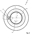
- Fig. 3 shows the rotary seal 22 and the second machine part 14 of the rotary seal arrangement 10 according to FIG Fig. 1 in an isolated frontal and partially sectioned view. It can be clearly seen that this Coil spring sealing element 34 protrudes radially in the direction of and against the sealing surface 28 from the circumferential groove 32 of the holding element 24.
- the rotary seal arrangement 10 is shown in an operating state in which the seal designed as a helical spring sealing element 34 is caused by an increased friction or an increased frictional resistance between the helical spring sealing element 34 and the sealing surface - while overcoming a frictional resistance existing between the helical spring sealing element 34 and the holding element 24 - by the in the first direction of rotation 18 ( Fig. 1 )
- Rotating second machine part 14 taken in the direction of rotation 18 and with its respective end face 48 pointing in the direction of rotation 18 is guided against the rotary stop 46 of the holding element 24 assigned to the end face 48.
- the helical spring sealing element 34 supported on the rotary stop 46 is acted upon and twisted by a torsional force resulting from the rotational movement of the second machine part 14.
- the torsion of the coil spring sealing element 34 behaves - depending on the selected spring characteristic of the coil spring element 34 - proportional to the frictional resistance between the sealing surface and the coil spring sealing element 34 lying thereon.
- the coil spring sealing element 34 is thereby in the radial direction - contrary to the elastic resilience inherent in the coil spring sealing element 34 and the radial force of the holding element 24 acting inward on the helical spring sealing element 34 and thereby reducing the surface pressure between the helical spring sealing element 34 and the sealing surface 28.
- the friction between the helical spring sealing element and the sealing surface 28 and therefore the frictional resistance is limited to a predetermined friction / a predetermined frictional resistance.
- the rotary seal 22 of the rotary seal arrangement 10 thereby has a self-protection mechanism by means of which the coil spring seal element 34 during a Operation is protected from excessive frictional (mechanical and thermal) stress.
- Fig. 6 shows the rotary seal arrangement 10 explained above in an operating state in which the rotatably mounted machine part 14 is moved in a rotational direction 18 ′ opposite to the first rotational direction and in the activated, ie twisted, state.
- the helical spring sealing element 34 of the rotary seal 22 is supported in a manner analogous to the above explanations with its end face 48 pointing in the direction of rotation 18 ′ on the associated rotary stop 46 of the holding element 24.
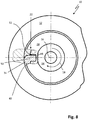
- the functional principle explained above can be according to the in the Figures 7 and 8th Embodiment of the invention shown can also be realized in a rotary seal assembly 10 with a radially outer sealing rotary seal 22.
- the holding element 24 is fastened to a seal holding structure 26 of the second, that is to say to the machine part 14 arranged on the inside in the radial direction.
- the sealing element designed as a helical spring sealing element 34 lies on the sealing surface 28 of the first machine part 12 in a sealing manner.
- the coil spring sealing element 34 is relieved to protect against excessive stress due to friction on the sealing surface 28 by means of a torsion-related and radially inward compression in its contact with the sealing surface.
- the helical spring sealing element 34 is fixed to the holding element 24 with its free end section 50 directed in the direction of rotation 18.
- the free end section 50 can be angled and engage in a recess 52 in the groove base 40, as shown in FIG Fig. 8 is shown. It is also conceivable that the free end section 50 of the helical spring sealing element 34 engages in a recess in one of the two groove flanks 42 of the circumferential groove 34 or is fastened in another way to the holding element 24.
- the coil spring sealing element 34 is possibly against a frictional resistance existing between the coil spring sealing element and the holding element - due to the fact that in the first direction of rotation ( Fig. 1 ) Rotating the second machine part 12 taken in the direction of rotation and twisted in such a way that the coil spring sealing element 34 in the radial direction - counter to the elastic resilience inherent in the coil spring sealing element 34 (radially outward restoring force) and any radial force of the holding element 24 acting on the coil spring sealing element 34 - in is compressed in the radial direction, so that the contact surface pressure 38 between the coil spring sealing element 34 and the sealing surface 28 is reduced.
- the coil spring sealing element 34 can in particular consist of PTFE (polytetrafluoroethylene) or another suitable plastic or a composite material.
- the holding element 24 is preferably made of a rubber-elastic deformable material, for example PU (polyurethane) or the like.
- the coil spring sealing elements 34 of the above in connection with the Figures 1 to 8 can each have one or more grooves or grooves, which can be arranged in a screw or spiral manner with respect to the axis of rotation 16.
- a return of a fluid for example lubricating oil, arranged in the sealing gap can be achieved via the helical spring sealing element 34.
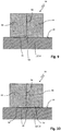
- a groove or grooves 54 can be aligned in the radial direction with the spiral contact area 56 of the individual turns 44 of the helical spring sealing element 34.
- spiral groove / grooves 54 in the circumferential surface 36 of the helical spring element 34 can be arranged axially offset from the contact area 56, as shown in FIG Fig. 10 is shown.
- spiral grooves / grooves 54 has an incline (in Fig. 10 not designated) on, which corresponds to the slope of the coil spring element 34.
- the amount of lubricating oil that can be returned can be increased further by several of the aforementioned grooves / grooves 54.
Landscapes
- Engineering & Computer Science (AREA)
- General Engineering & Computer Science (AREA)
- Mechanical Engineering (AREA)
- Sealing Devices (AREA)
- Mechanical Sealing (AREA)
- Sealing With Elastic Sealing Lips (AREA)
Applications Claiming Priority (2)
| Application Number | Priority Date | Filing Date | Title |
|---|---|---|---|
| DE102015226691.5A DE102015226691A1 (de) | 2015-12-23 | 2015-12-23 | Rotationsdichtungsanordnung und Rotationsdichtung mit Schraubenfederdichtelement |
| PCT/EP2016/080748 WO2017108496A1 (de) | 2015-12-23 | 2016-12-13 | Rotationsdichtungsanordnung und rotationsdichtung mit schraubenfederdichtelement |
Publications (2)
| Publication Number | Publication Date |
|---|---|
| EP3394482A1 EP3394482A1 (de) | 2018-10-31 |
| EP3394482B1 true EP3394482B1 (de) | 2020-03-18 |
Family
ID=57588999
Family Applications (1)
| Application Number | Title | Priority Date | Filing Date |
|---|---|---|---|
| EP16815788.1A Active EP3394482B1 (de) | 2015-12-23 | 2016-12-13 | Rotationsdichtungsanordnung mit schraubenfederdichtelement |
Country Status (8)
Families Citing this family (4)
| Publication number | Priority date | Publication date | Assignee | Title |
|---|---|---|---|---|
| CN109578602B (zh) * | 2018-11-21 | 2020-02-11 | 浙江工贸职业技术学院 | 一种先导式截止阀 |
| US20230210188A1 (en) * | 2020-05-15 | 2023-07-06 | Philip Morris Products S.A. | Aerosol-generating article comprising a liquid reservoir and a transferrable sealing member |
| CN112940888A (zh) * | 2021-03-19 | 2021-06-11 | 永州江嘉生物科技有限公司 | 一种用于小曲酒酿造的密封机构 |
| US12352355B2 (en) * | 2022-11-15 | 2025-07-08 | Goodrich Corporation | System and method for monitoring gasket sealing health |
Family Cites Families (12)
| Publication number | Priority date | Publication date | Assignee | Title |
|---|---|---|---|---|
| US3442518A (en) * | 1966-05-11 | 1969-05-06 | Langford W Henshaw | Packing for stuffing boxes |
| US4501431A (en) * | 1983-12-19 | 1985-02-26 | Chicago Rawhide Manufacturing Company | Composite teflon helix seal |
| JP2769523B2 (ja) * | 1994-01-31 | 1998-06-25 | 株式会社キッツ | パッキンリングの構造とその製造方法並びにそれを用いたシール装置 |
| CA2082567C (en) * | 1991-11-11 | 2002-01-22 | William John Dartnall | Seal |
| RU2037077C1 (ru) * | 1993-10-25 | 1995-06-09 | Борис Семенович Захаров | Механическое уплотнение |
| CN1097187C (zh) * | 1994-11-16 | 2002-12-25 | 德雷瑟-兰德公司 | 轴密封 |
| CN2237757Y (zh) * | 1995-09-26 | 1996-10-16 | 莫渐华 | 一种橡胶油封 |
| CN2408308Y (zh) * | 1999-12-13 | 2000-11-29 | 张秀芹 | 一种弹簧圈式密封填料 |
| US7419165B2 (en) * | 2004-08-18 | 2008-09-02 | Federal-Mogul World Wide, Inc. | Seal assembly and method of manufacturing the same |
| GB0912379D0 (en) * | 2009-07-17 | 2009-08-26 | Rolls Royce Plc | Rotary coupling |
| CN202937445U (zh) * | 2012-02-25 | 2013-05-15 | 昱曦机械高新科技有限公司 | 活塞具有金属密封环的轴向活塞泵 |
| KR20130006701U (ko) * | 2012-05-14 | 2013-11-22 | 장경태 | 심해 잠수정 용 금속 코일 프로펠러 샤프트 씰. |
-
2015
- 2015-12-23 DE DE102015226691.5A patent/DE102015226691A1/de not_active Withdrawn
-
2016
- 2016-12-13 EP EP16815788.1A patent/EP3394482B1/de active Active
- 2016-12-13 HK HK18113844.1A patent/HK1254551A1/zh unknown
- 2016-12-13 CN CN201680075485.8A patent/CN108474478A/zh active Pending
- 2016-12-13 JP JP2018532412A patent/JP6820931B2/ja active Active
- 2016-12-13 KR KR1020187021257A patent/KR20180117600A/ko not_active Ceased
- 2016-12-13 WO PCT/EP2016/080748 patent/WO2017108496A1/de active Search and Examination
-
2018
- 2018-06-21 US US16/015,136 patent/US20180299013A1/en not_active Abandoned
Non-Patent Citations (1)
| Title |
|---|
| None * |
Also Published As
| Publication number | Publication date |
|---|---|
| HK1254551A1 (zh) | 2019-07-19 |
| JP2018538496A (ja) | 2018-12-27 |
| JP6820931B2 (ja) | 2021-01-27 |
| KR20180117600A (ko) | 2018-10-29 |
| WO2017108496A1 (de) | 2017-06-29 |
| CN108474478A (zh) | 2018-08-31 |
| DE102015226691A1 (de) | 2017-06-29 |
| EP3394482A1 (de) | 2018-10-31 |
| US20180299013A1 (en) | 2018-10-18 |
Similar Documents
| Publication | Publication Date | Title |
|---|---|---|
| EP3394482B1 (de) | Rotationsdichtungsanordnung mit schraubenfederdichtelement | |
| EP0525288B1 (de) | Kassettendichtung | |
| DE69929554T2 (de) | Lagervorrichtung mit sphärischen Lagerflächen | |
| EP1989467B1 (de) | Zahnradanordnung | |
| EP3775457B1 (de) | Antriebsvorrichtung | |
| DE102011082097A1 (de) | Flexibeleingriff-Zahnradgetriebe | |
| DE102008028115A1 (de) | Lager | |
| DE102006060681B3 (de) | Dichtung für Gewindetrieb | |
| DE2756403A1 (de) | Dichtung | |
| DE102015209598B4 (de) | Planetenwälzgewindetrieb | |
| EP2824362A1 (de) | Drehschwingungsdämpfer | |
| WO2008141969A1 (de) | Rundtischlager | |
| DE102013215865B4 (de) | Linearantrieb | |
| EP3534031B1 (de) | Nachstellvorrichtung für eine scheibenbremse | |
| EP3385499A1 (de) | Schneidrolle | |
| DE2453645B2 (de) | Elastische Verbindungsvorrichtung für zwei im wesentlichen koaxiale Teile | |
| DE102012223903A1 (de) | Dichtung für ein Wälzlager und Wälzlager | |
| DE102008029642A1 (de) | Tellerfederanordnung | |
| EP3737879A1 (de) | Dichtung | |
| DE4113738A1 (de) | Zellenradschleuse mit einer dichtungsanordnung zwischen der zellenradseitenscheibe und dem zugehoerigen lagerdeckel | |
| DE102007034812A1 (de) | Dichteinrichtung für ein Drehlager | |
| EP3417192B1 (de) | Wellendichtung | |
| DE102019122275A1 (de) | Einstellbares Gleitlager für eine Lenksäule | |
| DE1911794A1 (de) | Dichtung fuer oszillierende Drehbewegungen ausfuehrende Lager | |
| DE102022131223B4 (de) | Dichtungseinheit für eine Welle |
Legal Events
| Date | Code | Title | Description |
|---|---|---|---|
| STAA | Information on the status of an ep patent application or granted ep patent |
Free format text: STATUS: UNKNOWN |
|
| STAA | Information on the status of an ep patent application or granted ep patent |
Free format text: STATUS: THE INTERNATIONAL PUBLICATION HAS BEEN MADE |
|
| PUAI | Public reference made under article 153(3) epc to a published international application that has entered the european phase |
Free format text: ORIGINAL CODE: 0009012 |
|
| STAA | Information on the status of an ep patent application or granted ep patent |
Free format text: STATUS: REQUEST FOR EXAMINATION WAS MADE |
|
| 17P | Request for examination filed |
Effective date: 20180523 |
|
| AK | Designated contracting states |
Kind code of ref document: A1 Designated state(s): AL AT BE BG CH CY CZ DE DK EE ES FI FR GB GR HR HU IE IS IT LI LT LU LV MC MK MT NL NO PL PT RO RS SE SI SK SM TR |
|
| AX | Request for extension of the european patent |
Extension state: BA ME |
|
| DAV | Request for validation of the european patent (deleted) | ||
| DAX | Request for extension of the european patent (deleted) | ||
| GRAP | Despatch of communication of intention to grant a patent |
Free format text: ORIGINAL CODE: EPIDOSNIGR1 |
|
| STAA | Information on the status of an ep patent application or granted ep patent |
Free format text: STATUS: GRANT OF PATENT IS INTENDED |
|
| INTG | Intention to grant announced |
Effective date: 20191007 |
|
| GRAS | Grant fee paid |
Free format text: ORIGINAL CODE: EPIDOSNIGR3 |
|
| GRAA | (expected) grant |
Free format text: ORIGINAL CODE: 0009210 |
|
| STAA | Information on the status of an ep patent application or granted ep patent |
Free format text: STATUS: THE PATENT HAS BEEN GRANTED |
|
| AK | Designated contracting states |
Kind code of ref document: B1 Designated state(s): AL AT BE BG CH CY CZ DE DK EE ES FI FR GB GR HR HU IE IS IT LI LT LU LV MC MK MT NL NO PL PT RO RS SE SI SK SM TR |
|
| REG | Reference to a national code |
Ref country code: GB Ref legal event code: FG4D Free format text: NOT ENGLISH |
|
| REG | Reference to a national code |
Ref country code: DE Ref legal event code: R096 Ref document number: 502016009220 Country of ref document: DE |
|
| REG | Reference to a national code |
Ref country code: AT Ref legal event code: REF Ref document number: 1246265 Country of ref document: AT Kind code of ref document: T Effective date: 20200415 Ref country code: IE Ref legal event code: FG4D Free format text: LANGUAGE OF EP DOCUMENT: GERMAN |
|
| PG25 | Lapsed in a contracting state [announced via postgrant information from national office to epo] |
Ref country code: NO Free format text: LAPSE BECAUSE OF FAILURE TO SUBMIT A TRANSLATION OF THE DESCRIPTION OR TO PAY THE FEE WITHIN THE PRESCRIBED TIME-LIMIT Effective date: 20200618 Ref country code: RS Free format text: LAPSE BECAUSE OF FAILURE TO SUBMIT A TRANSLATION OF THE DESCRIPTION OR TO PAY THE FEE WITHIN THE PRESCRIBED TIME-LIMIT Effective date: 20200318 Ref country code: FI Free format text: LAPSE BECAUSE OF FAILURE TO SUBMIT A TRANSLATION OF THE DESCRIPTION OR TO PAY THE FEE WITHIN THE PRESCRIBED TIME-LIMIT Effective date: 20200318 |
|
| REG | Reference to a national code |
Ref country code: NL Ref legal event code: MP Effective date: 20200318 |
|
| PG25 | Lapsed in a contracting state [announced via postgrant information from national office to epo] |
Ref country code: LV Free format text: LAPSE BECAUSE OF FAILURE TO SUBMIT A TRANSLATION OF THE DESCRIPTION OR TO PAY THE FEE WITHIN THE PRESCRIBED TIME-LIMIT Effective date: 20200318 Ref country code: SE Free format text: LAPSE BECAUSE OF FAILURE TO SUBMIT A TRANSLATION OF THE DESCRIPTION OR TO PAY THE FEE WITHIN THE PRESCRIBED TIME-LIMIT Effective date: 20200318 Ref country code: GR Free format text: LAPSE BECAUSE OF FAILURE TO SUBMIT A TRANSLATION OF THE DESCRIPTION OR TO PAY THE FEE WITHIN THE PRESCRIBED TIME-LIMIT Effective date: 20200619 Ref country code: BG Free format text: LAPSE BECAUSE OF FAILURE TO SUBMIT A TRANSLATION OF THE DESCRIPTION OR TO PAY THE FEE WITHIN THE PRESCRIBED TIME-LIMIT Effective date: 20200618 Ref country code: HR Free format text: LAPSE BECAUSE OF FAILURE TO SUBMIT A TRANSLATION OF THE DESCRIPTION OR TO PAY THE FEE WITHIN THE PRESCRIBED TIME-LIMIT Effective date: 20200318 |
|
| REG | Reference to a national code |
Ref country code: LT Ref legal event code: MG4D |
|
| PG25 | Lapsed in a contracting state [announced via postgrant information from national office to epo] |
Ref country code: NL Free format text: LAPSE BECAUSE OF FAILURE TO SUBMIT A TRANSLATION OF THE DESCRIPTION OR TO PAY THE FEE WITHIN THE PRESCRIBED TIME-LIMIT Effective date: 20200318 |
|
| RAP2 | Party data changed (patent owner data changed or rights of a patent transferred) |
Owner name: TRELLEBORG SEALING SOLUTIONS GERMANY GMBH |
|
| PG25 | Lapsed in a contracting state [announced via postgrant information from national office to epo] |
Ref country code: IS Free format text: LAPSE BECAUSE OF FAILURE TO SUBMIT A TRANSLATION OF THE DESCRIPTION OR TO PAY THE FEE WITHIN THE PRESCRIBED TIME-LIMIT Effective date: 20200718 Ref country code: RO Free format text: LAPSE BECAUSE OF FAILURE TO SUBMIT A TRANSLATION OF THE DESCRIPTION OR TO PAY THE FEE WITHIN THE PRESCRIBED TIME-LIMIT Effective date: 20200318 Ref country code: SK Free format text: LAPSE BECAUSE OF FAILURE TO SUBMIT A TRANSLATION OF THE DESCRIPTION OR TO PAY THE FEE WITHIN THE PRESCRIBED TIME-LIMIT Effective date: 20200318 Ref country code: CZ Free format text: LAPSE BECAUSE OF FAILURE TO SUBMIT A TRANSLATION OF THE DESCRIPTION OR TO PAY THE FEE WITHIN THE PRESCRIBED TIME-LIMIT Effective date: 20200318 Ref country code: SM Free format text: LAPSE BECAUSE OF FAILURE TO SUBMIT A TRANSLATION OF THE DESCRIPTION OR TO PAY THE FEE WITHIN THE PRESCRIBED TIME-LIMIT Effective date: 20200318 Ref country code: LT Free format text: LAPSE BECAUSE OF FAILURE TO SUBMIT A TRANSLATION OF THE DESCRIPTION OR TO PAY THE FEE WITHIN THE PRESCRIBED TIME-LIMIT Effective date: 20200318 Ref country code: EE Free format text: LAPSE BECAUSE OF FAILURE TO SUBMIT A TRANSLATION OF THE DESCRIPTION OR TO PAY THE FEE WITHIN THE PRESCRIBED TIME-LIMIT Effective date: 20200318 Ref country code: PT Free format text: LAPSE BECAUSE OF FAILURE TO SUBMIT A TRANSLATION OF THE DESCRIPTION OR TO PAY THE FEE WITHIN THE PRESCRIBED TIME-LIMIT Effective date: 20200812 |
|
| REG | Reference to a national code |
Ref country code: DE Ref legal event code: R097 Ref document number: 502016009220 Country of ref document: DE |
|
| PLBE | No opposition filed within time limit |
Free format text: ORIGINAL CODE: 0009261 |
|
| STAA | Information on the status of an ep patent application or granted ep patent |
Free format text: STATUS: NO OPPOSITION FILED WITHIN TIME LIMIT |
|
| PG25 | Lapsed in a contracting state [announced via postgrant information from national office to epo] |
Ref country code: ES Free format text: LAPSE BECAUSE OF FAILURE TO SUBMIT A TRANSLATION OF THE DESCRIPTION OR TO PAY THE FEE WITHIN THE PRESCRIBED TIME-LIMIT Effective date: 20200318 Ref country code: DK Free format text: LAPSE BECAUSE OF FAILURE TO SUBMIT A TRANSLATION OF THE DESCRIPTION OR TO PAY THE FEE WITHIN THE PRESCRIBED TIME-LIMIT Effective date: 20200318 Ref country code: IT Free format text: LAPSE BECAUSE OF FAILURE TO SUBMIT A TRANSLATION OF THE DESCRIPTION OR TO PAY THE FEE WITHIN THE PRESCRIBED TIME-LIMIT Effective date: 20200318 |
|
| 26N | No opposition filed |
Effective date: 20201221 |
|
| PG25 | Lapsed in a contracting state [announced via postgrant information from national office to epo] |
Ref country code: PL Free format text: LAPSE BECAUSE OF FAILURE TO SUBMIT A TRANSLATION OF THE DESCRIPTION OR TO PAY THE FEE WITHIN THE PRESCRIBED TIME-LIMIT Effective date: 20200318 |
|
| PG25 | Lapsed in a contracting state [announced via postgrant information from national office to epo] |
Ref country code: SI Free format text: LAPSE BECAUSE OF FAILURE TO SUBMIT A TRANSLATION OF THE DESCRIPTION OR TO PAY THE FEE WITHIN THE PRESCRIBED TIME-LIMIT Effective date: 20200318 |
|
| REG | Reference to a national code |
Ref country code: CH Ref legal event code: PL |
|
| PG25 | Lapsed in a contracting state [announced via postgrant information from national office to epo] |
Ref country code: MC Free format text: LAPSE BECAUSE OF FAILURE TO SUBMIT A TRANSLATION OF THE DESCRIPTION OR TO PAY THE FEE WITHIN THE PRESCRIBED TIME-LIMIT Effective date: 20200318 |
|
| REG | Reference to a national code |
Ref country code: BE Ref legal event code: MM Effective date: 20201231 |
|
| PG25 | Lapsed in a contracting state [announced via postgrant information from national office to epo] |
Ref country code: IE Free format text: LAPSE BECAUSE OF NON-PAYMENT OF DUE FEES Effective date: 20201213 Ref country code: LU Free format text: LAPSE BECAUSE OF NON-PAYMENT OF DUE FEES Effective date: 20201213 Ref country code: FR Free format text: LAPSE BECAUSE OF NON-PAYMENT OF DUE FEES Effective date: 20201231 |
|
| PG25 | Lapsed in a contracting state [announced via postgrant information from national office to epo] |
Ref country code: CH Free format text: LAPSE BECAUSE OF NON-PAYMENT OF DUE FEES Effective date: 20201231 Ref country code: LI Free format text: LAPSE BECAUSE OF NON-PAYMENT OF DUE FEES Effective date: 20201231 |
|
| PG25 | Lapsed in a contracting state [announced via postgrant information from national office to epo] |
Ref country code: TR Free format text: LAPSE BECAUSE OF FAILURE TO SUBMIT A TRANSLATION OF THE DESCRIPTION OR TO PAY THE FEE WITHIN THE PRESCRIBED TIME-LIMIT Effective date: 20200318 Ref country code: MT Free format text: LAPSE BECAUSE OF FAILURE TO SUBMIT A TRANSLATION OF THE DESCRIPTION OR TO PAY THE FEE WITHIN THE PRESCRIBED TIME-LIMIT Effective date: 20200318 Ref country code: CY Free format text: LAPSE BECAUSE OF FAILURE TO SUBMIT A TRANSLATION OF THE DESCRIPTION OR TO PAY THE FEE WITHIN THE PRESCRIBED TIME-LIMIT Effective date: 20200318 |
|
| PG25 | Lapsed in a contracting state [announced via postgrant information from national office to epo] |
Ref country code: MK Free format text: LAPSE BECAUSE OF FAILURE TO SUBMIT A TRANSLATION OF THE DESCRIPTION OR TO PAY THE FEE WITHIN THE PRESCRIBED TIME-LIMIT Effective date: 20200318 Ref country code: AL Free format text: LAPSE BECAUSE OF FAILURE TO SUBMIT A TRANSLATION OF THE DESCRIPTION OR TO PAY THE FEE WITHIN THE PRESCRIBED TIME-LIMIT Effective date: 20200318 |
|
| PG25 | Lapsed in a contracting state [announced via postgrant information from national office to epo] |
Ref country code: BE Free format text: LAPSE BECAUSE OF NON-PAYMENT OF DUE FEES Effective date: 20201231 |
|
| PGFP | Annual fee paid to national office [announced via postgrant information from national office to epo] |
Ref country code: GB Payment date: 20221222 Year of fee payment: 7 |
|
| REG | Reference to a national code |
Ref country code: AT Ref legal event code: MM01 Ref document number: 1246265 Country of ref document: AT Kind code of ref document: T Effective date: 20211213 |
|
| PG25 | Lapsed in a contracting state [announced via postgrant information from national office to epo] |
Ref country code: AT Free format text: LAPSE BECAUSE OF NON-PAYMENT OF DUE FEES Effective date: 20211213 |
|
| P01 | Opt-out of the competence of the unified patent court (upc) registered |
Effective date: 20230630 |
|
| GBPC | Gb: european patent ceased through non-payment of renewal fee |
Effective date: 20231213 |
|
| PG25 | Lapsed in a contracting state [announced via postgrant information from national office to epo] |
Ref country code: GB Free format text: LAPSE BECAUSE OF NON-PAYMENT OF DUE FEES Effective date: 20231213 |
|
| PG25 | Lapsed in a contracting state [announced via postgrant information from national office to epo] |
Ref country code: GB Free format text: LAPSE BECAUSE OF NON-PAYMENT OF DUE FEES Effective date: 20231213 |
|
| PGFP | Annual fee paid to national office [announced via postgrant information from national office to epo] |
Ref country code: DE Payment date: 20241217 Year of fee payment: 9 |