EP3394401B1 - Turboréacteur avec un moyen de reprise de poussée sur le carter inter-compresseurs - Google Patents
Turboréacteur avec un moyen de reprise de poussée sur le carter inter-compresseurs Download PDFInfo
- Publication number
- EP3394401B1 EP3394401B1 EP16826089.1A EP16826089A EP3394401B1 EP 3394401 B1 EP3394401 B1 EP 3394401B1 EP 16826089 A EP16826089 A EP 16826089A EP 3394401 B1 EP3394401 B1 EP 3394401B1
- Authority
- EP
- European Patent Office
- Prior art keywords
- compressor
- inter
- case
- turbojet engine
- engine according
- Prior art date
- Legal status (The legal status is an assumption and is not a legal conclusion. Google has not performed a legal analysis and makes no representation as to the accuracy of the status listed.)
- Active
Links
Images


Classifications
-
- F—MECHANICAL ENGINEERING; LIGHTING; HEATING; WEAPONS; BLASTING
- F02—COMBUSTION ENGINES; HOT-GAS OR COMBUSTION-PRODUCT ENGINE PLANTS
- F02C—GAS-TURBINE PLANTS; AIR INTAKES FOR JET-PROPULSION PLANTS; CONTROLLING FUEL SUPPLY IN AIR-BREATHING JET-PROPULSION PLANTS
- F02C7/00—Features, components parts, details or accessories, not provided for in, or of interest apart form groups F02C1/00 - F02C6/00; Air intakes for jet-propulsion plants
- F02C7/20—Mounting or supporting of plant; Accommodating heat expansion or creep
-
- F—MECHANICAL ENGINEERING; LIGHTING; HEATING; WEAPONS; BLASTING
- F01—MACHINES OR ENGINES IN GENERAL; ENGINE PLANTS IN GENERAL; STEAM ENGINES
- F01D—NON-POSITIVE DISPLACEMENT MACHINES OR ENGINES, e.g. STEAM TURBINES
- F01D25/00—Component parts, details, or accessories, not provided for in, or of interest apart from, other groups
- F01D25/16—Arrangement of bearings; Supporting or mounting bearings in casings
- F01D25/162—Bearing supports
-
- F—MECHANICAL ENGINEERING; LIGHTING; HEATING; WEAPONS; BLASTING
- F01—MACHINES OR ENGINES IN GENERAL; ENGINE PLANTS IN GENERAL; STEAM ENGINES
- F01D—NON-POSITIVE DISPLACEMENT MACHINES OR ENGINES, e.g. STEAM TURBINES
- F01D25/00—Component parts, details, or accessories, not provided for in, or of interest apart from, other groups
- F01D25/24—Casings; Casing parts, e.g. diaphragms, casing fastenings
-
- F—MECHANICAL ENGINEERING; LIGHTING; HEATING; WEAPONS; BLASTING
- F01—MACHINES OR ENGINES IN GENERAL; ENGINE PLANTS IN GENERAL; STEAM ENGINES
- F01D—NON-POSITIVE DISPLACEMENT MACHINES OR ENGINES, e.g. STEAM TURBINES
- F01D25/00—Component parts, details, or accessories, not provided for in, or of interest apart from, other groups
- F01D25/24—Casings; Casing parts, e.g. diaphragms, casing fastenings
- F01D25/246—Fastening of diaphragms or stator-rings
-
- F—MECHANICAL ENGINEERING; LIGHTING; HEATING; WEAPONS; BLASTING
- F01—MACHINES OR ENGINES IN GENERAL; ENGINE PLANTS IN GENERAL; STEAM ENGINES
- F01D—NON-POSITIVE DISPLACEMENT MACHINES OR ENGINES, e.g. STEAM TURBINES
- F01D25/00—Component parts, details, or accessories, not provided for in, or of interest apart from, other groups
- F01D25/28—Supporting or mounting arrangements, e.g. for turbine casing
-
- F—MECHANICAL ENGINEERING; LIGHTING; HEATING; WEAPONS; BLASTING
- F02—COMBUSTION ENGINES; HOT-GAS OR COMBUSTION-PRODUCT ENGINE PLANTS
- F02K—JET-PROPULSION PLANTS
- F02K3/00—Plants including a gas turbine driving a compressor or a ducted fan
- F02K3/02—Plants including a gas turbine driving a compressor or a ducted fan in which part of the working fluid by-passes the turbine and combustion chamber
- F02K3/04—Plants including a gas turbine driving a compressor or a ducted fan in which part of the working fluid by-passes the turbine and combustion chamber the plant including ducted fans, i.e. fans with high volume, low pressure outputs, for augmenting the jet thrust, e.g. of double-flow type
- F02K3/06—Plants including a gas turbine driving a compressor or a ducted fan in which part of the working fluid by-passes the turbine and combustion chamber the plant including ducted fans, i.e. fans with high volume, low pressure outputs, for augmenting the jet thrust, e.g. of double-flow type with front fan
-
- F—MECHANICAL ENGINEERING; LIGHTING; HEATING; WEAPONS; BLASTING
- F05—INDEXING SCHEMES RELATING TO ENGINES OR PUMPS IN VARIOUS SUBCLASSES OF CLASSES F01-F04
- F05D—INDEXING SCHEME FOR ASPECTS RELATING TO NON-POSITIVE-DISPLACEMENT MACHINES OR ENGINES, GAS-TURBINES OR JET-PROPULSION PLANTS
- F05D2230/00—Manufacture
- F05D2230/60—Assembly methods
- F05D2230/64—Assembly methods using positioning or alignment devices for aligning or centring, e.g. pins
- F05D2230/642—Assembly methods using positioning or alignment devices for aligning or centring, e.g. pins using maintaining alignment while permitting differential dilatation
-
- F—MECHANICAL ENGINEERING; LIGHTING; HEATING; WEAPONS; BLASTING
- F05—INDEXING SCHEMES RELATING TO ENGINES OR PUMPS IN VARIOUS SUBCLASSES OF CLASSES F01-F04
- F05D—INDEXING SCHEME FOR ASPECTS RELATING TO NON-POSITIVE-DISPLACEMENT MACHINES OR ENGINES, GAS-TURBINES OR JET-PROPULSION PLANTS
- F05D2240/00—Components
- F05D2240/90—Mounting on supporting structures or systems
-
- F—MECHANICAL ENGINEERING; LIGHTING; HEATING; WEAPONS; BLASTING
- F05—INDEXING SCHEMES RELATING TO ENGINES OR PUMPS IN VARIOUS SUBCLASSES OF CLASSES F01-F04
- F05D—INDEXING SCHEME FOR ASPECTS RELATING TO NON-POSITIVE-DISPLACEMENT MACHINES OR ENGINES, GAS-TURBINES OR JET-PROPULSION PLANTS
- F05D2250/00—Geometry
- F05D2250/40—Movement of components
- F05D2250/41—Movement of components with one degree of freedom
-
- Y—GENERAL TAGGING OF NEW TECHNOLOGICAL DEVELOPMENTS; GENERAL TAGGING OF CROSS-SECTIONAL TECHNOLOGIES SPANNING OVER SEVERAL SECTIONS OF THE IPC; TECHNICAL SUBJECTS COVERED BY FORMER USPC CROSS-REFERENCE ART COLLECTIONS [XRACs] AND DIGESTS
- Y02—TECHNOLOGIES OR APPLICATIONS FOR MITIGATION OR ADAPTATION AGAINST CLIMATE CHANGE
- Y02T—CLIMATE CHANGE MITIGATION TECHNOLOGIES RELATED TO TRANSPORTATION
- Y02T50/00—Aeronautics or air transport
- Y02T50/60—Efficient propulsion technologies, e.g. for aircraft
Definitions
- the present invention relates to the field of aeronautical propulsion. It relates to the suspension of a turbojet from an aircraft and more particularly to the arrangement of the means ensuring the transmission or the resumption of the thrust supplied by the engine to the structure of the aircraft.
- the state of the art includes in particular the documents US-A1-2012 / 195753 , EP-A2-2 592 235 , US-A1 -2008/098717 , EP-A1-1564397 and CA-A1-2929 947 .
- a multi-flow turbojet according to a known architecture of the prior art comprises, from upstream to downstream in the direction of the air flow passing through it, a fan and a gas generator by which it is driven in rotation.
- the latter is formed of at least one compressor, an annular combustion chamber, at least one turbine and a combustion gas ejection nozzle.
- the air compressed by the blower is divided into two concentric flows: a central primary flow supplying the gas generator and a secondary flow surrounding the latter.
- the two streams can be ejected into the atmosphere separately by concentric nozzles or else be mixed downstream of the gas generator and ejected into the atmosphere through a common nozzle.
- the gas generator is a multi-barrel, for example double-barrel, gas turbine engine with two independent coaxial rotors.
- a first low pressure body includes a compressor and a turbine, connected by a first shaft
- a second high pressure body includes a compressor and a turbine connected by a second shaft coaxial with the first.
- the combustion chamber is supplied with compressed air successively by the blower, the low pressure compressor, LP, and the high pressure compressor, HP.
- the gases resulting from the combustion are successively expanded in the high pressure turbine, HP, then in the low pressure turbine, LP, before being ejected into the atmosphere by the downstream nozzle.
- the turbines set in motion by the combustion gases drive the respective compressors and the fan in rotation, the shaft of which is connected to that of the low pressure turbine, LP.
- the blower can be driven directly by the shaft of the LP body but depending on an evolution of the engines, via a speed reducer when high dilution rates are targeted, i.e. a ratio of the secondary flow to high primary air flow.
- the dilution rates are limited in particular by the peripheral speed at the head of the fan blades.
- the architectures comprising a turbofan driven by the intermediary of a speed reducer with a very high dilution ratio - or in English UHBR (ultra high bypass ratio) - partially respond to this problem by optimizing the efficiency of the turbine at a moderate blower speed.
- the motor comprises stator members to perform in particular the functions of support, of guiding the flows and of transmitting the forces.
- the axial forces pass through the intermediate casing or inter-compressors before being transmitted to the suspension.
- the motor comprises, in addition to the inter-compressor casing, an inlet casing located between the fan and the LP compressor so as to be able to support the weight of the reducer and the bearings.
- the input casing is thus designed to directly support the reduction gear, for example with an epicyclic gear train.
- the presence of the inlet casing has the consequence that the fan and the LP shaft are no longer supported by the inter-compressor casing but by the inlet casing.
- the input casing also takes up the axial forces of the fan shaft by the bearing which supports the fan shaft and the axial forces of the LP shaft by the bearing of the LP shaft.
- the two bearings are chosen so as to form axial stops and absorb the axial loads. Ball bearings are suitable for this function, but also other bearings are also suitable.
- the blower rotor can be supported by a double tapered roller bearing which substitutes for a roller bearing and a ball bearing as currently employed.
- the thrust take-up rods are, for their part, preferably kept attached to the inter-compressor casing, since their mounting on the input casing would not be advantageous. For this, it would be necessary to provide for an extension of the space in the intervein zone necessary for their integration.
- the length of the connecting rods would be increased with an impact on their mass.
- the stiffness of the connecting rods should be increased to avoid vibratory modes.
- their integration in the area of the inlet casing would conflict with the installation of equipment, such as the oil tank, the relief valve and the synchronization ring for the control of the variable-pitch stator vanes. compressor.
- the axial forces thus pass through the inlet casing and then up to the inter-compressor casing via the LP compressor which is interposed between the two casings.
- the LP compressor casing in itself has low mechanical strength and the axial forces corresponding to the thrust recovery on this casing are liable to deform it with the effect, on the one hand, of an increase in blade head clearances and a loss of efficiency and, on the other hand, a reduction in blade head clearances and a risk of rotor / stator contact.
- the low mechanical strength of the LP compressor casing can be compensated for by thickening it for the same material, resulting in a greater mass. However, as long as forces pass through it, deformations can be observed with the consequences mentioned above.
- the object of the present invention is to remedy this drawback.
- the solution of the invention therefore consists in dissociating the structural function of the casing of the first compressor from that of the outer wall of the primary air stream.
- the function of the structural shell is to transmit the forces between the two housings. While floating, the casing of the first compressor, forming the air stream wall, does not transmit any load through it.
- the casing forming a duct wall is connected in a floating manner to one of the two inlet and inter-compressor casings by a clearance connection.
- the structural strain ferrule is attached to the input casing to which it is welded. It is bolted downstream to the inter-compressor casing.
- the structural strain ferrule is attached by being bolted both to the inlet casing and to the inter-compressor casing.
- the input casing comprises a VSV (acronym for the English Variable Stator Vane ) ferrule supporting variable-pitch stator fins
- VSV ferrule is provided with longitudinal reinforcing ribs.
- the housing of the floating compressor is connected to one of the two inlet and inter-compressor housings with a floating connection with axial play. It also preferably has radial play.
- the connection comprises a first flange covering with play a second flange.
- the floating connection comprises a seal, isolating a primary stream from the ambient air.
- the inter-compressor casing comprises two radial flanges arranged transversely with respect to the axis, the two flanges being connected by ribs oriented in the axis. More particularly, the inter-compressor casing comprises arms passing through a primary duct, said ribs are situated in the extension of said arms.
- the means for attaching the thrust take-up rods are attached to one of the two flanges.
- the invention relates in particular to a turbojet whose fan is driven by a LP turbine and which comprises a speed reducer between a shaft of the LP turbine and the fan.
- the reduction gear is for example made up of an epicyclic gear train.
- the input housing is arranged to form a support for the speed reduction mechanism. At least part of the bearings supporting the fan shaft and the LP shaft, respectively, in the input housing are able to form axial stops.
- the figure 1 shows a turbojet 1 with, from upstream to downstream, a fan 2 and a double-body gas generator formed of a first compressor 3, a second compressor 4, a combustion chamber 5, and two turbines in series 6 and 7.
- the first compressor forms with the turbine 7 to which it is connected by a turbine shaft 71, the low pressure LP body.
- the second compressor 4 forms with the turbine 6 to which it is connected by a shaft 61, the high pressure HP body.
- the fixed structural members, ensuring the transmission of forces from the engine to the suspension include: the input casing 8 located at the inlet of the gas generator between the blower 2 and the LP compressor 3, the inter-compressor casing 9 between the LP compressor 3 and the HP compressor 4, as well as the exhaust casing 10, downstream.
- the shaft 21 of the fan is rotatably mounted in two bearings 22 and 23, the first of which is for example a roller and the second 23, near the housing, is for example ball and forms an axial thrust bearing.
- the shaft 21 is connected to the shaft 71 of the LP turbine 7 through a speed reducer 75, with an epicyclic gear train.
- This shaft 71 is integral with the rotor of the LP compressor 3 which is rotatably mounted in the input casing 8 by means of a bearing for example ball 35.
- the three bearings 22, 23 and 35 as well as the train of gears 75 are mounted in the hub 80 of the input housing 8 and supported by it.
- the input casing takes up the axial forces of the fan shaft with the ball bearing 23 of the fan shaft and the axial forces of the LP shaft with the ball bearing 35 of the LP shaft.
- From the hub 80 of the inlet casing 8 extend a plurality of radial arms 81 which pass through the vein of the primary flow and are interconnected by an annular part 82, interposed between the primary vein and the secondary vein. From this intermediate annular part 82 extend a plurality of radial arms 83 passing through the secondary duct and connecting the intermediate part 82 to the fan casing 24. Means for attaching to the structure of the aircraft are optionally provided in the extension of the arm 83 on the blower housing.
- the inter-compressor casing 9 is located immediately downstream of the LP compressor 3 and upstream of the HP compressor 4. It comprises a hub 90 through which the LP shaft 71 passes. This hub forms a support for the bearing 42 in which it is supported. the end journal of the rotor of the HP compressor 4. From the hub 90 extend a plurality of radial arms 91 passing through the primary stream. The arms 91 are interconnected by an annular part 92. This annular part 92 of the inter-compressor casing is the seat of the fasteners 95a for the thrust return rods 95, arranged to transmit the axial thrust forces to the engine suspension. .
- An example of an inter-compressor housing is described in the application for patent FR A 3 007 458 on behalf of the present applicant.
- annular part 92 of the casing 9 is formed mainly of a ferrule 92v defining the radially outer wall of the primary duct at this level, and from which extend two transverse radial flanges with respect to the axis of the engine, one upstream 92a, the other downstream 92b.
- Axial ribs 92n distributed around the axis connect the two walls 92a and 92b.
- the ribs are arranged in the extension of the radial arms 91.
- a structural strain ferrule 32 connects the two parts, spacer 82 and annular 92, of the two casings 8 and 9.
- the structural strain ferrule 32 is optionally attached to the input casing 8.
- the figure 4 shows in section the LP compressor between the inlet casing 8 and the inter-compressor casing 9.
- the input casing has an 8vsv ferrule in the axial extension of the 82v ferrule.
- the variable-pitch VSV stator vanes are pivotally mounted in this 8vsv ferrule and connected to a synchronization ring 37 by appropriate control levers 36.
- the structural ferrule 32 is welded at 32a along the downstream edge of the 8vsv ferrule. Downstream, the shell 32 is bolted at 32b to the upstream flange 92a of the inter-compressor casing.
- the upstream flange 92a, the ribs 92n allowing the horizontal component of the thrust of the fan to be taken up, the sleeve 92v and the downstream flange 92b form a rigid one-piece assembly.
- the ferrule 32 forms a rigid connection between the two housings 8 and 9. In this way, the axial forces exerted on the thrust bearings 23 and 35 are transmitted via the input casing 8 to the inter-compressor casing 9 and to the thrust pick-up connecting rods 95.
- the compressor casing 31 forms the casing inside which the mobile blades of the LP compressor 3 rotate; to this end, it comprises the wheels of radial stator vanes, forming rectifiers, for guiding the air flow between the stages of the compressor as well as the rings connecting the said ones.
- the casing is according to the embodiment shown, bolted at 31b, downstream, to the flange 92a of the inter-compressor casing. It is connected upstream to the 8vsv shell by a floating link 31a.
- An example of a floating link can be seen in detail on the figure 5 .
- the housing 31 is extended by a first axial flange 31a1.
- the first flange is annular and covers a corresponding second flange forming the downstream edge of the 8vsv ferrule.
- An axial clearance Ja is provided between the casing 31 and the downstream flange of the 8vsv ferrule.
- a radial clearance Jr is also provided between the axial flange 31a1 and the ferrule 8vsv.
- a seal 31a2 is arranged between the two parts so as to prevent air leaks from the primary air stream to the ambient air.
- the seal 31a2 here has the shape of a segment housed in an internal radial groove of the axial flange 31a1.
- Link 31a is floating thanks to the Ja and Jr. games.
- the internal flange formed by the downstream edge of the ferrule 8vsv is overlapped by an external flange 31a1 to maintain the tightness of the duct while allowing axial play.
- the external flange performs a step to ensure continuity of the vein.
- the slot induced by the step has a limited length in order to limit the losses but sufficient to compensate for the variations in spacing between the inlet casing and the inter-compressor casing.
- the pressure in this low-pressure compressor is still low compared to the pressures that may prevail in other part of the engine, such as the high-pressure compressor or the high-pressure turbine, the losses induced by this non-emerging slot are quite low.
- the temperature differences between hot and cold engine are in this zone quite low compared to hot parts of the engine such as the high pressure compressor or the high turbine. pressure, which again limits the necessary size of the axial play which is here of the order of a few millimeters.
- the radial play is determined so as, on the one hand, to be effectively compensated by the seal and to limit the volume of the slot cavity and on the other hand to compensate for the misalignment between the inlet housing and the inter-compressor casing.
- the radial play is of the order of a millimeter.
- the seal compensates for the radial clearance Jr in order to avoid air leaks from the primary air stream to the outside of the compressor, and in particular to the compartment surrounding the compressor which is not suitable for receiving this flow. These possible leaks would also cause compressor efficiency losses.
- the figure 6 shows an alternative embodiment of a floating casing.
- the floating link 31'a is, in this variant, provided on the downstream edge of the casing 31.
- the arrangement of the figure 5 is repeated mutatis mutandis.
- the axial flange of the casing 31 (idem) surrounds a corresponding axial flange of the inter-compressor casing 9 while providing axial play and radial play. A proper gasket prevents leakage through these clearances.
- the link 31'b upstream is bolted.
- the figure 7 shows another variant. It relates to the structural shell 32.
- the upstream connection of the structural shell to the 8vsv shell is bolted 32a instead of being welded.
- the assembly of the casing 31 of the LP compressor 3 remains floating with a connection bolted on one side, here upstream, and floating on the other side, here downstream.
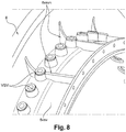
- the figure 8 shows the detail of the 8vsv ferrule of the VSV fins.
- the VSV fins are not shown, only the pivot housings are shown.
- longitudinal 8vsvn ribs are arranged on the outer face of the shell parallel to the axis. These ribs contribute to the transmission of axial forces between the input casing 8 and the structural force ferrule 32.
Landscapes
- Engineering & Computer Science (AREA)
- Mechanical Engineering (AREA)
- General Engineering & Computer Science (AREA)
- Chemical & Material Sciences (AREA)
- Combustion & Propulsion (AREA)
- Structures Of Non-Positive Displacement Pumps (AREA)
Description
- La présente invention concerne le domaine de la propulsion aéronautique. Elle porte sur la suspension d'un turboréacteur à un aéronef et plus particulièrement sur l'agencement des moyens assurant la transmission ou la reprise de la poussée fournie par le moteur à la structure de l'aéronef.
- L'état de la technique comprend notamment les documents
US-A1-2012/195753 ,EP-A2-2 592 235 ,US-A1 -2008/098717 ,EP-A1-1564397 etCA-A1-2929 947 . - Un turboréacteur multiflux conforme à une architecture connue de l'art antérieur comprend, d'amont en aval dans le sens du flux d'air le traversant, une soufflante et un générateur de gaz par lequel il est entraîné en rotation. Ce dernier est formé d'au moins un compresseur, une chambre de combustion annulaire, au moins une turbine et une tuyère d'éjection des gaz de combustion. L'air comprimé par la soufflante est divisé en deux flux concentriques : un flux primaire central alimentant le générateur de gaz et un flux secondaire entourant ce dernier. Les deux flux peuvent être éjectés dans l'atmosphère séparément par des tuyères concentriques ou bien être mélangés en aval du générateur de gaz et éjectés dans l'atmosphère à travers une tuyère commune.
- Le générateur de gaz est un moteur à turbine à gaz multi-corps, par exemple à double corps, avec deux rotors indépendants coaxiaux. Un premier corps à basse pression comprend un compresseur et une turbine, reliés par un premier arbre, un second corps à haute pression comprend un compresseur et une turbine reliés par un second arbre coaxial au premier. La chambre de combustion est alimentée par l'air comprimé successivement par la soufflante, le compresseur à basse pression, BP, et le compresseur à haute pression, HP. Les gaz issus de la combustion sont détendus successivement dans la turbine à haute pression, HP, puis dans la turbine à basse pression, BP, avant d'être éjectés dans l'atmosphère par la tuyère aval. Les turbines mises en mouvement par les gaz de combustion entraînent en rotation les compresseurs respectifs et la soufflante dont l'arbre est relié à celui de la turbine à basse pression, BP. La soufflante peut être entraînée directement par l'arbre du corps BP mais selon une évolution des moteurs, par l'intermédiaire d'un réducteur de vitesse lorsque sont visés des taux de dilution élevés, c'est à dire un rapport du flux secondaire sur le flux d'air primaire élevé. En effet, dans les turboréacteurs conventionnels avec une turbine liée directement à la soufflante, les taux de dilution sont limités notamment par la vitesse périphérique en tête des aubes de soufflante. Les architectures comprenant une turbosoufflante entraînée par l'intermédiaire d'un réducteur de vitesse avec un taux de dilution très élevé - ou en anglais UHBR (ultra high bypass ratio) - répondent partiellement à ce problème en optimisant l'efficacité de la turbine à un régime de soufflante modéré.
- Outre les rotors, le moteur comprend des organes statoriques pour assurer notamment les fonctions de support, de guidage des flux et de transmission des efforts.
- Dans les turboréacteurs à double flux, une grande partie de la poussée est réalisée par le flux secondaire. La force de traction exercée par l'air ambiant sur le moteur s'applique en partie sur les aubes de soufflante, en partie sur les parois de tuyère. Le chemin des efforts depuis la soufflante est le suivant : les efforts axiaux appliqués sur les aubes de soufflante sont transmis par un palier de butée vers les parties fixes du moteur, puis remontés vers les suspensions du moteur que sont en particulier les deux bielles de reprise de poussée. Ces bielles sont communément situées dans la zone inter-veines, et les chapes de fixation des bielles sont angulairement positionnées à environ 45° du plan vertical. Il s'agit ici de la reprise des efforts axiaux de la poussée créée par la soufflante. Les autres efforts : reprise de couple ou efforts sur les axes transversaux suivent des chemins différents qui ne sont pas concernés par la présente demande de brevet.
- Dans cette architecture, les efforts axiaux passent par le carter intermédiaire ou inter-compresseurs avant d'être transmis à la suspension.
- Sur un moteur à réducteur de vitesse entre l'arbre de turbine et celui de la soufflante, avec les architectures à taux de dilution élevé, UHBR cité plus haut, le chemin des efforts est agencé différemment.
- Dans ce type d'architecture, le moteur comprend en plus du carter inter-compresseurs, un carter d'entrée situé entre la soufflante et le compresseur BP de manière à pouvoir supporter le poids du réducteur et les paliers. Le carter d'entrée est ainsi conçu pour supporter directement le réducteur, par exemple à train d'engrenages épicycloïdal. La présence du carter d'entrée a pour conséquence que la soufflante et l'arbre BP ne sont plus supportés par le carter inter-compresseurs mais par le carter d'entrée. Il s'ensuit que le carter d'entrée reprend également les efforts axiaux de l'arbre de soufflante par le palier qui supporte l'arbre de soufflante et les efforts axiaux de l'arbre BP par le palier de l'arbre BP. Il est à noter que les deux paliers sont choisis de manière à former des butées axiales et absorber les charges axiales. Des paliers à billes conviennent pour assurer cette fonction mais aussi d'autres paliers conviennent également. Par exemple, le rotor de soufflante peut être supporté par un palier à double rouleaux coniques qui vient en substitution d'un palier à rouleaux et d'un palier à billes tels que couramment employés.
- Les bielles de reprise de poussée sont, quant à elles, de préférence maintenues attachées au carter inter-compresseurs, car leur montage sur le carter d'entrée ne serait pas avantageux. Pour cela il faudrait prévoir une extension de l'espace dans la zone inter-veines nécessaire à leur intégration. La longueur des bielles en serait accrue avec un impact sur leur masse. Par ailleurs, la raideur des bielles serait à augmenter pour éviter les modes vibratoires. Enfin, leur intégration dans la zone du carter d'entrée viendrait en conflit avec l'installation des équipements, tels que le réservoir d'huile, la vanne de décharge et l'anneau de synchronisation de la commande des ailettes de stator à calage variable du compresseur.
- Dans une telle architecture, les efforts axiaux passent ainsi par le carter d'entrée puis jusqu'au carter inter-compresseurs par le compresseur BP qui est interposé entre les deux carters. Cela n'est pas sans conséquence : le carter du compresseur BP a en soi une faible tenue mécanique et les efforts axiaux correspondant à la reprise de poussée sur ce carter sont susceptibles de le déformer avec pour effet, d'un côté, une augmentation des jeux en tête d'aube et une perte de rendement et, de l'autre côté, une diminution des jeux en tête d'aube et un risque de contact rotor/stator.
- La faible tenue mécanique du carter du compresseur BP peut-être compensée par un épaississement de celui-ci pour un même matériau avec pour conséquence une masse plus importante. Cependant, tant que des efforts y transitent, des déformations peuvent être observées avec les conséquences citées ci-dessus.
- La présente invention a pour objectif de remédier à cet inconvénient.
- On parvient à réaliser cet objectif, avec un turboréacteur multiflux comprenant les caractéristiques de la revendication 1.
- La solution de l'invention consiste donc à dissocier la fonction structurale du carter du premier compresseur de celle de paroi extérieure de la veine d'air primaire. La virole structurale a pour fonction de transmettre les efforts entre les deux carters. En étant flottant, le carter du premier compresseur, formant la paroi de veine d'air, ne transmet aucune charge à travers lui. En particulier le carter formant une paroi de veine, est relié de manière flottante à l'un des deux carters d'entrée et inter-compresseurs par une liaison à jeu.
- Ainsi par ce dispositif, d'une part, on s'affranchit de l'obligation de renforcer le carter du compresseur, d'autre part on élimine les efforts sur le carter susceptibles de causer des déformations affectant le rendement du compresseur.
- Par ailleurs, le dispositif permet de reprendre tous les efforts appelés à transiter entre les carters. Il s'agit des
- efforts axiaux correspondant à la reprise de la poussée,
- des efforts tranchants que sont le poids du moteur ou les efforts inertiels du corps HP suspendu à ses extrémités,
- le couple de torsion sur l'axe moteur,
- le couple de flexion résultant du poids ou des efforts inertiels du corps HP suspendu à ses extrémités.
- La reprise des efforts autres qu'axiaux permet d'améliorer la situation mécanique du moteur, en limitant par exemple la déformation du corps HP.
- Conformément à un mode de réalisation, la virole structurale d'efforts est rapportée sur le carter d'entrée auquel elle est soudée. Elle est boulonnée en aval sur le carter inter-compresseurs.
- Selon une variante de réalisation, la virole structurale d'efforts est rapportée en étant boulonnée à la fois sur le carter d'entrée et sur le carter inter-compresseurs.
- Lorsque le carter d'entrée comprend une virole VSV (acronyme de l'anglais Variable Stator Vane) supportant des ailettes de stator à calage variable, ladite virole VSV est pourvue de nervures longitudinales de renfort.
- Conformément à une autre caractéristique, le carter du compresseur flottant est relié à l'un des deux carters d'entrée et inter-compresseurs avec une liaison flottante à jeu axial. Il présente en outre de préférence un jeu radial. De préférence la liaison comprend une première bride recouvrant avec jeu une seconde bride.
- Egalement pour éviter toute fuite d'air, la liaison flottante comprend un joint d'étanchéité, isolant une veine primaire de l'air ambiant.
- De préférence comme cela est décrit dans la demande de
brevet FR A 3 007 458 - Enfin, cette solution permet de faire transiter tout type d'effort, en limitant l'encombrement du dispositif pour laisser suffisamment de place aux équipements situés au dessus du compresseur BP.
- L'invention vise en particulier un turboréacteur dont la soufflante est entraînée par une turbine BP et qui comprend un réducteur de vitesse entre un arbre de la turbine BP et la soufflante. Le réducteur est par exemple constitué d'un train d'engrenages épicycloïdal. Le carter d'entrée est disposé de manière à former un support du mécanisme réducteur de vitesse. Au moins une partie des paliers supportant l'arbre de soufflante et l'arbre BP, respectivement, dans le carter d'entrée sont aptes à former des butées axiales.
- L'invention sera mieux comprise, et d'autres buts, détails, caractéristiques et avantages de celle-ci apparaîtront plus clairement à la lecture de la description explicative détaillée qui va suivre, de modes de réalisation de l'invention donnés à titre d'exemples purement illustratifs et non limitatifs, en référence aux dessins schématiques annexés.
- Sur ces dessins :
- La
figure 1 représente schématiquement en coupe axiale un exemple d'architecture de moteur, conforme à l'invention ; - Les
figures 2 et 3 représentent en perspective un carter inter-compresseurs seul, vu depuis l'aval et de côté; - La
figure 4 est une vue partielle d'un moteur, en coupe axiale illustrant un mode de réalisation de l'invention avec une virole structurale d'effort; - La
figure 5 montre le détail d'une liaison du carter flottant au carter d'entrée ; - La
figure 6 montre une variante de réalisation de l'invention par rapport à celle de lafigure 4 ; - La
figure 7 montre une autre variante de réalisation de l'invention avec une virole structurale boulonnée; - La
figure 8 montre, vu en perspective, le détail de la virole des ailettes VSV renforcée par des nervures longitudinales. - La
figure 1 représente un turboréacteur 1 avec, d'amont en aval, une soufflante 2 et un générateur de gaz à double corps formé d'un premier compresseur 3, d'un second compresseur 4, d'une chambre de combustion 5, et de deux turbines en série 6 et 7. Le premier compresseur forme avec la turbine 7 à laquelle il est relié par un arbre de turbine 71, le corps à basse pression BP. Le second compresseur 4 forme avec la turbine 6 à laquelle il est relié par un arbre 61, le corps à haute pression HP. Les organes structuraux fixes, assurant la transmission des efforts du moteur à la suspension, comprennent : le carter d'entrée 8 situé à l'entrée du générateur de gaz entre la soufflante 2 et le compresseur BP 3, le carter inter-compresseurs 9 entre le compresseur BP 3 et le compresseur HP 4, ainsi que le carter d'échappement 10, à l'aval. - L'arbre 21 de la soufflante est monté à rotation dans deux paliers 22 et 23 dont le premier est par exemple à rouleaux et le second 23, près du carter, est par exemple à billes et forme un palier de butée axiale. L'arbre 21 est relié à l'arbre 71 de la turbine BP 7 au travers d'un réducteur de vitesse 75, à train d'engrenages épicycloïdal. Cet arbre 71 est solidaire du rotor du compresseur BP 3 qui est monté rotatif dans le carter d'entrée 8 par l'intermédiaire d'un palier par exemple à billes 35. Les trois paliers 22, 23 et 35 ainsi que le train d'engrenages 75 sont montés dans le moyeu 80 du carter d'entrée 8 et supportés par lui. Ainsi, le carter d'entrée reprend les efforts axiaux de l'arbre de soufflante avec le palier à billes 23 de l'arbre de soufflante et les efforts axiaux de l'arbre BP avec le palier à billes 35 de l'arbre BP.
- Du moyeu 80 du carter d'entrée 8 s'étendent une pluralité de bras radiaux 81 qui traversent la veine du flux primaire et sont reliés entre eux par une pièce annulaire 82, intercalée entre la veine primaire et la veine secondaire. De cette pièce annulaire intercalaire 82 s'étendent une pluralité de bras radiaux 83 traversant la veine secondaire et reliant la pièce intercalaire 82 au carter de soufflante 24. Des moyens d'accrochage à la structure de l'aéronef sont éventuellement prévus dans le prolongement des bras 83 sur le carter de soufflante.
- Le carter inter-compresseurs 9 est situé immédiatement en aval du compresseur BP 3 et en amont du compresseur HP 4. Il comprend un moyeu 90 traversé par l'arbre BP 71. Ce moyeu forme un support pour le palier 42 dans lequel vient prendre appui le tourillon d'extrémité du rotor du compresseur HP 4. Du moyeu 90 s'étendent une pluralité de bras radiaux 91 traversant la veine primaire. Les bras 91 sont reliés entre eux par une pièce annulaire 92. Cette pièce annulaire 92 du carter inter-compresseurs est le siège des attaches 95a pour les bielles 95 de reprise de poussée, agencées pour transmettre les efforts axiaux de poussée à la suspension du moteur. Un exemple de carter inter-compresseurs est décrit dans la demande de
brevet FR A 3 007 458 figures 2 et 3 . On observe que la pièce annulaire 92 du carter 9 est formée principalement d'une virole 92v définissant la paroi radialement extérieure de la veine primaire à ce niveau, et de laquelle s'étendent deux flasques radiaux transversaux par rapport à l'axe du moteur, l'un amont 92a, l'autre aval 92b. Des nervures 92n axiales réparties autour de l'axe relient les deux parois 92a et 92b. De préférence, les nervures sont disposées dans le prolongement des bras radiaux 91. - Les efforts axiaux, flèche F, sur les aubes de la soufflante résultant de la rotation de la soufflante sont transmis à l'arbre 21 de la soufflante puis de l'arbre au moyeu 80 par le palier à billes 23 qui forme une butée axiale. Le chemin des efforts passe dans le carter d'entrée 8 par la pièce intercalaire 82, puis par le carter 31 du compresseur BP 3, la pièce annulaire 92 du carter inter-compresseurs 9 et les bielles 95 de reprise de poussée qui y sont attachées.
- Conformément à l'invention, une virole structurale d'efforts 32 relie les deux pièces, intercalaire 82 et annulaire 92, des deux carters 8 et 9. La virole structurale d'efforts 32 est optionnellement rapportée sur le carter d'entrée 8. La
figure 4 montre en coupe le compresseur BP entre le carter d'entrée 8 et le carter inter-compresseurs 9. - Le carter d'entrée présente une virole 8vsv dans le prolongement axial de la virole 82v. Les ailettes de stator VSV à calage variable sont montées pivotantes dans cette virole 8vsv et reliées à un anneau de synchronisation 37 par des leviers de commande 36 appropriés. La virole structurale 32 est soudée en 32a le long du bord aval de la virole 8vsv. En aval la virole 32 est boulonnée en 32b au flasque amont 92a du carter inter-compresseurs. Le flasque amont 92a, les nervures 92n permettant une reprise de la composante horizontale de la poussée de la soufflante, la virole 92v et le flasque aval 92b forment un ensemble rigide monobloc.
- La virole 32 forme une liaison rigide entre les deux carters 8 et 9. De cette façon, les efforts axiaux exercés sur les paliers de butée 23 et 35 sont transmis via le carter d'entrée 8 au carter inter-compresseur 9 et aux bielles 95 de reprise de poussée.
- Le carter 31 du compresseur forme l'enveloppe à l'intérieur de laquelle tournent les aubes mobiles du compresseur BP 3 ; à cet effet, il comprend les roues d'ailettes statoriques radiales, formant redresseurs, de guidage du flux d'air entre les étages du compresseur ainsi que les anneaux reliant lesdites. Le carter est selon le mode de réalisation représenté, boulonné en 31b, en aval, au flasque 92a du carter inter-compresseurs. Il est relié en amont à la virole 8vsv par une liaison flottante 31a. Un exemple de liaison flottante est visible en détail sur la
figure 5 . Le carter 31 est prolongé par une première bride axiale 31a1. La première bride est annulaire et recouvre une seconde bride correspondante formant le bord aval de la virole 8vsv. - Un jeu axial Ja est ménagé entre le carter 31 et la bride aval de la virole 8vsv. Un jeu radial Jr est également ménagé entre la bride axiale 31a1 et la virole 8vsv. Un joint d'étanchéité 31a2 est disposé entre les deux pièces de façon à empêcher les fuites d'air depuis la veine d'air primaire vers l'air ambiant. Le joint 31a2 a ici la forme d'un segment logé dans une rainure radiale interne de la bride axiale 31a1. La liaison 31a est flottante grâce aux jeux Ja et Jr.
- Plus précisément on réalise un chevauchement de la bride interne formée par le bord aval de la virole 8vsv par une bride externe 31a1 pour conserver l'étanchéité de la veine tout en permettant un jeu axial. La bride externe réalise une marche pour assurer une continuité de la veine. La fente induite par la marche a une longueur limitée afin de limiter les pertes mais suffisante pour compenser les variations d'écartement entre le carter d'entrée et le carter inter-compresseurs. Comme la pression dans ce compresseur basse pression est encore faible par rapport aux pressions pouvant régner dans d'autre partie du moteur, comme le compresseur haute pression ou la turbine haute pression, les pertes induites par cette fente non débouchante sont assez faibles. Les écarts de température entre moteur chaud et froid sont dans cette zone assez faibles par rapport aux parties chaudes du moteur comme le compresseur haute pression ou la turbine haute pression, ce qui limite là aussi la taille nécessaire du jeu axial qui est ici de l'ordre de quelques millimètres.
- Le jeu radial est déterminé de manière à, d'une part, être compensé efficacement par le joint d'étanchéité et limiter le volume de la cavité de la fente et d'autre part à compenser le désalignement entre le carter d'entrée et le carter inter-compresseurs. Le jeu radial est de l'ordre du millimètre. Le joint d'étanchéité compense le jeu radial Jr afin d'éviter les fuites d'air depuis la veine d'air primaire vers l'extérieur du compresseur, et en particulier vers le compartiment entourant le compresseur qui n'est pas adapté à recevoir ce flux. Ces éventuelles fuites causeraient également des pertes de rendement du compresseur.
- Dans la mesure où les jeux sont conservés en fonctionnement du moteur aucune force ne transitera par cette liaison. Le carter 31 n'étant soumis à aucun effort parasite, il ne subira pas de déformation génératrice de perte de performance du compresseur.
- La
figure 6 montre une variante de réalisation de carter flottant. La liaison flottante 31'a est, dans cette variante, prévue sur le bord aval du carter 31. L'agencement de lafigure 5 est repris mutatis mutandis. La bride axiale du carter 31 (idem) entoure une bride axiale correspondante du carter inter-compresseurs 9 tout en ménageant un jeu axial et un jeu radial. Un joint d'étanchéité approprié évite les fuites à travers ces jeux. La liaison 31'b à l'amont est boulonnée. - La
figure 7 montre une autre variante. Elle concerne la virole structurale 32. La liaison amont de la virole structurale à la virole 8vsv est boulonnée 32a au lieu d'être soudée. Le montage du carter 31 du compresseur BP 3 reste flottant avec une liaison boulonnée d'un côté, ici amont, et flottante de l'autre côté, ici aval. - La
figure 8 montre le détail de la virole 8vsv des ailettes VSV. Les ailettes VSV ne sont pas représentées, seuls les logements des pivots sont montrés. Afin de renforcer cette virole 8vsv, des nervures 8vsvn longitudinales sont disposées sur la face externe de la virole parallèlement à l'axe. Ces nervures contribuent à la transmission des efforts axiaux entre le carter d'entrée 8 et la virole structurale d'efforts 32.
Claims (10)
- Turboréacteur multiflux comprenant :a. une soufflante amont (2) entraînée par un générateur de gaz,b. le générateur de gaz comprenant un premier (3) et un second (4) compresseurs coaxiaux,c. un carter d'entrée (8) formant support des rotors de la soufflante (2) et du premier compresseur (3),d. un carter inter-compresseurs (9) en aval du carter d'entrée (8) et formant support du rotor du second compresseur (4),e. des moyens (95a) d'attache pour des bielles (95) de reprise de poussée agencés sur le carter inter-compresseurs,caractérisé par le fait qu'il comprend une virole (32) structurale d'efforts reliant une pièce annulaire (82) du carter d'entrée (8) à une pièce annulaire (92) du carter inter-compresseurs (9), les pièces annulaires (82, 92) des carters d'entrée et inter-compresseurs (8, 9) étant intercalées entre une veine primaire et une veine secondaire, le premier compresseur (3) comportant un carter (31) flottant, le carter (31) flottant formant une paroi extérieure de la veine primaire, le carter (31) flottant étant relié à l'un des deux carters d'entrée et inter-compresseurs (8, 9) avec une liaison (31a ; 31'a) flottante à jeu axial.
- Turboréacteur selon la revendication 1, dont la virole (32) structurale d'efforts est rapportée soudée sur le carter (8) d'entrée et boulonnée sur le carter (9) inter-compresseurs.
- Turboréacteur selon la revendication 1, dont la virole (32) structurale d'efforts est rapportée en étant boulonnée sur le carter (8) d'entrée et sur le carter (9) inter-compresseurs.
- Turboréacteur selon l'une des revendications 1 à 3, dont le carter (8) d'entrée comprend une virole (8vsv) supportant des ailettes (VSV) de stator à calage variable, ladite virole (8vsv) étant pourvue de nervures (8vsvn) longitudinales de renfort.
- Turboréacteur selon l'une des revendications 1 à 4, dont la liaison flottante est également à jeu radial.
- Turboréacteur selon l'une des revendications 1 à 5, dont la liaison comprend une première bride recouvrant avec jeu une seconde bride.
- Turboréacteur selon l'une des revendications 1 à 6, dont la liaison (31a ; 31'a) flottante comprend un joint (31a2) d'étanchéité isolant une veine primaire de l'air ambiant.
- Turboréacteur selon l'une des revendications 1 à 6, dont le carter inter-compresseurs comprend deux flasques (92a, 92b) radiaux disposés transversalement par rapport à l'axe, lesdits moyens (95a) d'attache des bielles de reprise de poussée étant fixés à l'un des deux flasques.
- Turboréacteur selon l'une des revendications précédentes, la soufflante étant entraînée par une turbine BP (7), comprenant un réducteur de vitesse (75) entre un arbre (71) de la turbine BP et la soufflante (2).
- Turboréacteur selon l'une des revendications précédentes, dont au moins une partie des paliers supportant l'arbre de soufflante et l'arbre BP, respectivement, dans le carter d'entrée sont aptes à former des butées axiales.
Applications Claiming Priority (2)
| Application Number | Priority Date | Filing Date | Title |
|---|---|---|---|
| FR1563323A FR3046202B1 (fr) | 2015-12-24 | 2015-12-24 | Turboreacteur avec un moyen de reprise de poussee sur le carter inter-compresseurs |
| PCT/FR2016/053345 WO2017109330A1 (fr) | 2015-12-24 | 2016-12-12 | Turboréacteur avec un moyen de reprise de poussée sur le carter inter-compresseurs |
Publications (2)
| Publication Number | Publication Date |
|---|---|
| EP3394401A1 EP3394401A1 (fr) | 2018-10-31 |
| EP3394401B1 true EP3394401B1 (fr) | 2021-09-29 |
Family
ID=55300710
Family Applications (1)
| Application Number | Title | Priority Date | Filing Date |
|---|---|---|---|
| EP16826089.1A Active EP3394401B1 (fr) | 2015-12-24 | 2016-12-12 | Turboréacteur avec un moyen de reprise de poussée sur le carter inter-compresseurs |
Country Status (5)
| Country | Link |
|---|---|
| US (1) | US10815892B2 (fr) |
| EP (1) | EP3394401B1 (fr) |
| CN (1) | CN108474265B (fr) |
| FR (1) | FR3046202B1 (fr) |
| WO (1) | WO2017109330A1 (fr) |
Families Citing this family (6)
| Publication number | Priority date | Publication date | Assignee | Title |
|---|---|---|---|---|
| FR3070419B1 (fr) * | 2017-08-25 | 2019-08-23 | Safran Aircraft Engines | Turboreacteur a double corps ayant un palier de butee d'arbre basse pression positionne dans le carter d'echappement |
| FR3096345B1 (fr) * | 2019-05-22 | 2022-07-22 | Safran Aircraft Engines | Turbomachine comportant des moyens perfectionnés de suspension d'un moteur à turbine à gaz |
| FR3103854B1 (fr) * | 2019-12-03 | 2022-01-28 | Safran Aircraft Engines | Raccordement electrique d’une machine electrique dans une turbomachine d’aeronef |
| CN115450713B (zh) * | 2022-10-21 | 2023-01-17 | 中国航发沈阳发动机研究所 | 一种均匀排气的承力框架组合件结构 |
| US12516612B2 (en) | 2024-03-21 | 2026-01-06 | General Electric Company | Methods and apparatus to mitigate movement between compressor casing segments |
| CN120867854B (zh) * | 2025-09-28 | 2025-11-25 | 中国空气动力研究与发展中心空天技术研究所 | 一种用于进排气的复合式支承机匣及其设计方法 |
Family Cites Families (11)
| Publication number | Priority date | Publication date | Assignee | Title |
|---|---|---|---|---|
| US3861139A (en) * | 1973-02-12 | 1975-01-21 | Gen Electric | Turbofan engine having counterrotating compressor and turbine elements and unique fan disposition |
| FR2866074B1 (fr) * | 2004-02-11 | 2006-04-28 | Snecma Moteurs | Architecture d'un turboreacteur ayant une double soufflante a l'avant |
| US7921634B2 (en) | 2006-10-31 | 2011-04-12 | General Electric Company | Turbofan engine assembly and method of assembling same |
| US9784181B2 (en) | 2009-11-20 | 2017-10-10 | United Technologies Corporation | Gas turbine engine architecture with low pressure compressor hub between high and low rotor thrust bearings |
| EP2592235A3 (fr) * | 2011-11-11 | 2014-10-15 | United Technologies Corporation | Agencement de compresseur de turbine à gaz |
| BR102012027097B1 (pt) * | 2011-11-23 | 2022-01-04 | United Technologies Corporation | Motor de turbina a gás |
| DE202013001983U1 (de) | 2013-02-28 | 2013-05-08 | Alexander Spies | Einteiliger mit Gurtbänder verbundener Transportbehälter |
| FR3007458B1 (fr) | 2013-06-21 | 2017-11-10 | Snecma | Carter intermediaire ameliore de turbomachine et ensemble d'entrainement de boitier d'accessoire |
| JP6240337B2 (ja) * | 2013-10-22 | 2017-11-29 | バイロメッド カンパニー リミテッド | 肝細胞増殖因子の2つ以上のアイソフォームを利用した筋萎縮性側索硬化症の予防又は治療用組成物 |
| EP2868592B1 (fr) | 2013-11-04 | 2016-09-28 | Ds Smith Ducaplast | Récipient avec un couvercle et moyen pour fixer le couvercle à la base du récipient |
| FR3013388B1 (fr) | 2013-11-21 | 2019-03-22 | Safran Aircraft Engines | Moteur, tel qu'un turboreacteur, modulaire avec reducteur de vitesse |
-
2015
- 2015-12-24 FR FR1563323A patent/FR3046202B1/fr active Active
-
2016
- 2016-12-12 WO PCT/FR2016/053345 patent/WO2017109330A1/fr not_active Ceased
- 2016-12-12 CN CN201680076194.0A patent/CN108474265B/zh active Active
- 2016-12-12 US US16/063,909 patent/US10815892B2/en active Active
- 2016-12-12 EP EP16826089.1A patent/EP3394401B1/fr active Active
Also Published As
| Publication number | Publication date |
|---|---|
| EP3394401A1 (fr) | 2018-10-31 |
| CN108474265A (zh) | 2018-08-31 |
| FR3046202A1 (fr) | 2017-06-30 |
| FR3046202B1 (fr) | 2017-12-29 |
| CN108474265B (zh) | 2019-04-30 |
| US20190003395A1 (en) | 2019-01-03 |
| WO2017109330A1 (fr) | 2017-06-29 |
| US10815892B2 (en) | 2020-10-27 |
Similar Documents
| Publication | Publication Date | Title |
|---|---|---|
| EP2419616B1 (fr) | Moteur à turbine à gaz à double corps pourvu d'un palier inter-arbres | |
| WO2023118689A1 (fr) | Module de turbomachine equipe d'aubes a calage variable et d'un dispostif de transfert d'huile | |
| WO2017109330A1 (fr) | Turboréacteur avec un moyen de reprise de poussée sur le carter inter-compresseurs | |
| CA2927175C (fr) | Entree d'air de turbopropulseur | |
| EP2834475A1 (fr) | Système de transmission de puissance pour une turbomachine | |
| WO2016151236A1 (fr) | Turbomachine d'aeronef a reducteur planetaire ou epicycloïdal | |
| EP3394400B1 (fr) | Turboréacteur avec un moyen de reprise de poussée sur le carter inter-compresseurs | |
| EP3863928B1 (fr) | Turbomachine comportant des moyens de suspension | |
| FR3046200B1 (fr) | Turbomachine comprenant un reservoir d'huile et un echangeur air-huile associe | |
| EP4515094B1 (fr) | Boîtier de relais d'accessoires et turbomachine d'aéronef comportant un tel boîtier. | |
| FR3119199A1 (fr) | Conduit de decharge a etancheite perfectionnee | |
| EP4073354B1 (fr) | Pressurisation d'enceintes de lubrification dans une turbomachine a turbine contrarotative | |
| CA2839248C (fr) | Architecture double corps de turbomoteur avec compresseur haute pression lie a la turbine basse pression | |
| FR2999237A1 (fr) | Guidage d'arbres de turbomachine | |
| EP4264030B1 (fr) | Ensemble pour turbomachine d'aéronef comprenant un support d'équipements | |
| FR2921341A1 (fr) | Accrochage d'un turboreacteur sous l'aile d'un aeronef | |
| FR3053077B1 (fr) | Boitier de relais d'accessoires d'une turbomachine | |
| EP3963190B1 (fr) | Architecture améliorée de turbomachine à turbine contrarotative | |
| EP4352350B1 (fr) | Ensemble pour turbomachine d'aeronef comprenant un support d'equipements | |
| EP4073364B1 (fr) | Turbomachine à turbine contrarotative pour un aéronef | |
| FR3041934A1 (fr) | Ensemble de propulsion d'un aeronef | |
| FR3104205A1 (fr) | Pressurisation d’enceintes de lubrification dans une turbomachine a turbine contrarotative | |
| FR3061147A1 (fr) | Turbopropulseur d'aeronef de type a arbre deporte comportant des moyens de suspension a un pylone d'aeronef |
Legal Events
| Date | Code | Title | Description |
|---|---|---|---|
| STAA | Information on the status of an ep patent application or granted ep patent |
Free format text: STATUS: UNKNOWN |
|
| STAA | Information on the status of an ep patent application or granted ep patent |
Free format text: STATUS: THE INTERNATIONAL PUBLICATION HAS BEEN MADE |
|
| PUAI | Public reference made under article 153(3) epc to a published international application that has entered the european phase |
Free format text: ORIGINAL CODE: 0009012 |
|
| STAA | Information on the status of an ep patent application or granted ep patent |
Free format text: STATUS: REQUEST FOR EXAMINATION WAS MADE |
|
| 17P | Request for examination filed |
Effective date: 20180719 |
|
| AK | Designated contracting states |
Kind code of ref document: A1 Designated state(s): AL AT BE BG CH CY CZ DE DK EE ES FI FR GB GR HR HU IE IS IT LI LT LU LV MC MK MT NL NO PL PT RO RS SE SI SK SM TR |
|
| AX | Request for extension of the european patent |
Extension state: BA ME |
|
| DAV | Request for validation of the european patent (deleted) | ||
| DAX | Request for extension of the european patent (deleted) | ||
| STAA | Information on the status of an ep patent application or granted ep patent |
Free format text: STATUS: EXAMINATION IS IN PROGRESS |
|
| 17Q | First examination report despatched |
Effective date: 20190624 |
|
| GRAP | Despatch of communication of intention to grant a patent |
Free format text: ORIGINAL CODE: EPIDOSNIGR1 |
|
| STAA | Information on the status of an ep patent application or granted ep patent |
Free format text: STATUS: GRANT OF PATENT IS INTENDED |
|
| INTG | Intention to grant announced |
Effective date: 20210429 |
|
| GRAS | Grant fee paid |
Free format text: ORIGINAL CODE: EPIDOSNIGR3 |
|
| GRAA | (expected) grant |
Free format text: ORIGINAL CODE: 0009210 |
|
| STAA | Information on the status of an ep patent application or granted ep patent |
Free format text: STATUS: THE PATENT HAS BEEN GRANTED |
|
| AK | Designated contracting states |
Kind code of ref document: B1 Designated state(s): AL AT BE BG CH CY CZ DE DK EE ES FI FR GB GR HR HU IE IS IT LI LT LU LV MC MK MT NL NO PL PT RO RS SE SI SK SM TR |
|
| REG | Reference to a national code |
Ref country code: GB Ref legal event code: FG4D Free format text: NOT ENGLISH |
|
| REG | Reference to a national code |
Ref country code: CH Ref legal event code: EP Ref country code: AT Ref legal event code: REF Ref document number: 1434365 Country of ref document: AT Kind code of ref document: T Effective date: 20211015 |
|
| REG | Reference to a national code |
Ref country code: DE Ref legal event code: R096 Ref document number: 602016064414 Country of ref document: DE |
|
| REG | Reference to a national code |
Ref country code: IE Ref legal event code: FG4D Free format text: LANGUAGE OF EP DOCUMENT: FRENCH |
|
| REG | Reference to a national code |
Ref country code: SE Ref legal event code: TRGR |
|
| REG | Reference to a national code |
Ref country code: LT Ref legal event code: MG9D |
|
| PG25 | Lapsed in a contracting state [announced via postgrant information from national office to epo] |
Ref country code: RS Free format text: LAPSE BECAUSE OF FAILURE TO SUBMIT A TRANSLATION OF THE DESCRIPTION OR TO PAY THE FEE WITHIN THE PRESCRIBED TIME-LIMIT Effective date: 20210929 Ref country code: LT Free format text: LAPSE BECAUSE OF FAILURE TO SUBMIT A TRANSLATION OF THE DESCRIPTION OR TO PAY THE FEE WITHIN THE PRESCRIBED TIME-LIMIT Effective date: 20210929 Ref country code: BG Free format text: LAPSE BECAUSE OF FAILURE TO SUBMIT A TRANSLATION OF THE DESCRIPTION OR TO PAY THE FEE WITHIN THE PRESCRIBED TIME-LIMIT Effective date: 20211229 Ref country code: HR Free format text: LAPSE BECAUSE OF FAILURE TO SUBMIT A TRANSLATION OF THE DESCRIPTION OR TO PAY THE FEE WITHIN THE PRESCRIBED TIME-LIMIT Effective date: 20210929 Ref country code: FI Free format text: LAPSE BECAUSE OF FAILURE TO SUBMIT A TRANSLATION OF THE DESCRIPTION OR TO PAY THE FEE WITHIN THE PRESCRIBED TIME-LIMIT Effective date: 20210929 Ref country code: NO Free format text: LAPSE BECAUSE OF FAILURE TO SUBMIT A TRANSLATION OF THE DESCRIPTION OR TO PAY THE FEE WITHIN THE PRESCRIBED TIME-LIMIT Effective date: 20211229 |
|
| REG | Reference to a national code |
Ref country code: NL Ref legal event code: MP Effective date: 20210929 |
|
| REG | Reference to a national code |
Ref country code: AT Ref legal event code: MK05 Ref document number: 1434365 Country of ref document: AT Kind code of ref document: T Effective date: 20210929 |
|
| PG25 | Lapsed in a contracting state [announced via postgrant information from national office to epo] |
Ref country code: LV Free format text: LAPSE BECAUSE OF FAILURE TO SUBMIT A TRANSLATION OF THE DESCRIPTION OR TO PAY THE FEE WITHIN THE PRESCRIBED TIME-LIMIT Effective date: 20210929 Ref country code: GR Free format text: LAPSE BECAUSE OF FAILURE TO SUBMIT A TRANSLATION OF THE DESCRIPTION OR TO PAY THE FEE WITHIN THE PRESCRIBED TIME-LIMIT Effective date: 20211230 |
|
| PG25 | Lapsed in a contracting state [announced via postgrant information from national office to epo] |
Ref country code: AT Free format text: LAPSE BECAUSE OF FAILURE TO SUBMIT A TRANSLATION OF THE DESCRIPTION OR TO PAY THE FEE WITHIN THE PRESCRIBED TIME-LIMIT Effective date: 20210929 |
|
| PG25 | Lapsed in a contracting state [announced via postgrant information from national office to epo] |
Ref country code: IS Free format text: LAPSE BECAUSE OF FAILURE TO SUBMIT A TRANSLATION OF THE DESCRIPTION OR TO PAY THE FEE WITHIN THE PRESCRIBED TIME-LIMIT Effective date: 20220129 Ref country code: SK Free format text: LAPSE BECAUSE OF FAILURE TO SUBMIT A TRANSLATION OF THE DESCRIPTION OR TO PAY THE FEE WITHIN THE PRESCRIBED TIME-LIMIT Effective date: 20210929 Ref country code: RO Free format text: LAPSE BECAUSE OF FAILURE TO SUBMIT A TRANSLATION OF THE DESCRIPTION OR TO PAY THE FEE WITHIN THE PRESCRIBED TIME-LIMIT Effective date: 20210929 Ref country code: PT Free format text: LAPSE BECAUSE OF FAILURE TO SUBMIT A TRANSLATION OF THE DESCRIPTION OR TO PAY THE FEE WITHIN THE PRESCRIBED TIME-LIMIT Effective date: 20220131 Ref country code: PL Free format text: LAPSE BECAUSE OF FAILURE TO SUBMIT A TRANSLATION OF THE DESCRIPTION OR TO PAY THE FEE WITHIN THE PRESCRIBED TIME-LIMIT Effective date: 20210929 Ref country code: NL Free format text: LAPSE BECAUSE OF FAILURE TO SUBMIT A TRANSLATION OF THE DESCRIPTION OR TO PAY THE FEE WITHIN THE PRESCRIBED TIME-LIMIT Effective date: 20210929 Ref country code: ES Free format text: LAPSE BECAUSE OF FAILURE TO SUBMIT A TRANSLATION OF THE DESCRIPTION OR TO PAY THE FEE WITHIN THE PRESCRIBED TIME-LIMIT Effective date: 20210929 Ref country code: EE Free format text: LAPSE BECAUSE OF FAILURE TO SUBMIT A TRANSLATION OF THE DESCRIPTION OR TO PAY THE FEE WITHIN THE PRESCRIBED TIME-LIMIT Effective date: 20210929 Ref country code: CZ Free format text: LAPSE BECAUSE OF FAILURE TO SUBMIT A TRANSLATION OF THE DESCRIPTION OR TO PAY THE FEE WITHIN THE PRESCRIBED TIME-LIMIT Effective date: 20210929 Ref country code: AL Free format text: LAPSE BECAUSE OF FAILURE TO SUBMIT A TRANSLATION OF THE DESCRIPTION OR TO PAY THE FEE WITHIN THE PRESCRIBED TIME-LIMIT Effective date: 20210929 |
|
| REG | Reference to a national code |
Ref country code: DE Ref legal event code: R097 Ref document number: 602016064414 Country of ref document: DE |
|
| PG25 | Lapsed in a contracting state [announced via postgrant information from national office to epo] |
Ref country code: MC Free format text: LAPSE BECAUSE OF FAILURE TO SUBMIT A TRANSLATION OF THE DESCRIPTION OR TO PAY THE FEE WITHIN THE PRESCRIBED TIME-LIMIT Effective date: 20210929 Ref country code: DK Free format text: LAPSE BECAUSE OF FAILURE TO SUBMIT A TRANSLATION OF THE DESCRIPTION OR TO PAY THE FEE WITHIN THE PRESCRIBED TIME-LIMIT Effective date: 20210929 |
|
| REG | Reference to a national code |
Ref country code: CH Ref legal event code: PL |
|
| PLBE | No opposition filed within time limit |
Free format text: ORIGINAL CODE: 0009261 |
|
| STAA | Information on the status of an ep patent application or granted ep patent |
Free format text: STATUS: NO OPPOSITION FILED WITHIN TIME LIMIT |
|
| 26N | No opposition filed |
Effective date: 20220630 |
|
| REG | Reference to a national code |
Ref country code: BE Ref legal event code: MM Effective date: 20211231 |
|
| PG25 | Lapsed in a contracting state [announced via postgrant information from national office to epo] |
Ref country code: LU Free format text: LAPSE BECAUSE OF NON-PAYMENT OF DUE FEES Effective date: 20211212 Ref country code: IE Free format text: LAPSE BECAUSE OF NON-PAYMENT OF DUE FEES Effective date: 20211212 |
|
| PG25 | Lapsed in a contracting state [announced via postgrant information from national office to epo] |
Ref country code: SI Free format text: LAPSE BECAUSE OF FAILURE TO SUBMIT A TRANSLATION OF THE DESCRIPTION OR TO PAY THE FEE WITHIN THE PRESCRIBED TIME-LIMIT Effective date: 20210929 Ref country code: BE Free format text: LAPSE BECAUSE OF NON-PAYMENT OF DUE FEES Effective date: 20211231 |
|
| PG25 | Lapsed in a contracting state [announced via postgrant information from national office to epo] |
Ref country code: LI Free format text: LAPSE BECAUSE OF NON-PAYMENT OF DUE FEES Effective date: 20211231 Ref country code: CH Free format text: LAPSE BECAUSE OF NON-PAYMENT OF DUE FEES Effective date: 20211231 |
|
| PG25 | Lapsed in a contracting state [announced via postgrant information from national office to epo] |
Ref country code: CY Free format text: LAPSE BECAUSE OF FAILURE TO SUBMIT A TRANSLATION OF THE DESCRIPTION OR TO PAY THE FEE WITHIN THE PRESCRIBED TIME-LIMIT Effective date: 20210929 |
|
| PG25 | Lapsed in a contracting state [announced via postgrant information from national office to epo] |
Ref country code: SM Free format text: LAPSE BECAUSE OF FAILURE TO SUBMIT A TRANSLATION OF THE DESCRIPTION OR TO PAY THE FEE WITHIN THE PRESCRIBED TIME-LIMIT Effective date: 20210929 Ref country code: HU Free format text: LAPSE BECAUSE OF FAILURE TO SUBMIT A TRANSLATION OF THE DESCRIPTION OR TO PAY THE FEE WITHIN THE PRESCRIBED TIME-LIMIT; INVALID AB INITIO Effective date: 20161212 |
|
| PG25 | Lapsed in a contracting state [announced via postgrant information from national office to epo] |
Ref country code: MK Free format text: LAPSE BECAUSE OF FAILURE TO SUBMIT A TRANSLATION OF THE DESCRIPTION OR TO PAY THE FEE WITHIN THE PRESCRIBED TIME-LIMIT Effective date: 20210929 |
|
| PG25 | Lapsed in a contracting state [announced via postgrant information from national office to epo] |
Ref country code: MT Free format text: LAPSE BECAUSE OF FAILURE TO SUBMIT A TRANSLATION OF THE DESCRIPTION OR TO PAY THE FEE WITHIN THE PRESCRIBED TIME-LIMIT Effective date: 20210929 |
|
| PG25 | Lapsed in a contracting state [announced via postgrant information from national office to epo] |
Ref country code: TR Free format text: LAPSE BECAUSE OF FAILURE TO SUBMIT A TRANSLATION OF THE DESCRIPTION OR TO PAY THE FEE WITHIN THE PRESCRIBED TIME-LIMIT Effective date: 20210929 |
|
| PGFP | Annual fee paid to national office [announced via postgrant information from national office to epo] |
Ref country code: GB Payment date: 20251229 Year of fee payment: 10 |
|
| PGFP | Annual fee paid to national office [announced via postgrant information from national office to epo] |
Ref country code: FR Payment date: 20251222 Year of fee payment: 10 |
|
| PGFP | Annual fee paid to national office [announced via postgrant information from national office to epo] |
Ref country code: SE Payment date: 20251217 Year of fee payment: 10 |
|
| PGFP | Annual fee paid to national office [announced via postgrant information from national office to epo] |
Ref country code: DE Payment date: 20251222 Year of fee payment: 10 |
|
| PGFP | Annual fee paid to national office [announced via postgrant information from national office to epo] |
Ref country code: IT Payment date: 20251231 Year of fee payment: 10 |