EP3394397B1 - Leading edge sheath - Google Patents
Leading edge sheath Download PDFInfo
- Publication number
- EP3394397B1 EP3394397B1 EP16831497.9A EP16831497A EP3394397B1 EP 3394397 B1 EP3394397 B1 EP 3394397B1 EP 16831497 A EP16831497 A EP 16831497A EP 3394397 B1 EP3394397 B1 EP 3394397B1
- Authority
- EP
- European Patent Office
- Prior art keywords
- shield
- leading
- blade
- segment
- leading edge
- Prior art date
- Legal status (The legal status is an assumption and is not a legal conclusion. Google has not performed a legal analysis and makes no representation as to the accuracy of the status listed.)
- Active
Links
Images

Classifications
-
- F—MECHANICAL ENGINEERING; LIGHTING; HEATING; WEAPONS; BLASTING
- F01—MACHINES OR ENGINES IN GENERAL; ENGINE PLANTS IN GENERAL; STEAM ENGINES
- F01D—NON-POSITIVE DISPLACEMENT MACHINES OR ENGINES, e.g. STEAM TURBINES
- F01D5/00—Blades; Blade-carrying members; Heating, heat-insulating, cooling or antivibration means on the blades or the members
- F01D5/12—Blades
- F01D5/14—Form or construction
- F01D5/147—Construction, i.e. structural features, e.g. of weight-saving hollow blades
-
- F—MECHANICAL ENGINEERING; LIGHTING; HEATING; WEAPONS; BLASTING
- F01—MACHINES OR ENGINES IN GENERAL; ENGINE PLANTS IN GENERAL; STEAM ENGINES
- F01D—NON-POSITIVE DISPLACEMENT MACHINES OR ENGINES, e.g. STEAM TURBINES
- F01D5/00—Blades; Blade-carrying members; Heating, heat-insulating, cooling or antivibration means on the blades or the members
- F01D5/12—Blades
- F01D5/28—Selecting particular materials; Particular measures relating thereto; Measures against erosion or corrosion
- F01D5/282—Selecting composite materials, e.g. blades with reinforcing filaments
-
- F—MECHANICAL ENGINEERING; LIGHTING; HEATING; WEAPONS; BLASTING
- F01—MACHINES OR ENGINES IN GENERAL; ENGINE PLANTS IN GENERAL; STEAM ENGINES
- F01D—NON-POSITIVE DISPLACEMENT MACHINES OR ENGINES, e.g. STEAM TURBINES
- F01D5/00—Blades; Blade-carrying members; Heating, heat-insulating, cooling or antivibration means on the blades or the members
- F01D5/12—Blades
- F01D5/28—Selecting particular materials; Particular measures relating thereto; Measures against erosion or corrosion
- F01D5/288—Protective coatings for blades
-
- F—MECHANICAL ENGINEERING; LIGHTING; HEATING; WEAPONS; BLASTING
- F04—POSITIVE - DISPLACEMENT MACHINES FOR LIQUIDS; PUMPS FOR LIQUIDS OR ELASTIC FLUIDS
- F04D—NON-POSITIVE-DISPLACEMENT PUMPS
- F04D29/00—Details, component parts, or accessories
- F04D29/26—Rotors specially for elastic fluids
- F04D29/32—Rotors specially for elastic fluids for axial flow pumps
- F04D29/321—Rotors specially for elastic fluids for axial flow pumps for axial flow compressors
- F04D29/324—Blades
-
- F—MECHANICAL ENGINEERING; LIGHTING; HEATING; WEAPONS; BLASTING
- F05—INDEXING SCHEMES RELATING TO ENGINES OR PUMPS IN VARIOUS SUBCLASSES OF CLASSES F01-F04
- F05D—INDEXING SCHEME FOR ASPECTS RELATING TO NON-POSITIVE-DISPLACEMENT MACHINES OR ENGINES, GAS-TURBINES OR JET-PROPULSION PLANTS
- F05D2220/00—Application
- F05D2220/30—Application in turbines
- F05D2220/36—Application in turbines specially adapted for the fan of turbofan engines
-
- F—MECHANICAL ENGINEERING; LIGHTING; HEATING; WEAPONS; BLASTING
- F05—INDEXING SCHEMES RELATING TO ENGINES OR PUMPS IN VARIOUS SUBCLASSES OF CLASSES F01-F04
- F05D—INDEXING SCHEME FOR ASPECTS RELATING TO NON-POSITIVE-DISPLACEMENT MACHINES OR ENGINES, GAS-TURBINES OR JET-PROPULSION PLANTS
- F05D2240/00—Components
- F05D2240/20—Rotors
- F05D2240/30—Characteristics of rotor blades, i.e. of any element transforming dynamic fluid energy to or from rotational energy and being attached to a rotor
- F05D2240/303—Characteristics of rotor blades, i.e. of any element transforming dynamic fluid energy to or from rotational energy and being attached to a rotor related to the leading edge of a rotor blade
-
- Y—GENERAL TAGGING OF NEW TECHNOLOGICAL DEVELOPMENTS; GENERAL TAGGING OF CROSS-SECTIONAL TECHNOLOGIES SPANNING OVER SEVERAL SECTIONS OF THE IPC; TECHNICAL SUBJECTS COVERED BY FORMER USPC CROSS-REFERENCE ART COLLECTIONS [XRACs] AND DIGESTS
- Y02—TECHNOLOGIES OR APPLICATIONS FOR MITIGATION OR ADAPTATION AGAINST CLIMATE CHANGE
- Y02T—CLIMATE CHANGE MITIGATION TECHNOLOGIES RELATED TO TRANSPORTATION
- Y02T50/00—Aeronautics or air transport
- Y02T50/60—Efficient propulsion technologies, e.g. for aircraft
Definitions
- turbomachine means any machine in which energy transfer can take place between a fluid flow and at least one blade, such as, for example, a compressor, a pump, a turbine, a helix, or a combination of at least two thereof.
- blades refers to both the fan blades and the air propeller blades.
- these blades are typically mainly formed of a blade body made of organic matrix composite, for example polymer, reinforced with fibers. Although these materials have generally very favorable mechanical properties, in particular with respect to their mass, they have a certain sensitivity to point impacts.
- Shields typically made of highly resistant metallic material, such as titanium alloys, are therefore normally installed on the leading edges of such blades, in order to protect them against these impacts.
- These shields normally take the form of a thin intrados fin and a thin extrados fin joined by a thicker section overlapping the leading edge, the set conforming to the shape of the dawn on the leading edge and adjacent sections of the intrados and extrados, as for example in publications of international patent applications WO2014 / 196987A2 and WO2014 / 149098A2 .
- the intrados and extrados fins extend in height and in length on these sections of, respectively, the intrados and the extrados of the blade, and serve mainly to ensure the positioning and the fixation of the shield on the leading edge but also to distribute the force of an impact and dissipate its energy over a larger area of the dawn body.
- the intrados vane typically has, over the entire height of the shield, a greater length than the extrados vane, since the underside of the blade is more exposed to impacts.
- this extra length of the intrados vane poses the disadvantage of significantly increasing the mass of the shield, and its inertia around an axis aligned with the direction of height.
- the present disclosure aims to remedy these drawbacks by proposing a leading edge shield for a turbomachine blade which makes it possible to offer appropriate protection to the underside of this blade with reduced mass and inertia.
- this object is achieved by virtue of the fact that, in said leading edge shield, which may be made of metallic material and includes an extrados wing and an extrados wing, each extending in height and in length and connected to each other on their height, the intrados vane has a greater length than the fin extrados on a first segment of the leading edge shield, but a length equal to or less than the fin extrados on a second segment of the leading edge shield.
- Said first segment of the shield may extend over at least 60% of the height of the intrados and extrados fins.
- the depth of the lower wing may remain equal to or greater than 70% of the depth of the extrados fin, or even 85%.
- the present disclosure also relates to a blade extending in height from a blade root to a blade head and comprising a blade body and such a leading edge shield assembled on the blade body, blade body being made of a fiber-reinforced polymer matrix composite material, the leading edge shield being made of a material having a better resistance to point impacts than the composite material of the dawn body, and the first segment of the leading edge shield being closer to the blade root than the second segment of the leading edge shield.
- the present disclosure also relates to a turbomachine comprising a plurality of such blades, a fan comprising a plurality of such blades and a turbofan engine comprising such a fan.
- the figure 1 illustrates a turbofan engine 10 comprising a gas generator group 12 and a fan 14.
- This fan 14 comprises a plurality of rotating blades 16, arranged radially about a central axis X, aerodynamically profiled so as to impulse the air by their rotation and surrounded by a fan casing 50.
- each blade 16 has a leading edge 18, a trailing edge 20, a lower surface 22, an extrados 24, a blade head 26 and a blade root 28.
- the relative wind is substantially oriented towards the leading edge 18 of each blade 16.
- this leading edge 18 is particularly exposed to impacts.
- the blade 16 comprises a blade body 30 made of a composite material, in particular a fiber-reinforced polymer matrix, it is therefore advisable to protect the leading edge 18 with a leading edge shield 32 integrated into each dawn.
- the leading edge shield 32 is assembled on the blade body 30.
- the leading edge shield 32 is made of a material having better impact resistance than the composite material of the blade body 30.
- the leading edge shield 32 is mainly metallic, and more specifically alloy based. titanium, such as TA6V (Ti-6Al-4V).
- the leading edge shield 32 could also be steel or metal alloy commonly referred to by the trademark Inconel TM. Inconel is later referred to as an alloy based on iron alloyed with nickel and chromium.
- the leading edge shield 32 has a lower vane 34, an upper vane 36, each of which extends in height over a height H of the shield 32 and a thicker central section 38 for overlapping an edge of the body. vane 30 and connecting the lower vane 34 and the extrados vane 36 on this height H.
- the intrados and extrados fins 34, 36 ensure the positioning of the shield 32 on the vane body 30.
- the lower and upper fins 34, 36 each have a free edge 40, 42 and each extend in length of the central section 38 to the corresponding free edge 40, 42.
- the intrados of the blade 16 is more exposed to impacts near the leading edge 18 than the upper surface.
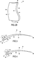
- the length l of the intrados fin 34 measured from the leading edge 18 to the free edge 40, is greater than the length L of the fin extrados 36, measured from the leading edge 18 to the corresponding free edge 42, as illustrated in FIG. figure 3 .
- the length l of the intrados vane 34 can be reduced to become equal to or less than the length L of the upper vane 36 in a second segment S2 of the leading edge shield 32, closer to the head of dawn 26 as dawn foot 28, as illustrated on the figure 4 .
- the mass and especially the inertia of the shield 32 can be reduced without significantly affecting negatively their protection by the same leading edge shield 32.
- the length l of the intrados vane 34 may remain equal to or greater than 70% or even 85% of the length L of the extrados fin 36.
Landscapes
- Engineering & Computer Science (AREA)
- Mechanical Engineering (AREA)
- General Engineering & Computer Science (AREA)
- Chemical & Material Sciences (AREA)
- Materials Engineering (AREA)
- Composite Materials (AREA)
- Architecture (AREA)
- Structures Of Non-Positive Displacement Pumps (AREA)
- Turbine Rotor Nozzle Sealing (AREA)
Description
La présente invention concerne un bouclier de bord d'attaque pour aube de turbomachine. On entend par « turbomachine », dans ce contexte, toute machine dans laquelle peut s'opérer un transfert d'énergie entre un écoulement de fluide et au moins un aubage, comme, par exemple, un compresseur, une pompe, une turbine, une hélice, ou bien une combinaison d'au moins deux de ceux-ci.The present invention relates to a leading edge shield for a turbomachine blade. In this context, the term "turbomachine" means any machine in which energy transfer can take place between a fluid flow and at least one blade, such as, for example, a compressor, a pump, a turbine, a helix, or a combination of at least two thereof.
De tels boucliers de bord d'attaque sont typiquement destinés à protéger les bords d'attaque d'aubes tournantes ou d'aubes directrices contre les impacts. On entend par « aubes », dans ce contexte, tant les aubes de soufflante que les pales d'hélice aérienne. Afin de limiter leur poids, ces aubes sont typiquement principalement formées d'un corps d'aube en composite à matrice organique, par exemple en polymère, renforcée par des fibres. Bien que ces matériaux présentent des qualités mécaniques généralement très favorables, en particulier par rapport à leur masse, ils présentent une certaine sensibilité aux impacts ponctuels. Des boucliers, typiquement en matériau métallique hautement résistant, comme les alliages de titane, sont donc normalement installés sur les bords d'attaque de telles aubes, afin de les protéger contre ces impacts. Ces boucliers prennent normalement la forme d'une fine ailette intrados et une fine ailette extrados jointes par une section plus épaisse chevauchant le bord d'attaque, l'ensemble épousant la forme de l'aube sur le bord d'attaque et des sections adjacentes de l'intrados et de l'extrados, comme par exemple dans les publications de demandes internationales de brevet
La présente divulgation vise à remédier à ces inconvénients, en proposant un bouclier de bord d'attaque pour aube de turbomachine qui permette d'offrir une protection appropriée à l'intrados de cette aube avec une masse et une inertie réduites.The present disclosure aims to remedy these drawbacks by proposing a leading edge shield for a turbomachine blade which makes it possible to offer appropriate protection to the underside of this blade with reduced mass and inertia.
Dans au moins un mode de réalisation, ce but est atteint grâce au fait que, dans ledit bouclier de bord d'attaque, qui peut être en matériau métallique et comporte une ailette intrados et une ailette extrados, s'étendant chacune en hauteur et en longueur et reliées l'une à l'autre sur leur hauteur, l'ailette intrados présente une longueur plus grande que l'ailette extrados sur un premier segment du bouclier de bord d'attaque, mais une longueur égale ou inférieure à l'ailette extrados sur un deuxième segment du bouclier de bord d'attaque.In at least one embodiment, this object is achieved by virtue of the fact that, in said leading edge shield, which may be made of metallic material and includes an extrados wing and an extrados wing, each extending in height and in length and connected to each other on their height, the intrados vane has a greater length than the fin extrados on a first segment of the leading edge shield, but a length equal to or less than the fin extrados on a second segment of the leading edge shield.
Grâce à ces dispositions, il est possible de réduire la masse et l'inertie du bouclier quand le corps d'aube, côté intrados, est moins exposé aux impacts et/ou moins affecté par eux sous ledit deuxième segment du bouclier que sous ledit premier segment.Thanks to these provisions, it is possible to reduce the mass and the inertia of the shield when the blade body, intrados side, is less exposed to the impacts and / or less affected by them under said second segment of the shield that under said first segment.
Ledit premier segment du bouclier peut s'étendre sur au moins 60% de la hauteur des ailettes intrados et extrados. Afin de continuer à assurer une protection suffisante de l'intrados, dans ledit deuxième segment du bouclier la profondeur de l'ailette intrados peut rester égale ou supérieure à 70% de la profondeur de l'ailette extrados, voire 85%.Said first segment of the shield may extend over at least 60% of the height of the intrados and extrados fins. In order to continue to provide sufficient protection of the underside, in said second segment of the shield the depth of the lower wing may remain equal to or greater than 70% of the depth of the extrados fin, or even 85%.
La présente divulgation concerne aussi une aube s'étendant en hauteur d'un pied d'aube à une tête d'aube et comprenant un corps d'aube et un tel bouclier de bord d'attaque assemblé sur le corps d'aube, le corps d'aube étant en matériau composite à matrice en polymère renforcée par des fibres, le bouclier de bord d'attaque étant en un matériau ayant une meilleure résistance aux impacts ponctuels que le matériau composite du corps d'aube, et le premier segment du bouclier de bord d'attaque étant plus proche du pied d'aube que le deuxième segment du bouclier de bord d'attaque.The present disclosure also relates to a blade extending in height from a blade root to a blade head and comprising a blade body and such a leading edge shield assembled on the blade body, blade body being made of a fiber-reinforced polymer matrix composite material, the leading edge shield being made of a material having a better resistance to point impacts than the composite material of the dawn body, and the first segment of the leading edge shield being closer to the blade root than the second segment of the leading edge shield.
La présente divulgation concerne aussi une turbomachine comprenant une pluralité de telles aubes, une soufflante comprenant une pluralité de telles aubes et un turboréacteur à double flux comprenant une telle soufflante.The present disclosure also relates to a turbomachine comprising a plurality of such blades, a fan comprising a plurality of such blades and a turbofan engine comprising such a fan.
L'invention sera bien comprise et ses avantages apparaîtront mieux, à la lecture de la description détaillée qui suit, d'un mode de réalisation représenté à titre d'exemple non limitatif. La description se réfère aux dessins annexés sur lesquels :
- la
figure 1 est une vue schématique en perspective d'un turboréacteur à double flux ; - les
figures 2A et2B sont des vues schématiques en perspective du côté intrados et extrados, respectivement, d'une aube tournante de la soufflante du turboréacteur de lafigure 1 selon un mode de réalisation de l'aube ; et - les
figures 3 et 4 sont des vues partielles en coupe de l'aube desfigures 2A et2B selon les plans III-III et IV-IV, respectivement.
- the
figure 1 is a schematic perspective view of a turbofan engine; - the
Figures 2A and2B are schematic views in perspective of the intrados and extrados side, respectively, of a rotating blade of the turbojet fan of thefigure 1 according to an embodiment of the dawn; and - the
Figures 3 and 4 are partial sectional views of the dawn ofFigures 2A and2B according to plans III-III and IV-IV, respectively.
La
En fonctionnement normal, le vent relatif est sensiblement orienté vers le bord d'attaque 18 de chaque aube 16. Ainsi, ce bord d'attaque 18 est particulièrement exposé aux impacts. En particulier quand l'aube 16 comprend un corps d'aube 30 en matériau composite, notamment à matrice polymère renforcée par des fibres, il convient donc de protéger le bord d'attaque 18 avec un bouclier de bord d'attaque 32 intégré à chaque aube. En d'autres termes, le bouclier de bord d'attaque 32 est assemblé sur le corps d'aube 30.In normal operation, the relative wind is substantially oriented towards the leading
Le bouclier de bord d'attaque 32 est fabriqué en un matériau ayant une meilleure résistante aux impacts ponctuels que le matériau composite du corps d'aube 30. Le bouclier de bord d'attaque 32 est principalement métallique, et plus spécifiquement en alliage à base de titane, comme par exemple le TA6V (Ti-6Al-4V). Le bouclier de bord d'attaque 32 pourrait également être en acier ou en alliage métallique communément désigné par la marque déposée Inconel™. On parle par la suite d'Inconel pour désigner un alliage à base de fer alliés avec du nickel et du chrome.The leading
Le bouclier de bord d'attaque 32 comporte une ailette intrados 34, une ailette extrados 36, qui s'étendent chacune en hauteur sur une hauteur H du bouclier 32 et une section centrale 38 plus épaisse, destinée à chevaucher un bord du corps d'aube 30 et reliant l'ailette intrados 34 et l'ailette extrados 36 sur cette hauteur H. Les ailettes intrados et extrados 34, 36 assurent le positionnement du bouclier 32 sur le corps d'aube 30. Les ailettes intrados et extrados 34, 36 présentent chacune un bord libre 40, 42 et s'étendent chacune en longueur de la section centrale 38 au bord libre 40, 42 correspondant.The leading
Le vent relatif présentant normalement un certain angle d'attaque par rapport au bord d'attaque 18, l'intrados de l'aube 16 est plus exposé aux impacts à proximité du bord d'attaque 18 que l'extrados. Pour cette raison, dans le mode de réalisation illustré, dans un premier segment S1 du bouclier de bord d'attaque 32 adjacent au pied d'aube 28, et s'étendant sur au moins 60 %, voire 75% de la hauteur H du bouclier de bord d'attaque, la longueur l de l'ailette intrados 34, mesurée du bord d'attaque 18 au bord libre 40, est supérieure à la longueur L de l'ailette extrados 36, mesurée du bord d'attaque 18 au bord libre 42 correspondant, comme illustré sur la
Toutefois, grâce vrillage de l'aube et/ou au carter 50, dont l'entrée peut être plus étroite que la soufflante 14, est moins exposée aux impacts à forte énergie. Ainsi, la longueur l de l'ailette intrados 34 peut être réduite pour devenir égale ou inférieure à la longueur L de l'ailette extrados 36 dans un deuxième segment S2 du bouclier de bord d'attaque 32, plus proche de la tête d'aube 26 que du pied d'aube 28, comme illustré sur la
Quoique la présente invention ait été décrite en se référant à un exemple de réalisation spécifique, il est évident que des différentes modifications et changements peuvent être effectués sur ces exemples sans sortir de la portée générale de l'invention telle que définie par les revendications. En outre, des caractéristiques individuelles des différents modes de réalisation évoqués peuvent être combinées dans des modes de réalisation additionnels. Par conséquent, la description et les dessins doivent être considérés dans un sens illustratif plutôt que restrictif.Although the present invention has been described with reference to a specific exemplary embodiment, it is obvious that various modifications and changes can be made to these examples without departing from the general scope of the invention as defined by the claims. In addition, individual features of the various embodiments mentioned can be combined in additional embodiments. Therefore, the description and drawings should be considered in an illustrative rather than restrictive sense.
Claims (10)
- A leading-edge shield (32) for a turbomachine blade (16), said leading-edge shield (32) having a pressure-side wing (34) and a suction-side wing (36), each extending along a height and along a length, the wings being connected together over their height, the pressure-side wing (34) presenting a greater length than the suction-side wing (36) over a first segment (S1) of the leading-edge shield (32), and an equal or smaller length than the suction-side wing (36) over a second segment (S2) of the leading-edge shield (32).
- A leading-edge shield (32) according to claim 1, wherein said first segment (S1) of the shield (32) extends over at least 60% of the height of the pressure-side and suction-side wings (34, 36).
- A leading-edge shield (32) according to either preceding claim, wherein in said second segment (S2) of the shield, the length of the pressure-side wing (34) remains equal to or greater than 70% of the length of the suction-side wing.
- A leading-edge shield (32) according to claim 3, wherein in said second segment (S2) of the shield, the length of the pressure-side wing (34) remains equal to or greater than 85% of the length of the suction-side wing.
- A shield (16) according to any preceding claim, made of metal material.
- A blade (4) extending along a height from a blade root (28) to a blade tip (26) and comprising a blade body (9) and a leading-edge shield (32) according to any preceding claim assembled on the blade body (30), the blade body (9) being made of a composite material having a polymer matrix reinforced by fibers, and the leading-edge shield (32) being made of a material with better point impact resistance than the composite material of the blade body (9).
- A blade (4) according to claim 6, wherein the first segment (S1) of the leading-edge shield (32) is closer to the blade root (28) than is the second segment (S2) of the leading-edge shield (32).
- A turbomachine including a plurality of blades (16) according to claim 6 or claim 7.
- A fan (14) including a plurality of blades (16) according to claim 6 or claim 7.
- A turbofan (10) including a fan (14) according to claim 9.
Applications Claiming Priority (2)
| Application Number | Priority Date | Filing Date | Title |
|---|---|---|---|
| FR1563004A FR3045710B1 (en) | 2015-12-21 | 2015-12-21 | ATTACK SHIELD |
| PCT/FR2016/053603 WO2017109404A1 (en) | 2015-12-21 | 2016-12-21 | Leading edge shield |
Publications (3)
| Publication Number | Publication Date |
|---|---|
| EP3394397A1 EP3394397A1 (en) | 2018-10-31 |
| EP3394397B1 true EP3394397B1 (en) | 2019-10-02 |
| EP3394397B2 EP3394397B2 (en) | 2022-08-10 |
Family
ID=55542877
Family Applications (1)
| Application Number | Title | Priority Date | Filing Date |
|---|---|---|---|
| EP16831497.9A Active EP3394397B2 (en) | 2015-12-21 | 2016-12-21 | Leading edge sheath |
Country Status (9)
| Country | Link |
|---|---|
| US (1) | US10934851B2 (en) |
| EP (1) | EP3394397B2 (en) |
| JP (1) | JP6980661B2 (en) |
| CN (1) | CN108474258B (en) |
| BR (1) | BR112018012740B1 (en) |
| CA (1) | CA3009452A1 (en) |
| FR (1) | FR3045710B1 (en) |
| RU (1) | RU2727825C2 (en) |
| WO (1) | WO2017109404A1 (en) |
Families Citing this family (6)
| Publication number | Priority date | Publication date | Assignee | Title |
|---|---|---|---|---|
| FR3093017B1 (en) * | 2019-02-21 | 2023-02-24 | Safran Aircraft Engines | METHOD FOR REPAIRING A TURBOMACHINE PROPELLER BLADE |
| FR3103855B1 (en) * | 2019-11-29 | 2022-10-21 | Safran | Improved blade leading edge structure. |
| JP7411462B2 (en) * | 2020-03-17 | 2024-01-11 | 三菱重工業株式会社 | Composite wing, rotating machine, and method for forming composite wing |
| FR3121475A1 (en) * | 2021-03-31 | 2022-10-07 | Safran Aircraft Engines | STATOR BLADE FOR A TURBOMACHINE WITH A METAL SHIELD |
| US12577878B2 (en) * | 2024-04-11 | 2026-03-17 | Pratt & Whitney Canada Corp. | Leading edge plating on low pressure compressor vane for weight and strength optimization |
| US12497974B2 (en) * | 2024-05-24 | 2025-12-16 | Rtx Corporation | Cost-effective solid-state deposition of functionally graded titanium hollow fan blade sheath for improved galvanic corrosion resistance |
Citations (5)
| Publication number | Priority date | Publication date | Assignee | Title |
|---|---|---|---|---|
| US4895491A (en) | 1988-06-17 | 1990-01-23 | Environmental Elements Corp. | Fan blade protection system |
| US20090025365A1 (en) | 2007-07-23 | 2009-01-29 | General Electric Company | Airfoil and method for protecting airfoil leading edge |
| US20130004322A1 (en) | 2011-06-28 | 2013-01-03 | United Technologies Corporation | Fan blade with sheath |
| US20130236323A1 (en) | 2012-03-08 | 2013-09-12 | United Technologies Corporation | Leading edge protection and method of making |
| US20150104325A1 (en) | 2012-01-30 | 2015-04-16 | Ihi Corporation | Fan rotor blade of aircraft jet engine |
Family Cites Families (22)
| Publication number | Priority date | Publication date | Assignee | Title |
|---|---|---|---|---|
| JPS5042105U (en) | 1973-08-21 | 1975-04-28 | ||
| US5141400A (en) * | 1991-01-25 | 1992-08-25 | General Electric Company | Wide chord fan blade |
| FR2741590B1 (en) * | 1995-11-29 | 1998-01-30 | Eurocopter France | BLADE WITH REINFORCED PROTECTION AGAINST LIGHTNING, FOR ROTOR OF A GIRAVION |
| JPH11182204A (en) * | 1997-12-15 | 1999-07-06 | Toshiba Corp | Turbine blade |
| FR2867096B1 (en) | 2004-03-08 | 2007-04-20 | Snecma Moteurs | METHOD FOR MANUFACTURING A REINFORCING LEAK OR RELEASING EDGE FOR A BLOWER BLADE |
| US7011502B2 (en) * | 2004-04-15 | 2006-03-14 | General Electric Company | Thermal shield turbine airfoil |
| FR2921099B1 (en) | 2007-09-13 | 2013-12-06 | Snecma | DAMPING DEVICE FOR DRAWINGS OF COMPOSITE MATERIAL |
| EP2072757A1 (en) * | 2007-12-20 | 2009-06-24 | Siemens Aktiengesellschaft | Erosion protection shield for a rotating blade |
| US8814528B2 (en) | 2009-01-22 | 2014-08-26 | Ihi Corporation | Production method of leading edge reinforcement of fan blade |
| US20160052621A1 (en) * | 2009-07-10 | 2016-02-25 | Peter Ireland | Energy efficiency improvements for turbomachinery |
| US20120021243A1 (en) | 2010-07-23 | 2012-01-26 | General Electric Company | Components with bonded edges |
| FR2965202B1 (en) | 2010-09-28 | 2012-10-12 | Snecma | PROCESS FOR MANUFACTURING A PIECE AND COMPOSITE MASSIVE PART OBTAINED BY THIS METHOD |
| FR2970668B1 (en) * | 2011-01-24 | 2013-01-18 | Snecma | PROCESS FOR MAKING A METAL REINFORCEMENT |
| FR2972124B1 (en) | 2011-03-01 | 2014-05-16 | Snecma | METHOD FOR PRODUCING A METAL PIECE SUCH AS A TURBOMACHINE BLADE REINFORCEMENT |
| US9121294B2 (en) * | 2011-12-20 | 2015-09-01 | General Electric Company | Fan blade with composite core and wavy wall trailing edge cladding |
| US9109455B2 (en) * | 2012-01-20 | 2015-08-18 | General Electric Company | Turbomachine blade tip shroud |
| US9404172B2 (en) * | 2012-02-22 | 2016-08-02 | Sikorsky Aircraft Corporation | Erosion and fatigue resistant blade and blade coating |
| EP2867473B1 (en) * | 2012-06-21 | 2020-07-29 | United Technologies Corporation | Blades for an aviation engine and corresponding gas turbine aviation engine |
| US20140219808A1 (en) * | 2012-10-01 | 2014-08-07 | United Technologies Corporation | Sheath with extended wings |
| WO2014149098A2 (en) * | 2013-03-15 | 2014-09-25 | United Technologies Corporation | Hollow fan blade with extended wing sheath |
| US10724379B2 (en) * | 2013-03-15 | 2020-07-28 | Raytheon Technologies Corporation | Locally extended leading edge sheath for fan airfoil |
| US10539025B2 (en) * | 2016-02-10 | 2020-01-21 | General Electric Company | Airfoil assembly with leading edge element |
-
2015
- 2015-12-21 FR FR1563004A patent/FR3045710B1/en active Active
-
2016
- 2016-12-21 EP EP16831497.9A patent/EP3394397B2/en active Active
- 2016-12-21 BR BR112018012740-0A patent/BR112018012740B1/en active IP Right Grant
- 2016-12-21 WO PCT/FR2016/053603 patent/WO2017109404A1/en not_active Ceased
- 2016-12-21 JP JP2018532743A patent/JP6980661B2/en active Active
- 2016-12-21 CN CN201680078441.0A patent/CN108474258B/en active Active
- 2016-12-21 CA CA3009452A patent/CA3009452A1/en active Pending
- 2016-12-21 RU RU2018126685A patent/RU2727825C2/en active
- 2016-12-21 US US16/064,473 patent/US10934851B2/en active Active
Patent Citations (5)
| Publication number | Priority date | Publication date | Assignee | Title |
|---|---|---|---|---|
| US4895491A (en) | 1988-06-17 | 1990-01-23 | Environmental Elements Corp. | Fan blade protection system |
| US20090025365A1 (en) | 2007-07-23 | 2009-01-29 | General Electric Company | Airfoil and method for protecting airfoil leading edge |
| US20130004322A1 (en) | 2011-06-28 | 2013-01-03 | United Technologies Corporation | Fan blade with sheath |
| US20150104325A1 (en) | 2012-01-30 | 2015-04-16 | Ihi Corporation | Fan rotor blade of aircraft jet engine |
| US20130236323A1 (en) | 2012-03-08 | 2013-09-12 | United Technologies Corporation | Leading edge protection and method of making |
Also Published As
| Publication number | Publication date |
|---|---|
| BR112018012740A2 (en) | 2018-12-04 |
| JP6980661B2 (en) | 2021-12-15 |
| BR112018012740B1 (en) | 2022-12-20 |
| RU2727825C2 (en) | 2020-07-24 |
| US10934851B2 (en) | 2021-03-02 |
| RU2018126685A (en) | 2020-01-23 |
| CN108474258A (en) | 2018-08-31 |
| WO2017109404A1 (en) | 2017-06-29 |
| JP2018538481A (en) | 2018-12-27 |
| CN108474258B (en) | 2021-05-28 |
| EP3394397A1 (en) | 2018-10-31 |
| CA3009452A1 (en) | 2017-06-29 |
| FR3045710B1 (en) | 2018-01-26 |
| FR3045710A1 (en) | 2017-06-23 |
| RU2018126685A3 (en) | 2020-05-29 |
| US20190024512A1 (en) | 2019-01-24 |
| EP3394397B2 (en) | 2022-08-10 |
Similar Documents
| Publication | Publication Date | Title |
|---|---|---|
| EP3394396B1 (en) | Leading edge sheath | |
| EP3394397B1 (en) | Leading edge sheath | |
| EP3394399B1 (en) | Blade, associated fan and turbojet engine | |
| EP3394398B1 (en) | Leading edge shield | |
| EP2809883B1 (en) | Jet engine fan blade | |
| EP3332094B1 (en) | Blade comprising a blade body made of composite material and a leading-edge shield | |
| EP3356651B1 (en) | Blade having a shield at the leading edge and method of manufacturing this blade | |
| EP3356650B1 (en) | Blade havind a shield at the leading edge and process of fabricating this blade | |
| EP3473813B1 (en) | Turbine engine with a rectifier unit | |
| FR3121475A1 (en) | STATOR BLADE FOR A TURBOMACHINE WITH A METAL SHIELD | |
| WO2022084615A1 (en) | Fan blade with zero dihedral at the head | |
| EP4226048B1 (en) | Blade made of composite material comprising a leading edge shield, turbine engine comprising the blade | |
| FR3106848A1 (en) | Turbomachinery blade with leading edge shield | |
| CA3009226C (en) | Leading edge shield | |
| FR3112822A1 (en) | BLADE IN COMPOSITE MATERIAL WITH A SHIELD, AND TURBOMACHINE INCLUDING THE BLADE | |
| FR3112821A1 (en) | SHIELD FOR BLADE IN COMPOSITE MATERIAL, BLADE AND TURBOMACHINE COMPRISING THE SHIELD, METHOD FOR MANUFACTURING THE BLADE |
Legal Events
| Date | Code | Title | Description |
|---|---|---|---|
| STAA | Information on the status of an ep patent application or granted ep patent |
Free format text: STATUS: UNKNOWN |
|
| STAA | Information on the status of an ep patent application or granted ep patent |
Free format text: STATUS: THE INTERNATIONAL PUBLICATION HAS BEEN MADE |
|
| PUAI | Public reference made under article 153(3) epc to a published international application that has entered the european phase |
Free format text: ORIGINAL CODE: 0009012 |
|
| STAA | Information on the status of an ep patent application or granted ep patent |
Free format text: STATUS: REQUEST FOR EXAMINATION WAS MADE |
|
| 17P | Request for examination filed |
Effective date: 20180627 |
|
| AK | Designated contracting states |
Kind code of ref document: A1 Designated state(s): AL AT BE BG CH CY CZ DE DK EE ES FI FR GB GR HR HU IE IS IT LI LT LU LV MC MK MT NL NO PL PT RO RS SE SI SK SM TR |
|
| AX | Request for extension of the european patent |
Extension state: BA ME |
|
| DAV | Request for validation of the european patent (deleted) | ||
| DAX | Request for extension of the european patent (deleted) | ||
| GRAP | Despatch of communication of intention to grant a patent |
Free format text: ORIGINAL CODE: EPIDOSNIGR1 |
|
| STAA | Information on the status of an ep patent application or granted ep patent |
Free format text: STATUS: GRANT OF PATENT IS INTENDED |
|
| INTG | Intention to grant announced |
Effective date: 20190613 |
|
| GRAS | Grant fee paid |
Free format text: ORIGINAL CODE: EPIDOSNIGR3 |
|
| GRAA | (expected) grant |
Free format text: ORIGINAL CODE: 0009210 |
|
| STAA | Information on the status of an ep patent application or granted ep patent |
Free format text: STATUS: THE PATENT HAS BEEN GRANTED |
|
| AK | Designated contracting states |
Kind code of ref document: B1 Designated state(s): AL AT BE BG CH CY CZ DE DK EE ES FI FR GB GR HR HU IE IS IT LI LT LU LV MC MK MT NL NO PL PT RO RS SE SI SK SM TR |
|
| REG | Reference to a national code |
Ref country code: GB Ref legal event code: FG4D Free format text: NOT ENGLISH |
|
| REG | Reference to a national code |
Ref country code: CH Ref legal event code: EP Ref country code: AT Ref legal event code: REF Ref document number: 1186379 Country of ref document: AT Kind code of ref document: T Effective date: 20191015 |
|
| REG | Reference to a national code |
Ref country code: DE Ref legal event code: R096 Ref document number: 602016021883 Country of ref document: DE |
|
| REG | Reference to a national code |
Ref country code: IE Ref legal event code: FG4D Free format text: LANGUAGE OF EP DOCUMENT: FRENCH |
|
| REG | Reference to a national code |
Ref country code: SE Ref legal event code: TRGR |
|
| REG | Reference to a national code |
Ref country code: NL Ref legal event code: MP Effective date: 20191002 |
|
| REG | Reference to a national code |
Ref country code: LT Ref legal event code: MG4D |
|
| REG | Reference to a national code |
Ref country code: AT Ref legal event code: MK05 Ref document number: 1186379 Country of ref document: AT Kind code of ref document: T Effective date: 20191002 |
|
| PG25 | Lapsed in a contracting state [announced via postgrant information from national office to epo] |
Ref country code: ES Free format text: LAPSE BECAUSE OF FAILURE TO SUBMIT A TRANSLATION OF THE DESCRIPTION OR TO PAY THE FEE WITHIN THE PRESCRIBED TIME-LIMIT Effective date: 20191002 Ref country code: LV Free format text: LAPSE BECAUSE OF FAILURE TO SUBMIT A TRANSLATION OF THE DESCRIPTION OR TO PAY THE FEE WITHIN THE PRESCRIBED TIME-LIMIT Effective date: 20191002 Ref country code: NL Free format text: LAPSE BECAUSE OF FAILURE TO SUBMIT A TRANSLATION OF THE DESCRIPTION OR TO PAY THE FEE WITHIN THE PRESCRIBED TIME-LIMIT Effective date: 20191002 Ref country code: AT Free format text: LAPSE BECAUSE OF FAILURE TO SUBMIT A TRANSLATION OF THE DESCRIPTION OR TO PAY THE FEE WITHIN THE PRESCRIBED TIME-LIMIT Effective date: 20191002 Ref country code: FI Free format text: LAPSE BECAUSE OF FAILURE TO SUBMIT A TRANSLATION OF THE DESCRIPTION OR TO PAY THE FEE WITHIN THE PRESCRIBED TIME-LIMIT Effective date: 20191002 Ref country code: BG Free format text: LAPSE BECAUSE OF FAILURE TO SUBMIT A TRANSLATION OF THE DESCRIPTION OR TO PAY THE FEE WITHIN THE PRESCRIBED TIME-LIMIT Effective date: 20200102 Ref country code: PT Free format text: LAPSE BECAUSE OF FAILURE TO SUBMIT A TRANSLATION OF THE DESCRIPTION OR TO PAY THE FEE WITHIN THE PRESCRIBED TIME-LIMIT Effective date: 20200203 Ref country code: LT Free format text: LAPSE BECAUSE OF FAILURE TO SUBMIT A TRANSLATION OF THE DESCRIPTION OR TO PAY THE FEE WITHIN THE PRESCRIBED TIME-LIMIT Effective date: 20191002 Ref country code: NO Free format text: LAPSE BECAUSE OF FAILURE TO SUBMIT A TRANSLATION OF THE DESCRIPTION OR TO PAY THE FEE WITHIN THE PRESCRIBED TIME-LIMIT Effective date: 20200102 Ref country code: GR Free format text: LAPSE BECAUSE OF FAILURE TO SUBMIT A TRANSLATION OF THE DESCRIPTION OR TO PAY THE FEE WITHIN THE PRESCRIBED TIME-LIMIT Effective date: 20200103 Ref country code: PL Free format text: LAPSE BECAUSE OF FAILURE TO SUBMIT A TRANSLATION OF THE DESCRIPTION OR TO PAY THE FEE WITHIN THE PRESCRIBED TIME-LIMIT Effective date: 20191002 |
|
| PG25 | Lapsed in a contracting state [announced via postgrant information from national office to epo] |
Ref country code: HR Free format text: LAPSE BECAUSE OF FAILURE TO SUBMIT A TRANSLATION OF THE DESCRIPTION OR TO PAY THE FEE WITHIN THE PRESCRIBED TIME-LIMIT Effective date: 20191002 Ref country code: RS Free format text: LAPSE BECAUSE OF FAILURE TO SUBMIT A TRANSLATION OF THE DESCRIPTION OR TO PAY THE FEE WITHIN THE PRESCRIBED TIME-LIMIT Effective date: 20191002 Ref country code: CZ Free format text: LAPSE BECAUSE OF FAILURE TO SUBMIT A TRANSLATION OF THE DESCRIPTION OR TO PAY THE FEE WITHIN THE PRESCRIBED TIME-LIMIT Effective date: 20191002 Ref country code: IS Free format text: LAPSE BECAUSE OF FAILURE TO SUBMIT A TRANSLATION OF THE DESCRIPTION OR TO PAY THE FEE WITHIN THE PRESCRIBED TIME-LIMIT Effective date: 20200224 |
|
| PG25 | Lapsed in a contracting state [announced via postgrant information from national office to epo] |
Ref country code: AL Free format text: LAPSE BECAUSE OF FAILURE TO SUBMIT A TRANSLATION OF THE DESCRIPTION OR TO PAY THE FEE WITHIN THE PRESCRIBED TIME-LIMIT Effective date: 20191002 |
|
| REG | Reference to a national code |
Ref country code: DE Ref legal event code: R026 Ref document number: 602016021883 Country of ref document: DE |
|
| PLBI | Opposition filed |
Free format text: ORIGINAL CODE: 0009260 |
|
| PLAX | Notice of opposition and request to file observation + time limit sent |
Free format text: ORIGINAL CODE: EPIDOSNOBS2 |
|
| PG2D | Information on lapse in contracting state deleted |
Ref country code: IS |
|
| PG25 | Lapsed in a contracting state [announced via postgrant information from national office to epo] |
Ref country code: RO Free format text: LAPSE BECAUSE OF FAILURE TO SUBMIT A TRANSLATION OF THE DESCRIPTION OR TO PAY THE FEE WITHIN THE PRESCRIBED TIME-LIMIT Effective date: 20191002 Ref country code: EE Free format text: LAPSE BECAUSE OF FAILURE TO SUBMIT A TRANSLATION OF THE DESCRIPTION OR TO PAY THE FEE WITHIN THE PRESCRIBED TIME-LIMIT Effective date: 20191002 Ref country code: DK Free format text: LAPSE BECAUSE OF FAILURE TO SUBMIT A TRANSLATION OF THE DESCRIPTION OR TO PAY THE FEE WITHIN THE PRESCRIBED TIME-LIMIT Effective date: 20191002 Ref country code: IS Free format text: LAPSE BECAUSE OF FAILURE TO SUBMIT A TRANSLATION OF THE DESCRIPTION OR TO PAY THE FEE WITHIN THE PRESCRIBED TIME-LIMIT Effective date: 20200202 |
|
| REG | Reference to a national code |
Ref country code: CH Ref legal event code: PL |
|
| 26 | Opposition filed |
Opponent name: RAYTHEON TECHNOLOGIES CORPORATION Effective date: 20200702 |
|
| REG | Reference to a national code |
Ref country code: BE Ref legal event code: MM Effective date: 20191231 |
|
| PG25 | Lapsed in a contracting state [announced via postgrant information from national office to epo] |
Ref country code: SM Free format text: LAPSE BECAUSE OF FAILURE TO SUBMIT A TRANSLATION OF THE DESCRIPTION OR TO PAY THE FEE WITHIN THE PRESCRIBED TIME-LIMIT Effective date: 20191002 Ref country code: SK Free format text: LAPSE BECAUSE OF FAILURE TO SUBMIT A TRANSLATION OF THE DESCRIPTION OR TO PAY THE FEE WITHIN THE PRESCRIBED TIME-LIMIT Effective date: 20191002 Ref country code: MC Free format text: LAPSE BECAUSE OF FAILURE TO SUBMIT A TRANSLATION OF THE DESCRIPTION OR TO PAY THE FEE WITHIN THE PRESCRIBED TIME-LIMIT Effective date: 20191002 |
|
| PLBB | Reply of patent proprietor to notice(s) of opposition received |
Free format text: ORIGINAL CODE: EPIDOSNOBS3 |
|
| PG25 | Lapsed in a contracting state [announced via postgrant information from national office to epo] |
Ref country code: IE Free format text: LAPSE BECAUSE OF NON-PAYMENT OF DUE FEES Effective date: 20191221 Ref country code: LU Free format text: LAPSE BECAUSE OF NON-PAYMENT OF DUE FEES Effective date: 20191221 |
|
| PG25 | Lapsed in a contracting state [announced via postgrant information from national office to epo] |
Ref country code: SI Free format text: LAPSE BECAUSE OF FAILURE TO SUBMIT A TRANSLATION OF THE DESCRIPTION OR TO PAY THE FEE WITHIN THE PRESCRIBED TIME-LIMIT Effective date: 20191002 Ref country code: CH Free format text: LAPSE BECAUSE OF NON-PAYMENT OF DUE FEES Effective date: 20191231 Ref country code: BE Free format text: LAPSE BECAUSE OF NON-PAYMENT OF DUE FEES Effective date: 20191231 Ref country code: LI Free format text: LAPSE BECAUSE OF NON-PAYMENT OF DUE FEES Effective date: 20191231 |
|
| PG25 | Lapsed in a contracting state [announced via postgrant information from national office to epo] |
Ref country code: CY Free format text: LAPSE BECAUSE OF FAILURE TO SUBMIT A TRANSLATION OF THE DESCRIPTION OR TO PAY THE FEE WITHIN THE PRESCRIBED TIME-LIMIT Effective date: 20191002 |
|
| PG25 | Lapsed in a contracting state [announced via postgrant information from national office to epo] |
Ref country code: MT Free format text: LAPSE BECAUSE OF FAILURE TO SUBMIT A TRANSLATION OF THE DESCRIPTION OR TO PAY THE FEE WITHIN THE PRESCRIBED TIME-LIMIT Effective date: 20191002 Ref country code: HU Free format text: LAPSE BECAUSE OF FAILURE TO SUBMIT A TRANSLATION OF THE DESCRIPTION OR TO PAY THE FEE WITHIN THE PRESCRIBED TIME-LIMIT; INVALID AB INITIO Effective date: 20161221 |
|
| PG25 | Lapsed in a contracting state [announced via postgrant information from national office to epo] |
Ref country code: TR Free format text: LAPSE BECAUSE OF FAILURE TO SUBMIT A TRANSLATION OF THE DESCRIPTION OR TO PAY THE FEE WITHIN THE PRESCRIBED TIME-LIMIT Effective date: 20191002 |
|
| PG25 | Lapsed in a contracting state [announced via postgrant information from national office to epo] |
Ref country code: MK Free format text: LAPSE BECAUSE OF FAILURE TO SUBMIT A TRANSLATION OF THE DESCRIPTION OR TO PAY THE FEE WITHIN THE PRESCRIBED TIME-LIMIT Effective date: 20191002 |
|
| PUAH | Patent maintained in amended form |
Free format text: ORIGINAL CODE: 0009272 |
|
| STAA | Information on the status of an ep patent application or granted ep patent |
Free format text: STATUS: PATENT MAINTAINED AS AMENDED |
|
| 27A | Patent maintained in amended form |
Effective date: 20220810 |
|
| AK | Designated contracting states |
Kind code of ref document: B2 Designated state(s): AL AT BE BG CH CY CZ DE DK EE ES FI FR GB GR HR HU IE IS IT LI LT LU LV MC MK MT NL NO PL PT RO RS SE SI SK SM TR |
|
| REG | Reference to a national code |
Ref country code: DE Ref legal event code: R102 Ref document number: 602016021883 Country of ref document: DE |
|
| REG | Reference to a national code |
Ref country code: SE Ref legal event code: RPEO |
|
| PGFP | Annual fee paid to national office [announced via postgrant information from national office to epo] |
Ref country code: DE Payment date: 20241121 Year of fee payment: 9 |
|
| PGFP | Annual fee paid to national office [announced via postgrant information from national office to epo] |
Ref country code: IT Payment date: 20241121 Year of fee payment: 9 |
|
| PGFP | Annual fee paid to national office [announced via postgrant information from national office to epo] |
Ref country code: GB Payment date: 20251229 Year of fee payment: 10 |
|
| PGFP | Annual fee paid to national office [announced via postgrant information from national office to epo] |
Ref country code: FR Payment date: 20251222 Year of fee payment: 10 |
|
| PGFP | Annual fee paid to national office [announced via postgrant information from national office to epo] |
Ref country code: SE Payment date: 20251217 Year of fee payment: 10 |