EP3394366B1 - Steering system for pool cleaners - Google Patents
Steering system for pool cleaners Download PDFInfo
- Publication number
- EP3394366B1 EP3394366B1 EP16871593.6A EP16871593A EP3394366B1 EP 3394366 B1 EP3394366 B1 EP 3394366B1 EP 16871593 A EP16871593 A EP 16871593A EP 3394366 B1 EP3394366 B1 EP 3394366B1
- Authority
- EP
- European Patent Office
- Prior art keywords
- assembly
- pool cleaner
- gear
- steering device
- program
- Prior art date
- Legal status (The legal status is an assumption and is not a legal conclusion. Google has not performed a legal analysis and makes no representation as to the accuracy of the status listed.)
- Active
Links
Images


Classifications
-
- E—FIXED CONSTRUCTIONS
- E04—BUILDING
- E04H—BUILDINGS OR LIKE STRUCTURES FOR PARTICULAR PURPOSES; SWIMMING OR SPLASH BATHS OR POOLS; MASTS; FENCING; TENTS OR CANOPIES, IN GENERAL
- E04H4/00—Swimming or splash baths or pools
- E04H4/14—Parts, details or accessories not otherwise provided for
- E04H4/16—Parts, details or accessories not otherwise provided for specially adapted for cleaning
- E04H4/1654—Self-propelled cleaners
- E04H4/1672—Connections to the pool water circulation system
-
- E—FIXED CONSTRUCTIONS
- E04—BUILDING
- E04H—BUILDINGS OR LIKE STRUCTURES FOR PARTICULAR PURPOSES; SWIMMING OR SPLASH BATHS OR POOLS; MASTS; FENCING; TENTS OR CANOPIES, IN GENERAL
- E04H4/00—Swimming or splash baths or pools
- E04H4/14—Parts, details or accessories not otherwise provided for
- E04H4/16—Parts, details or accessories not otherwise provided for specially adapted for cleaning
- E04H4/1654—Self-propelled cleaners
- E04H4/1663—Self-propelled cleaners the propulsion resulting from an intermittent interruption of the waterflow through the cleaner
Definitions
- the present invention relates to a steering mechanism, and more particularly, to a steering mechanism for a pool cleaner.
- Automated pool cleaners without an active steering mechanism tend to repeat the same pattern of motion throughout the pool environment. For this reason it can be difficult for an automated cleaning device to adequately clean the entire floor of a pool. Moreover, such pool cleaners are often more prone to become stuck in a difficult area of the pool.
- Some methods have been developed to overcome these problems.
- a return water flow jet for example, can be adjusted to influence the connecting hose of a pool cleaner.
- Another approach is to employ a rotating connecting hose.
- US2008/092322 discloses an apparatus for inducing variable randomized patterns of traversing at least a floor of a swimming pool by a suction cleaner device; said apparatus including a water flow driven mechanism interposed between a suction pump inlet in a wall of said swimming pool and said suction cleaning device; said apparatus further including a suction hose and an angled connector attached to said suction hose; said angled connector rotatably connected to a swivelling outlet port of said suction cleaning device; said apparatus inducing substantially continuous axial rotation of said suction hose and said angled connector whereby rotating the hose and angled connector alters the geometry of the propulsion force of the pool cleaner thus steering the pool cleaner all over the pool.
- WO2004/097145 discloses a device for promoting free movement of a hose of an automatic swimming pool cleaner, prevents it from becoming stuck by constantly twisting at least one portion of the pool hose to which it is attached.
- the device comprises a coupling for two lengths of a pool hose and has an inlet and an outlet for the flow of water therethrough.
- a paddle wheel is located in a passage between the inlet and outlet, flow of water therethrough causing rotation of the paddle wheel.
- a series of gears transmits the rotation to a pin indexer which causes incremental rotation of an outer drive gear associated with the inlet connector, effecting rotation thereof.
- a pool cleaner assembly 10 includes a pool cleaner 12 and a steering device 14.
- the steering device 14 has rotatably connected first and second steering device ends 18, 20 arranged between the pool cleaner body 12 and a water hose 22.
- the steering device 14 is operable to use water flow passing therethrough to generate relative rotational motion between the first and second steering device ends.
- the pool cleaner 12 includes a body 24 supported for motion over an underwater pool surface.
- the pool cleaner body 24 defines a water source connection 26 and, on a lower surface thereof, a suction opening 28 through which debris, entrained in water, is removed from the underwater pool surface.
- the water source connection 26 is connected directly to the second steering device end 20.
- the steering device could be affixed to the pool cleaner body prior to sale (e.g., during manufacturing), or configured for connection to the water source connection of a pre-existing pool cleaner body.
- the steering device could be connected indirectly to the water source connection; for example, via an additional length of water hose.
- any swivel functionality built thereinto is preferably disabled, such that the steering effect of the steering device is not undesirably counteracted.
- the steering device could be connected indirectly to the water source connection; for example, via an additional length of water hose.
- water-driven pool cleaners are of two types: suction-driven cleaners and pressure-driven cleaners.
- the water hose is connected to a water return connection of the pool circulation system and the water drawn in via the suction opening passes through the hose to the water return.
- the water hose is connected to a water supply connection of the pool circulation system and water is drawn into the suction opening via suction forces typically induced via a venturi effect using the water flowing into the pool cleaner body from the water hose.
- the depicted pool cleaner 12 is a suction-driven cleaner, and more specifically, a suction-driven cleaner of the type supported for movement by a flexible disc 32, where intermittent interruption of suction flow via an internal diaphragm results in movement over pool surfaces.
- the present invention is not necessarily limited to use in connection with such a cleaner and could readily be applied with equivalent effect to other types of suction-driven cleaners, as well as to pressure-driven cleaners. Additionally, elements used in the gearing of the depicted steering device 14 could be employed in internal steering mechanisms for pool cleaners and other devices, whether driven by water or other forces.
- the steering device 14 includes a body 34, advantageously formed of first and second body sections 38, 40 to facilitate assembly.
- the first steering device end 18 is rotatably mounted within the body 34, extending through an opening 42 in the first body section 38, while the second steering device end 20 is fixed to the second body section 40. It will be appreciated that fixed and rotatable ends could be reversed or both ends could be rotatable relative to the steering device body.
- a fluid passage 44 is defined in the body 34 extending between the first and second ends 18 and 20, allowing water to pass through the steering device 14 from the pool cleaner 12 to the water hose 22 (or vice versa).
- An internal opening 46 is defined in the fluid passage 44 within the body 34 allowing another flow path for water therethrough for driving a driving unit 50.
- the driving unit 50 includes a shaft mounted water wheel 52, which generates rotational motion from the water flow through the steering device 14, in turn driving a timing assembly 54 and a program gear assembly 56.
- the timing assembly 54 includes a plurality of gears 60 which reduce (or increase) the rotational speed generated by the drive unit to the rotational speed input to the program gear assembly 56.
- the program gear assembly 56 includes a program gear 62, driven by the drive unit 50 via the timing assembly, and an output gear assembly 64, which imparts rotational motion to the first steering device end 18.
- the output gear assembly 64 drives the first steering device end 18 via a steering gear 66 formed therearound and rotatable therewith.
- the program gear 62 includes a plurality of inwardly oriented teeth 70 and a plurality of outwardly oriented teeth 72.
- the inwardly oriented teeth 70 are arranged around a portion of an outer periphery 74, while the outwardly oriented teeth 72 are arranged around a portion of an inner periphery or hub 76.
- This arrangement permits a single output gear 80 to be used, positioned between the outer and inner peripheries 74, 76.
- the output gear 80 (best seen in Figure 5 ) is a compound gear with first and second axially separated sets of teeth, 82, 84, with the first set 82 engaging the program gear 62 and the second set 84 engaging the steering gear 66.
- the program gear 62 is rotationally driven by the drive unit 50 (see Figure 2 ) in a constant rotational direction (indicated by arrow 90).
- the output gear 80 engages the inwardly oriented teeth 70, and consequently is driven in a rotational direction (arrow 92A) matching the program gear 62, in turn driving the steering gear 66 (and first steering device end 18) in a rotational direction counter (arrow 94A) to the program gear 62.
- a period can be set where the output gear 80 is not driven by either set of program gear teeth 70, 72, and thus the output gear 80 and steering gear 66 are free to rotate in any direction (as represented by arrows 92C, 94C).
- the first and second steering device ends 18, 20 are free to rotate (or not rotate) relative to one another in a "neutral" phase of the steering device 14.
- the arc length of rotation in each direction, as well as of any neutral phases, can be varied by varying the angular extends covered by the inwardly and outwardly oriented teeth 70, 72.
- the inwardly and outwardly oriented teeth 70, 72 are each grouped into a single segment with two neutral phases therebetween.
- the inwardly and outwardly oriented teeth could each be arranged in multiple separate segments.
- the rotational speed in the different rotational directions is advantageously also varied.
- differing tooth counts and positions between the inwardly and outwardly oriented teeth 70, 72 result in a significantly different rotational and counter-rotational speeds of the output gear 80 and the steering gear 66.
- Changing rotational speed as well as direction can further enhance the steering effect of the steering device 14, as well as assist in helping the pool cleaner 12 disengage itself from obstacles.
- the rotational durations and speeds are preferably selected such that the pool cleaner 12 will rotate through 360 degrees after multiple complete turns of the program gear 62.
- the steering device body 34 advantageously also includes a mounting frame 100 sandwiched between the first and second body sections 38, 40.
- the mounting frame 100 supports the program gear assembly 56 and first end 18 above the drive unit 50 and second body section 40.
- An angled neck 102 advantageously connects the body 34 to the pool cleaner body 24, which allows the hose 22 to connect vertically to the first end 18, and perpendicularly to the surface underlying the pool cleaner 12.
- Other orientations could be used, but with the depicted pool cleaner 12, this orientation helps prevent the action of the steering device 14 from causing an undesirable break in traction between the pool cleaner 12 and the underlying pool surface.
- FIG. 7 illustrates a method for steering a pool cleaner using a steering device 14.
- the steering device 14 is connected between a water hose and a water source connection 14 of the pool cleaner 12.
- water flow is initiated through the steering device 14, water hose and pool cleaner 12.
- the water flow through the steering device 14 is used to generate relative rotational motion between first and second steering device ends 18 and 20 connected to the water hose and the water source connection of the pool cleaner, respectively.
- the water flow can move from the pool cleaner 12 to the water source or from the water source to the pool cleaner 12, depending the type of pool cleaner (e.g., suction driven, pressure driven).
Description
- The present invention relates to a steering mechanism, and more particularly, to a steering mechanism for a pool cleaner.
- Automated pool cleaners without an active steering mechanism tend to repeat the same pattern of motion throughout the pool environment. For this reason it can be difficult for an automated cleaning device to adequately clean the entire floor of a pool. Moreover, such pool cleaners are often more prone to become stuck in a difficult area of the pool. Some methods have been developed to overcome these problems. A return water flow jet, for example, can be adjusted to influence the connecting hose of a pool cleaner. Another approach is to employ a rotating connecting hose.
-
US2008/092322 discloses an apparatus for inducing variable randomized patterns of traversing at least a floor of a swimming pool by a suction cleaner device; said apparatus including a water flow driven mechanism interposed between a suction pump inlet in a wall of said swimming pool and said suction cleaning device; said apparatus further including a suction hose and an angled connector attached to said suction hose; said angled connector rotatably connected to a swivelling outlet port of said suction cleaning device; said apparatus inducing substantially continuous axial rotation of said suction hose and said angled connector whereby rotating the hose and angled connector alters the geometry of the propulsion force of the pool cleaner thus steering the pool cleaner all over the pool. - Further,
WO2004/097145 discloses a device for promoting free movement of a hose of an automatic swimming pool cleaner, prevents it from becoming stuck by constantly twisting at least one portion of the pool hose to which it is attached. The device comprises a coupling for two lengths of a pool hose and has an inlet and an outlet for the flow of water therethrough. A paddle wheel is located in a passage between the inlet and outlet, flow of water therethrough causing rotation of the paddle wheel. A series of gears transmits the rotation to a pin indexer which causes incremental rotation of an outer drive gear associated with the inlet connector, effecting rotation thereof. - These methods have, however, been found to be of rather limited value. A more effective steering mechanism for pool cleaners to improve cleaning coverage and efficiency is therefore desirable.
- According to the present invention, there is provided a pool cleaner assembly as set forth in Claim 1 of the appended claims. Further features of the invention are set forth in
Claims 2 to 11 of the appended claims. - The invention will now be described further, by way of example, with reference to the accompanying drawings, in which:
-
Figure 1 is a perspective view of a pool cleaner assembly including a steering device attached to a pool cleaner, according to an embodiment of the invention; -
Figure 2 is an exploded perspective view of the steering device ofFigure 1 ; -
Figure 3 is a perspective view of the steering device ofFigure 1 , with a section removed to show details; -
Figure 4 is a detail view of area 4 ofFigure 3 ; -
Figure 5 is a perspective view of an output gear of the steering device ofFigure 1 ; -
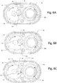
Figures 6A-6C are plan views of different operational states of the steering device of claim 1 ; and -
Figure 7 is a flow diagram of a method of steering a pool cleaner, according to a method aspect of the present invention. - Referring to
Figure 1 , according to an embodiment of the present invention, apool cleaner assembly 10 includes apool cleaner 12 and asteering device 14. Thesteering device 14 has rotatably connected first and second steering device ends 18, 20 arranged between thepool cleaner body 12 and awater hose 22. Thesteering device 14 is operable to use water flow passing therethrough to generate relative rotational motion between the first and second steering device ends. - The
pool cleaner 12 includes abody 24 supported for motion over an underwater pool surface. Thepool cleaner body 24 defines awater source connection 26 and, on a lower surface thereof, a suction opening 28 through which debris, entrained in water, is removed from the underwater pool surface. In the depicted embodiment, thewater source connection 26 is connected directly to the secondsteering device end 20. Notably, the steering device could be affixed to the pool cleaner body prior to sale (e.g., during manufacturing), or configured for connection to the water source connection of a pre-existing pool cleaner body. Additionally, the steering device could be connected indirectly to the water source connection; for example, via an additional length of water hose. When used with an existing cleaner, any swivel functionality built thereinto is preferably disabled, such that the steering effect of the steering device is not undesirably counteracted. Additionally, the steering device could be connected indirectly to the water source connection; for example, via an additional length of water hose. - Generally, water-driven pool cleaners are of two types: suction-driven cleaners and pressure-driven cleaners. In the former, the water hose is connected to a water return connection of the pool circulation system and the water drawn in via the suction opening passes through the hose to the water return. In the latter, the water hose is connected to a water supply connection of the pool circulation system and water is drawn into the suction opening via suction forces typically induced via a venturi effect using the water flowing into the pool cleaner body from the water hose. The depicted
pool cleaner 12 is a suction-driven cleaner, and more specifically, a suction-driven cleaner of the type supported for movement by aflexible disc 32, where intermittent interruption of suction flow via an internal diaphragm results in movement over pool surfaces. However, the present invention is not necessarily limited to use in connection with such a cleaner and could readily be applied with equivalent effect to other types of suction-driven cleaners, as well as to pressure-driven cleaners. Additionally, elements used in the gearing of the depictedsteering device 14 could be employed in internal steering mechanisms for pool cleaners and other devices, whether driven by water or other forces. - Referring also to
Figure 2 , thesteering device 14 includes abody 34, advantageously formed of first andsecond body sections steering device end 18 is rotatably mounted within thebody 34, extending through anopening 42 in thefirst body section 38, while the secondsteering device end 20 is fixed to thesecond body section 40. It will be appreciated that fixed and rotatable ends could be reversed or both ends could be rotatable relative to the steering device body. - A
fluid passage 44 is defined in thebody 34 extending between the first andsecond ends steering device 14 from thepool cleaner 12 to the water hose 22 (or vice versa). Aninternal opening 46 is defined in thefluid passage 44 within thebody 34 allowing another flow path for water therethrough for driving adriving unit 50. - The
driving unit 50 includes a shaft mounted water wheel 52, which generates rotational motion from the water flow through thesteering device 14, in turn driving atiming assembly 54 and aprogram gear assembly 56. Thetiming assembly 54 includes a plurality ofgears 60 which reduce (or increase) the rotational speed generated by the drive unit to the rotational speed input to theprogram gear assembly 56. - Referring also to
Figures 3 and 4 , theprogram gear assembly 56 includes aprogram gear 62, driven by thedrive unit 50 via the timing assembly, and anoutput gear assembly 64, which imparts rotational motion to the firststeering device end 18. In the depicted embodiment, theoutput gear assembly 64 drives the firststeering device end 18 via asteering gear 66 formed therearound and rotatable therewith. - The
program gear 62 includes a plurality of inwardlyoriented teeth 70 and a plurality of outwardlyoriented teeth 72. The inwardlyoriented teeth 70 are arranged around a portion of anouter periphery 74, while the outwardlyoriented teeth 72 are arranged around a portion of an inner periphery orhub 76. This arrangement permits asingle output gear 80 to be used, positioned between the outer andinner peripheries Figure 5 ) is a compound gear with first and second axially separated sets of teeth, 82, 84, with thefirst set 82 engaging theprogram gear 62 and thesecond set 84 engaging thesteering gear 66. - Referring to
Figures 6A-6C , theprogram gear 62 is rotationally driven by the drive unit 50 (seeFigure 2 ) in a constant rotational direction (indicated by arrow 90). During a first portion ofprogram gear 62 rotation (as inFigure 6A ), theoutput gear 80 engages the inwardlyoriented teeth 70, and consequently is driven in a rotational direction (arrow 92A) matching theprogram gear 62, in turn driving the steering gear 66 (and first steering device end 18) in a rotational direction counter (arrow 94A) to theprogram gear 62. - During a second portion of
program gear 62 rotation (as inFigure 6B ), theoutput gear 80 engages the outwardlyoriented teeth 72, and is driven in a rotational direction (arrow 92B) counter to theprogram gear 62, in turn driving thesteering gear 66 in a rotational direction (arrow 94B) the same as theprogram gear 62. Thus, as theprogram gear 62 rotates, the direction of relative rotation between the first and second steering device ends 18, 20 is automatically changed. - As seen in
Figure 6C , during a third portion of program gear rotation 62 (occurring between first and second portions), a period can be set where theoutput gear 80 is not driven by either set ofprogram gear teeth output gear 80 andsteering gear 66 are free to rotate in any direction (as represented byarrows steering device 14. - The arc length of rotation in each direction, as well as of any neutral phases, can be varied by varying the angular extends covered by the inwardly and outwardly
oriented teeth teeth - The rotational speed in the different rotational directions is advantageously also varied. In the depicted embodiment, differing tooth counts and positions between the inwardly and outwardly oriented
teeth output gear 80 and thesteering gear 66. Changing rotational speed as well as direction can further enhance the steering effect of thesteering device 14, as well as assist in helping thepool cleaner 12 disengage itself from obstacles. Generally, the rotational durations and speeds are preferably selected such that thepool cleaner 12 will rotate through 360 degrees after multiple complete turns of theprogram gear 62. - The
steering device body 34 advantageously also includes a mountingframe 100 sandwiched between the first andsecond body sections frame 100 supports theprogram gear assembly 56 andfirst end 18 above thedrive unit 50 andsecond body section 40. Anangled neck 102 advantageously connects thebody 34 to the poolcleaner body 24, which allows thehose 22 to connect vertically to thefirst end 18, and perpendicularly to the surface underlying thepool cleaner 12. Other orientations could be used, but with the depictedpool cleaner 12, this orientation helps prevent the action of thesteering device 14 from causing an undesirable break in traction between thepool cleaner 12 and the underlying pool surface. -
FIG. 7 illustrates a method for steering a pool cleaner using asteering device 14. Atstep 702, thesteering device 14 is connected between a water hose and awater source connection 14 of thepool cleaner 12. Atstep 704, water flow is initiated through thesteering device 14, water hose andpool cleaner 12. Atstep 706, the water flow through thesteering device 14 is used to generate relative rotational motion between first and second steering device ends 18 and 20 connected to the water hose and the water source connection of the pool cleaner, respectively. The water flow can move from thepool cleaner 12 to the water source or from the water source to thepool cleaner 12, depending the type of pool cleaner (e.g., suction driven, pressure driven). - In general, the foregoing description is provided for exemplary and illustrative purposes; the present invention is not necessarily limited thereto. Rather, those skilled in the art will appreciate that additional modifications, as well as adaptations for particular circumstances, will fall within the scope of the invention as set forth in the appended claims.
Claims (11)
- A pool cleaner assembly (10) comprising a pool cleaner body (24) supported for motion over an underwater pool surface, the pool cleaner body (24) defining a water source connection (26) and a suction opening (28) on a lower surface thereof through which debris is removed from the underwater pool surface; and
a steering device (14) having a first steering device end (18) configured for connection to a water hose (22) and a second steering device end (20) connected to the water source connection (26) of the pool cleaner body (24), the steering device being operable to generate relative rotational motion between the first (18) and second (20) steering device ends, a steering gear (66) being fixedly coupled to one of the first and second steering device ends;
wherein the steering device (14) includes:a steering device body (34);a driving unit (50) configured to convert water flow through the steering device body to rotational motion; anda program gear (56) assembly driven by the driving unit (50) and generating the relative rotational motion between the first and second steering device ends (18,20);wherein the program gear (56) is configured to automatically alternate the relative rotational motion between the first and second steering device ends (18,20) between a first rotational direction and a second rotational direction counter to the first rotational direction; andwherein the program gear assembly includes:a program gear (62) having a plurality of inwardly oriented teeth (70) and plurality of outwardly oriented teeth (72); andan output gear assembly (64) including at least one output gear (80), the output gear assembly arranged adjacent to the program gear (62) such that during a first portion of program gear rotation, the output gear assembly is driven by the inwardly oriented teeth in the first rotational direction, and during a second portion of program gear rotation, the output gear assembly is driven by the outwardly oriented teeth in the second rotational direction, the output gear (64) being engaged with the steering gear (66). - The pool cleaner assembly of claim 1, further comprising a water hose (22) connected to the second steering device end.
- The pool cleaner assembly of any preceding claim, wherein the inwardly oriented teeth extend inwardly from an outer periphery of the program gear, and the outwardly oriented teeth extend outwardly from an inner periphery of the program gear, the at least one output gear being arranged between the outer and inner peripheries so as to engage the inwardly oriented teeth during the first portion of program gear rotation, and to engage the outwardly oriented teeth during the second portion of the program gear rotation.
- The pool cleaner assembly of any preceding claim, wherein the at least one output gear (80) is a compound gear including first and second axially separated sets of teeth, the first set of teeth engaging the program gear, the second set of teeth engaging the steering gear.
- The pool cleaner assembly of any preceding claim, wherein, during a third portion of program gear rotation, the output gear assembly is not driven by either inwardly oriented teeth or the outwardly oriented teeth.
- The pool cleaner assembly of claim 5, wherein the first and second steering device ends are freely rotatable relative to one another during the third portion of program gear rotation.
- The pool cleaner assembly of any preceding claim, wherein the program gear assembly is configured such that rotational speeds in the first and second rotational directions are different.
- The pool cleaner assembly of any preceding claim, wherein a timing assembly (54) is arranged between the driving unit and the program gear assembly, the timing assembly being configured to convert a first rotational speed of the driving unit to a second rotational speed of the program gear assembly.
- The pool cleaner assembly of any preceding claim, wherein the pool cleaner body is configured such that water introduced through the suction opening is discharged via the water source connection.
- The pool cleaner assembly of any preceding claim, further comprising a flexible disc (32) arranged around the suction opening and supporting the pool cleaner body for motion over the underwater pool surface.
- The pool cleaner assembly of claim 1, wherein the steering device is connected directly to the water source connection (26) of the pool cleaner body (24).
Applications Claiming Priority (2)
| Application Number | Priority Date | Filing Date | Title |
|---|---|---|---|
| US201562261895P | 2015-12-02 | 2015-12-02 | |
| PCT/US2016/064665 WO2017096194A1 (en) | 2015-12-02 | 2016-12-02 | Steering system for pool cleaners |
Publications (3)
| Publication Number | Publication Date |
|---|---|
| EP3394366A1 EP3394366A1 (en) | 2018-10-31 |
| EP3394366A4 EP3394366A4 (en) | 2019-08-14 |
| EP3394366B1 true EP3394366B1 (en) | 2020-10-14 |
Family
ID=58797906
Family Applications (1)
| Application Number | Title | Priority Date | Filing Date |
|---|---|---|---|
| EP16871593.6A Active EP3394366B1 (en) | 2015-12-02 | 2016-12-02 | Steering system for pool cleaners |
Country Status (4)
| Country | Link |
|---|---|
| US (2) | US10513864B2 (en) |
| EP (1) | EP3394366B1 (en) |
| AU (1) | AU2016362492A1 (en) |
| WO (1) | WO2017096194A1 (en) |
Families Citing this family (4)
| Publication number | Priority date | Publication date | Assignee | Title |
|---|---|---|---|---|
| USD854267S1 (en) * | 2017-07-18 | 2019-07-16 | Nc Brands L.P. | Pool cleaner body |
| WO2019035873A1 (en) * | 2017-08-15 | 2019-02-21 | Nc Brands, L.P. | Pool cleaner with diaphragm cassette unit and retention mechanism |
| CN107762195B (en) * | 2017-11-20 | 2023-09-19 | 明达实业(厦门)有限公司 | Driving reversing mechanism and pool cleaner |
| CN112412128B (en) * | 2019-08-21 | 2022-02-15 | 宁波市普世达泳池用品有限公司 | Pool water energy cleaner |
Family Cites Families (11)
| Publication number | Priority date | Publication date | Assignee | Title |
|---|---|---|---|---|
| US2144160A (en) * | 1931-07-02 | 1939-01-17 | Chrysler Corp | Automobile clutch mechanism |
| AU552555B2 (en) * | 1982-06-16 | 1986-06-05 | Jack Nel Agencies (Panama) S.A. | Suction cleaner for submerged surfaces |
| GB2322539B (en) * | 1997-02-26 | 2000-06-28 | Michael Chandler | Pool cleaning apparatus |
| WO1998051888A1 (en) * | 1997-05-13 | 1998-11-19 | Baracuda International Corporation | Hose rotator for automatic pool cleaner |
| US6158464A (en) * | 1998-11-23 | 2000-12-12 | Letro Products, Inc. | Low pressure back-up valve for pool cleaner |
| AU2003223794B2 (en) * | 2002-03-15 | 2008-05-08 | Johannes Stephanus Grobler | Guiding apparatus for operating a pool cleaner |
| DE10253254B3 (en) * | 2002-11-15 | 2004-05-27 | Sgl Carbon Ag | Electrode connection with coated contact surfaces |
| WO2004097145A1 (en) | 2003-04-29 | 2004-11-11 | David Alan Bray | Adjunct for a swimming pool cleaner |
| SE530209C2 (en) * | 2005-01-07 | 2008-04-01 | Htc Sweden Ab | Processing plate with processing elements with separate lining |
| WO2007141739A2 (en) * | 2006-06-06 | 2007-12-13 | Albertus Wilhelmus Smook | Pool cleaner accessory |
| US20080092322A1 (en) | 2006-10-18 | 2008-04-24 | Roy Michael Halle | Pool cleaning device |
-
2016
- 2016-12-02 WO PCT/US2016/064665 patent/WO2017096194A1/en active Application Filing
- 2016-12-02 US US15/367,853 patent/US10513864B2/en active Active
- 2016-12-02 AU AU2016362492A patent/AU2016362492A1/en not_active Abandoned
- 2016-12-02 EP EP16871593.6A patent/EP3394366B1/en active Active
-
2019
- 2019-04-18 US US16/387,947 patent/US20190242146A1/en not_active Abandoned
Non-Patent Citations (1)
| Title |
|---|
| None * |
Also Published As
| Publication number | Publication date |
|---|---|
| US20190242146A1 (en) | 2019-08-08 |
| AU2016362492A1 (en) | 2018-06-07 |
| WO2017096194A1 (en) | 2017-06-08 |
| US20170159311A1 (en) | 2017-06-08 |
| EP3394366A1 (en) | 2018-10-31 |
| US10513864B2 (en) | 2019-12-24 |
| EP3394366A4 (en) | 2019-08-14 |
Similar Documents
| Publication | Publication Date | Title |
|---|---|---|
| EP3394366B1 (en) | Steering system for pool cleaners | |
| US6782578B1 (en) | Swimming pool pressure cleaner with internal steering mechanism | |
| US9677295B2 (en) | Scrubber assembly for a pool cleaner | |
| AU2011279710B2 (en) | Automatic pool cleaners and components thereof | |
| CN105007843B (en) | Medical pump | |
| US8505143B2 (en) | Programmable steerable robot particularly useful for cleaning swimming pools | |
| US20210404203A1 (en) | Pool Cleaner with Hydraulic Timer Assembly | |
| US20130081986A1 (en) | Pool Cleaner with Multi-Stage Venturi Vacuum Assembly | |
| WO2024046444A1 (en) | Transmission mechanism and underwater cleaning robot | |
| AU2000253018B2 (en) | Swimming pool pressure cleaner with internal steering mechanism | |
| AU2005239660B2 (en) | Power Steering Adaptor for Suction Pool Cleaner | |
| EP3212860A1 (en) | Pool cleaner drive mechanism | |
| CN112696561A (en) | Pipeline robot | |
| ZA200302320B (en) | Swimming pool pressure cleaner with internal steering mechanism. | |
| JP2008054717A (en) | Suction head and vacuum cleaner using the same | |
| AU2006214794A1 (en) | Steering adaptor for suction pool cleaner |
Legal Events
| Date | Code | Title | Description |
|---|---|---|---|
| STAA | Information on the status of an ep patent application or granted ep patent |
Free format text: STATUS: THE INTERNATIONAL PUBLICATION HAS BEEN MADE |
|
| PUAI | Public reference made under article 153(3) epc to a published international application that has entered the european phase |
Free format text: ORIGINAL CODE: 0009012 |
|
| STAA | Information on the status of an ep patent application or granted ep patent |
Free format text: STATUS: REQUEST FOR EXAMINATION WAS MADE |
|
| 17P | Request for examination filed |
Effective date: 20180619 |
|
| AK | Designated contracting states |
Kind code of ref document: A1 Designated state(s): AL AT BE BG CH CY CZ DE DK EE ES FI FR GB GR HR HU IE IS IT LI LT LU LV MC MK MT NL NO PL PT RO RS SE SI SK SM TR |
|
| AX | Request for extension of the european patent |
Extension state: BA ME |
|
| DAV | Request for validation of the european patent (deleted) | ||
| DAX | Request for extension of the european patent (deleted) | ||
| A4 | Supplementary search report drawn up and despatched |
Effective date: 20190711 |
|
| RIC1 | Information provided on ipc code assigned before grant |
Ipc: E04H 4/16 20060101AFI20190705BHEP |
|
| RIN1 | Information on inventor provided before grant (corrected) |
Inventor name: STOLTZ, HERMAN |
|
| RIN1 | Information on inventor provided before grant (corrected) |
Inventor name: STOLTZ, HERMAN |
|
| GRAP | Despatch of communication of intention to grant a patent |
Free format text: ORIGINAL CODE: EPIDOSNIGR1 |
|
| STAA | Information on the status of an ep patent application or granted ep patent |
Free format text: STATUS: GRANT OF PATENT IS INTENDED |
|
| INTG | Intention to grant announced |
Effective date: 20200430 |
|
| GRAS | Grant fee paid |
Free format text: ORIGINAL CODE: EPIDOSNIGR3 |
|
| GRAA | (expected) grant |
Free format text: ORIGINAL CODE: 0009210 |
|
| STAA | Information on the status of an ep patent application or granted ep patent |
Free format text: STATUS: THE PATENT HAS BEEN GRANTED |
|
| AK | Designated contracting states |
Kind code of ref document: B1 Designated state(s): AL AT BE BG CH CY CZ DE DK EE ES FI FR GB GR HR HU IE IS IT LI LT LU LV MC MK MT NL NO PL PT RO RS SE SI SK SM TR |
|
| REG | Reference to a national code |
Ref country code: GB Ref legal event code: FG4D |
|
| REG | Reference to a national code |
Ref country code: AT Ref legal event code: REF Ref document number: 1323728 Country of ref document: AT Kind code of ref document: T Effective date: 20201015 Ref country code: CH Ref legal event code: EP |
|
| REG | Reference to a national code |
Ref country code: DE Ref legal event code: R096 Ref document number: 602016046026 Country of ref document: DE |
|
| REG | Reference to a national code |
Ref country code: IE Ref legal event code: FG4D |
|
| REG | Reference to a national code |
Ref country code: AT Ref legal event code: MK05 Ref document number: 1323728 Country of ref document: AT Kind code of ref document: T Effective date: 20201014 |
|
| REG | Reference to a national code |
Ref country code: NL Ref legal event code: MP Effective date: 20201014 |
|
| PG25 | Lapsed in a contracting state [announced via postgrant information from national office to epo] |
Ref country code: GR Free format text: LAPSE BECAUSE OF FAILURE TO SUBMIT A TRANSLATION OF THE DESCRIPTION OR TO PAY THE FEE WITHIN THE PRESCRIBED TIME-LIMIT Effective date: 20210115 Ref country code: FI Free format text: LAPSE BECAUSE OF FAILURE TO SUBMIT A TRANSLATION OF THE DESCRIPTION OR TO PAY THE FEE WITHIN THE PRESCRIBED TIME-LIMIT Effective date: 20201014 Ref country code: NO Free format text: LAPSE BECAUSE OF FAILURE TO SUBMIT A TRANSLATION OF THE DESCRIPTION OR TO PAY THE FEE WITHIN THE PRESCRIBED TIME-LIMIT Effective date: 20210114 Ref country code: PT Free format text: LAPSE BECAUSE OF FAILURE TO SUBMIT A TRANSLATION OF THE DESCRIPTION OR TO PAY THE FEE WITHIN THE PRESCRIBED TIME-LIMIT Effective date: 20210215 Ref country code: RS Free format text: LAPSE BECAUSE OF FAILURE TO SUBMIT A TRANSLATION OF THE DESCRIPTION OR TO PAY THE FEE WITHIN THE PRESCRIBED TIME-LIMIT Effective date: 20201014 |
|
| REG | Reference to a national code |
Ref country code: LT Ref legal event code: MG4D |
|
| PG25 | Lapsed in a contracting state [announced via postgrant information from national office to epo] |
Ref country code: SE Free format text: LAPSE BECAUSE OF FAILURE TO SUBMIT A TRANSLATION OF THE DESCRIPTION OR TO PAY THE FEE WITHIN THE PRESCRIBED TIME-LIMIT Effective date: 20201014 Ref country code: AT Free format text: LAPSE BECAUSE OF FAILURE TO SUBMIT A TRANSLATION OF THE DESCRIPTION OR TO PAY THE FEE WITHIN THE PRESCRIBED TIME-LIMIT Effective date: 20201014 Ref country code: ES Free format text: LAPSE BECAUSE OF FAILURE TO SUBMIT A TRANSLATION OF THE DESCRIPTION OR TO PAY THE FEE WITHIN THE PRESCRIBED TIME-LIMIT Effective date: 20201014 Ref country code: BG Free format text: LAPSE BECAUSE OF FAILURE TO SUBMIT A TRANSLATION OF THE DESCRIPTION OR TO PAY THE FEE WITHIN THE PRESCRIBED TIME-LIMIT Effective date: 20210114 Ref country code: LV Free format text: LAPSE BECAUSE OF FAILURE TO SUBMIT A TRANSLATION OF THE DESCRIPTION OR TO PAY THE FEE WITHIN THE PRESCRIBED TIME-LIMIT Effective date: 20201014 Ref country code: IS Free format text: LAPSE BECAUSE OF FAILURE TO SUBMIT A TRANSLATION OF THE DESCRIPTION OR TO PAY THE FEE WITHIN THE PRESCRIBED TIME-LIMIT Effective date: 20210214 Ref country code: PL Free format text: LAPSE BECAUSE OF FAILURE TO SUBMIT A TRANSLATION OF THE DESCRIPTION OR TO PAY THE FEE WITHIN THE PRESCRIBED TIME-LIMIT Effective date: 20201014 |
|
| PG25 | Lapsed in a contracting state [announced via postgrant information from national office to epo] |
Ref country code: HR Free format text: LAPSE BECAUSE OF FAILURE TO SUBMIT A TRANSLATION OF THE DESCRIPTION OR TO PAY THE FEE WITHIN THE PRESCRIBED TIME-LIMIT Effective date: 20201014 Ref country code: NL Free format text: LAPSE BECAUSE OF FAILURE TO SUBMIT A TRANSLATION OF THE DESCRIPTION OR TO PAY THE FEE WITHIN THE PRESCRIBED TIME-LIMIT Effective date: 20201014 |
|
| REG | Reference to a national code |
Ref country code: DE Ref legal event code: R119 Ref document number: 602016046026 Country of ref document: DE |
|
| PG25 | Lapsed in a contracting state [announced via postgrant information from national office to epo] |
Ref country code: SM Free format text: LAPSE BECAUSE OF FAILURE TO SUBMIT A TRANSLATION OF THE DESCRIPTION OR TO PAY THE FEE WITHIN THE PRESCRIBED TIME-LIMIT Effective date: 20201014 Ref country code: LT Free format text: LAPSE BECAUSE OF FAILURE TO SUBMIT A TRANSLATION OF THE DESCRIPTION OR TO PAY THE FEE WITHIN THE PRESCRIBED TIME-LIMIT Effective date: 20201014 Ref country code: CZ Free format text: LAPSE BECAUSE OF FAILURE TO SUBMIT A TRANSLATION OF THE DESCRIPTION OR TO PAY THE FEE WITHIN THE PRESCRIBED TIME-LIMIT Effective date: 20201014 Ref country code: EE Free format text: LAPSE BECAUSE OF FAILURE TO SUBMIT A TRANSLATION OF THE DESCRIPTION OR TO PAY THE FEE WITHIN THE PRESCRIBED TIME-LIMIT Effective date: 20201014 Ref country code: SK Free format text: LAPSE BECAUSE OF FAILURE TO SUBMIT A TRANSLATION OF THE DESCRIPTION OR TO PAY THE FEE WITHIN THE PRESCRIBED TIME-LIMIT Effective date: 20201014 Ref country code: RO Free format text: LAPSE BECAUSE OF FAILURE TO SUBMIT A TRANSLATION OF THE DESCRIPTION OR TO PAY THE FEE WITHIN THE PRESCRIBED TIME-LIMIT Effective date: 20201014 |
|
| REG | Reference to a national code |
Ref country code: CH Ref legal event code: PL |
|
| PLBE | No opposition filed within time limit |
Free format text: ORIGINAL CODE: 0009261 |
|
| STAA | Information on the status of an ep patent application or granted ep patent |
Free format text: STATUS: NO OPPOSITION FILED WITHIN TIME LIMIT |
|
| PG25 | Lapsed in a contracting state [announced via postgrant information from national office to epo] |
Ref country code: MC Free format text: LAPSE BECAUSE OF FAILURE TO SUBMIT A TRANSLATION OF THE DESCRIPTION OR TO PAY THE FEE WITHIN THE PRESCRIBED TIME-LIMIT Effective date: 20201014 Ref country code: DK Free format text: LAPSE BECAUSE OF FAILURE TO SUBMIT A TRANSLATION OF THE DESCRIPTION OR TO PAY THE FEE WITHIN THE PRESCRIBED TIME-LIMIT Effective date: 20201014 |
|
| REG | Reference to a national code |
Ref country code: BE Ref legal event code: MM Effective date: 20201231 |
|
| 26N | No opposition filed |
Effective date: 20210715 |
|
| GBPC | Gb: european patent ceased through non-payment of renewal fee |
Effective date: 20210114 |
|
| PG25 | Lapsed in a contracting state [announced via postgrant information from national office to epo] |
Ref country code: FR Free format text: LAPSE BECAUSE OF NON-PAYMENT OF DUE FEES Effective date: 20201214 Ref country code: IT Free format text: LAPSE BECAUSE OF FAILURE TO SUBMIT A TRANSLATION OF THE DESCRIPTION OR TO PAY THE FEE WITHIN THE PRESCRIBED TIME-LIMIT Effective date: 20201014 Ref country code: LU Free format text: LAPSE BECAUSE OF NON-PAYMENT OF DUE FEES Effective date: 20201202 Ref country code: AL Free format text: LAPSE BECAUSE OF FAILURE TO SUBMIT A TRANSLATION OF THE DESCRIPTION OR TO PAY THE FEE WITHIN THE PRESCRIBED TIME-LIMIT Effective date: 20201014 Ref country code: IE Free format text: LAPSE BECAUSE OF NON-PAYMENT OF DUE FEES Effective date: 20201202 |
|
| PG25 | Lapsed in a contracting state [announced via postgrant information from national office to epo] |
Ref country code: SI Free format text: LAPSE BECAUSE OF FAILURE TO SUBMIT A TRANSLATION OF THE DESCRIPTION OR TO PAY THE FEE WITHIN THE PRESCRIBED TIME-LIMIT Effective date: 20201014 Ref country code: CH Free format text: LAPSE BECAUSE OF NON-PAYMENT OF DUE FEES Effective date: 20201231 Ref country code: DE Free format text: LAPSE BECAUSE OF NON-PAYMENT OF DUE FEES Effective date: 20210701 Ref country code: GB Free format text: LAPSE BECAUSE OF NON-PAYMENT OF DUE FEES Effective date: 20210114 Ref country code: LI Free format text: LAPSE BECAUSE OF NON-PAYMENT OF DUE FEES Effective date: 20201231 |
|
| PG25 | Lapsed in a contracting state [announced via postgrant information from national office to epo] |
Ref country code: IS Free format text: LAPSE BECAUSE OF FAILURE TO SUBMIT A TRANSLATION OF THE DESCRIPTION OR TO PAY THE FEE WITHIN THE PRESCRIBED TIME-LIMIT Effective date: 20210214 Ref country code: TR Free format text: LAPSE BECAUSE OF FAILURE TO SUBMIT A TRANSLATION OF THE DESCRIPTION OR TO PAY THE FEE WITHIN THE PRESCRIBED TIME-LIMIT Effective date: 20201014 Ref country code: MT Free format text: LAPSE BECAUSE OF FAILURE TO SUBMIT A TRANSLATION OF THE DESCRIPTION OR TO PAY THE FEE WITHIN THE PRESCRIBED TIME-LIMIT Effective date: 20201014 Ref country code: CY Free format text: LAPSE BECAUSE OF FAILURE TO SUBMIT A TRANSLATION OF THE DESCRIPTION OR TO PAY THE FEE WITHIN THE PRESCRIBED TIME-LIMIT Effective date: 20201014 |
|
| PG25 | Lapsed in a contracting state [announced via postgrant information from national office to epo] |
Ref country code: MK Free format text: LAPSE BECAUSE OF FAILURE TO SUBMIT A TRANSLATION OF THE DESCRIPTION OR TO PAY THE FEE WITHIN THE PRESCRIBED TIME-LIMIT Effective date: 20201014 |
|
| PG25 | Lapsed in a contracting state [announced via postgrant information from national office to epo] |
Ref country code: BE Free format text: LAPSE BECAUSE OF NON-PAYMENT OF DUE FEES Effective date: 20201231 |