EP3393751B1 - Extruder with deflector element for guiding the mass flow to respective breaker plate sections - Google Patents
Extruder with deflector element for guiding the mass flow to respective breaker plate sections Download PDFInfo
- Publication number
- EP3393751B1 EP3393751B1 EP16809800.2A EP16809800A EP3393751B1 EP 3393751 B1 EP3393751 B1 EP 3393751B1 EP 16809800 A EP16809800 A EP 16809800A EP 3393751 B1 EP3393751 B1 EP 3393751B1
- Authority
- EP
- European Patent Office
- Prior art keywords
- perforated plate
- melt
- extruder
- inlet flow
- flow
- Prior art date
- Legal status (The legal status is an assumption and is not a legal conclusion. Google has not performed a legal analysis and makes no representation as to the accuracy of the status listed.)
- Active
Links
Images


Classifications
-
- B—PERFORMING OPERATIONS; TRANSPORTING
- B29—WORKING OF PLASTICS; WORKING OF SUBSTANCES IN A PLASTIC STATE IN GENERAL
- B29C—SHAPING OR JOINING OF PLASTICS; SHAPING OF MATERIAL IN A PLASTIC STATE, NOT OTHERWISE PROVIDED FOR; AFTER-TREATMENT OF THE SHAPED PRODUCTS, e.g. REPAIRING
- B29C48/00—Extrusion moulding, i.e. expressing the moulding material through a die or nozzle which imparts the desired form; Apparatus therefor
- B29C48/03—Extrusion moulding, i.e. expressing the moulding material through a die or nozzle which imparts the desired form; Apparatus therefor characterised by the shape of the extruded material at extrusion
- B29C48/05—Filamentary, e.g. strands
-
- B—PERFORMING OPERATIONS; TRANSPORTING
- B29—WORKING OF PLASTICS; WORKING OF SUBSTANCES IN A PLASTIC STATE IN GENERAL
- B29B—PREPARATION OR PRETREATMENT OF THE MATERIAL TO BE SHAPED; MAKING GRANULES OR PREFORMS; RECOVERY OF PLASTICS OR OTHER CONSTITUENTS OF WASTE MATERIAL CONTAINING PLASTICS
- B29B9/00—Making granules
- B29B9/02—Making granules by dividing preformed material
- B29B9/06—Making granules by dividing preformed material in the form of filamentary material, e.g. combined with extrusion
- B29B9/065—Making granules by dividing preformed material in the form of filamentary material, e.g. combined with extrusion under-water, e.g. underwater pelletizers
-
- B—PERFORMING OPERATIONS; TRANSPORTING
- B29—WORKING OF PLASTICS; WORKING OF SUBSTANCES IN A PLASTIC STATE IN GENERAL
- B29C—SHAPING OR JOINING OF PLASTICS; SHAPING OF MATERIAL IN A PLASTIC STATE, NOT OTHERWISE PROVIDED FOR; AFTER-TREATMENT OF THE SHAPED PRODUCTS, e.g. REPAIRING
- B29C48/00—Extrusion moulding, i.e. expressing the moulding material through a die or nozzle which imparts the desired form; Apparatus therefor
- B29C48/001—Combinations of extrusion moulding with other shaping operations
- B29C48/0022—Combinations of extrusion moulding with other shaping operations combined with cutting
-
- B—PERFORMING OPERATIONS; TRANSPORTING
- B29—WORKING OF PLASTICS; WORKING OF SUBSTANCES IN A PLASTIC STATE IN GENERAL
- B29C—SHAPING OR JOINING OF PLASTICS; SHAPING OF MATERIAL IN A PLASTIC STATE, NOT OTHERWISE PROVIDED FOR; AFTER-TREATMENT OF THE SHAPED PRODUCTS, e.g. REPAIRING
- B29C48/00—Extrusion moulding, i.e. expressing the moulding material through a die or nozzle which imparts the desired form; Apparatus therefor
- B29C48/25—Component parts, details or accessories; Auxiliary operations
- B29C48/255—Flow control means, e.g. valves
- B29C48/2556—Flow control means, e.g. valves provided in or in the proximity of dies
-
- B—PERFORMING OPERATIONS; TRANSPORTING
- B29—WORKING OF PLASTICS; WORKING OF SUBSTANCES IN A PLASTIC STATE IN GENERAL
- B29C—SHAPING OR JOINING OF PLASTICS; SHAPING OF MATERIAL IN A PLASTIC STATE, NOT OTHERWISE PROVIDED FOR; AFTER-TREATMENT OF THE SHAPED PRODUCTS, e.g. REPAIRING
- B29C48/00—Extrusion moulding, i.e. expressing the moulding material through a die or nozzle which imparts the desired form; Apparatus therefor
- B29C48/25—Component parts, details or accessories; Auxiliary operations
- B29C48/266—Means for allowing relative movements between the apparatus parts, e.g. for twisting the extruded article or for moving the die along a surface to be coated
-
- B—PERFORMING OPERATIONS; TRANSPORTING
- B29—WORKING OF PLASTICS; WORKING OF SUBSTANCES IN A PLASTIC STATE IN GENERAL
- B29C—SHAPING OR JOINING OF PLASTICS; SHAPING OF MATERIAL IN A PLASTIC STATE, NOT OTHERWISE PROVIDED FOR; AFTER-TREATMENT OF THE SHAPED PRODUCTS, e.g. REPAIRING
- B29C48/00—Extrusion moulding, i.e. expressing the moulding material through a die or nozzle which imparts the desired form; Apparatus therefor
- B29C48/25—Component parts, details or accessories; Auxiliary operations
- B29C48/30—Extrusion nozzles or dies
- B29C48/301—Extrusion nozzles or dies having reciprocating, oscillating or rotating parts
-
- B—PERFORMING OPERATIONS; TRANSPORTING
- B29—WORKING OF PLASTICS; WORKING OF SUBSTANCES IN A PLASTIC STATE IN GENERAL
- B29C—SHAPING OR JOINING OF PLASTICS; SHAPING OF MATERIAL IN A PLASTIC STATE, NOT OTHERWISE PROVIDED FOR; AFTER-TREATMENT OF THE SHAPED PRODUCTS, e.g. REPAIRING
- B29C48/00—Extrusion moulding, i.e. expressing the moulding material through a die or nozzle which imparts the desired form; Apparatus therefor
- B29C48/25—Component parts, details or accessories; Auxiliary operations
- B29C48/30—Extrusion nozzles or dies
- B29C48/345—Extrusion nozzles comprising two or more adjacently arranged ports, for simultaneously extruding multiple strands, e.g. for pelletising
-
- B—PERFORMING OPERATIONS; TRANSPORTING
- B29—WORKING OF PLASTICS; WORKING OF SUBSTANCES IN A PLASTIC STATE IN GENERAL
- B29C—SHAPING OR JOINING OF PLASTICS; SHAPING OF MATERIAL IN A PLASTIC STATE, NOT OTHERWISE PROVIDED FOR; AFTER-TREATMENT OF THE SHAPED PRODUCTS, e.g. REPAIRING
- B29C48/00—Extrusion moulding, i.e. expressing the moulding material through a die or nozzle which imparts the desired form; Apparatus therefor
- B29C48/25—Component parts, details or accessories; Auxiliary operations
- B29C48/36—Means for plasticising or homogenising the moulding material or forcing it through the nozzle or die
- B29C48/50—Details of extruders
- B29C48/695—Flow dividers, e.g. breaker plates
- B29C48/70—Flow dividers, e.g. breaker plates comprising means for dividing, distributing and recombining melt flows
- B29C48/705—Flow dividers, e.g. breaker plates comprising means for dividing, distributing and recombining melt flows in the die zone, e.g. to create flow homogeneity
-
- B—PERFORMING OPERATIONS; TRANSPORTING
- B29—WORKING OF PLASTICS; WORKING OF SUBSTANCES IN A PLASTIC STATE IN GENERAL
- B29C—SHAPING OR JOINING OF PLASTICS; SHAPING OF MATERIAL IN A PLASTIC STATE, NOT OTHERWISE PROVIDED FOR; AFTER-TREATMENT OF THE SHAPED PRODUCTS, e.g. REPAIRING
- B29C48/00—Extrusion moulding, i.e. expressing the moulding material through a die or nozzle which imparts the desired form; Apparatus therefor
- B29C48/25—Component parts, details or accessories; Auxiliary operations
- B29C48/92—Measuring, controlling or regulating
-
- B—PERFORMING OPERATIONS; TRANSPORTING
- B29—WORKING OF PLASTICS; WORKING OF SUBSTANCES IN A PLASTIC STATE IN GENERAL
- B29B—PREPARATION OR PRETREATMENT OF THE MATERIAL TO BE SHAPED; MAKING GRANULES OR PREFORMS; RECOVERY OF PLASTICS OR OTHER CONSTITUENTS OF WASTE MATERIAL CONTAINING PLASTICS
- B29B7/00—Mixing; Kneading
- B29B7/30—Mixing; Kneading continuous, with mechanical mixing or kneading devices
- B29B7/34—Mixing; Kneading continuous, with mechanical mixing or kneading devices with movable mixing or kneading devices
- B29B7/38—Mixing; Kneading continuous, with mechanical mixing or kneading devices with movable mixing or kneading devices rotary
-
- B—PERFORMING OPERATIONS; TRANSPORTING
- B29—WORKING OF PLASTICS; WORKING OF SUBSTANCES IN A PLASTIC STATE IN GENERAL
- B29B—PREPARATION OR PRETREATMENT OF THE MATERIAL TO BE SHAPED; MAKING GRANULES OR PREFORMS; RECOVERY OF PLASTICS OR OTHER CONSTITUENTS OF WASTE MATERIAL CONTAINING PLASTICS
- B29B7/00—Mixing; Kneading
- B29B7/30—Mixing; Kneading continuous, with mechanical mixing or kneading devices
- B29B7/58—Component parts, details or accessories; Auxiliary operations
- B29B7/72—Measuring, controlling or regulating
- B29B7/726—Measuring properties of mixture, e.g. temperature or density
-
- B—PERFORMING OPERATIONS; TRANSPORTING
- B29—WORKING OF PLASTICS; WORKING OF SUBSTANCES IN A PLASTIC STATE IN GENERAL
- B29C—SHAPING OR JOINING OF PLASTICS; SHAPING OF MATERIAL IN A PLASTIC STATE, NOT OTHERWISE PROVIDED FOR; AFTER-TREATMENT OF THE SHAPED PRODUCTS, e.g. REPAIRING
- B29C2948/00—Indexing scheme relating to extrusion moulding
- B29C2948/92—Measuring, controlling or regulating
- B29C2948/92009—Measured parameter
- B29C2948/92019—Pressure
-
- B—PERFORMING OPERATIONS; TRANSPORTING
- B29—WORKING OF PLASTICS; WORKING OF SUBSTANCES IN A PLASTIC STATE IN GENERAL
- B29C—SHAPING OR JOINING OF PLASTICS; SHAPING OF MATERIAL IN A PLASTIC STATE, NOT OTHERWISE PROVIDED FOR; AFTER-TREATMENT OF THE SHAPED PRODUCTS, e.g. REPAIRING
- B29C2948/00—Indexing scheme relating to extrusion moulding
- B29C2948/92—Measuring, controlling or regulating
- B29C2948/92323—Location or phase of measurement
- B29C2948/92361—Extrusion unit
- B29C2948/9238—Feeding, melting, plasticising or pumping zones, e.g. the melt itself
- B29C2948/924—Barrel or housing
-
- B—PERFORMING OPERATIONS; TRANSPORTING
- B29—WORKING OF PLASTICS; WORKING OF SUBSTANCES IN A PLASTIC STATE IN GENERAL
- B29C—SHAPING OR JOINING OF PLASTICS; SHAPING OF MATERIAL IN A PLASTIC STATE, NOT OTHERWISE PROVIDED FOR; AFTER-TREATMENT OF THE SHAPED PRODUCTS, e.g. REPAIRING
- B29C2948/00—Indexing scheme relating to extrusion moulding
- B29C2948/92—Measuring, controlling or regulating
- B29C2948/92323—Location or phase of measurement
- B29C2948/92361—Extrusion unit
- B29C2948/92409—Die; Nozzle zone
-
- B—PERFORMING OPERATIONS; TRANSPORTING
- B29—WORKING OF PLASTICS; WORKING OF SUBSTANCES IN A PLASTIC STATE IN GENERAL
- B29C—SHAPING OR JOINING OF PLASTICS; SHAPING OF MATERIAL IN A PLASTIC STATE, NOT OTHERWISE PROVIDED FOR; AFTER-TREATMENT OF THE SHAPED PRODUCTS, e.g. REPAIRING
- B29C2948/00—Indexing scheme relating to extrusion moulding
- B29C2948/92—Measuring, controlling or regulating
- B29C2948/92504—Controlled parameter
- B29C2948/92571—Position, e.g. linear or angular
-
- B—PERFORMING OPERATIONS; TRANSPORTING
- B29—WORKING OF PLASTICS; WORKING OF SUBSTANCES IN A PLASTIC STATE IN GENERAL
- B29C—SHAPING OR JOINING OF PLASTICS; SHAPING OF MATERIAL IN A PLASTIC STATE, NOT OTHERWISE PROVIDED FOR; AFTER-TREATMENT OF THE SHAPED PRODUCTS, e.g. REPAIRING
- B29C2948/00—Indexing scheme relating to extrusion moulding
- B29C2948/92—Measuring, controlling or regulating
- B29C2948/92819—Location or phase of control
- B29C2948/92857—Extrusion unit
- B29C2948/92904—Die; Nozzle zone
-
- B—PERFORMING OPERATIONS; TRANSPORTING
- B29—WORKING OF PLASTICS; WORKING OF SUBSTANCES IN A PLASTIC STATE IN GENERAL
- B29C—SHAPING OR JOINING OF PLASTICS; SHAPING OF MATERIAL IN A PLASTIC STATE, NOT OTHERWISE PROVIDED FOR; AFTER-TREATMENT OF THE SHAPED PRODUCTS, e.g. REPAIRING
- B29C48/00—Extrusion moulding, i.e. expressing the moulding material through a die or nozzle which imparts the desired form; Apparatus therefor
- B29C48/03—Extrusion moulding, i.e. expressing the moulding material through a die or nozzle which imparts the desired form; Apparatus therefor characterised by the shape of the extruded material at extrusion
- B29C48/04—Particle-shaped
Definitions
- the invention relates to an extruder comprising a housing with a flow channel for a melt and a perforated plate delimiting the flow channel on the outlet side.
- Generic extruders and perforated plates are known from the literature. So describes the document DE 35 32 937 A1 for example a perforated plate that is attached to the exit end of an extruder and is suitable for underwater pelletizing of plastic strands.
- heated material such as plastic melt is conveyed through a flow channel in the housing of an extruder and pressed through openings in the perforated plate at the outlet.
- filter screens are known which are exchangeably inserted in the flow path in front of the perforated plate inside the extruder.
- DE 30 13 038 A1 a screen changing device for extruders for the continuous treatment of molten plastics, in which a changing slide, which can be displaced transversely to the flow channel of the melt, is provided in a receiving bore in the extruder housing.
- JPH04278325 A discloses a device with a transverse slide upstream of the perforated plate which, by means of various inserts, enables the flow to either an inner or outer area of the perforated plate.
- the object was to develop a generic extruder in such a way that production-related material losses and downtimes are further reduced than known in the prior art.
- an extruder comprising a housing with a flow channel for a melt as well as a perforated plate delimiting the flow channel on the outlet side, a flow element with passage surfaces and cover surfaces being displaceably arranged in front of the perforated plate in the flow direction of the melt so that when the flow element is displaced a first subset of holes in the perforated plate are released and a second subset of holes in the perforated plate are closed, the cover surfaces (5) extending radially from the center of the inflow element (3) to its edge in a preferred embodiment.
- a perforated plate is understood to mean the component from which the melt leaves the extruder before it is fed to further processing. Any filter or sieve devices present in the interior of the extruder are not “perforated plates” in the context of the invention.
- the flow element is used to direct the melt flowing in the direction of the extruder outlet onto predetermined areas of the perforated plate.
- the inflow element comprises passage areas through which the melt can flow, as well as cover areas which prevent the melt from flowing onto areas of the perforated plate that are located behind the cover areas in the flow direction.
- the inflow element has an inflow cone, the base area of which points in the direction of the perforated plate, and which tapers conically counter to the flow direction of the melt.
- the term "cone” is not to be understood strictly mathematically in this context.
- the flow cone can have the shape of a cone, a truncated cone or some other shape that tapers against the flow direction of the melt.
- the base area can be circular, elliptical or angular, for example.
- Such an inflow cone directs the inflowing melt radially laterally onto the throughflow surfaces and cover surfaces and can thus serve for the even distribution of the melt.
- the flow element can be shifted laterally or rotationally, for example, as long as different subsets of holes in the perforated plate are released or closed.
- the inflow element has a circular cross-sectional area, and the displacement takes place by rotating around the center point of the cross-sectional area.
- subsets of holes in the perforated plate can be completely or partially released or closed.
- the cover surfaces run radially from the center of the inflow element to its edge.
- the cover surfaces are preferably in the radial direction broader towards the edge as the circumference increases from the center to the edge.
- the cover surfaces have a profile in longitudinal section which has its widest extent on the base surface facing the perforated plate and tapers counter to the flow direction of the melt. Such a profile has the advantage that melt flowing onto the cover surface is directed away from the cover surface to its edges and thus onto the adjacent passage surfaces.
- the cover surfaces touch the perforated plate at least with their edges. This avoids, on the one hand, that part of the melt can get between the cover surface and the perforated plate surface under the cover surface, and thus the melt can only flow through the passage surfaces provided for this purpose.
- the edges of the cover surfaces can be used as wipers in order to scrape off any material adhering to the surface of the perforated plate during the displacement, which prevents premature clogging of the openings in the perforated plate.
- the flow element can be shifted manually, if necessary with the aid of tools such as levers.
- the displacement is preferably carried out using auxiliary energy, for example electrical, pneumatic or hydraulic auxiliary energy. It is particularly preferable for the inflow element to be displaced with the aid of an actuator.
- Information about the degree of blockage of the flow area in operation can be obtained from the information about the pressure in the flow channel.
- this information is transmitted to a reporting device by means of a device for electronic data transmission.
- the reporting device can be located in the immediate vicinity of the extruder, for example in order to visually and / or acoustically draw attention to an impending clogging of the perforated disk.
- the signaling device can, however, also be spatially remote from the extruder, for example as an optically and / or acoustically perceptible display in a process control system.
- the extruder according to the invention has an actuator for moving the inflow element, at least one sensor for detecting a pressure in the flow channel and a control module, the control module being set up in such a way that when a predetermined critical value for the pressure or for a pressure difference is reached the flow element is moved with the aid of the actuator.
- the senor is arranged and set up in such a way that the absolute pressure in the flow channel is determined.
- at least two sensors are provided, which are arranged and set up in such a way that a pressure difference is determined.
- the predetermined critical value for the pressure or for the pressure difference is preferably matched to the melt treated in each case and the corresponding process conditions. For example, when the absolute pressure is recorded, a pressure can be specified as a critical value which is lower by a certain amount than the pressure at which safety devices such as a safety valve or a shut-off valve are triggered.
- the control module can be implemented in a known manner, for example as a separate microcontroller, integrated into the actuator or as a component in a process control system.
- the device according to the invention has the advantage that the production time between two shutdowns of the extruder required for cleaning is significantly increased. For example, if the cover areas and the passage areas are divided in the same ratio, the running time of the extruder can be doubled, since after the first subset of holes in the perforated plate is soiled, a second subset with clean holes is available. Another advantage is that the subsets of holes can be designed differently, so that it is possible to switch between two different product qualities or between different production processes by shifting the flow element. In any case, the device according to the invention significantly increases the availability of the system, thereby increasing the capacity and avoiding material loss.
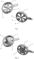
- Fig. 1 shows a first preferred embodiment of a flow element 3 for use in an extruder.
- the illustration at the top left corresponds to the view in the flow direction of the melt
- the illustration at the bottom right corresponds to the view from the opposite direction starting from the perforated plate.
- the inflow element 3 has a circular cross-sectional area and has an extension on its edge which is provided to move the inflow element 3.
- a flow cone 6 In the center of the cross-sectional area there is a flow cone 6, the base area of which points in the direction of the perforated plate and which tapers against the flow direction of the melt.
- six cover surfaces 5 run radially outward to the edge of the inflow element 3. Between the cover surfaces 5 there are open areas that form the passage surfaces 4 for the melt.
- the cover surfaces 5 become wider in the radial direction towards the edge as the circumference increases from the center to the edge.
- the base areas of the cover areas 5 are dimensioned such that they correspond to the passage areas 4.
- the cover surfaces 5 In the longitudinal section (perpendicular to the cross-sectional area), the cover surfaces 5 have a profile that has its widest extent on the base area facing the perforated plate and tapers against the flow direction of the melt. Melt hitting the inflow element 3 is thus directed away from the center through the conical shape of the inflow cone 6 and, due to the shape of the cover surfaces 5, is directed away from them to the edges of the cover surfaces 5 and thus onto the adjacent passage surfaces 4.
- a further preferred embodiment of a flow element 3 for use in an extruder is shown.
- This embodiment differs from that in Fig. 1 shown only in the geometric design of the inflow cone 6 and the cover surfaces 5.
- the inflow cone 6 is significantly larger in its diameter and in its axial extent than that of the embodiment Fig. 1 .
- the cover areas 5 and the passage areas 4 are correspondingly significantly smaller.
- a flow element 3 according to this embodiment therefore exposes a significantly smaller area of the perforated plate for the melt to flow through.
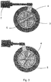
- FIG. 13 shows a plan view of a flow element 3 installed in an extruder according to the embodiment of FIG Fig. 1 viewed in the flow direction of the melt.
- the inflow element 3 is rotatably mounted in a flange. In order to move or rotate the inflow element 3, it is connected to an actuator 7.
- Fig. 4 is that in Fig. 1 and 3 explained inflow element 3 in the installed state shown partially cut away.
- the upper figure in Fig. 3 shows the flow element 3 in a first position in which there are holes in the perforated plate behind the passage surfaces 4, so that a first subset of holes in the perforated plate is exposed. A second subset of holes in the perforated plate is located behind the cover surfaces 5 and is thus closed.
- the flow element 3 compared to the position in the upper figure by 30 ° im Twisted counterclockwise. The previously open holes in the perforated plate are now covered by the cover surfaces 5, while the previously covered holes can now be traversed by the melt.
- the holes in the perforated plate are designed differently in the two subsets. Many small holes are arranged in the subset of holes that is open in the illustration above. In contrast, in the subset of holes that is open in the illustration below, fewer but larger holes are arranged.
- the device according to the invention makes it possible to switch between the two hole sizes without stopping the flow of melt in the extruder, ie without stopping the extruder. This enables flexible switching between control strategies without any loss of runtime.
- a preferred embodiment of the invention is shown schematically in an exploded view. Only the extruder outlet is shown of the extruder. The flow direction of the melt runs from left to right. At the outlet end of the extruder, a first plate 9 and a second plate 10 are flanged and firmly connected to the extruder.
- the second plate 10 has a recess in the interior between the upper and the lower end in which a perforated plate 2 is slidably mounted.
- the perforated plate 2 comprises two throughflow surfaces 8, both of which contain a multiplicity of throughflow openings.
- the outer contour of the throughflow surfaces 8 (envelope around the throughflow openings) is in each case circular and its cross section corresponds to the inner cross section of the flow channel 1 at this point.
- an actuator is provided, which can move the perforated plate essentially perpendicular to the flow channel 1 via a linear movement.
- a flow element 3 Arranged between the extruder outlet and the first plate 9 is a flow element 3 which can be rotated by a predetermined angle with the aid of an actuator 7.
- the inflow element 3 corresponds to that in Fig. 2 shown.
- sealing elements 11 are provided between the extruder outlet, inflow element 3, perforated plate 2 and second plate 10.
- a granulating tool 12 is provided, which rests against the perforated plate 2 and cuts the melt strands emerging through the through-flow openings into small-sized granules by a rotary movement.
Landscapes
- Engineering & Computer Science (AREA)
- Mechanical Engineering (AREA)
- Manufacturing & Machinery (AREA)
- Extrusion Moulding Of Plastics Or The Like (AREA)
Description
Die Erfindung betrifft einen Extruder umfassend ein Gehäuse mit einem Strömungskanal für eine Schmelze sowie eine den Strömungskanal austrittsseitig begrenzende Lochplatte. Gattungsgemäße Extruder und Lochplatten sind aus der Literatur bekannt. So beschreibt das Dokument
Um den Material- und Kapazitätsverlusten entgegenzuwirken sind Filtersiebe bekannt, die im Strömungsverlauf vor der Lochplatte im Inneren des Extruders auswechselbar eingesetzt sind. So offenbart das Dokument
In der Offenlegungsschrift
Es stellte sich die Aufgabe, einen gattungsgemäßen Extruder derart weiterzubilden, dass produktionsbedingte Materialverluste und Ausfallzeiten weiter als im Stand der Technik bekannt reduziert werden.The object was to develop a generic extruder in such a way that production-related material losses and downtimes are further reduced than known in the prior art.
Diese Aufgabe wird erfindungsgemäß gelöst durch einen Extruder umfassend ein Gehäuse mit einem Strömungskanal für eine Schmelze sowie eine den Strömungskanal austrittsseitig begrenzende Lochplatte, wobei in Strömungsrichtung der Schmelze vor der Lochplatte ein Anströmelement mit Durchtrittsflächen und Abdeckflächen derart verschiebbar angeordnet ist, dass bei einer Verschiebung des Anströmelements eine erste Teilmenge von Löchern der Lochplatte freigegeben und eine zweite Teilmenge von Löchern der Lochplatte verschlossen werden, wobei die Abdeckflächen (5) in einer bevorzugten Ausführungsform radial vom Zentrum des Anströmelements (3) zu seinem Rand verlaufen.This object is achieved according to the invention by an extruder comprising a housing with a flow channel for a melt as well as a perforated plate delimiting the flow channel on the outlet side, a flow element with passage surfaces and cover surfaces being displaceably arranged in front of the perforated plate in the flow direction of the melt so that when the flow element is displaced a first subset of holes in the perforated plate are released and a second subset of holes in the perforated plate are closed, the cover surfaces (5) extending radially from the center of the inflow element (3) to its edge in a preferred embodiment.
Unter einer Lochplatte wird im Rahmen der Erfindung das Bauteil verstanden, aus dem die Schmelze den Extruder verlässt, bevor sie der weiteren Verarbeitung zugeführt wird. Gegebenenfalls im Inneren des Extruders vorhandene Filter- oder Siebvorrichtungen sind keine "Lochplatten" im Sinne der Erfindung.In the context of the invention, a perforated plate is understood to mean the component from which the melt leaves the extruder before it is fed to further processing. Any filter or sieve devices present in the interior of the extruder are not "perforated plates" in the context of the invention.
Das Anströmelement dient dazu, die in Richtung des Extruderaustritts fließende Schmelze auf vorgegebene Bereiche der Lochplatte zu lenken. Dazu umfasst das Anströmelement Durchtrittsflächen, durch die die Schmelze strömen kann, sowie Abdeckflächen, die verhindern, dass die Schmelze auf in Strömungsrichtung hinter den Abdeckflächen liegende Bereiche der Lochplatte strömt.The flow element is used to direct the melt flowing in the direction of the extruder outlet onto predetermined areas of the perforated plate. For this purpose, the inflow element comprises passage areas through which the melt can flow, as well as cover areas which prevent the melt from flowing onto areas of the perforated plate that are located behind the cover areas in the flow direction.
In einer vorteilhaften Ausgestaltung weist das Anströmelement einen Anströmkegel auf, dessen Grundfläche in Richtung der Lochplatte weist, und der sich entgegen der Strömungsrichtung der Schmelze konisch verjüngt. Der Begriff "Kegel" ist in diesem Zusammenhang nicht streng mathematisch zu verstehen. Im Sinne der Erfindung kann der Anströmkegel die Form eines Kegels, eines Kegelstumpfes oder eine andere sich entgegen der Strömungsrichtung der Schmelze verjüngende Form aufweisen. Die Grundfläche kann dabei beispielsweise kreisförmig, ellipsenförmig oder eckig sein. Ein derartiger Anströmkegel lenkt die anströmende Schmelze radial seitlich auf die Durchströmflächen und Abdeckflächen und kann somit zur gleichmäßigen Verteilung der Schmelze dienen.In an advantageous embodiment, the inflow element has an inflow cone, the base area of which points in the direction of the perforated plate, and which tapers conically counter to the flow direction of the melt. The term "cone" is not to be understood strictly mathematically in this context. In the context of the invention, the flow cone can have the shape of a cone, a truncated cone or some other shape that tapers against the flow direction of the melt. The base area can be circular, elliptical or angular, for example. Such an inflow cone directs the inflowing melt radially laterally onto the throughflow surfaces and cover surfaces and can thus serve for the even distribution of the melt.
Die Verschiebung des Anströmelements kann beispielsweise lateral oder rotatorisch erfolgen, solange dabei unterschiedliche Teilmengen von Löchern der Lochplatte freigegeben bzw. verschlossen werden. In einer weiteren bevorzugten Ausgestaltung weist das Anströmelement eine kreisförmige Querschnittsfläche auf, und die Verschiebung erfolgt durch Verdrehen um den Mittelpunkt der Querschnittsfläche. Abhängig von der Anzahl, Größe und Geometrie der Durchtritts- und Abdeckflächen sowie des für die Verdrehung vorgesehenen Winkels können Teilmengen von Löchern der Lochplatte komplett oder partiell freigegeben bzw. verschlossen werden.The flow element can be shifted laterally or rotationally, for example, as long as different subsets of holes in the perforated plate are released or closed. In a further preferred embodiment, the inflow element has a circular cross-sectional area, and the displacement takes place by rotating around the center point of the cross-sectional area. Depending on the number, size and geometry of the passage and cover surfaces as well as the angle provided for the rotation, subsets of holes in the perforated plate can be completely or partially released or closed.
Anzahl, Größe und Geometrie der Durchtrittsflächen sowie der Abdeckflächen können unterschiedlich gestaltet und den Erfordernissen und Gegebenheiten im konkreten Fall angepasst sein. In einer bevorzugten Ausgestaltung verlaufen die Abdeckflächen radial vom Zentrum des Anströmelements zu seinem Rand. Vorzugsweise werden die Abdeckflächen in radialer Richtung zum Rand hin in dem Maße breiter, wie sich der Umfang vom Zentrum zum Rand vergrößert. Weiterhin ist bevorzugt, dass die Abdeckflächen im Längsschnitt ein Profil aufweisen, das seine breiteste Ausdehnung an der der Lochplatte zugewandten Grundfläche hat und sich entgegen der Strömungsrichtung der Schmelze verjüngt. Ein derartiges Profil hat den Vorteil, dass auf die Abdeckfläche strömende Schmelze von der Abdeckfläche weg zu ihren Rändern und somit auf die benachbarten Durchtrittsflächen gelenkt wird.The number, size and geometry of the passage areas and the cover areas can be designed differently and adapted to the requirements and conditions in the specific case. In a preferred embodiment, the cover surfaces run radially from the center of the inflow element to its edge. The cover surfaces are preferably in the radial direction broader towards the edge as the circumference increases from the center to the edge. It is also preferred that the cover surfaces have a profile in longitudinal section which has its widest extent on the base surface facing the perforated plate and tapers counter to the flow direction of the melt. Such a profile has the advantage that melt flowing onto the cover surface is directed away from the cover surface to its edges and thus onto the adjacent passage surfaces.
In einer weiteren vorteilhaften Ausführungsform berühren die Abdeckflächen zumindest mit ihren Kanten die Lochplatte. Dadurch wird zum einen vermieden, dass ein Teil der Schmelze zwischen der Abdeckfläche und der Lochplattenoberfläche hindurch unter die Abdeckfläche gelangen kann, und somit die Schmelze nur durch die dafür vorgesehenen Durchtrittsflächen strömen kann. Zum anderen können bei einer derartigen Ausführungsform die Kanten der Abdeckflächen gleichsam als Abstreifer verwendet werden, um währen der Verschiebung gegebenenfalls an der Oberfläche der Lochplatte anhaftendes Material abzuschaben, wodurch einer vorzeitigen Verstopfung der Öffnungen in der Lochplatte vorgebeugt wird.In a further advantageous embodiment, the cover surfaces touch the perforated plate at least with their edges. This avoids, on the one hand, that part of the melt can get between the cover surface and the perforated plate surface under the cover surface, and thus the melt can only flow through the passage surfaces provided for this purpose. On the other hand, in such an embodiment, the edges of the cover surfaces can be used as wipers in order to scrape off any material adhering to the surface of the perforated plate during the displacement, which prevents premature clogging of the openings in the perforated plate.
Die Verschiebung des Anströmelements kann manuell erfolgen, gegebenenfalls unter Zuhilfenahme von Werkzeugen wie Hebeln. Vorzugsweise erfolgt die Verschiebung unter Nutzung von Hilfsenergie, beispielsweise elektrischer, pneumatischer oder hydraulischer Hilfsenergie. Besonders bevorzugt erfolgt die Verschiebung des Anströmelements mit Hilfe eines Stellantriebs.The flow element can be shifted manually, if necessary with the aid of tools such as levers. The displacement is preferably carried out using auxiliary energy, for example electrical, pneumatic or hydraulic auxiliary energy. It is particularly preferable for the inflow element to be displaced with the aid of an actuator.
In einer vorteilhaften Ausgestaltung ist im oder am Gehäuse des Extruders mindestens ein Sensor vorhanden, der zur Erfassung einer Information über den Druck im Strömungskanal geeignet ist.In an advantageous embodiment, there is at least one sensor in or on the housing of the extruder that is suitable for detecting information about the pressure in the flow channel.
Aus der Information über den Druck im Strömungskanal lassen sich Informationen über den Verstopfungsgrad der in Betrieb befindlichen Durchströmfläche gewinnen.Information about the degree of blockage of the flow area in operation can be obtained from the information about the pressure in the flow channel.
In einer bevorzugten Ausführungsform werden diese Informationen mittels einer Einrichtung zur elektronischen Datenübertragung an eine Meldeeinrichtung übermittelt. Die Meldeeinrichtung kann sich in unmittelbarer Nähe des Extruders befinden, beispielsweise um optisch und/oder akustisch auf eine bevorstehende Verstopfung der Lochscheibe aufmerksam zu machen. Die Meldeeinrichtung kann aber auch räumlich entfernt vom Extruder sein, beispielsweise als optisch und/oder akustisch wahrnehmbare Anzeige in einem Prozessleitsystem.In a preferred embodiment, this information is transmitted to a reporting device by means of a device for electronic data transmission. The reporting device can be located in the immediate vicinity of the extruder, for example in order to visually and / or acoustically draw attention to an impending clogging of the perforated disk. The signaling device can, however, also be spatially remote from the extruder, for example as an optically and / or acoustically perceptible display in a process control system.
In einer bevorzugten Ausführungsform weist der erfindungsgemäße Extruder einen Stellantrieb zum Verschieben des Anströmelements, mindestens einen Sensor zur Erfassung eines Druckes im Strömungskanal sowie ein Steuerungsmodul auf, wobei das Steuerungsmodul derart eingerichtet ist, dass bei Erreichen eines vorgegebenen kritischen Wertes für den Druck oder für eine Druckdifferenz das Anströmelement mit Hilfe des Stellantriebs verschoben wird.In a preferred embodiment, the extruder according to the invention has an actuator for moving the inflow element, at least one sensor for detecting a pressure in the flow channel and a control module, the control module being set up in such a way that when a predetermined critical value for the pressure or for a pressure difference is reached the flow element is moved with the aid of the actuator.
In einer vorteilhaften Ausgestaltung ist der Sensor derart angeordnet und eingerichtet, dass der Absolutdruck im Strömungskanal bestimmt wird. In einer weiteren vorteilhaften Ausgestaltung sind mindestens zwei Sensoren vorgesehen, die derart angeordnet und eingerichtet sind, dass eine Druckdifferenz bestimmt wird. Der vorgegebene kritische Wert für den Druck oder für die Druckdifferenz wird vorzugsweise auf die jeweils behandelte Schmelze und die entsprechenden Prozessbedingungen abgestimmt. So kann beim Erfassen des Absolutdrucks als kritischer Wert beispielsweise ein Druck vorgegeben werden, der um einen bestimmten Betrag niedriger ist als der Druck, bei dem Sicherheitseinrichtungen wie ein Sicherheitsventil oder ein Abfahrventil ausgelöst werden.In an advantageous embodiment, the sensor is arranged and set up in such a way that the absolute pressure in the flow channel is determined. In a further advantageous embodiment at least two sensors are provided, which are arranged and set up in such a way that a pressure difference is determined. The predetermined critical value for the pressure or for the pressure difference is preferably matched to the melt treated in each case and the corresponding process conditions. For example, when the absolute pressure is recorded, a pressure can be specified as a critical value which is lower by a certain amount than the pressure at which safety devices such as a safety valve or a shut-off valve are triggered.
Das Steuerungsmodul kann in bekannter Weise verwirklicht sein, beispielsweise als separater Mikrocontroller, integriert in den Stellantrieb oder als Baustein in einem Prozessleitsystem.The control module can be implemented in a known manner, for example as a separate microcontroller, integrated into the actuator or as a component in a process control system.
Gegenüber bekannten Vorrichtungen weist die erfindungsgemäße Vorrichtung den Vorteil auf, dass die Produktionszeit zwischen zwei zur Reinigung erforderlichen Abstellungen des Extruders signifikant verlängert wird. So kann beispielsweise bei einer Aufteilung der Abdeckflächen und der Durchtrittsflächen im gleichen Verhältnis die Laufzeit des Extruders verdoppelt werden, da nach Verschmutzung der ersten Teilmenge von Löchern der Lochplatte noch eine zweite Teilmenge mit sauberen Löchern zur Verfügung steht. Ein weiterer Vorteil besteht darin, dass die Teilmengen von Löchern unterschiedlich gestaltet werden können, sodass durch die Verschiebung des Anströmelements zwischen zwei unterschiedlichen Produktqualitäten bzw. zwischen unterschiedlichen Produktionsverfahren umgeschaltet werden kann. In jedem Fall wird durch die erfindungsgemäße Vorrichtung die Verfügbarkeit der Anlage signifikant erhöht, dadurch die Kapazität gesteigert und Materialverlust vermieden.Compared to known devices, the device according to the invention has the advantage that the production time between two shutdowns of the extruder required for cleaning is significantly increased. For example, if the cover areas and the passage areas are divided in the same ratio, the running time of the extruder can be doubled, since after the first subset of holes in the perforated plate is soiled, a second subset with clean holes is available. Another advantage is that the subsets of holes can be designed differently, so that it is possible to switch between two different product qualities or between different production processes by shifting the flow element. In any case, the device according to the invention significantly increases the availability of the system, thereby increasing the capacity and avoiding material loss.
Die Erfindung wird im Folgenden mit Verweis auf die Zeichnungen näher erläutert. Die Zeichnungen sind als Prinzipdarstellungen zu verstehen. Sie stellen keine Beschränkung der Erfindung dar, beispielsweise im Hinblick auf konkrete Abmessungen oder Ausgestaltungsvarianten.The invention is explained in more detail below with reference to the drawings. The drawings are to be understood as schematic representations. They do not represent a restriction of the invention, for example with regard to specific dimensions or design variants.
- 11
- StrömungskanalFlow channel
- 22
- LochplattePerforated plate
- 33
- AnströmelementInflow element
- 44th
- Durchtrittsfläche(n)Passage area (s)
- 55
- Abdeckfläche(n)Cover area (s)
- 66
- AnströmkegelFlow cone
- 77th
- StellantriebActuator
- 88th
- Durchströmfläche(n) der LochplatteFlow area (s) of the perforated plate
- 99
- erste Plattefirst record
- 1010
- zweite Plattesecond plate
- 1111
- Dichtungpoetry
- 1212th
- GranulierwerkzeugGranulating tool
In dem dargestellten Beispiel werden die Abdeckflächen 5 in radialer Richtung zum Rand hin in dem Maße breiter, wie sich der Umfang vom Zentrum zum Rand vergrößert. Die Grundflächen der Abdeckflächen 5 sind so bemessen, dass sie den Durchtrittsflächen 4 entsprechen. Im Längsschnitt (senkrecht zur Querschnittsfläche) weisen die Abdeckflächen 5 ein Profil auf, das seine breiteste Ausdehnung an der der Lochplatte zugewandten Grundfläche hat und sich entgegen der Strömungsrichtung der Schmelze verjüngt. Auf das Anströmelement 3 treffende Schmelze wird somit zum einen durch die konische Form des Anströmkegels 6 vom Zentrum weg geleitet und zum anderen aufgrund der Formgebung der Abdeckflächen 5 von diesen weg zu den Rändern der Abdeckflächen 5 und somit auf die benachbarten Durchtrittsflächen 4 gelenkt.In the example shown, the cover surfaces 5 become wider in the radial direction towards the edge as the circumference increases from the center to the edge. The base areas of the
In
Die obere Abbildung in
In dem dargestellten Beispiel sind die Löcher der Lochplatte in den beiden Teilmengen unterschiedlich ausgeführt. In der Teilmenge von Löchern, die in der oberen Darstellung offen ist, sind viele kleine Löcher angeordnet. Dagegen sind in der Teilmenge von Löchern, die in der unteren Darstellung offen ist, weniger, aber größere Löcher angeordnet. Die erfindungsgemäße Vorrichtung ermöglicht es, zwischen den beiden Lochgrößen umzuschalten, ohne dabei den Schmelzefluss im Extruder anzuhalten, also den Extruder abzufahren. Dadurch kann ohne Laufzeiteinbußen flexibel zwischen Fahrweisen umgeschaltet werden.In the example shown, the holes in the perforated plate are designed differently in the two subsets. Many small holes are arranged in the subset of holes that is open in the illustration above. In contrast, in the subset of holes that is open in the illustration below, fewer but larger holes are arranged. The device according to the invention makes it possible to switch between the two hole sizes without stopping the flow of melt in the extruder, ie without stopping the extruder. This enables flexible switching between control strategies without any loss of runtime.
In
Die zweite Platte 10 weist zwischen dem oberen und dem unteren Ende im Inneren eine Aussparung auf, in der eine Lochplatte 2 verschiebbar gelagert ist. Die Lochplatte 2 umfasst zwei Durchströmflächen 8, die beide eine Vielzahl an Durchströmöffnungen enthalten. Die äußere Kontur der Durchströmflächen 8 (Einhüllende um die Durchströmöffnungen) ist jeweils kreisrund und entspricht in ihrem Querschnitt dem Innenquerschnitt des Strömungskanals 1 an dieser Stelle. Zum Verschieben der Lochplatte 2 ist ein Stellantrieb vorgesehen, der über eine Linearbewegung die Lochplatte im Wesentlichen senkrecht zum Strömungskanal 1 verschieben kann.The
Zwischen dem Extruderaustritt und der ersten Platte 9 ist ein Anströmelement 3 angeordnet, das mit Hilfe eines Stellantriebs 7 um einen vorgegebenen Winkel verdreht werden kann. In diesem Beispiel entspricht das Anströmelement 3 dem in
Claims (8)
- An extruder comprising a housing having a flow channel (1) for a melt and a perforated plate (2) delimiting the flow channel (1) on the outlet side, where an inlet flow element (3) having passage areas (4) and covering surfaces (5) is arranged so as to be movable ahead of the perforated plate (2) in the direction of flow of the melt in such a way that, when the inlet flow element (3) is moved, a first subset of holes in the perforated plate (2) is exposed and a second subset of holes in the perforated plate (2) is closed, wherein the inlet flow element (3) has an inlet flow cone (6), the base of which faces in the direction of the perforated plate (2) and which tapers conically counter to the direction of flow of the melt.
- The extruder according to claim 1, wherein the inlet flow element (3) has a circular cross-sectional area, and the movement is accomplished by rotation about the center of the cross-sectional area.
- The extruder according to claim 1, wherein the covering surfaces (5) extend radially from the center of the inlet flow element (3) to the rim thereof.
- The extruder according to claim 3, wherein the covering surfaces (5) have a profile in longitudinal section which has its widest extent at the base facing the perforated plate (2) and tapers counter to the direction of flow of the melt.
- The extruder according to claim 3 or 4, wherein the inlet flow element (3) has an inlet flow cone (6), the base of which faces in the direction of the perforated plate (2) and which tapers conically counter to the direction of flow of the melt.
- The extruder according to claim 3 or 4, wherein the inlet flow element (3) has a circular cross-sectional area, and the movement is accomplished by rotation about the center of the cross-sectional area.
- The extruder according to one of claims 1 to 6, wherein the covering surfaces (5) are in contact with the perforated plate (2) at least with their edges.
- The extruder according to one of claims 1 to 7, which furthermore has an actuator (7) for moving the inlet flow element (3), at least one sensor for detecting a pressure in the flow channel (1) and a control module, wherein the control module is designed in such a way that the inlet flow element (3) is moved with the aid of the actuator (7) when a predetermined critical value for the pressure or for a pressure difference is reached.
Applications Claiming Priority (2)
| Application Number | Priority Date | Filing Date | Title |
|---|---|---|---|
| DE102015226512 | 2015-12-22 | ||
| PCT/EP2016/080615 WO2017108475A1 (en) | 2015-12-22 | 2016-12-12 | Extruder comprising a deflection element for targeted flow against perforated plate regions |
Publications (2)
| Publication Number | Publication Date |
|---|---|
| EP3393751A1 EP3393751A1 (en) | 2018-10-31 |
| EP3393751B1 true EP3393751B1 (en) | 2021-02-17 |
Family
ID=57543036
Family Applications (1)
| Application Number | Title | Priority Date | Filing Date |
|---|---|---|---|
| EP16809800.2A Active EP3393751B1 (en) | 2015-12-22 | 2016-12-12 | Extruder with deflector element for guiding the mass flow to respective breaker plate sections |
Country Status (4)
| Country | Link |
|---|---|
| US (1) | US20190001527A1 (en) |
| EP (1) | EP3393751B1 (en) |
| CN (1) | CN108472853A (en) |
| WO (1) | WO2017108475A1 (en) |
Families Citing this family (2)
| Publication number | Priority date | Publication date | Assignee | Title |
|---|---|---|---|---|
| WO2020247215A1 (en) * | 2019-06-03 | 2020-12-10 | Nordson Corporation | Die plate heating/changing system and method for changing plates in a pelletizer |
| DE102021115905B4 (en) * | 2021-06-18 | 2023-04-27 | Gneuss Gmbh | Multi-way valve unit for plastic melts and other medium to high-viscosity liquids |
Citations (2)
| Publication number | Priority date | Publication date | Assignee | Title |
|---|---|---|---|---|
| US5045254A (en) * | 1989-01-23 | 1991-09-03 | Amoco Corporation | Process for producing tubular film from thermoplastic molten material |
| JPH04278325A (en) * | 1991-03-06 | 1992-10-02 | Kobe Steel Ltd | Molten material extruding device |
Family Cites Families (4)
| Publication number | Priority date | Publication date | Assignee | Title |
|---|---|---|---|---|
| JPS5927698B2 (en) * | 1977-11-28 | 1984-07-07 | 株式会社日本製鋼所 | Automatic "filter" mesh exchange device in plastic extrusion machine |
| US4237014A (en) * | 1979-03-12 | 1980-12-02 | Beringer Co., Inc. | Flowable material passage with interposable slide member |
| CN103128950A (en) * | 2011-11-24 | 2013-06-05 | 张家港市贝尔机械有限公司 | Pressure-equalizing hot granulator head |
| CN203171997U (en) * | 2013-04-27 | 2013-09-04 | 浙江精诚模具机械有限公司 | Mesh transmission type filter for melt purification of plastics extruding system |
-
2016
- 2016-12-12 EP EP16809800.2A patent/EP3393751B1/en active Active
- 2016-12-12 CN CN201680074704.0A patent/CN108472853A/en active Pending
- 2016-12-12 US US16/064,880 patent/US20190001527A1/en not_active Abandoned
- 2016-12-12 WO PCT/EP2016/080615 patent/WO2017108475A1/en not_active Ceased
Patent Citations (2)
| Publication number | Priority date | Publication date | Assignee | Title |
|---|---|---|---|---|
| US5045254A (en) * | 1989-01-23 | 1991-09-03 | Amoco Corporation | Process for producing tubular film from thermoplastic molten material |
| JPH04278325A (en) * | 1991-03-06 | 1992-10-02 | Kobe Steel Ltd | Molten material extruding device |
Also Published As
| Publication number | Publication date |
|---|---|
| CN108472853A (en) | 2018-08-31 |
| US20190001527A1 (en) | 2019-01-03 |
| WO2017108475A1 (en) | 2017-06-29 |
| EP3393751A1 (en) | 2018-10-31 |
Similar Documents
| Publication | Publication Date | Title |
|---|---|---|
| AT510191B1 (en) | DEVICE FOR DRYING GRANULAR GRAINS | |
| EP0672443B1 (en) | Control and filtering device for at least two partial fluid streams | |
| DE102012214185A1 (en) | Method and device for conveying conveyed goods with a rotary valve | |
| DE102008001635A1 (en) | Blending valve and device for the treatment of fluids | |
| EP2576180B1 (en) | Filtering apparatus for highly viscous media | |
| DE102014016634A1 (en) | Filtration device for filtering a fluid | |
| DE10326487A1 (en) | Device for providing a melt | |
| DE102018120445B3 (en) | Filtration device for highly viscous media | |
| EP0433587A2 (en) | Screen changer apparatus with cylindrical screens | |
| EP3393751B1 (en) | Extruder with deflector element for guiding the mass flow to respective breaker plate sections | |
| DE2522078A1 (en) | SCREEN DEVICE, IN PARTICULAR FOR PLASTIC PROCESSING EXTRUDER | |
| AT521976B1 (en) | Melt filter | |
| EP3393752B1 (en) | Extruder with slidable breaker plate | |
| EP1082205B1 (en) | Filter device for extruders and injection moulding machines | |
| DE19612790C2 (en) | Device for filtering a fluid | |
| EP0875357B1 (en) | Filter device for extruders and injection machines | |
| DE4218756C1 (en) | Injection moulding machine and extrusion press filter appts. for thermoplastics - comprises barrier member in inlet channel prior to sieve bolt and housing for unimpeded plastic flow in open barrier position, for efficient continual working | |
| DE19834302C2 (en) | Filter device for extrusion presses and injection molding machines | |
| DE19730574C1 (en) | Filter unit for prolonged operation feeding extruders | |
| DE102010052153A1 (en) | Device for preventing the uncontrolled discharge of melt from a nozzle plate | |
| EP2501531B1 (en) | Apparatus for granulation | |
| EP2364761B1 (en) | Backwashable filter assembly | |
| DE3239493A1 (en) | Spray nozzle | |
| EP1499489B1 (en) | Filtration and/or drainage device, method for filtrating and/or draining and use of the device | |
| EP1762364A2 (en) | Device for filtering a fluid, especially for plastic-processing installations |
Legal Events
| Date | Code | Title | Description |
|---|---|---|---|
| STAA | Information on the status of an ep patent application or granted ep patent |
Free format text: STATUS: UNKNOWN |
|
| STAA | Information on the status of an ep patent application or granted ep patent |
Free format text: STATUS: THE INTERNATIONAL PUBLICATION HAS BEEN MADE |
|
| PUAI | Public reference made under article 153(3) epc to a published international application that has entered the european phase |
Free format text: ORIGINAL CODE: 0009012 |
|
| STAA | Information on the status of an ep patent application or granted ep patent |
Free format text: STATUS: REQUEST FOR EXAMINATION WAS MADE |
|
| 17P | Request for examination filed |
Effective date: 20180723 |
|
| AK | Designated contracting states |
Kind code of ref document: A1 Designated state(s): AL AT BE BG CH CY CZ DE DK EE ES FI FR GB GR HR HU IE IS IT LI LT LU LV MC MK MT NL NO PL PT RO RS SE SI SK SM TR |
|
| AX | Request for extension of the european patent |
Extension state: BA ME |
|
| DAV | Request for validation of the european patent (deleted) | ||
| DAX | Request for extension of the european patent (deleted) | ||
| REG | Reference to a national code |
Ref country code: DE Ref legal event code: R079 Ref document number: 502016012403 Country of ref document: DE Free format text: PREVIOUS MAIN CLASS: B29C0047700000 Ipc: B29C0048695000 |
|
| GRAP | Despatch of communication of intention to grant a patent |
Free format text: ORIGINAL CODE: EPIDOSNIGR1 |
|
| STAA | Information on the status of an ep patent application or granted ep patent |
Free format text: STATUS: GRANT OF PATENT IS INTENDED |
|
| RIC1 | Information provided on ipc code assigned before grant |
Ipc: B29C 48/92 20190101ALI20200820BHEP Ipc: B29B 9/06 20060101ALN20200820BHEP Ipc: B29C 48/345 20190101ALI20200820BHEP Ipc: B29C 48/695 20190101AFI20200820BHEP Ipc: B29C 48/05 20190101ALI20200820BHEP Ipc: B29C 48/255 20190101ALI20200820BHEP |
|
| RIC1 | Information provided on ipc code assigned before grant |
Ipc: B29C 48/695 20190101AFI20200908BHEP Ipc: B29C 48/05 20190101ALI20200908BHEP Ipc: B29B 9/06 20060101ALN20200908BHEP Ipc: B29C 48/92 20190101ALI20200908BHEP Ipc: B29C 48/345 20190101ALI20200908BHEP Ipc: B29C 48/255 20190101ALI20200908BHEP |
|
| INTG | Intention to grant announced |
Effective date: 20200923 |
|
| GRAS | Grant fee paid |
Free format text: ORIGINAL CODE: EPIDOSNIGR3 |
|
| GRAA | (expected) grant |
Free format text: ORIGINAL CODE: 0009210 |
|
| STAA | Information on the status of an ep patent application or granted ep patent |
Free format text: STATUS: THE PATENT HAS BEEN GRANTED |
|
| AK | Designated contracting states |
Kind code of ref document: B1 Designated state(s): AL AT BE BG CH CY CZ DE DK EE ES FI FR GB GR HR HU IE IS IT LI LT LU LV MC MK MT NL NO PL PT RO RS SE SI SK SM TR |
|
| REG | Reference to a national code |
Ref country code: GB Ref legal event code: FG4D Free format text: NOT ENGLISH |
|
| REG | Reference to a national code |
Ref country code: CH Ref legal event code: EP |
|
| REG | Reference to a national code |
Ref country code: DE Ref legal event code: R096 Ref document number: 502016012403 Country of ref document: DE |
|
| REG | Reference to a national code |
Ref country code: AT Ref legal event code: REF Ref document number: 1360909 Country of ref document: AT Kind code of ref document: T Effective date: 20210315 |
|
| REG | Reference to a national code |
Ref country code: IE Ref legal event code: FG4D Free format text: LANGUAGE OF EP DOCUMENT: GERMAN |
|
| REG | Reference to a national code |
Ref country code: LT Ref legal event code: MG9D |
|
| REG | Reference to a national code |
Ref country code: NL Ref legal event code: MP Effective date: 20210217 |
|
| PG25 | Lapsed in a contracting state [announced via postgrant information from national office to epo] |
Ref country code: LT Free format text: LAPSE BECAUSE OF FAILURE TO SUBMIT A TRANSLATION OF THE DESCRIPTION OR TO PAY THE FEE WITHIN THE PRESCRIBED TIME-LIMIT Effective date: 20210217 Ref country code: BG Free format text: LAPSE BECAUSE OF FAILURE TO SUBMIT A TRANSLATION OF THE DESCRIPTION OR TO PAY THE FEE WITHIN THE PRESCRIBED TIME-LIMIT Effective date: 20210517 Ref country code: GR Free format text: LAPSE BECAUSE OF FAILURE TO SUBMIT A TRANSLATION OF THE DESCRIPTION OR TO PAY THE FEE WITHIN THE PRESCRIBED TIME-LIMIT Effective date: 20210518 Ref country code: FI Free format text: LAPSE BECAUSE OF FAILURE TO SUBMIT A TRANSLATION OF THE DESCRIPTION OR TO PAY THE FEE WITHIN THE PRESCRIBED TIME-LIMIT Effective date: 20210217 Ref country code: HR Free format text: LAPSE BECAUSE OF FAILURE TO SUBMIT A TRANSLATION OF THE DESCRIPTION OR TO PAY THE FEE WITHIN THE PRESCRIBED TIME-LIMIT Effective date: 20210217 Ref country code: NO Free format text: LAPSE BECAUSE OF FAILURE TO SUBMIT A TRANSLATION OF THE DESCRIPTION OR TO PAY THE FEE WITHIN THE PRESCRIBED TIME-LIMIT Effective date: 20210517 Ref country code: PT Free format text: LAPSE BECAUSE OF FAILURE TO SUBMIT A TRANSLATION OF THE DESCRIPTION OR TO PAY THE FEE WITHIN THE PRESCRIBED TIME-LIMIT Effective date: 20210617 |
|
| PG25 | Lapsed in a contracting state [announced via postgrant information from national office to epo] |
Ref country code: LV Free format text: LAPSE BECAUSE OF FAILURE TO SUBMIT A TRANSLATION OF THE DESCRIPTION OR TO PAY THE FEE WITHIN THE PRESCRIBED TIME-LIMIT Effective date: 20210217 Ref country code: PL Free format text: LAPSE BECAUSE OF FAILURE TO SUBMIT A TRANSLATION OF THE DESCRIPTION OR TO PAY THE FEE WITHIN THE PRESCRIBED TIME-LIMIT Effective date: 20210217 Ref country code: RS Free format text: LAPSE BECAUSE OF FAILURE TO SUBMIT A TRANSLATION OF THE DESCRIPTION OR TO PAY THE FEE WITHIN THE PRESCRIBED TIME-LIMIT Effective date: 20210217 Ref country code: NL Free format text: LAPSE BECAUSE OF FAILURE TO SUBMIT A TRANSLATION OF THE DESCRIPTION OR TO PAY THE FEE WITHIN THE PRESCRIBED TIME-LIMIT Effective date: 20210217 Ref country code: SE Free format text: LAPSE BECAUSE OF FAILURE TO SUBMIT A TRANSLATION OF THE DESCRIPTION OR TO PAY THE FEE WITHIN THE PRESCRIBED TIME-LIMIT Effective date: 20210217 |
|
| PG25 | Lapsed in a contracting state [announced via postgrant information from national office to epo] |
Ref country code: IS Free format text: LAPSE BECAUSE OF FAILURE TO SUBMIT A TRANSLATION OF THE DESCRIPTION OR TO PAY THE FEE WITHIN THE PRESCRIBED TIME-LIMIT Effective date: 20210617 |
|
| PG25 | Lapsed in a contracting state [announced via postgrant information from national office to epo] |
Ref country code: SM Free format text: LAPSE BECAUSE OF FAILURE TO SUBMIT A TRANSLATION OF THE DESCRIPTION OR TO PAY THE FEE WITHIN THE PRESCRIBED TIME-LIMIT Effective date: 20210217 Ref country code: CZ Free format text: LAPSE BECAUSE OF FAILURE TO SUBMIT A TRANSLATION OF THE DESCRIPTION OR TO PAY THE FEE WITHIN THE PRESCRIBED TIME-LIMIT Effective date: 20210217 Ref country code: EE Free format text: LAPSE BECAUSE OF FAILURE TO SUBMIT A TRANSLATION OF THE DESCRIPTION OR TO PAY THE FEE WITHIN THE PRESCRIBED TIME-LIMIT Effective date: 20210217 |
|
| REG | Reference to a national code |
Ref country code: DE Ref legal event code: R097 Ref document number: 502016012403 Country of ref document: DE |
|
| PG25 | Lapsed in a contracting state [announced via postgrant information from national office to epo] |
Ref country code: DK Free format text: LAPSE BECAUSE OF FAILURE TO SUBMIT A TRANSLATION OF THE DESCRIPTION OR TO PAY THE FEE WITHIN THE PRESCRIBED TIME-LIMIT Effective date: 20210217 Ref country code: RO Free format text: LAPSE BECAUSE OF FAILURE TO SUBMIT A TRANSLATION OF THE DESCRIPTION OR TO PAY THE FEE WITHIN THE PRESCRIBED TIME-LIMIT Effective date: 20210217 Ref country code: SK Free format text: LAPSE BECAUSE OF FAILURE TO SUBMIT A TRANSLATION OF THE DESCRIPTION OR TO PAY THE FEE WITHIN THE PRESCRIBED TIME-LIMIT Effective date: 20210217 |
|
| PLBE | No opposition filed within time limit |
Free format text: ORIGINAL CODE: 0009261 |
|
| STAA | Information on the status of an ep patent application or granted ep patent |
Free format text: STATUS: NO OPPOSITION FILED WITHIN TIME LIMIT |
|
| 26N | No opposition filed |
Effective date: 20211118 |
|
| PG25 | Lapsed in a contracting state [announced via postgrant information from national office to epo] |
Ref country code: ES Free format text: LAPSE BECAUSE OF FAILURE TO SUBMIT A TRANSLATION OF THE DESCRIPTION OR TO PAY THE FEE WITHIN THE PRESCRIBED TIME-LIMIT Effective date: 20210217 Ref country code: AL Free format text: LAPSE BECAUSE OF FAILURE TO SUBMIT A TRANSLATION OF THE DESCRIPTION OR TO PAY THE FEE WITHIN THE PRESCRIBED TIME-LIMIT Effective date: 20210217 |
|
| PG25 | Lapsed in a contracting state [announced via postgrant information from national office to epo] |
Ref country code: SI Free format text: LAPSE BECAUSE OF FAILURE TO SUBMIT A TRANSLATION OF THE DESCRIPTION OR TO PAY THE FEE WITHIN THE PRESCRIBED TIME-LIMIT Effective date: 20210217 |
|
| PG25 | Lapsed in a contracting state [announced via postgrant information from national office to epo] |
Ref country code: IT Free format text: LAPSE BECAUSE OF FAILURE TO SUBMIT A TRANSLATION OF THE DESCRIPTION OR TO PAY THE FEE WITHIN THE PRESCRIBED TIME-LIMIT Effective date: 20210217 |
|
| PG25 | Lapsed in a contracting state [announced via postgrant information from national office to epo] |
Ref country code: IS Free format text: LAPSE BECAUSE OF FAILURE TO SUBMIT A TRANSLATION OF THE DESCRIPTION OR TO PAY THE FEE WITHIN THE PRESCRIBED TIME-LIMIT Effective date: 20210617 |
|
| PG25 | Lapsed in a contracting state [announced via postgrant information from national office to epo] |
Ref country code: MC Free format text: LAPSE BECAUSE OF FAILURE TO SUBMIT A TRANSLATION OF THE DESCRIPTION OR TO PAY THE FEE WITHIN THE PRESCRIBED TIME-LIMIT Effective date: 20210217 |
|
| REG | Reference to a national code |
Ref country code: CH Ref legal event code: PL |
|
| GBPC | Gb: european patent ceased through non-payment of renewal fee |
Effective date: 20211212 |
|
| REG | Reference to a national code |
Ref country code: BE Ref legal event code: MM Effective date: 20211231 |
|
| PG25 | Lapsed in a contracting state [announced via postgrant information from national office to epo] |
Ref country code: LU Free format text: LAPSE BECAUSE OF NON-PAYMENT OF DUE FEES Effective date: 20211212 Ref country code: IE Free format text: LAPSE BECAUSE OF NON-PAYMENT OF DUE FEES Effective date: 20211212 Ref country code: GB Free format text: LAPSE BECAUSE OF NON-PAYMENT OF DUE FEES Effective date: 20211212 |
|
| PG25 | Lapsed in a contracting state [announced via postgrant information from national office to epo] |
Ref country code: FR Free format text: LAPSE BECAUSE OF NON-PAYMENT OF DUE FEES Effective date: 20211231 Ref country code: BE Free format text: LAPSE BECAUSE OF NON-PAYMENT OF DUE FEES Effective date: 20211231 |
|
| PG25 | Lapsed in a contracting state [announced via postgrant information from national office to epo] |
Ref country code: LI Free format text: LAPSE BECAUSE OF NON-PAYMENT OF DUE FEES Effective date: 20211231 Ref country code: CH Free format text: LAPSE BECAUSE OF NON-PAYMENT OF DUE FEES Effective date: 20211231 |
|
| REG | Reference to a national code |
Ref country code: AT Ref legal event code: MM01 Ref document number: 1360909 Country of ref document: AT Kind code of ref document: T Effective date: 20211212 |
|
| PG25 | Lapsed in a contracting state [announced via postgrant information from national office to epo] |
Ref country code: AT Free format text: LAPSE BECAUSE OF NON-PAYMENT OF DUE FEES Effective date: 20211212 |
|
| PG25 | Lapsed in a contracting state [announced via postgrant information from national office to epo] |
Ref country code: CY Free format text: LAPSE BECAUSE OF FAILURE TO SUBMIT A TRANSLATION OF THE DESCRIPTION OR TO PAY THE FEE WITHIN THE PRESCRIBED TIME-LIMIT Effective date: 20210217 |
|
| PG25 | Lapsed in a contracting state [announced via postgrant information from national office to epo] |
Ref country code: HU Free format text: LAPSE BECAUSE OF FAILURE TO SUBMIT A TRANSLATION OF THE DESCRIPTION OR TO PAY THE FEE WITHIN THE PRESCRIBED TIME-LIMIT; INVALID AB INITIO Effective date: 20161212 |
|
| PG25 | Lapsed in a contracting state [announced via postgrant information from national office to epo] |
Ref country code: MK Free format text: LAPSE BECAUSE OF FAILURE TO SUBMIT A TRANSLATION OF THE DESCRIPTION OR TO PAY THE FEE WITHIN THE PRESCRIBED TIME-LIMIT Effective date: 20210217 |
|
| PGFP | Annual fee paid to national office [announced via postgrant information from national office to epo] |
Ref country code: DE Payment date: 20231227 Year of fee payment: 8 |
|
| PG25 | Lapsed in a contracting state [announced via postgrant information from national office to epo] |
Ref country code: MT Free format text: LAPSE BECAUSE OF FAILURE TO SUBMIT A TRANSLATION OF THE DESCRIPTION OR TO PAY THE FEE WITHIN THE PRESCRIBED TIME-LIMIT Effective date: 20210217 |
|
| REG | Reference to a national code |
Ref country code: DE Ref legal event code: R119 Ref document number: 502016012403 Country of ref document: DE |
|
| PG25 | Lapsed in a contracting state [announced via postgrant information from national office to epo] |
Ref country code: DE Free format text: LAPSE BECAUSE OF NON-PAYMENT OF DUE FEES Effective date: 20250701 |