EP3393582B1 - Intensity modulated proton therapy (impt) plan optimization based at least on internal organ anticipated movement and/or expected deformation - Google Patents
Intensity modulated proton therapy (impt) plan optimization based at least on internal organ anticipated movement and/or expected deformation Download PDFInfo
- Publication number
- EP3393582B1 EP3393582B1 EP16819670.7A EP16819670A EP3393582B1 EP 3393582 B1 EP3393582 B1 EP 3393582B1 EP 16819670 A EP16819670 A EP 16819670A EP 3393582 B1 EP3393582 B1 EP 3393582B1
- Authority
- EP
- European Patent Office
- Prior art keywords
- dose distribution
- internal organ
- image
- deformation
- proton therapy
- Prior art date
- Legal status (The legal status is an assumption and is not a legal conclusion. Google has not performed a legal analysis and makes no representation as to the accuracy of the status listed.)
- Active
Links
Images


Classifications
-
- A—HUMAN NECESSITIES
- A61—MEDICAL OR VETERINARY SCIENCE; HYGIENE
- A61N—ELECTROTHERAPY; MAGNETOTHERAPY; RADIATION THERAPY; ULTRASOUND THERAPY
- A61N5/00—Radiation therapy
- A61N5/10—X-ray therapy; Gamma-ray therapy; Particle-irradiation therapy
- A61N5/103—Treatment planning systems
- A61N5/1031—Treatment planning systems using a specific method of dose optimization
-
- A—HUMAN NECESSITIES
- A61—MEDICAL OR VETERINARY SCIENCE; HYGIENE
- A61N—ELECTROTHERAPY; MAGNETOTHERAPY; RADIATION THERAPY; ULTRASOUND THERAPY
- A61N5/00—Radiation therapy
- A61N5/10—X-ray therapy; Gamma-ray therapy; Particle-irradiation therapy
- A61N5/103—Treatment planning systems
- A61N5/1037—Treatment planning systems taking into account the movement of the target, e.g. 4D-image based planning
-
- A—HUMAN NECESSITIES
- A61—MEDICAL OR VETERINARY SCIENCE; HYGIENE
- A61N—ELECTROTHERAPY; MAGNETOTHERAPY; RADIATION THERAPY; ULTRASOUND THERAPY
- A61N5/00—Radiation therapy
- A61N5/10—X-ray therapy; Gamma-ray therapy; Particle-irradiation therapy
- A61N5/103—Treatment planning systems
- A61N5/1039—Treatment planning systems using functional images, e.g. PET or MRI
-
- A—HUMAN NECESSITIES
- A61—MEDICAL OR VETERINARY SCIENCE; HYGIENE
- A61N—ELECTROTHERAPY; MAGNETOTHERAPY; RADIATION THERAPY; ULTRASOUND THERAPY
- A61N5/00—Radiation therapy
- A61N5/10—X-ray therapy; Gamma-ray therapy; Particle-irradiation therapy
- A61N5/1042—X-ray therapy; Gamma-ray therapy; Particle-irradiation therapy with spatial modulation of the radiation beam within the treatment head
- A61N5/1045—X-ray therapy; Gamma-ray therapy; Particle-irradiation therapy with spatial modulation of the radiation beam within the treatment head using a multi-leaf collimator, e.g. for intensity modulated radiation therapy or IMRT
-
- A—HUMAN NECESSITIES
- A61—MEDICAL OR VETERINARY SCIENCE; HYGIENE
- A61N—ELECTROTHERAPY; MAGNETOTHERAPY; RADIATION THERAPY; ULTRASOUND THERAPY
- A61N5/00—Radiation therapy
- A61N5/10—X-ray therapy; Gamma-ray therapy; Particle-irradiation therapy
- A61N5/1048—Monitoring, verifying, controlling systems and methods
- A61N2005/1074—Details of the control system, e.g. user interfaces
-
- A—HUMAN NECESSITIES
- A61—MEDICAL OR VETERINARY SCIENCE; HYGIENE
- A61N—ELECTROTHERAPY; MAGNETOTHERAPY; RADIATION THERAPY; ULTRASOUND THERAPY
- A61N5/00—Radiation therapy
- A61N5/10—X-ray therapy; Gamma-ray therapy; Particle-irradiation therapy
- A61N2005/1085—X-ray therapy; Gamma-ray therapy; Particle-irradiation therapy characterised by the type of particles applied to the patient
- A61N2005/1087—Ions; Protons
Definitions
- the following generally relates intensity modulated proton therapy (IMPT), and more particularly to optimizing an IMPT plan based at least on internal organ anticipated movement and/or expected deformation.
- IMPT intensity modulated proton therapy
- Intensity modulated proton therapy uses a beam of protons to irradiate diseased tissue, e.g., in the treatment of cancer. Failing to account for errors such as range and setup uncertainties in the IMPT plan may result in a delivered dose distribution that is inferior to the planned dose distribution.
- Range uncertainty corresponds to the uncertainty of the location of the Bragg peak with respect to anatomical structures (i.e., the range of a proton beam in the patient). This uncertainty can be from the uncertainty in CT Hounsfield units and the conversion to stopping power, artifacts in the CT image, and geometric changes of the patient. Setup uncertainty is due to a positional shift of the patient, which may cause misalignment of dose contributions from different beam directions and misalignment of density heterogeneities.
- RO Robust Optimization
- Setup uncertainty can be modeled by simulating a set of independent uncertainty cases that mimic whole body movement of the patient in six directions (three pair of positive and negative coordinates).
- the RO minimizes a total objective value (RO OBV), which includes a clinical objective component (Nominal Plan OBV) and a patient setup error component (Setup Error OBV).
- RO OBV total objective value
- Nominal Plan OBV Nominal Plan OBV
- Setup Error OBV Setup Error OBV
- +X error OBV is the objective value obtained from the dose statistics when the patient is shifted in a positive X direction by a factor specified by the user.
- Non-limiting examples of determining error and IMPT planning are described in Goitein, "Calculation of uncertainty in the dose delivered during radiation therapy," Med. Phys. 12, 608-612 (1985 ), Unkelbach et al., “Accounting for range uncertainties in the optimization of intensity modulated proton therapy, Phys. Med. Biol. 52 (2007) 2755-2773 (2007 ), and Unkelbach et al. "Reducing the sensitivity of IMPT treatment plans to setup errors and range uncertainties via probabilistic treatment planning" American Association of Physicists in Medicine (2009 ).
- EQUATION 1 is well-suited for setup errors such as whole body patient movement, e.g., three millimeters (3 mm) with the modern immobilization devices.
- EQUATION 1 does not take into account internal organ movement and/or deformation, such as in the case of the bladder or rectum, which tends to be of a large magnitude relative to setup errors, and the probability of occurrence for this error tends to increase over time.
- such movement and/or deformation may result in a wrong dose due to a positional change with respect to beams.
- US8644571 describes the therapeutic treatment of a patient using IMPT.
- a method of creating a proton treatment plan is presented that divides volumes of interest into sub-volumes, applies does constraints to the sub-volumes, finds one or more feasible configurations of a proton therapy system, and selects a proton beam configuration.
- US2004/254773 describes the use of intensity modulated radiation therapy (IMRT) of targets subject to respiratory motion.
- IMRT intensity modulated radiation therapy
- a method in one aspect, includes generating a nominal dose distribution based on an image and clinical goals. The method further includes generating a setup error dose distribution based on range and setup uncertainties. The method further includes generating a dose distribution for a parameter of an internal organ. The method further includes optimizing a planned dose distribution of an intensity modulated proton therapy plan by minimizing a total objective value including the nominal dose distribution, the setup error dose distribution dose distribution, and the dose distribution for the internal organ. The method further includes generating a final dose distribution for the intensity modulated proton therapy plan based on beam parameters of the optimized planned dose distribution. The method further includes controlling a proton therapy apparatus configured to deliver proton therapy based on the intensity modulated proton therapy plan with the optimized planned dose distribution.
- a system in another aspect, includes a proton therapy apparatus configured to deliver proton therapy and a controller configured to control the proton therapy apparatus.
- the system further includes a treatment planner configured to generate an optimized intensity modulated proton therapy plan based on an input image, a nominal dose distribution, a setup error dose distribution, and a dose distribution for at least one of an internal organ movement or an internal organ deformation.
- the system further includes a console (122) configured to instruct the controller to control the proton therapy apparatus to transmit a proton beam based on the optimized intensity modulated proton therapy plan.
- a non-transitory computer readable medium is encoded with computer executable instructions, which when executed by a processor, causes the processor to: receive an image, receive a first input indicative of a nominal dose distribution for the image and clinical goals, receive a second input indicative of a whole body dose distribution for range and setup uncertainties, receive a third input indicative of an anticipated movement of an internal organ, receive a fourth input indicative of an expected deformation of the internal organ, warp the image based on the anticipated movement and the expected deformation, generating a warped image, compute a dose distribution for the warped image, optimize a planned dose distribution of an intensity modulated proton therapy based on the nominal dose distribution, the whole body movement distribution and the dose distribution for the anticipated movement and the expected deformation, export beam parameters obtained from the optimization to the received image, and generate a final dose distribution for the intensity modulated proton therapy plan based the beam parameters.
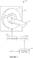
- FIGURE 1 schematically illustrates a therapy system 100 configured for intensity modulated proton therapy (IMPT.
- IMPT intensity modulated proton therapy
- a stationary gantry 102 rotatably supports a rotating gantry 104, which rotates with respect to a rotation axis about a treatment region 106.
- a nozzle 110 houses beam modifying components and delivers the proton beam.
- a snout 112 supports the aperture and compensator.
- a support 114 supports a portion of a subject in the treatment region 106.
- a proton source such as a 70 MeV proton accelerator, produces a proton beam.
- An operator console 122 includes human readable output devices such as a display monitor and input devices such as a keyboard and/or mouse. Software accessible on and executable by a processor of the console 122 allows the operator to control an operation of the therapy system 100.
- a controller 124 is configured to control rotation of the rotating gantry 104 and the subject support 116 and deliver of treatment protons by the proton source during a treatment.
- a treatment planner 126 creates IMPT treatment plans. As described in greater detail below, in one instance the treatment planner 126 is configured to optimize IMPT treatment plans based at least on internal organ movement and/or deformation. For example, in one instance the treatment planner 126 is configured to optimize IMPT treatment plans based on set up error and internal organ movement and/or deformation. In other embodiments, the treatment planner 126 is configured to optimize IMPT treatment plans based on more or less, additional or different, etc. features.
- the treatment planner 126 can be implemented via one or more processors (e.g., micro-processor, central processing unit, controller, etc.) executing one or more computer readable instructions.
- the one or more computer readable instructions are encoded on non-transitory computer readable storage medium such a physical memory and/or other non-transitory medium.
- at least one of the computer readable instructions can be carried by a carrier waver, a signal and/or other transitory medium.
- FIGURE 2 illustrates a non-limiting example of the treatment planner 126.
- the treatment planner 126 receives, as input, an image and clinical (user specified) goals.
- the image can be a computed tomography (CT), magnetic resonance (MR), positron emission tomography (PET), and/or other modality image.
- the image can be received from an imaging system, a data repository (e.g., picture archiving and communication system (PACS), a radiology information system (RIS), etc.), local memory, etc.
- Examples of clinical goals include a specific machine parameter setting (e.g., number of spots, spot monitor unit (MU), etc.), dose-volume histogram (DVH), dose distribution and a Composite Objective Value.
- a nominal plan generator 202 is configured to generate an optimized nominal IMPT plan based on the image and the clinical goals.
- the nominal plan includes an estimated nominal dose distribution, e.g., dose statistics of each region of interest (ROI).
- ROI region of interest
- the treatment planner 126 further receives, as input, anticipated ROI movement in one or more dimensions and/or an expected worst case of deformation for the ROI.
- GUIs 300 and 400 for entering organ movement and organ deformation in three-dimensions are illustrated. From FIGURE 3 , the GUI 300 includes a first field 302 for selecting a ROI 304 from a pre-determined list, and fields 306, 308 and 310 for entering expected organ movement along Antero-posterior (AP) 312, Superior-inferior (SI) 314 and Medio-Lateral (ML) 316 directions.
- AP Antero-posterior
- SI Superior-inferior
- ML Medio-Lateral
- the GUI 400 includes a first field 402 for selecting a ROI 404, and fields 406, 408 and 410 for entering a range of deformation along AP 412, SI 414 and ML 416 directions.
- a location and/or a size/shape of the/ ROI can be entered and/or edited.
- an image warper 204 warps the input image based on the anticipated ROI movement and/or the expected ROI deformation, producing a warped image or model.
- the input is converted to a set of deformation vector fields (DVFs), which is applied on an external contour of the ROI to warp the ROI (ROI-warping), the region of the image contained within the ROI (ROI density-warping) and/or regions in a predetermined vicinity about the deformed ROI (neighborhood density-warping).
- This will produce warping inside the ROI as well as in the regions adjacent to the ROI.
- the neighborhood density-warping is done by assuming a simple elastic expansion-contraction model. In this approach, as shown in FIGURE 5 , a neighborhood region 500 contracts if an ROI 504 expands, and, as shown in FIGURE 6 , the neighborhood region 500 expands if the ROI 502 contracts.
- the elastic model for neighborhood-density warping can in turn obey different models based on user preference, a default, etc.
- a first is a simple spring expansion model in which the displacement is shared equally starting from the fixed point to the loaded point.
- Another is a damped spring expansion model in which the displacement is more at a loaded point and gradually reduces towards a fixed point.
- the simple spring is well-suited for instances where the expected organ movement and/or deformation causes an equal and linear contraction or expansion in the nearest neighborhood as well as in the farthest regions from the deformed organ.
- the damped spring model is well-suited for instances where the expected expansion/contraction resulting from organ movement or deformation is greater in the nearest neighborhood and less farther from the organ.
- an organ movement and/or deformation analyzer 206 processes the ROI in the warped image and generates dose distributions for the ROI movement and/or deformation.
- the treatment planner 126 further receives, as input, a set of setup uncertainty such as an estimate of whole body movement of the patient in six directions (three pair of positive and negative coordinates), range uncertainty, etc.
- a setup error analyzer 208 processes the setup error (range and setup uncertainty) and generates a dose distribution optimized for the setup error.
- a robustness optimizer 210 processes the estimated nominal dose distribution, the dose distributions for the setup error, and the dose distributions for the ROI movement and/or deformation.
- EQUATION 2 provides an example RO optimization for computing a RO OBV that takes into account the ROI movement and/or deformation.
- RO OBV Nominal Plan OBV + Setup Error OBV + Organ Movement OBV + Organ deformation OBV
- each objective value represents a respective uncertainty scenario, e.g., Organ B (+X error OBV) is the objective value obtained from the dose statistics when the organ B is in displaced place by a factor specified by the user.
- each objective value represents the respective uncertainty scenario, e.g., Organ A (X contraction OBV) is the objective value obtained from the dose statistics when the organ A is in contracted state.
- the Organ Movement OBV component is omitted from EQUATION 2, and EQUATION 2 takes into account internal organ deformation but not internal organ movement.
- the Organ deformation OBV component is omitted from EQUATION 2, and EQUATION 2 takes into account internal organ movement but not internal organ deformation.
- a parameter and image combiner 212 combines the beam parameters obtained from using EQUATION 2 and the input image (i.e. the image without warping). This can be achieved by exporting the beam parameters obtained from the RO onto the input image.
- a dose distribution estimator 214 re-computes the dose distribution based thereon. This information is displayed via a display monitor, and a user can evaluate the treatment plan, e.g., to check the optimality of the dose distribution. The user, via an input device, can confirm, modify, re-compute, or reject the plan.
- An IMPT plan with an accepted dose distribution is provided to the console 122, which instructs the controller 124 based thereon for a proton beam therapy treatment.
- FIGURE 7 illustrates an example method for optimized IMPT plan that takes into account internal organ movement and/or deformation.
- an image for creating an IMPT plan is received.
- a nominal dose distribution is generated for the image and the clinical goals.
- anticipated internal organ movement and/or expected internal organ deformation information is received, as described herein and/or otherwise.
- the image is warped based on the organ movement and/or deformation information, as described herein and/or otherwise.
- a dose distribution for the movement and/or deformation is determined, as described herein and/or otherwise.
- setup error is received.
- a dose distribution for the setup error is determined.
- an objective function including components for the nominal dose distribution, the dose distribution for the setup error, and the dose distribution for the movement and/or deformation is optimized, as described herein and/or otherwise.
- the resulting beam parameters are combined with the image, as described herein and/or otherwise.
- a final dose distribution is estimated based thereon, as described herein and/or otherwise.
- the IMPT plan with the final dose distribution is employed by the system 100 to execute a proton treatment.
- the following provides examples in connection with MR therapy. This includes deformation of MR images on treatment sites where there are more tissues than bones using algorithms to convert MR images to CT images on which radiation treatment planning is performed. This allows for improved deformation due at least to more tissues in the MR images relative to CT images.
- FIGURE 8 illustrates an example method for MR therapy. This method is fully MR-based (i.e., no additional radiation exposure due to CT acquisition) and leverages soft tissue contrast.
- an MR imaging system is used to scan a subject and generate an MR image for creating an IMPT plan.
- the MR image is converted into a pseudo CT image such as a MR for Calculating ATtenuation (MRCAT) image.
- MRCAT MR for Calculating ATtenuation
- Known and/or other algorithms can be employed to convert the MR images. Converting a CT image to a MRCAT image is discussed at http://www.philips.com.eg/healthcare/education-resources/publications/hotspot/prostate-rt-planning and in Kohler et al., "MR-only simulation for radiotherapy planning.”
- anticipated internal organ movement and/or expected internal organ deformation information is obtained, as described herein and/or otherwise.
- the MR image is warped based on the organ movement and/or deformation producing a warped image, as described herein and/or otherwise.
- the warped MR image is converted to a warped MRCAT image.
- Known and/or other algorithms can be employed to convert the deformed MR images.
- a robustness analysis and optimization is performed, as described herein (e.g., acts 712-724 of FIGURE 7 ) and/or otherwise.
- a final dose distribution is estimated based thereon, as described herein and/or otherwise.
- the IMPT plan with the final dose distribution is employed by the system 100 to execute a proton treatment.
- FIGURE 9 illustrates another example method for MR therapy. This method uses both a CT image and a MR image. A nominal plan is created using actual CT and thus is more accurate in terms of dose computation, and the soft tissue information from the MR image is incorporated in the process.
- an CT imaging system is used to scan a subject and generate a CT image for creating an IMPT plan.
- an MR imaging system is used to scan a subject and generate an MR image for creating an IMPT plan.
- anticipated internal organ movement and/or expected internal organ deformation information is obtained, as described herein and/or otherwise.
- the MR image is warped based on the organ movement and/or deformation producing a warped MR image, as described herein and/or otherwise.
- a deformable image registration (e.g., MR to CT fusion, etc.) is applied between the CT and warped MR, which transfers the deformations in MR image to the CT image.
- a robustness analysis and optimization is performed, as described herein (e.g., acts 712-724 of FIGURE 7 ) and/or otherwise.
- a final dose distribution is estimated based thereon, as described herein and/or otherwise.
- the IMPT plan with the final dose distribution is employed by the system 100 to execute a proton treatment.
- the estimate may be subject to a validation step by a validation system.
- the methods herein may be implemented by way of computer readable instructions, encoded or embedded on computer readable storage medium, which, when executed by a computer processor(s), cause the processor(s) to carry out the described acts. Additionally or alternatively, at least one of the computer readable instructions is carried by a signal, carrier wave or other transitory medium.
Landscapes
- Health & Medical Sciences (AREA)
- Engineering & Computer Science (AREA)
- Biomedical Technology (AREA)
- Pathology (AREA)
- Nuclear Medicine, Radiotherapy & Molecular Imaging (AREA)
- Radiology & Medical Imaging (AREA)
- Life Sciences & Earth Sciences (AREA)
- Animal Behavior & Ethology (AREA)
- General Health & Medical Sciences (AREA)
- Public Health (AREA)
- Veterinary Medicine (AREA)
- Radiation-Therapy Devices (AREA)
Description
- The following generally relates intensity modulated proton therapy (IMPT), and more particularly to optimizing an IMPT plan based at least on internal organ anticipated movement and/or expected deformation.
- Intensity modulated proton therapy (IMPT) uses a beam of protons to irradiate diseased tissue, e.g., in the treatment of cancer. Failing to account for errors such as range and setup uncertainties in the IMPT plan may result in a delivered dose distribution that is inferior to the planned dose distribution. Range uncertainty corresponds to the uncertainty of the location of the Bragg peak with respect to anatomical structures (i.e., the range of a proton beam in the patient). This uncertainty can be from the uncertainty in CT Hounsfield units and the conversion to stopping power, artifacts in the CT image, and geometric changes of the patient. Setup uncertainty is due to a positional shift of the patient, which may cause misalignment of dose contributions from different beam directions and misalignment of density heterogeneities.
- Robust Optimization (RO) is a technique for optimizing an IMPT plan. RO has been used to optimize an IMPT plan by taking into account setup error. Setup uncertainty can be modeled by simulating a set of independent uncertainty cases that mimic whole body movement of the patient in six directions (three pair of positive and negative coordinates). For range and setup error, the RO minimizes a total objective value (RO OBV), which includes a clinical objective component (Nominal Plan OBV) and a patient setup error component (Setup Error OBV). EQUATION 1 provides an example of such an optimization.

- Non-limiting examples of determining error and IMPT planning are described in Goitein, "Calculation of uncertainty in the dose delivered during radiation therapy," Med. Phys. 12, 608-612 (1985), Unkelbach et al., "Accounting for range uncertainties in the optimization of intensity modulated proton therapy, Phys. Med. Biol. 52 (2007) 2755-2773 (2007), and Unkelbach et al. "Reducing the sensitivity of IMPT treatment plans to setup errors and range uncertainties via probabilistic treatment planning" American Association of Physicists in Medicine (2009).
- EQUATION 1 is well-suited for setup errors such as whole body patient movement, e.g., three millimeters (3 mm) with the modern immobilization devices. However, EQUATION 1 does not take into account internal organ movement and/or deformation, such as in the case of the bladder or rectum, which tends to be of a large magnitude relative to setup errors, and the probability of occurrence for this error tends to increase over time. Unfortunately, such movement and/or deformation may result in a wrong dose due to a positional change with respect to beams.
-
US8644571 describes the therapeutic treatment of a patient using IMPT. A method of creating a proton treatment plan is presented that divides volumes of interest into sub-volumes, applies does constraints to the sub-volumes, finds one or more feasible configurations of a proton therapy system, and selects a proton beam configuration. Furthermore,US2004/254773 describes the use of intensity modulated radiation therapy (IMRT) of targets subject to respiratory motion. The treatment plan is prepared using a set of CT images generated by 3D image warping. - Aspects described herein address the above-referenced problems and/or others. The invention is as defined in the appended claims.
- In one aspect, a method includes generating a nominal dose distribution based on an image and clinical goals. The method further includes generating a setup error dose distribution based on range and setup uncertainties. The method further includes generating a dose distribution for a parameter of an internal organ. The method further includes optimizing a planned dose distribution of an intensity modulated proton therapy plan by minimizing a total objective value including the nominal dose distribution, the setup error dose distribution dose distribution, and the dose distribution for the internal organ. The method further includes generating a final dose distribution for the intensity modulated proton therapy plan based on beam parameters of the optimized planned dose distribution. The method further includes controlling a proton therapy apparatus configured to deliver proton therapy based on the intensity modulated proton therapy plan with the optimized planned dose distribution.
- In another aspect, a system includes a proton therapy apparatus configured to deliver proton therapy and a controller configured to control the proton therapy apparatus. The system further includes a treatment planner configured to generate an optimized intensity modulated proton therapy plan based on an input image, a nominal dose distribution, a setup error dose distribution, and a dose distribution for at least one of an internal organ movement or an internal organ deformation. The system further includes a console (122) configured to instruct the controller to control the proton therapy apparatus to transmit a proton beam based on the optimized intensity modulated proton therapy plan.
- In another aspect, a non-transitory computer readable medium is encoded with computer executable instructions, which when executed by a processor, causes the processor to: receive an image, receive a first input indicative of a nominal dose distribution for the image and clinical goals, receive a second input indicative of a whole body dose distribution for range and setup uncertainties, receive a third input indicative of an anticipated movement of an internal organ, receive a fourth input indicative of an expected deformation of the internal organ, warp the image based on the anticipated movement and the expected deformation, generating a warped image, compute a dose distribution for the warped image, optimize a planned dose distribution of an intensity modulated proton therapy based on the nominal dose distribution, the whole body movement distribution and the dose distribution for the anticipated movement and the expected deformation, export beam parameters obtained from the optimization to the received image, and generate a final dose distribution for the intensity modulated proton therapy plan based the beam parameters.
- The drawings are only for purposes of illustrating the preferred embodiments and are not to be construed as limiting the invention.
-
FIGURE 1 schematically an example therapy system configured for Intensity modulated proton therapy (IMPT). -
FIGURE 2 schematically illustrates an example of the treatment planner of the therapy system. -
FIGURE 3 schematically illustrates a GUI for entering anticipated organ movement in three-dimensions. -
FIGURE 4 schematically illustrates a GUI for entering expected organ deformation in three-dimensions. -
FIGURE 5 schematically illustrates a simple elastic expansion-contraction mode for neighborhood density-warping where a neighborhood region contracts when an ROI expands; -
FIGURE 6 schematically illustrates the simple elastic expansion-contraction mode where the neighborhood region expands when the ROI contracts; -
FIGURE 7 illustrates an example method for optimized IMPT plan that takes into account internal organ movement and/or deformation; -
FIGURE 8 illustrates an example method for MR therapy using only MR images; and - FIGURE 9 illustrates an example method for MR therapy using CT and MR images.
-
FIGURE 1 schematically illustrates atherapy system 100 configured for intensity modulated proton therapy (IMPT. - A
stationary gantry 102 rotatably supports a rotatinggantry 104, which rotates with respect to a rotation axis about atreatment region 106. Anozzle 110 houses beam modifying components and delivers the proton beam. Asnout 112 supports the aperture and compensator. Asupport 114 supports a portion of a subject in thetreatment region 106. A proton source, such as a 70 MeV proton accelerator, produces a proton beam. - An
operator console 122 includes human readable output devices such as a display monitor and input devices such as a keyboard and/or mouse. Software accessible on and executable by a processor of theconsole 122 allows the operator to control an operation of thetherapy system 100. Acontroller 124 is configured to control rotation of the rotatinggantry 104 and the subject support 116 and deliver of treatment protons by the proton source during a treatment. - A
treatment planner 126 creates IMPT treatment plans. As described in greater detail below, in one instance thetreatment planner 126 is configured to optimize IMPT treatment plans based at least on internal organ movement and/or deformation. For example, in one instance thetreatment planner 126 is configured to optimize IMPT treatment plans based on set up error and internal organ movement and/or deformation. In other embodiments, thetreatment planner 126 is configured to optimize IMPT treatment plans based on more or less, additional or different, etc. features. - It is to be appreciated that the
treatment planner 126 can be implemented via one or more processors (e.g., micro-processor, central processing unit, controller, etc.) executing one or more computer readable instructions. In one instance, the one or more computer readable instructions are encoded on non-transitory computer readable storage medium such a physical memory and/or other non-transitory medium. Additionally or alternatively, at least one of the computer readable instructions can be carried by a carrier waver, a signal and/or other transitory medium. -
FIGURE 2 illustrates a non-limiting example of thetreatment planner 126. - The
treatment planner 126 receives, as input, an image and clinical (user specified) goals. The image can be a computed tomography (CT), magnetic resonance (MR), positron emission tomography (PET), and/or other modality image. The image can be received from an imaging system, a data repository (e.g., picture archiving and communication system (PACS), a radiology information system (RIS), etc.), local memory, etc. Examples of clinical goals include a specific machine parameter setting (e.g., number of spots, spot monitor unit (MU), etc.), dose-volume histogram (DVH), dose distribution and a Composite Objective Value. Anominal plan generator 202 is configured to generate an optimized nominal IMPT plan based on the image and the clinical goals. The nominal plan includes an estimated nominal dose distribution, e.g., dose statistics of each region of interest (ROI). - The
treatment planner 126 further receives, as input, anticipated ROI movement in one or more dimensions and/or an expected worst case of deformation for the ROI. Briefly turning toFIGURES 3 and 4 , example graphical user interfaces (GUIs) 300 and 400 for entering organ movement and organ deformation in three-dimensions are illustrated. FromFIGURE 3 , theGUI 300 includes afirst field 302 for selecting aROI 304 from a pre-determined list, and fields 306, 308 and 310 for entering expected organ movement along Antero-posterior (AP) 312, Superior-inferior (SI) 314 and Medio-Lateral (ML) 316 directions. FromFIGURE 4 , theGUI 400 includes afirst field 402 for selecting aROI 404, and fields 406, 408 and 410 for entering a range of deformation alongAP 412,SI 414 andML 416 directions. In a variation, a location and/or a size/shape of the/ ROI can be entered and/or edited. - Returning to
FIGURE 2 , animage warper 204 warps the input image based on the anticipated ROI movement and/or the expected ROI deformation, producing a warped image or model. For this, the input is converted to a set of deformation vector fields (DVFs), which is applied on an external contour of the ROI to warp the ROI (ROI-warping), the region of the image contained within the ROI (ROI density-warping) and/or regions in a predetermined vicinity about the deformed ROI (neighborhood density-warping). This will produce warping inside the ROI as well as in the regions adjacent to the ROI. In one instance, the neighborhood density-warping is done by assuming a simple elastic expansion-contraction model. In this approach, as shown inFIGURE 5 , a neighborhood region 500 contracts if anROI 504 expands, and, as shown inFIGURE 6 , the neighborhood region 500 expands if theROI 502 contracts. - The elastic model for neighborhood-density warping can in turn obey different models based on user preference, a default, etc. A first is a simple spring expansion model in which the displacement is shared equally starting from the fixed point to the loaded point. Another is a damped spring expansion model in which the displacement is more at a loaded point and gradually reduces towards a fixed point. The simple spring is well-suited for instances where the expected organ movement and/or deformation causes an equal and linear contraction or expansion in the nearest neighborhood as well as in the farthest regions from the deformed organ. The damped spring model is well-suited for instances where the expected expansion/contraction resulting from organ movement or deformation is greater in the nearest neighborhood and less farther from the organ.
- Retuning to
FIGURE 2 , an organ movement and/ordeformation analyzer 206 processes the ROI in the warped image and generates dose distributions for the ROI movement and/or deformation. - The
treatment planner 126 further receives, as input, a set of setup uncertainty such as an estimate of whole body movement of the patient in six directions (three pair of positive and negative coordinates), range uncertainty, etc. - A
setup error analyzer 208 processes the setup error (range and setup uncertainty) and generates a dose distribution optimized for the setup error. - A
robustness optimizer 210 processes the estimated nominal dose distribution, the dose distributions for the setup error, and the dose distributions for the ROI movement and/or deformation. EQUATION 2 provides an example RO optimization for computing a RO OBV that takes into account the ROI movement and/or deformation.
- For Organ Movement OBV, each objective value represents a respective uncertainty scenario, e.g., Organ B (+X error OBV) is the objective value obtained from the dose statistics when the organ B is in displaced place by a factor specified by the user. For Organ deformation OBV, each objective value represents the respective uncertainty scenario, e.g., Organ A (X contraction OBV) is the objective value obtained from the dose statistics when the organ A is in contracted state. In a variation, the Organ Movement OBV component is omitted from EQUATION 2, and EQUATION 2 takes into account internal organ deformation but not internal organ movement. In yet another variation, the Organ deformation OBV component is omitted from EQUATION 2, and EQUATION 2 takes into account internal organ movement but not internal organ deformation.
- The above describes an example using a composite objective value, which minimizes a summation of the difference objective components. In a variation, a voxel-wise, an objective-wise, and/or other optimization approach is employed.
- A parameter and
image combiner 212 combines the beam parameters obtained from using EQUATION 2 and the input image (i.e. the image without warping). This can be achieved by exporting the beam parameters obtained from the RO onto the input image. Adose distribution estimator 214 re-computes the dose distribution based thereon. This information is displayed via a display monitor, and a user can evaluate the treatment plan, e.g., to check the optimality of the dose distribution. The user, via an input device, can confirm, modify, re-compute, or reject the plan. An IMPT plan with an accepted dose distribution is provided to theconsole 122, which instructs thecontroller 124 based thereon for a proton beam therapy treatment. -
FIGURE 7 illustrates an example method for optimized IMPT plan that takes into account internal organ movement and/or deformation. - It is to be appreciated that the ordering of the acts in the methods described herein is not limiting. As such, other orderings are contemplated herein. In addition, one or more acts may be omitted and/or one or more additional acts may be included.
- At 702, an image for creating an IMPT plan is received.
- At 704, a set of clinical goals are determined.
- At 706, a nominal dose distribution is generated for the image and the clinical goals.
- At 708, anticipated internal organ movement and/or expected internal organ deformation information is received, as described herein and/or otherwise.
- At 710, the image is warped based on the organ movement and/or deformation information, as described herein and/or otherwise.
- At 712, a dose distribution for the movement and/or deformation is determined, as described herein and/or otherwise.
- At 714, setup error is received.
- At 716, a dose distribution for the setup error is determined.
- At 718, an objective function including components for the nominal dose distribution, the dose distribution for the setup error, and the dose distribution for the movement and/or deformation is optimized, as described herein and/or otherwise.
- At 720, the resulting beam parameters are combined with the image, as described herein and/or otherwise.
- At 722, a final dose distribution is estimated based thereon, as described herein and/or otherwise.
- At 724, the IMPT plan with the final dose distribution is employed by the
system 100 to execute a proton treatment. - The following provides examples in connection with MR therapy. This includes deformation of MR images on treatment sites where there are more tissues than bones using algorithms to convert MR images to CT images on which radiation treatment planning is performed. This allows for improved deformation due at least to more tissues in the MR images relative to CT images.
-
FIGURE 8 illustrates an example method for MR therapy. This method is fully MR-based (i.e., no additional radiation exposure due to CT acquisition) and leverages soft tissue contrast. - It is to be appreciated that the ordering of the acts in the methods described herein is not limiting. As such, other orderings are contemplated herein. In addition, one or more acts may be omitted and/or one or more additional acts may be included.
- At 802, an MR imaging system is used to scan a subject and generate an MR image for creating an IMPT plan.
- At 804, the MR image is converted into a pseudo CT image such as a MR for Calculating ATtenuation (MRCAT) image. Known and/or other algorithms can be employed to convert the MR images. Converting a CT image to a MRCAT image is discussed at http://www.philips.com.eg/healthcare/education-resources/publications/hotspot/prostate-rt-planning and in Kohler et al., "MR-only simulation for radiotherapy planning."
- At 806, a nominal plan is created in the MRCAT image.
- At 808, anticipated internal organ movement and/or expected internal organ deformation information is obtained, as described herein and/or otherwise.
- At 810, the MR image is warped based on the organ movement and/or deformation producing a warped image, as described herein and/or otherwise.
- At 812, the warped MR image is converted to a warped MRCAT image. Known and/or other algorithms can be employed to convert the deformed MR images.
- At 814, a robustness analysis and optimization is performed, as described herein (e.g., acts 712-724 of
FIGURE 7 ) and/or otherwise. - At 816, a final dose distribution is estimated based thereon, as described herein and/or otherwise.
- At 818, the IMPT plan with the final dose distribution is employed by the
system 100 to execute a proton treatment. - FIGURE 9 illustrates another example method for MR therapy. This method uses both a CT image and a MR image. A nominal plan is created using actual CT and thus is more accurate in terms of dose computation, and the soft tissue information from the MR image is incorporated in the process.
- It is to be appreciated that the ordering of the acts in the methods described herein is not limiting. As such, other orderings are contemplated herein. In addition, one or more acts may be omitted and/or one or more additional acts may be included.
- At 902, an CT imaging system is used to scan a subject and generate a CT image for creating an IMPT plan.
- At 904, a nominal plan is created.
- At 906, an MR imaging system is used to scan a subject and generate an MR image for creating an IMPT plan.
- At 908, anticipated internal organ movement and/or expected internal organ deformation information is obtained, as described herein and/or otherwise.
- At 910, the MR image is warped based on the organ movement and/or deformation producing a warped MR image, as described herein and/or otherwise.
- At 912, a deformable image registration (e.g., MR to CT fusion, etc.) is applied between the CT and warped MR, which transfers the deformations in MR image to the CT image.
- At 914, a robustness analysis and optimization is performed, as described herein (e.g., acts 712-724 of
FIGURE 7 ) and/or otherwise. - At 916, a final dose distribution is estimated based thereon, as described herein and/or otherwise.
- At 918, the IMPT plan with the final dose distribution is employed by the
system 100 to execute a proton treatment. Optionally, the estimate may be subject to a validation step by a validation system. - The methods herein may be implemented by way of computer readable instructions, encoded or embedded on computer readable storage medium, which, when executed by a computer processor(s), cause the processor(s) to carry out the described acts. Additionally or alternatively, at least one of the computer readable instructions is carried by a signal, carrier wave or other transitory medium.
- The invention has been described with reference to the preferred embodiments. Modifications and alterations may occur to others upon reading and understanding the preceding detailed description. It is intended that the invention be constructed as including all such modifications and alterations insofar as they come within the scope of the appended claims
Claims (15)
- A method for generating an optimized intensity modulated proton therapy plan, the method comprising:generating a nominal dose distribution based on an image and clinical goals;generating a setup error dose distribution based on range and setup uncertainties;
generating a dose distribution for a parameter of an internal organ, wherein the parameter includes anticipated internal organ movement and/or expected internal organ deformation; and wherein generating the dose distribution for the parameter of an internal organ comprises warping the image based on the anticipated internal organ movement and/or the expected internal organ deformation, producing a warped image, and computing the dose distribution for the parameter with the warped imageoptimizing a planned dose distribution of an intensity modulated proton therapy plan by minimizing a total objective value including the nominal dose distribution, the setup error dose distribution, and the dose distribution for the parameter the internal organ; andgenerating a final dose distribution for the intensity modulated proton therapy plan based on beam parameters of the optimized planned dose distribution. - The method of claim 1, wherein the anticipated internal organ movement and/or expected internal organ deformation includes movement in three-dimensions.
- The method of claim 1, wherein the warping comprises:determining a deformation vector field for the parameter; andapplying the deformation vector field to the image.
- The method of claim 3, wherein the warping includes warping only a sub-region of interest of the internal organ.
- The method of claim 4, wherein the vector field is applied to an external contour of the sub-region of interest of the internal organ.
- The method of any of claims 4 to 5, wherein the vector field is applied to a region contained in the sub-region of interest of the internal organ.
- The method of any of claims 4 to 6, wherein the vector field is applied to a pre-determined region about the sub-region of interest of the internal organ.
- The method of claim 7, wherein the warping is based on an elastic expansion-contraction model in which the pre-determined region expands in response to the sub-region contracting, and the pre-determined region contracts in response to the sub-region expanding.
- The method of claim 8, wherein the model is from a group consisting of a simple spring expansion model in which displacement is shared equally and a damped spring expansion model in which the displacement is unequal.
- A system configured to generate an optimized intensity modulated proton therapy plan, comprising:a treatment planner (126) including a processor configured to generate an optimized intensity modulated proton therapy plan according claim 1, based on an input image, a nominal dose distribution, a setup error dose distribution, and a dose distribution for at least one of an internal organ movement or an internal organ deformation; wherein the treatment planner further comprises:an image warper (204) configured to warp the input image, based on an anticipated movement of an internal organ and an expected deformation of the internal organ, producing a warped image; andan organ movement and/or deformation analyzer (206) configured to process the warped image and compute the dose distribution for the at least one of the internal organ movement or the internal organ deformation.
- The system of claim 10, wherein the treatment planner further comprises:
a robustness optimizer (210) configured to optimize a planned dose distribution of an intensity modulated proton therapy plan by minimizing a total objective value including the nominal dose distribution, the setup error dose distribution, and the dose distribution for the at least one of the internal organ movement or the internal organ deformation, producing optimized beam parameters. - The system of claim 11, wherein the treatment planner further comprises:
a parameter and image combiner (212) configured to export beam parameters to the input image. - The system of claim 12, wherein the treatment planner further comprises:
a dose distribution estimator (214) configured to computed a final dose distribution for the optimized intensity modulated proton therapy plan based on the beam parameters. - A proton therapy apparatus (100) configured to deliver proton therapy, comprising;the system of claim 10;a controller (124) configured to control the proton therapy apparatus; anda console (122) configured to instruct the controller to control the proton therapy apparatus to transmit a proton beam based on the optimized intensity modulated proton therapy plan.
- A non-transitory computer readable medium encoded with computer executable instructions for generating an optimized intensity modulated proton therapy plan, which when executed by a processor, causes the processor to:receive an image;receive a first input indicative of a nominal dose distribution for the image and clinical goals;receive a second input indicative of a setup error dose distribution for range and setup uncertainties;receive a third input indicative of an anticipated movement of an internal organ;receive a fourth input indicative of an expected deformation of the internal organ;warp the image based on the anticipated movement of the organ and the expected deformation of the organ, generating a warped image;compute a dose distribution for the warped image;optimize a planned dose distribution of an intensity modulated proton therapy based on the nominal dose distribution, the setup error distribution, and the dose distribution for the anticipated movement of the organ and the expected deformation; of the organ;export beam parameters obtained from the optimization to the received image; andgenerate a final dose distribution for the intensity modulated proton therapy plan based on the beam parameters.
Applications Claiming Priority (2)
| Application Number | Priority Date | Filing Date | Title |
|---|---|---|---|
| US201562270616P | 2015-12-22 | 2015-12-22 | |
| PCT/IB2016/057523 WO2017109632A1 (en) | 2015-12-22 | 2016-12-12 | Intensity modulated proton therapy (impt) plan optimization based at least on internal organ anticipated movement and/or expected deformation |
Publications (2)
| Publication Number | Publication Date |
|---|---|
| EP3393582A1 EP3393582A1 (en) | 2018-10-31 |
| EP3393582B1 true EP3393582B1 (en) | 2022-10-26 |
Family
ID=57680438
Family Applications (1)
| Application Number | Title | Priority Date | Filing Date |
|---|---|---|---|
| EP16819670.7A Active EP3393582B1 (en) | 2015-12-22 | 2016-12-12 | Intensity modulated proton therapy (impt) plan optimization based at least on internal organ anticipated movement and/or expected deformation |
Country Status (4)
| Country | Link |
|---|---|
| US (1) | US11110298B2 (en) |
| EP (1) | EP3393582B1 (en) |
| CN (2) | CN115245636A (en) |
| WO (1) | WO2017109632A1 (en) |
Families Citing this family (19)
| Publication number | Priority date | Publication date | Assignee | Title |
|---|---|---|---|---|
| EP3586920B1 (en) * | 2018-06-29 | 2025-11-26 | RaySearch Laboratories AB | System and method for radiation treatment planning |
| EP3616752A1 (en) | 2018-08-28 | 2020-03-04 | Koninklijke Philips N.V. | Intensity modulated proton therapy plan optimization for localized plan deficiencies |
| US20210299472A1 (en) | 2018-07-11 | 2021-09-30 | Koninklijke Philips N.V. | Intensity modulated proton therapy plan optimization for localized plan deficiencies |
| US12390662B2 (en) * | 2020-04-02 | 2025-08-19 | Siemens Healthineers International Ag | System and method for proton therapy treatment planning with proton energy and spot optimization |
| US11638840B2 (en) | 2020-12-30 | 2023-05-02 | Varian Medical Systems, Inc. | Radiotherapy methods, systems, and workflow-oriented graphical user interfaces |
| US11712587B2 (en) | 2020-12-30 | 2023-08-01 | Varian Medical Systems, Inc. | Radiotherapy methods, systems, and workflow-oriented graphical user interfaces |
| US11577095B2 (en) | 2020-12-30 | 2023-02-14 | Varian Medical Systems, Inc. | Radiotherapy methods, systems, and workflow-oriented graphical user interfaces |
| US11607563B2 (en) | 2020-12-30 | 2023-03-21 | Varian Medical Systems, Inc. | Radiotherapy methods, systems, and workflow-oriented graphical user interfaces |
| US11660473B2 (en) | 2020-12-30 | 2023-05-30 | Varian Medical Systems, Inc. | Radiotherapy methods, systems, and workflow-oriented graphical user interfaces |
| US11604564B2 (en) | 2020-12-30 | 2023-03-14 | Varian Medical Systems, Inc. | Radiotherapy methods, systems, and workflow-oriented graphical user interfaces |
| US11844962B2 (en) | 2020-12-30 | 2023-12-19 | Varian Medical Systems, Inc. | Radiotherapy methods, systems, and workflow-oriented graphical user interfaces |
| US11786757B2 (en) | 2020-12-30 | 2023-10-17 | Varian Medical Systems, Inc. | Radiotherapy methods, systems, and workflow-oriented graphical user interfaces |
| US11786756B2 (en) | 2020-12-30 | 2023-10-17 | Varian Medical Systems, Inc. | Radiotherapy methods, systems, and workflow-oriented graphical user interfaces |
| US11817210B2 (en) | 2020-12-30 | 2023-11-14 | Varian Medical Systems, Inc. | Radiotherapy methods, systems, and workflow-oriented graphical user interfaces |
| US11654303B2 (en) | 2020-12-30 | 2023-05-23 | Varian Medical Systems, Inc. | Radiotherapy methods, systems, and workflow-oriented graphical user interfaces |
| US11759656B2 (en) | 2020-12-30 | 2023-09-19 | Varian Medical Systems, Inc. | Radiotherapy methods, systems, and workflow-oriented graphical user interfaces |
| US12403329B2 (en) * | 2022-10-12 | 2025-09-02 | Protonvda Llc | Updating proton stopping power maps for proton radiation therapy treatment planning |
| US12576284B2 (en) * | 2023-09-18 | 2026-03-17 | Siemens Healthineers International Ag | Method and apparatus for facilitating optimizing and administering an energy therapy treatment plan |
| CN121266025B (en) * | 2025-12-08 | 2026-05-01 | 中国医学科学院肿瘤医院 | Ultra-high dose rate radiation therapy plan optimization system based on compensator modulation |
Family Cites Families (14)
| Publication number | Priority date | Publication date | Assignee | Title |
|---|---|---|---|---|
| US6546073B1 (en) * | 1999-11-05 | 2003-04-08 | Georgia Tech Research Corporation | Systems and methods for global optimization of treatment planning for external beam radiation therapy |
| US7778691B2 (en) * | 2003-06-13 | 2010-08-17 | Wisconsin Alumni Research Foundation | Apparatus and method using synchronized breathing to treat tissue subject to respiratory motion |
| EP1690323A4 (en) * | 2003-12-02 | 2010-04-28 | Fox Chase Cancer Ct | METHOD FOR MODULATING LASER ACCELERATED PROTONS FOR RADIOTHERAPY |
| US8433159B1 (en) | 2007-05-16 | 2013-04-30 | Varian Medical Systems International Ag | Compressed target movement model using interpolation |
| US8554573B2 (en) | 2007-07-27 | 2013-10-08 | Koninklijke Philips N.V. | Interactive atlas to image registration |
| US8467497B2 (en) * | 2007-10-25 | 2013-06-18 | Tomotherapy Incorporated | System and method for motion adaptive optimization for radiation therapy delivery |
| CN103889506B (en) * | 2011-08-16 | 2016-10-05 | 皇家飞利浦有限公司 | One treats planning system and treatment system |
| US8644571B1 (en) * | 2011-12-06 | 2014-02-04 | Loma Linda University Medical Center | Intensity-modulated proton therapy |
| CN102697560A (en) * | 2012-05-17 | 2012-10-03 | 深圳市一体医疗科技股份有限公司 | Non-invasive tumor locating system and method |
| JP6375097B2 (en) * | 2013-01-23 | 2018-08-15 | 株式会社日立製作所 | Radiation treatment planning apparatus and treatment planning method |
| US8989472B2 (en) | 2013-02-13 | 2015-03-24 | Mitsubishi Electric Research Laboratories, Inc. | Method for simulating thoracic 4DCT |
| CN104117151B (en) * | 2014-08-12 | 2017-01-25 | 章桦 | Optimization method of online self-adaption radiotherapy plan |
| WO2016070938A1 (en) * | 2014-11-07 | 2016-05-12 | Raysearch Laboratories Ab | Robust radiotherapy treatment plan generation |
| CN105031833B (en) * | 2015-08-28 | 2018-02-06 | 瑞地玛医学科技有限公司 | The dosage verifying system of radiotherapy unit |
-
2016
- 2016-12-12 CN CN202210992281.8A patent/CN115245636A/en active Pending
- 2016-12-12 US US16/061,443 patent/US11110298B2/en active Active
- 2016-12-12 WO PCT/IB2016/057523 patent/WO2017109632A1/en not_active Ceased
- 2016-12-12 EP EP16819670.7A patent/EP3393582B1/en active Active
- 2016-12-12 CN CN201680075763.XA patent/CN108601946A/en active Pending
Also Published As
| Publication number | Publication date |
|---|---|
| EP3393582A1 (en) | 2018-10-31 |
| US20200261743A1 (en) | 2020-08-20 |
| US11110298B2 (en) | 2021-09-07 |
| WO2017109632A1 (en) | 2017-06-29 |
| CN108601946A (en) | 2018-09-28 |
| CN115245636A (en) | 2022-10-28 |
Similar Documents
| Publication | Publication Date | Title |
|---|---|---|
| US11110298B2 (en) | Intensity modulated proton therapy (IMPT) plan optimization based at least on internal organ anticipated movement and/or expected deformation | |
| US11547870B2 (en) | Radiation treatment planning using four-dimensional imaging data | |
| AU2020264304B2 (en) | Adaptive radiotherapy system | |
| CN111068187B (en) | System for executing automated workflows for adaptive radiation therapy phases | |
| CN115003379B (en) | Local deformation map used to reconstruct treatment dose affected by motion | |
| Keall et al. | Review of real-time 3-dimensional image guided radiation therapy on standard-equipped cancer radiation therapy systems: are we at the tipping point for the era of real-time radiation therapy? | |
| CN106039576B (en) | Portal dosimetry system, equipment and method | |
| US7611452B2 (en) | Wizard and template for treatment planning | |
| US8509383B2 (en) | System and method for motion adaptive optimization for radiation therapy delivery | |
| JP5330992B2 (en) | Biologically guided adaptive treatment planning | |
| US20100232572A1 (en) | Use of planning atlas in radiation therapy | |
| JP2017533797A (en) | Image guidance for radiation therapy | |
| CN104812442A (en) | Systems, devices, and methods for quality assurance of radiation therapy | |
| CN102316930A (en) | System and method for motion adaptive optimization for radiation therapy delivery | |
| US11989851B2 (en) | Deformable image registration using deep learning | |
| EP3479355B1 (en) | Surface-guided x-ray registration | |
| US20180268558A1 (en) | Method and system for recording a change in position of an object | |
| JP2014212820A (en) | Radiotherapy system | |
| KR102035736B1 (en) | Method and Apparatus for Delivery Quality Assurance of Radiotherapy Equipment | |
| Chi et al. | A method to reconstruct intra-fractional liver motion in rotational radiotherapy using linear fiducial markers | |
| EP3751524A1 (en) | Method, computer program product and computer system for providing an approximate image | |
| US12239848B2 (en) | Bed calculation with isotoxic planning | |
| Elmirad | Intra-fraction tumor motion monitoring in arbitrary gantry angles during radiotherapy treatments | |
| Yin et al. | Overview of IGRT | |
| Matuszak et al. | Adaptive radiation therapy for lung cancer |
Legal Events
| Date | Code | Title | Description |
|---|---|---|---|
| STAA | Information on the status of an ep patent application or granted ep patent |
Free format text: STATUS: UNKNOWN |
|
| STAA | Information on the status of an ep patent application or granted ep patent |
Free format text: STATUS: THE INTERNATIONAL PUBLICATION HAS BEEN MADE |
|
| PUAI | Public reference made under article 153(3) epc to a published international application that has entered the european phase |
Free format text: ORIGINAL CODE: 0009012 |
|
| STAA | Information on the status of an ep patent application or granted ep patent |
Free format text: STATUS: REQUEST FOR EXAMINATION WAS MADE |
|
| 17P | Request for examination filed |
Effective date: 20180723 |
|
| AK | Designated contracting states |
Kind code of ref document: A1 Designated state(s): AL AT BE BG CH CY CZ DE DK EE ES FI FR GB GR HR HU IE IS IT LI LT LU LV MC MK MT NL NO PL PT RO RS SE SI SK SM TR |
|
| AX | Request for extension of the european patent |
Extension state: BA ME |
|
| DAV | Request for validation of the european patent (deleted) | ||
| DAX | Request for extension of the european patent (deleted) | ||
| RAP1 | Party data changed (applicant data changed or rights of an application transferred) |
Owner name: KONINKLIJKE PHILIPS N.V. |
|
| GRAP | Despatch of communication of intention to grant a patent |
Free format text: ORIGINAL CODE: EPIDOSNIGR1 |
|
| STAA | Information on the status of an ep patent application or granted ep patent |
Free format text: STATUS: GRANT OF PATENT IS INTENDED |
|
| INTG | Intention to grant announced |
Effective date: 20220516 |
|
| GRAS | Grant fee paid |
Free format text: ORIGINAL CODE: EPIDOSNIGR3 |
|
| GRAA | (expected) grant |
Free format text: ORIGINAL CODE: 0009210 |
|
| STAA | Information on the status of an ep patent application or granted ep patent |
Free format text: STATUS: THE PATENT HAS BEEN GRANTED |
|
| AK | Designated contracting states |
Kind code of ref document: B1 Designated state(s): AL AT BE BG CH CY CZ DE DK EE ES FI FR GB GR HR HU IE IS IT LI LT LU LV MC MK MT NL NO PL PT RO RS SE SI SK SM TR |
|
| REG | Reference to a national code |
Ref country code: GB Ref legal event code: FG4D |
|
| REG | Reference to a national code |
Ref country code: CH Ref legal event code: EP |
|
| REG | Reference to a national code |
Ref country code: DE Ref legal event code: R096 Ref document number: 602016075926 Country of ref document: DE |
|
| REG | Reference to a national code |
Ref country code: AT Ref legal event code: REF Ref document number: 1526629 Country of ref document: AT Kind code of ref document: T Effective date: 20221115 |
|
| REG | Reference to a national code |
Ref country code: IE Ref legal event code: FG4D |
|
| REG | Reference to a national code |
Ref country code: LT Ref legal event code: MG9D |
|
| REG | Reference to a national code |
Ref country code: NL Ref legal event code: MP Effective date: 20221026 |
|
| REG | Reference to a national code |
Ref country code: AT Ref legal event code: MK05 Ref document number: 1526629 Country of ref document: AT Kind code of ref document: T Effective date: 20221026 |
|
| PG25 | Lapsed in a contracting state [announced via postgrant information from national office to epo] |
Ref country code: NL Free format text: LAPSE BECAUSE OF FAILURE TO SUBMIT A TRANSLATION OF THE DESCRIPTION OR TO PAY THE FEE WITHIN THE PRESCRIBED TIME-LIMIT Effective date: 20221026 |
|
| PG25 | Lapsed in a contracting state [announced via postgrant information from national office to epo] |
Ref country code: SE Free format text: LAPSE BECAUSE OF FAILURE TO SUBMIT A TRANSLATION OF THE DESCRIPTION OR TO PAY THE FEE WITHIN THE PRESCRIBED TIME-LIMIT Effective date: 20221026 Ref country code: PT Free format text: LAPSE BECAUSE OF FAILURE TO SUBMIT A TRANSLATION OF THE DESCRIPTION OR TO PAY THE FEE WITHIN THE PRESCRIBED TIME-LIMIT Effective date: 20230227 Ref country code: NO Free format text: LAPSE BECAUSE OF FAILURE TO SUBMIT A TRANSLATION OF THE DESCRIPTION OR TO PAY THE FEE WITHIN THE PRESCRIBED TIME-LIMIT Effective date: 20230126 Ref country code: LT Free format text: LAPSE BECAUSE OF FAILURE TO SUBMIT A TRANSLATION OF THE DESCRIPTION OR TO PAY THE FEE WITHIN THE PRESCRIBED TIME-LIMIT Effective date: 20221026 Ref country code: FI Free format text: LAPSE BECAUSE OF FAILURE TO SUBMIT A TRANSLATION OF THE DESCRIPTION OR TO PAY THE FEE WITHIN THE PRESCRIBED TIME-LIMIT Effective date: 20221026 Ref country code: ES Free format text: LAPSE BECAUSE OF FAILURE TO SUBMIT A TRANSLATION OF THE DESCRIPTION OR TO PAY THE FEE WITHIN THE PRESCRIBED TIME-LIMIT Effective date: 20221026 Ref country code: AT Free format text: LAPSE BECAUSE OF FAILURE TO SUBMIT A TRANSLATION OF THE DESCRIPTION OR TO PAY THE FEE WITHIN THE PRESCRIBED TIME-LIMIT Effective date: 20221026 |
|
| PG25 | Lapsed in a contracting state [announced via postgrant information from national office to epo] |
Ref country code: RS Free format text: LAPSE BECAUSE OF FAILURE TO SUBMIT A TRANSLATION OF THE DESCRIPTION OR TO PAY THE FEE WITHIN THE PRESCRIBED TIME-LIMIT Effective date: 20221026 Ref country code: PL Free format text: LAPSE BECAUSE OF FAILURE TO SUBMIT A TRANSLATION OF THE DESCRIPTION OR TO PAY THE FEE WITHIN THE PRESCRIBED TIME-LIMIT Effective date: 20221026 Ref country code: LV Free format text: LAPSE BECAUSE OF FAILURE TO SUBMIT A TRANSLATION OF THE DESCRIPTION OR TO PAY THE FEE WITHIN THE PRESCRIBED TIME-LIMIT Effective date: 20221026 Ref country code: IS Free format text: LAPSE BECAUSE OF FAILURE TO SUBMIT A TRANSLATION OF THE DESCRIPTION OR TO PAY THE FEE WITHIN THE PRESCRIBED TIME-LIMIT Effective date: 20230226 Ref country code: HR Free format text: LAPSE BECAUSE OF FAILURE TO SUBMIT A TRANSLATION OF THE DESCRIPTION OR TO PAY THE FEE WITHIN THE PRESCRIBED TIME-LIMIT Effective date: 20221026 Ref country code: GR Free format text: LAPSE BECAUSE OF FAILURE TO SUBMIT A TRANSLATION OF THE DESCRIPTION OR TO PAY THE FEE WITHIN THE PRESCRIBED TIME-LIMIT Effective date: 20230127 |
|
| REG | Reference to a national code |
Ref country code: DE Ref legal event code: R097 Ref document number: 602016075926 Country of ref document: DE |
|
| PG25 | Lapsed in a contracting state [announced via postgrant information from national office to epo] |
Ref country code: SM Free format text: LAPSE BECAUSE OF FAILURE TO SUBMIT A TRANSLATION OF THE DESCRIPTION OR TO PAY THE FEE WITHIN THE PRESCRIBED TIME-LIMIT Effective date: 20221026 Ref country code: RO Free format text: LAPSE BECAUSE OF FAILURE TO SUBMIT A TRANSLATION OF THE DESCRIPTION OR TO PAY THE FEE WITHIN THE PRESCRIBED TIME-LIMIT Effective date: 20221026 Ref country code: EE Free format text: LAPSE BECAUSE OF FAILURE TO SUBMIT A TRANSLATION OF THE DESCRIPTION OR TO PAY THE FEE WITHIN THE PRESCRIBED TIME-LIMIT Effective date: 20221026 Ref country code: DK Free format text: LAPSE BECAUSE OF FAILURE TO SUBMIT A TRANSLATION OF THE DESCRIPTION OR TO PAY THE FEE WITHIN THE PRESCRIBED TIME-LIMIT Effective date: 20221026 Ref country code: CZ Free format text: LAPSE BECAUSE OF FAILURE TO SUBMIT A TRANSLATION OF THE DESCRIPTION OR TO PAY THE FEE WITHIN THE PRESCRIBED TIME-LIMIT Effective date: 20221026 |
|
| REG | Reference to a national code |
Ref country code: CH Ref legal event code: PL |
|
| REG | Reference to a national code |
Ref country code: BE Ref legal event code: MM Effective date: 20221231 |
|
| PG25 | Lapsed in a contracting state [announced via postgrant information from national office to epo] |
Ref country code: SK Free format text: LAPSE BECAUSE OF FAILURE TO SUBMIT A TRANSLATION OF THE DESCRIPTION OR TO PAY THE FEE WITHIN THE PRESCRIBED TIME-LIMIT Effective date: 20221026 Ref country code: LU Free format text: LAPSE BECAUSE OF NON-PAYMENT OF DUE FEES Effective date: 20221212 Ref country code: AL Free format text: LAPSE BECAUSE OF FAILURE TO SUBMIT A TRANSLATION OF THE DESCRIPTION OR TO PAY THE FEE WITHIN THE PRESCRIBED TIME-LIMIT Effective date: 20221026 |
|
| PLBE | No opposition filed within time limit |
Free format text: ORIGINAL CODE: 0009261 |
|
| STAA | Information on the status of an ep patent application or granted ep patent |
Free format text: STATUS: NO OPPOSITION FILED WITHIN TIME LIMIT |
|
| GBPC | Gb: european patent ceased through non-payment of renewal fee |
Effective date: 20230126 |
|
| 26N | No opposition filed |
Effective date: 20230727 |
|
| PG25 | Lapsed in a contracting state [announced via postgrant information from national office to epo] |
Ref country code: LI Free format text: LAPSE BECAUSE OF NON-PAYMENT OF DUE FEES Effective date: 20221231 Ref country code: IE Free format text: LAPSE BECAUSE OF NON-PAYMENT OF DUE FEES Effective date: 20221212 Ref country code: GB Free format text: LAPSE BECAUSE OF NON-PAYMENT OF DUE FEES Effective date: 20230126 Ref country code: CH Free format text: LAPSE BECAUSE OF NON-PAYMENT OF DUE FEES Effective date: 20221231 |
|
| PG25 | Lapsed in a contracting state [announced via postgrant information from national office to epo] |
Ref country code: SI Free format text: LAPSE BECAUSE OF FAILURE TO SUBMIT A TRANSLATION OF THE DESCRIPTION OR TO PAY THE FEE WITHIN THE PRESCRIBED TIME-LIMIT Effective date: 20221026 Ref country code: FR Free format text: LAPSE BECAUSE OF NON-PAYMENT OF DUE FEES Effective date: 20221226 Ref country code: BE Free format text: LAPSE BECAUSE OF NON-PAYMENT OF DUE FEES Effective date: 20221231 |
|
| PG25 | Lapsed in a contracting state [announced via postgrant information from national office to epo] |
Ref country code: HU Free format text: LAPSE BECAUSE OF FAILURE TO SUBMIT A TRANSLATION OF THE DESCRIPTION OR TO PAY THE FEE WITHIN THE PRESCRIBED TIME-LIMIT; INVALID AB INITIO Effective date: 20161212 |
|
| PG25 | Lapsed in a contracting state [announced via postgrant information from national office to epo] |
Ref country code: CY Free format text: LAPSE BECAUSE OF FAILURE TO SUBMIT A TRANSLATION OF THE DESCRIPTION OR TO PAY THE FEE WITHIN THE PRESCRIBED TIME-LIMIT Effective date: 20221026 |
|
| PG25 | Lapsed in a contracting state [announced via postgrant information from national office to epo] |
Ref country code: MK Free format text: LAPSE BECAUSE OF FAILURE TO SUBMIT A TRANSLATION OF THE DESCRIPTION OR TO PAY THE FEE WITHIN THE PRESCRIBED TIME-LIMIT Effective date: 20221026 Ref country code: IT Free format text: LAPSE BECAUSE OF FAILURE TO SUBMIT A TRANSLATION OF THE DESCRIPTION OR TO PAY THE FEE WITHIN THE PRESCRIBED TIME-LIMIT Effective date: 20221026 |
|
| PG25 | Lapsed in a contracting state [announced via postgrant information from national office to epo] |
Ref country code: MC Free format text: LAPSE BECAUSE OF FAILURE TO SUBMIT A TRANSLATION OF THE DESCRIPTION OR TO PAY THE FEE WITHIN THE PRESCRIBED TIME-LIMIT Effective date: 20221026 |
|
| PG25 | Lapsed in a contracting state [announced via postgrant information from national office to epo] |
Ref country code: MC Free format text: LAPSE BECAUSE OF FAILURE TO SUBMIT A TRANSLATION OF THE DESCRIPTION OR TO PAY THE FEE WITHIN THE PRESCRIBED TIME-LIMIT Effective date: 20221026 |
|
| PG25 | Lapsed in a contracting state [announced via postgrant information from national office to epo] |
Ref country code: BG Free format text: LAPSE BECAUSE OF FAILURE TO SUBMIT A TRANSLATION OF THE DESCRIPTION OR TO PAY THE FEE WITHIN THE PRESCRIBED TIME-LIMIT Effective date: 20221026 |
|
| PG25 | Lapsed in a contracting state [announced via postgrant information from national office to epo] |
Ref country code: MT Free format text: LAPSE BECAUSE OF FAILURE TO SUBMIT A TRANSLATION OF THE DESCRIPTION OR TO PAY THE FEE WITHIN THE PRESCRIBED TIME-LIMIT Effective date: 20221026 |
|
| PG25 | Lapsed in a contracting state [announced via postgrant information from national office to epo] |
Ref country code: TR Free format text: LAPSE BECAUSE OF FAILURE TO SUBMIT A TRANSLATION OF THE DESCRIPTION OR TO PAY THE FEE WITHIN THE PRESCRIBED TIME-LIMIT Effective date: 20221026 |
|
| PGFP | Annual fee paid to national office [announced via postgrant information from national office to epo] |
Ref country code: DE Payment date: 20250930 Year of fee payment: 10 |