EP3393406B1 - Deployment of multiple biliary stents - Google Patents
Deployment of multiple biliary stents Download PDFInfo
- Publication number
- EP3393406B1 EP3393406B1 EP16826475.2A EP16826475A EP3393406B1 EP 3393406 B1 EP3393406 B1 EP 3393406B1 EP 16826475 A EP16826475 A EP 16826475A EP 3393406 B1 EP3393406 B1 EP 3393406B1
- Authority
- EP
- European Patent Office
- Prior art keywords
- guidewire
- stent
- guide tube
- lumen
- slit
- Prior art date
- Legal status (The legal status is an assumption and is not a legal conclusion. Google has not performed a legal analysis and makes no representation as to the accuracy of the status listed.)
- Active
Links
- 238000000034 method Methods 0.000 description 20
- 208000031481 Pathologic Constriction Diseases 0.000 description 8
- 210000000013 bile duct Anatomy 0.000 description 6
- 210000001953 common bile duct Anatomy 0.000 description 6
- 238000002513 implantation Methods 0.000 description 4
- 230000002401 inhibitory effect Effects 0.000 description 4
- 210000003238 esophagus Anatomy 0.000 description 2
- 230000003211 malignant effect Effects 0.000 description 2
- 238000012986 modification Methods 0.000 description 2
- 230000004048 modification Effects 0.000 description 2
- 210000000277 pancreatic duct Anatomy 0.000 description 2
- 210000000813 small intestine Anatomy 0.000 description 2
- 210000003437 trachea Anatomy 0.000 description 2
- 210000000626 ureter Anatomy 0.000 description 2
- 210000003708 urethra Anatomy 0.000 description 2
- 206010051341 Bile duct stenosis Diseases 0.000 description 1
- 206010061902 Pancreatic neoplasm Diseases 0.000 description 1
- 206010033645 Pancreatitis Diseases 0.000 description 1
- 208000027418 Wounds and injury Diseases 0.000 description 1
- 230000006378 damage Effects 0.000 description 1
- 210000000232 gallbladder Anatomy 0.000 description 1
- 208000014674 injury Diseases 0.000 description 1
- 238000003780 insertion Methods 0.000 description 1
- 230000037431 insertion Effects 0.000 description 1
- 208000015486 malignant pancreatic neoplasm Diseases 0.000 description 1
- 201000002528 pancreatic cancer Diseases 0.000 description 1
- 208000008443 pancreatic carcinoma Diseases 0.000 description 1
- 238000001356 surgical procedure Methods 0.000 description 1
Images


Classifications
-
- A—HUMAN NECESSITIES
- A61—MEDICAL OR VETERINARY SCIENCE; HYGIENE
- A61F—FILTERS IMPLANTABLE INTO BLOOD VESSELS; PROSTHESES; DEVICES PROVIDING PATENCY TO, OR PREVENTING COLLAPSING OF, TUBULAR STRUCTURES OF THE BODY, e.g. STENTS; ORTHOPAEDIC, NURSING OR CONTRACEPTIVE DEVICES; FOMENTATION; TREATMENT OR PROTECTION OF EYES OR EARS; BANDAGES, DRESSINGS OR ABSORBENT PADS; FIRST-AID KITS
- A61F2/00—Filters implantable into blood vessels; Prostheses, i.e. artificial substitutes or replacements for parts of the body; Appliances for connecting them with the body; Devices providing patency to, or preventing collapsing of, tubular structures of the body, e.g. stents
- A61F2/02—Prostheses implantable into the body
- A61F2/04—Hollow or tubular parts of organs, e.g. bladders, tracheae, bronchi or bile ducts
-
- A—HUMAN NECESSITIES
- A61—MEDICAL OR VETERINARY SCIENCE; HYGIENE
- A61F—FILTERS IMPLANTABLE INTO BLOOD VESSELS; PROSTHESES; DEVICES PROVIDING PATENCY TO, OR PREVENTING COLLAPSING OF, TUBULAR STRUCTURES OF THE BODY, e.g. STENTS; ORTHOPAEDIC, NURSING OR CONTRACEPTIVE DEVICES; FOMENTATION; TREATMENT OR PROTECTION OF EYES OR EARS; BANDAGES, DRESSINGS OR ABSORBENT PADS; FIRST-AID KITS
- A61F2/00—Filters implantable into blood vessels; Prostheses, i.e. artificial substitutes or replacements for parts of the body; Appliances for connecting them with the body; Devices providing patency to, or preventing collapsing of, tubular structures of the body, e.g. stents
- A61F2/95—Instruments specially adapted for placement or removal of stents or stent-grafts
-
- A—HUMAN NECESSITIES
- A61—MEDICAL OR VETERINARY SCIENCE; HYGIENE
- A61F—FILTERS IMPLANTABLE INTO BLOOD VESSELS; PROSTHESES; DEVICES PROVIDING PATENCY TO, OR PREVENTING COLLAPSING OF, TUBULAR STRUCTURES OF THE BODY, e.g. STENTS; ORTHOPAEDIC, NURSING OR CONTRACEPTIVE DEVICES; FOMENTATION; TREATMENT OR PROTECTION OF EYES OR EARS; BANDAGES, DRESSINGS OR ABSORBENT PADS; FIRST-AID KITS
- A61F2/00—Filters implantable into blood vessels; Prostheses, i.e. artificial substitutes or replacements for parts of the body; Appliances for connecting them with the body; Devices providing patency to, or preventing collapsing of, tubular structures of the body, e.g. stents
- A61F2/82—Devices providing patency to, or preventing collapsing of, tubular structures of the body, e.g. stents
-
- A—HUMAN NECESSITIES
- A61—MEDICAL OR VETERINARY SCIENCE; HYGIENE
- A61F—FILTERS IMPLANTABLE INTO BLOOD VESSELS; PROSTHESES; DEVICES PROVIDING PATENCY TO, OR PREVENTING COLLAPSING OF, TUBULAR STRUCTURES OF THE BODY, e.g. STENTS; ORTHOPAEDIC, NURSING OR CONTRACEPTIVE DEVICES; FOMENTATION; TREATMENT OR PROTECTION OF EYES OR EARS; BANDAGES, DRESSINGS OR ABSORBENT PADS; FIRST-AID KITS
- A61F2/00—Filters implantable into blood vessels; Prostheses, i.e. artificial substitutes or replacements for parts of the body; Appliances for connecting them with the body; Devices providing patency to, or preventing collapsing of, tubular structures of the body, e.g. stents
- A61F2/95—Instruments specially adapted for placement or removal of stents or stent-grafts
- A61F2/962—Instruments specially adapted for placement or removal of stents or stent-grafts having an outer sleeve
- A61F2/97—Instruments specially adapted for placement or removal of stents or stent-grafts having an outer sleeve the outer sleeve being splittable
-
- A—HUMAN NECESSITIES
- A61—MEDICAL OR VETERINARY SCIENCE; HYGIENE
- A61F—FILTERS IMPLANTABLE INTO BLOOD VESSELS; PROSTHESES; DEVICES PROVIDING PATENCY TO, OR PREVENTING COLLAPSING OF, TUBULAR STRUCTURES OF THE BODY, e.g. STENTS; ORTHOPAEDIC, NURSING OR CONTRACEPTIVE DEVICES; FOMENTATION; TREATMENT OR PROTECTION OF EYES OR EARS; BANDAGES, DRESSINGS OR ABSORBENT PADS; FIRST-AID KITS
- A61F2/00—Filters implantable into blood vessels; Prostheses, i.e. artificial substitutes or replacements for parts of the body; Appliances for connecting them with the body; Devices providing patency to, or preventing collapsing of, tubular structures of the body, e.g. stents
- A61F2/02—Prostheses implantable into the body
- A61F2/04—Hollow or tubular parts of organs, e.g. bladders, tracheae, bronchi or bile ducts
- A61F2002/041—Bile ducts
-
- A—HUMAN NECESSITIES
- A61—MEDICAL OR VETERINARY SCIENCE; HYGIENE
- A61F—FILTERS IMPLANTABLE INTO BLOOD VESSELS; PROSTHESES; DEVICES PROVIDING PATENCY TO, OR PREVENTING COLLAPSING OF, TUBULAR STRUCTURES OF THE BODY, e.g. STENTS; ORTHOPAEDIC, NURSING OR CONTRACEPTIVE DEVICES; FOMENTATION; TREATMENT OR PROTECTION OF EYES OR EARS; BANDAGES, DRESSINGS OR ABSORBENT PADS; FIRST-AID KITS
- A61F2/00—Filters implantable into blood vessels; Prostheses, i.e. artificial substitutes or replacements for parts of the body; Appliances for connecting them with the body; Devices providing patency to, or preventing collapsing of, tubular structures of the body, e.g. stents
- A61F2/02—Prostheses implantable into the body
- A61F2/04—Hollow or tubular parts of organs, e.g. bladders, tracheae, bronchi or bile ducts
- A61F2002/043—Bronchi
-
- A—HUMAN NECESSITIES
- A61—MEDICAL OR VETERINARY SCIENCE; HYGIENE
- A61F—FILTERS IMPLANTABLE INTO BLOOD VESSELS; PROSTHESES; DEVICES PROVIDING PATENCY TO, OR PREVENTING COLLAPSING OF, TUBULAR STRUCTURES OF THE BODY, e.g. STENTS; ORTHOPAEDIC, NURSING OR CONTRACEPTIVE DEVICES; FOMENTATION; TREATMENT OR PROTECTION OF EYES OR EARS; BANDAGES, DRESSINGS OR ABSORBENT PADS; FIRST-AID KITS
- A61F2/00—Filters implantable into blood vessels; Prostheses, i.e. artificial substitutes or replacements for parts of the body; Appliances for connecting them with the body; Devices providing patency to, or preventing collapsing of, tubular structures of the body, e.g. stents
- A61F2/02—Prostheses implantable into the body
- A61F2/04—Hollow or tubular parts of organs, e.g. bladders, tracheae, bronchi or bile ducts
- A61F2002/044—Oesophagi or esophagi or gullets
-
- A—HUMAN NECESSITIES
- A61—MEDICAL OR VETERINARY SCIENCE; HYGIENE
- A61F—FILTERS IMPLANTABLE INTO BLOOD VESSELS; PROSTHESES; DEVICES PROVIDING PATENCY TO, OR PREVENTING COLLAPSING OF, TUBULAR STRUCTURES OF THE BODY, e.g. STENTS; ORTHOPAEDIC, NURSING OR CONTRACEPTIVE DEVICES; FOMENTATION; TREATMENT OR PROTECTION OF EYES OR EARS; BANDAGES, DRESSINGS OR ABSORBENT PADS; FIRST-AID KITS
- A61F2/00—Filters implantable into blood vessels; Prostheses, i.e. artificial substitutes or replacements for parts of the body; Appliances for connecting them with the body; Devices providing patency to, or preventing collapsing of, tubular structures of the body, e.g. stents
- A61F2/02—Prostheses implantable into the body
- A61F2/04—Hollow or tubular parts of organs, e.g. bladders, tracheae, bronchi or bile ducts
- A61F2002/047—Urethrae
-
- A—HUMAN NECESSITIES
- A61—MEDICAL OR VETERINARY SCIENCE; HYGIENE
- A61F—FILTERS IMPLANTABLE INTO BLOOD VESSELS; PROSTHESES; DEVICES PROVIDING PATENCY TO, OR PREVENTING COLLAPSING OF, TUBULAR STRUCTURES OF THE BODY, e.g. STENTS; ORTHOPAEDIC, NURSING OR CONTRACEPTIVE DEVICES; FOMENTATION; TREATMENT OR PROTECTION OF EYES OR EARS; BANDAGES, DRESSINGS OR ABSORBENT PADS; FIRST-AID KITS
- A61F2/00—Filters implantable into blood vessels; Prostheses, i.e. artificial substitutes or replacements for parts of the body; Appliances for connecting them with the body; Devices providing patency to, or preventing collapsing of, tubular structures of the body, e.g. stents
- A61F2/82—Devices providing patency to, or preventing collapsing of, tubular structures of the body, e.g. stents
- A61F2002/826—Devices providing patency to, or preventing collapsing of, tubular structures of the body, e.g. stents more than one stent being applied sequentially
-
- A—HUMAN NECESSITIES
- A61—MEDICAL OR VETERINARY SCIENCE; HYGIENE
- A61F—FILTERS IMPLANTABLE INTO BLOOD VESSELS; PROSTHESES; DEVICES PROVIDING PATENCY TO, OR PREVENTING COLLAPSING OF, TUBULAR STRUCTURES OF THE BODY, e.g. STENTS; ORTHOPAEDIC, NURSING OR CONTRACEPTIVE DEVICES; FOMENTATION; TREATMENT OR PROTECTION OF EYES OR EARS; BANDAGES, DRESSINGS OR ABSORBENT PADS; FIRST-AID KITS
- A61F2/00—Filters implantable into blood vessels; Prostheses, i.e. artificial substitutes or replacements for parts of the body; Appliances for connecting them with the body; Devices providing patency to, or preventing collapsing of, tubular structures of the body, e.g. stents
- A61F2/95—Instruments specially adapted for placement or removal of stents or stent-grafts
- A61F2002/9505—Instruments specially adapted for placement or removal of stents or stent-grafts having retaining means other than an outer sleeve, e.g. male-female connector between stent and instrument
- A61F2002/9511—Instruments specially adapted for placement or removal of stents or stent-grafts having retaining means other than an outer sleeve, e.g. male-female connector between stent and instrument the retaining means being filaments or wires
-
- A—HUMAN NECESSITIES
- A61—MEDICAL OR VETERINARY SCIENCE; HYGIENE
- A61F—FILTERS IMPLANTABLE INTO BLOOD VESSELS; PROSTHESES; DEVICES PROVIDING PATENCY TO, OR PREVENTING COLLAPSING OF, TUBULAR STRUCTURES OF THE BODY, e.g. STENTS; ORTHOPAEDIC, NURSING OR CONTRACEPTIVE DEVICES; FOMENTATION; TREATMENT OR PROTECTION OF EYES OR EARS; BANDAGES, DRESSINGS OR ABSORBENT PADS; FIRST-AID KITS
- A61F2230/00—Geometry of prostheses classified in groups A61F2/00 - A61F2/26 or A61F2/82 or A61F9/00 or A61F11/00 or subgroups thereof
- A61F2230/0002—Two-dimensional shapes, e.g. cross-sections
- A61F2230/0004—Rounded shapes, e.g. with rounded corners
- A61F2230/001—Figure-8-shaped, e.g. hourglass-shaped
-
- A—HUMAN NECESSITIES
- A61—MEDICAL OR VETERINARY SCIENCE; HYGIENE
- A61M—DEVICES FOR INTRODUCING MEDIA INTO, OR ONTO, THE BODY; DEVICES FOR TRANSDUCING BODY MEDIA OR FOR TAKING MEDIA FROM THE BODY; DEVICES FOR PRODUCING OR ENDING SLEEP OR STUPOR
- A61M25/00—Catheters; Hollow probes
- A61M25/01—Introducing, guiding, advancing, emplacing or holding catheters
- A61M25/06—Body-piercing guide needles or the like
- A61M25/0662—Guide tubes
-
- A—HUMAN NECESSITIES
- A61—MEDICAL OR VETERINARY SCIENCE; HYGIENE
- A61M—DEVICES FOR INTRODUCING MEDIA INTO, OR ONTO, THE BODY; DEVICES FOR TRANSDUCING BODY MEDIA OR FOR TAKING MEDIA FROM THE BODY; DEVICES FOR PRODUCING OR ENDING SLEEP OR STUPOR
- A61M25/00—Catheters; Hollow probes
- A61M25/01—Introducing, guiding, advancing, emplacing or holding catheters
- A61M25/09—Guide wires
- A61M25/09041—Mechanisms for insertion of guide wires
Definitions
- Stents are typically deployed within a lumen of a body of a subject for various reasons.
- a stent is deployed within a lumen in order to widen a narrowed section of the lumen.
- insertion of a biliary stent into a bile duct is used to treat obstructions and strictures that occur in the bile duct.
- obstructions and strictures that occur in the bile duct.
- Pancreatic cancer is a common malignant cause of strictures of the bile duct.
- Noncancerous causes of bile duct stricture may include injury to the bile duct that occurs during surgery for gallbladder removal, and pancreatitis.
- a biliary stent is typically a tube-like structure that is used to support a narrowed part of the bile duct and inhibit the reformation of the stricture.
- the present detailed description begins with a description of a guide tube 22 which is used to deploy multiple stents in a lumen of the subject, in accordance with some applications of the present invention.
- Guide tube 22 is additionally shaped to define a guidewire-engaging portion 122, shown as a hole 40 through a wall 36 of guide tube 22 at distal portion 26 of the guide tube.
- Guide tube 22 is further additionally shaped to define a slit 28 extending proximally along wall 36 of guide tube 22, from distal end 32 of the guide tube.
- a proximal end 29 of slit 28 is located distally to proximal end 30 of guide tube 22.
- proximal end 29 of slit 28 is located proximally to hole 40.
- a distance D1 between a center of hole 40 and distal end 32 of guide tube 22 is at least 5 mm and/or less than 200 mm e.g., between 5 and 200 mm.
- Apparatus 20 is typically advanced into a lumen of the subject, and guide tube 22 facilitates placement of first and second stents 52 and 54 within the lumen of the subject.
- stents are described by way of illustration and not limitation.
- the scope of the present disclosure includes the use of any other drainage tube or tube-like structure configured to relieve stricture of a lumen of a subject.
- Fig. 4 is a schematic illustration of an additional configuration of guide tube 22 for deployment of first and second stents 52 and 54 in the lumen of the subject, in accordance with some applications of the present invention.
- guidewire-engaging portion 122 embodied as hole 40, is configured to engage guidewire 12 in such a way that it inhibits distal motion of first stent 52 past guidewire-engaging portion 122 of guide tube 22, due to guidewire 12 being engaged by portion 122 (e.g., disposed within hole 40).
- Guidewire-engaging portion 122 is shown in Figs. 1-3H as hole 40 by way of illustration and not limitation.
- guidewire-engaging portion 122 may be shaped to define any other configuration suitable for engaging guidewire 12 in such a manner that will grasp or otherwise hold guidewire 12 and thereby inhibit distal motion of first stent 52 past guidewire-engaging portion 122 when stent 52 is advanced distally against guidewire 12. It is noted that the techniques described herein with reference to Figs. 3A-H apply to guidewire-engaging portion 122 as shown in Fig. 4 as well.
- edges 27 of slit 28 are shaped to define guidewire-engaging portion 122.
- distance D2 between a first one of the slit edges and a second one of the slit edges is 0.45 - 0.9 mm.
- a distance D3 between slit edges 27 is smaller than distance D2, such that, for example, D2 is 2 - 5 times larger than D3.
- distance D3 between slit edges 27 is 0.09 mm - 0.45 mm, e.g., greater than 0.15 mm and/or less than 0.4 mm.
- first stent 52 is (i) constrained from distal motion past guidewire-engaging portion 122, and (ii) constrained from proximal motion past proximal end 29 of the slit 28.
- first stent 52 is in a desired deployment site in the lumen of the subject, guidewire 12 is released from guidewire-engaging portion 122 by pulling guidewire 12. Removal of guidewire 12 from guidewire-engaging portion 122 typically releases first stent 52 and allows guide tube 22 to be pulled proximally in the direction indicated by arrow 15 (as shown in Fig. 3D ) until guide tube 22 is removed from stent 52, and stent 52 can be deployed in the lumen of the subject.
- guidewire-engaging portion 122 may comprise a clip or any other suitable apparatus for engagement of guidewire 12.
- apparatus 20 is configured to deploy more than two stents, e.g., three or four stents, in the lumen of the subject (configuration not shown).
- guide tube 22 is shaped to define a second guidewire-engaging portion e.g., a second hole 40, on proximal portion 24 of tube 22.
- apparatus 20 is described with reference to lumen 4 of a common bile duct by way of illustration and not limitation.
- the scope of the present disclosure includes use of apparatus 20 in any suitable lumen to deploy multiple stents in the lumen.
- techniques and apparatus described herein may be used in a urethra, and/or in a ureter, and/or in a pancreatic duct, and/or in an esophagus, and/or in a trachea of the subject. Additionally or alternatively, techniques and apparatus described herein may be used to deploy two or more prostatic stents.
- the present invention is not limited to what has been particularly shown and described hereinabove. Rather, the scope of the present invention includes both combinations and subcombinations of the various features described hereinabove, as well as variations and modifications thereof that are not in the prior art, which would occur to persons skilled in the art upon reading the foregoing description.
- the first stent is (i) constrained from distal motion past the hole when the guidewire is disposed within the hole, and (ii) constrained from proximal motion past the proximal end of the slit when the guidewire is disposed within the slit.
- the first stent is slidably advanceable off the distal end of the guide tube when the guidewire is not disposed within the hole.
- the hole is disposed at an angular offset of 90 - 180 degrees from the slit, with respect to a central longitudinal axis of the guide tube.
- the hole is disposed at an angular offset of 180 degrees from the slit, with respect to the central longitudinal axis of the guide tube.
- a distance between a center of the hole and the distal end of the guide tube is at least 5 mm.
- a distance between a center of the hole and the distal end of the guide tube is less than 200 mm.
- the first stent has a length of 5 - 15 cm.
- the slit has a length that is greater than the length of the first stent.
- the second stent has a length of 5 - 15 cm.
- the slit has a length of 5 - 15 cm.
- the slit has a length that is: (a) greater than a length of the first stent, and (b) less than a sum of the length of the first stent and a length of the second stent.
- the hole is shaped to define an elliptical hole.
- the major axis of the elliptical hole is oriented in parallel with a longitudinal axis of the guide tube.
- the elliptical hole has a major axis having a length of 5 -10 mm and a minor axis having a length of 0.5 - 1.0 mm.
- the slit defines two slit edges that are parallel to a central longitudinal axis of the guide tube, a distance between a first one of the slit edges and a second one of the slit edges being 0.45 - 0.9 mm.
- the slit defines two slit edges that are parallel to a central longitudinal axis of the guide tube, such that, were the guide tube to be viewed from the distal end of the guide tube, an angle of 10-80 degrees is formed that is defined by:
- the angle is 20-70 degrees.
- a distal end of the second stent is disposed proximally to the proximal end of the slit.
- a distal end of the second stent is disposed distally to the proximal end of the slit.
- an outer surface of the first stent is disposed against the guidewire and the second stent surrounds the guidewire.
- the apparatus further includes a third stent, proximal to the second stent and configured to be advanced into the lumen of the subject over the guidewire.
- the apparatus further includes a fourth stent, proximal to the third stent and configured to be advanced into the lumen of the subject over the guidewire.
- Guide tube 22 is additionally shaped to define a guidewire-engaging portion 122, shown as a hole 40 through a wall 36 of guide tube 22 at distal portion 26 of the guide tube.
- Guide tube 22 is further additionally shaped to define a slit 28 extending proximally along wall 36 of guide tube 22, from distal end 32 of the guide tube.
- a proximal end 29 of slit 28 is located distally to proximal end 30 of guide tube 22.
- proximal end 29 of slit 28 is located proximally to hole 40.
- hole 40 is disposed at an angular offset alpha of 90 - 180 degrees, e.g., 180 degrees, from slit 28, with respect to a central longitudinal axis A1 of the guide tube.
- a smaller angle alpha is used (e.g., an angle alpha of approximately 60 degrees is shown in Fig. 2 ).
- a "central longitudinal axis" of an elongate structure is the set of all centroids of transverse cross-sectional sections of the structure along the structure. Thus the cross-sectional sections are locally perpendicular to the central longitudinal axis, which runs along the structure. (If the structure is circular in cross-section, the centroids correspond with the centers of the circular cross-sectional sections.)
- the central longitudinal axis of a curved elongate structure is curved, rather than straight.
- hole 40 is shaped to define an elliptical hole having a major axis W1 which is typically oriented in parallel with longitudinal axis A1 of guide tube 22.
- the major axis is typically 1.5 - 4 times longer than a minor axis W2 of hole 40.
- hole 40 has major axis W1 having a length of 5 - 10 mm and minor axis W2 having a length of 0.5 - 1.0 mm.
- Slit 28 defines two slit edges 27 that are parallel to central longitudinal axis A1 of guide tube 22, typically a distance D2 between a first one of the slit edges and a second one of the slit edges being 0.45 - 0.9 mm.
- an angle theta of 10-80 degrees e.g., 20-70 degrees, is formed that is defined by: (a) a first line extending from the central longitudinal axis to a first one of the slit edges, and (b) a second line extending from the central longitudinal axis to a second one of the slit edges.
- apparatus 20 comprises guide tube 22 (as described hereinabove with reference to Fig. 1 ), and first and second stents 52 and 54 respectively.
- first and second stents 52 and 54 surround guide tube 22, second stent 54 being disposed proximally to first stent 52 and surrounding proximal portion 24 of guide tube 22.
- First stent 52 is typically disposed over guide tube 22 such that a proximal end 53 of first stent 52 is disposed distally to proximal end 29 of slit 28 of guide tube 22 while a distal end 55 of first stent 52 is disposed proximally to hole 40.
- a distal end 59 of second stent 54 is disposed proximally to proximal end 29 of slit 28.
- distal end 59 of second stent 54 is disposed distally to proximal end 29 of slit 28.
- First stent 52 is slidably advanceable off of distal end 32 of guide tube 22. Additionally, second stent 54, is also shaped and sized to be advanceable over guide tube 22, typically subsequently to advancement of first stent 52 off of distal end 32 of guide tube 22.
- first and second stents 52 and 54 each have a length L1 of 5 - 15 cm, and slit 28 also has a length L2 of 5 - 15 cm.
- slit 28 has a length that is greater than the length of first stent 52.
- slit 28 has a length that is: (a) greater than a length of first stent 52, and (b) less than a sum of the length of first stent 52 and a length of second stent 54.
- Apparatus 20 is typically advanced into a lumen of the subject, and guide tube 22 facilitates placement of first and second stents 52 and 54 within the lumen of the subject.
- Figs. 3A-H depict a general overview of a method for use of apparatus 20 for deploying first and second stents 52 and 54 in a lumen of a subject, in accordance with some applications of the present invention.
- stents 52 and 54 are deployed in the lumen of the subject, e.g., a common bile duct of the subject, in order to manage strictures of the lumen.
- apparatus 20 is configured such that first stent 52 is advanced into the lumen of the subject against a guidewire, and second stent 54 is advanced into the lumen over the guidewire (i.e., surrounding the guidewire).
- apparatus 20 (comprising guide tube 22 and first and second stents 52 and 54, as described hereinabove with reference to Fig. 2 ) is used in combination with a guidewire 12 to deploy stents 52 and 54 alongside each other in the lumen.
- Guidewire 12 is typically threaded through guide tube 22 such that following the threading:
- apparatus 20 is advanced into a body of the subject, e.g., into the small intestine, and into lumen 4 of the common bile duct, as shown in Fig. 3A .
- first stent 52 is advanced distally over guide tube 22 and against guidewire 12 (i.e., an outer surface of first stent 52 is disposed against guidewire 12). Due to threading of guidewire 12 as described hereinabove, stent 52 is advanced distally in lumen 4 while it is constrained from distal motion past hole 40 of guide tube 22.
- Constrained motion of stent 52 typically allows for stent 52 to be advanced to a desired deployment site within lumen 4 in a controlled manner (i.e., inhibiting uncontrolled distal motion of stent 52, thus allowing the physician to safely perform the implantation at the desired deployment site).
- first stent 52 When first stent 52 reaches a desired deployment site within lumen 4, guidewire 12 is removed from hole 40 of guide tube 22, by pulling guidewire 12 proximally in the direction indicated by arrow 11, as shown in Fig. 3B . Guidewire 12 is then typically advanced distally in lumen 4 as indicated by arrow 13 ( Fig. 3C ). Guidewire 12 is thus maintained within lumen 4 and is not removed from lumen 4 at this stage. Removal of guidewire 12 from hole 40 typically releases first stent 52 and allows for guide tube 22 to be pulled proximally in the direction indicated by arrow 15 until guide tube 22 is removed from stent 52, and stent 52 can be deployed in lumen 4 ( Fig. 3D ).
- guidewire 12 slides through slit 28 of guide tube 22 and is consequently centered within a lumen of the guide tube ( Fig. 3E ). Centering of guidewire 12 in guide tube 22 facilitates using guidewire 12 for deployment of second stent 54 within lumen 4. Positioning of guidewire 12 in guide tube 22 using slit 28 allows second stent 54 to be advanced over guidewire 12, whereas first stent 52 was advanced against (but not while around) guidewire 12.
- second stent 54 is advanced distally in lumen 4 over guide tube 22 and over guidewire 12 (which is the lumen of guide tube 22). As shown in Fig. 3G , second stent 54 continues to be distally advanced in lumen 4 (as indicted by arrows 19) until a desired deployment site is reached alongside first stent 52 ( Figs. 3F-G ). Once second stent 54 is deployed alongside first stent 52, guide tube 22 and guidewire 12 are retracted by being pulled in a proximal direction, as indicated by arrow 21 in Fig. 3H .
- first and second stents 52 and 54 are typically disposed at the same time on guide tube 22 (also as shown in Fig. 2 ) when advanced into the subject's body, to be deployed within the lumen using the techniques described herein.
- guide tube 22 also as shown in Fig. 2
- first and second stents 52 and 54 comprise self-expandable stents.
- stents are described by way of illustration and not limitation.
- the scope of the present disclosure includes the use of any other drainage tube or tube-like structure configured to relieve stricture of a lumen of a subject.
- guidewire-engaging portion 122 may be shaped to define any other configuration suitable for engaging guidewire 12 in such a manner that will grasp or otherwise hold guidewire 12 and thereby inhibit distal motion of first stent 52 past guidewire-engaging portion 122 when stent 52 is advanced distally against guidewire 12. It is noted that the techniques described herein with reference to Figs. 3A-H apply to guidewire-engaging portion 122 as shown in Fig. 4 as well.
- edges 27 of slit 28 are shaped to define guidewire-engaging portion 122.
- distance D2 between a first one of the slit edges and a second one of the slit edges is 0.45 - 0.9 mm.
- a distance D3 between slit edges 27 is smaller than distance D2, such that, for example, D2 is 2 - 5 times larger than D3.
- distance D3 between slit edges 27 is 0.09 mm - 0.45 mm, e.g., greater than 0.15 mm and/or less than 0.4 mm.
- apparatus 20 is configured to deploy more than two stents, e.g., three or four stents, in the lumen of the subject (configuration not shown).
- guide tube 22 is shaped to define a second guidewire-engaging portion e.g., a second hole 40, on proximal portion 24 of tube 22.
Description
- The present application claims the priority of
U.K. Patent Application No. 1522683.0 to Einav, entitled "Deployment of Multiple Biliary Stents," filed December 22, 2015 - Embodiments of the present invention relate generally to medical devices and more particularly to methods (the methods not being part of the invention) and apparatus for deploying multiple stents in a lumen of a subject
- Stents are typically deployed within a lumen of a body of a subject for various reasons. In some cases, a stent is deployed within a lumen in order to widen a narrowed section of the lumen. For example, insertion of a biliary stent into a bile duct is used to treat obstructions and strictures that occur in the bile duct. There are several conditions, malignant or benign, that can cause strictures of the bile duct. Pancreatic cancer is a common malignant cause of strictures of the bile duct. Noncancerous causes of bile duct stricture may include injury to the bile duct that occurs during surgery for gallbladder removal, and pancreatitis.
- A biliary stent is typically a tube-like structure that is used to support a narrowed part of the bile duct and inhibit the reformation of the stricture.
-
US 2011/0087234 A1 to Ayala et al. discloses a system for deploying a biliary stent in a patient's lumen, including the possibility of deploying multiple stents by repeating the single-stent deployment procedure over the same guidewire, which is left in place. - In accordance with the present invention, there is provided an apparatus for delivery of stents as set forth in claim 1 of the appended claims.
- The present invention will be more fully understood from the following detailed description of applications thereof, taken together with the drawings, in which:
-
-
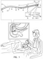
Fig. 1 is a schematic illustration of a guide tube for deployment of a first and second stent in a lumen of a subject, in accordance with some applications of the present invention; -
Fig. 2 is a schematic illustration of apparatus for delivery and deployment of a first and second stent in a lumen of a subject, in accordance with some applications of the present invention; -
Figs. 3A-H are schematic illustrations depicting a general overview of a method for deploying first and second stents in a lumen of a subject, in accordance with some applications of the present disclosure; and -
Fig. 4 is a schematic illustration of an additional configuration of the guide tube for deployment of the first and second stents in the lumen of the subject, in accordance with some applications of the present invention. - The present detailed description begins with a description of a
guide tube 22 which is used to deploy multiple stents in a lumen of the subject, in accordance with some applications of the present invention. - Reference is made to
Figs. 1 and2 . -
Fig. 1 is a schematic illustration ofguide tube 22, in accordance with some applications of the present invention. As shown,guide tube 22 is shape to define aproximal end 30 at aproximal portion 24 ofguide tube 22, and adistal end 32 at adistal portion 26 ofguide tube 22. -
Guide tube 22 is additionally shaped to define a guidewire-engaging portion 122, shown as ahole 40 through awall 36 ofguide tube 22 atdistal portion 26 of the guide tube.Guide tube 22 is further additionally shaped to define aslit 28 extending proximally alongwall 36 ofguide tube 22, fromdistal end 32 of the guide tube. Aproximal end 29 ofslit 28 is located distally toproximal end 30 ofguide tube 22. Additionally,proximal end 29 ofslit 28 is located proximally tohole 40. - Typically,
hole 40 is disposed at an angular offset alpha of 90 - 180 degrees, e.g., 180 degrees, fromslit 28, with respect to a central longitudinal axis A1 of the guide tube. Alternatively, a smaller angle alpha is used (e.g., an angle alpha of approximately 60 degrees is shown inFig. 2 ). As used in the present application, including in the claims, a "central longitudinal axis" of an elongate structure is the set of all centroids of transverse cross-sectional sections of the structure along the structure. Thus the cross-sectional sections are locally perpendicular to the central longitudinal axis, which runs along the structure. (If the structure is circular in cross-section, the centroids correspond with the centers of the circular cross-sectional sections.) The central longitudinal axis of a curved elongate structure is curved, rather than straight. - Typically, a distance D1 between a center of
hole 40 anddistal end 32 ofguide tube 22 is at least 5 mm and/or less than 200 mm e.g., between 5 and 200 mm. - For some applications,
hole 40 is shaped to define an elliptical hole having a major axis W1 which is typically oriented in parallel with longitudinal axis A1 ofguide tube 22. The major axis is typically 1.5 - 4 times longer than a minor axis W2 ofhole 40. For example,hole 40 has major axis W1 having a length of 5 - 10 mm and minor axis W2 having a length of 0.5 - 1.0 mm. -
Slit 28 defines twoslit edges 27 that are parallel to central longitudinal axis A1 ofguide tube 22, typically a distance D2 between a first one of the slit edges and a second one of the slit edges being 0.45 - 0.9 mm. For some applications, whenguide tube 22 is viewed fromdistal end 32 ofguide tube 22, an angle theta of 10-80 degrees, e.g., 20-70 degrees, is formed that is defined by: (a) a first line extending from the central longitudinal axis to a first one of the slit edges, and (b) a second line extending from the central longitudinal axis to a second one of the slit edges. - Reference is still made to
Figs. 1 and2. Fig. 2 is a schematic illustration ofapparatus 20 for delivery and deployment of afirst stent 52 and asecond stent 54 in a lumen of a subject, in accordance with some applications of the present invention. - For some applications,
apparatus 20 comprises guide tube 22 (as described hereinabove with reference toFig. 1 ), and first andsecond stents second stents surround guide tube 22,second stent 54 being disposed proximally tofirst stent 52 and surroundingproximal portion 24 ofguide tube 22.First stent 52 is typically disposed overguide tube 22 such that aproximal end 53 offirst stent 52 is disposed distally toproximal end 29 ofslit 28 ofguide tube 22 while adistal end 55 offirst stent 52 is disposed proximally to hole 40. - For some applications, a
distal end 59 ofsecond stent 54 is disposed proximally toproximal end 29 ofslit 28. For other applications,distal end 59 ofsecond stent 54 is disposed distally toproximal end 29 ofslit 28. -
First stent 52 is slidably advanceable off ofdistal end 32 ofguide tube 22. Additionally,second stent 54, is also shaped and sized to be advanceable overguide tube 22, typically subsequently to advancement offirst stent 52 off ofdistal end 32 ofguide tube 22. - For some applications, first and
second stents slit 28 also has a length L2 of 5 - 15 cm. Typically,slit 28 has a length that is greater than the length offirst stent 52. For some applications,slit 28 has a length that is: (a) greater than a length offirst stent 52, and (b) less than a sum of the length offirst stent 52 and a length ofsecond stent 54. -
Apparatus 20 is typically advanced into a lumen of the subject, andguide tube 22 facilitates placement of first andsecond stents - Reference is now made to
Figs. 3A-H , which depict a general overview of a method for use ofapparatus 20 for deploying first andsecond stents stents apparatus 20 is configured such thatfirst stent 52 is advanced into the lumen of the subject against a guidewire, andsecond stent 54 is advanced into the lumen over the guidewire (i.e., surrounding the guidewire). - Reference is made to
Fig. 3A . In accordance with some applications of the present invention, apparatus 20 (comprisingguide tube 22 and first andsecond stents Fig. 2 ) is used in combination with aguidewire 12 to deploystents guide tube 22 such that following the threading: - (a)
guidewire 12 enters a lumen ofguide tube 22 from a distal-end 32 opening ofguide tube 22, - (b) guidewire 12 passes out of the lumen of
guide tube 22 throughhole 40 ofguide tube 22, - (c)
first stent 52 is constrained from distal motionpast hole 40 ofguide tube 22, due toguidewire 12 being disposed withinhole 40, - (d) guidewire 12 passes into the lumen of
guide tube 22 throughproximal end 29 ofslit 28, and - (e)
first stent 52 is constrained from proximal motion pastproximal end 29 ofslit 28, due toguidewire 12 being disposed withinslit 28. - Following threading of
guidewire 12 throughguide tube 22 as described hereinabove,apparatus 20 is advanced into a body of the subject, e.g., into the small intestine, and intolumen 4 of the common bile duct, as shown inFig. 3A . As shown,first stent 52 is advanced distally overguide tube 22 and against guidewire 12 (i.e., an outer surface offirst stent 52 is disposed against guidewire 12). Due to threading ofguidewire 12 as described hereinabove,stent 52 is advanced distally inlumen 4 while it is constrained from distal motionpast hole 40 ofguide tube 22. Constrained motion of stent 52 (particularly due to guidewire 12 being disposed within hole 40) typically allows forstent 52 to be advanced to a desired deployment site withinlumen 4 in a controlled manner (i.e., inhibiting uncontrolled distal motion ofstent 52, thus allowing the physician to safely perform the implantation at the desired deployment site). - Additionally, due to
guidewire 12 being disposed withinslit 28,first stent 52 is constrained from proximal motion pastproximal end 29 ofslit 28, allowing the physician to advancestent 52 in a controlled manner. - Reference is now made to
Figs. 3B-H . - When
first stent 52 reaches a desired deployment site withinlumen 4, guidewire 12 is removed fromhole 40 ofguide tube 22, by pullingguidewire 12 proximally in the direction indicated byarrow 11, as shown inFig. 3B .Guidewire 12 is then typically advanced distally inlumen 4 as indicated by arrow 13 (Fig. 3C ).Guidewire 12 is thus maintained withinlumen 4 and is not removed fromlumen 4 at this stage. Removal ofguidewire 12 fromhole 40 typically releasesfirst stent 52 and allows forguide tube 22 to be pulled proximally in the direction indicated byarrow 15 untilguide tube 22 is removed fromstent 52, andstent 52 can be deployed in lumen 4 (Fig. 3D ). While pullingguide tube 22 proximally in the direction indicated byarrow 15, guidewire 12 slides throughslit 28 ofguide tube 22 and is consequently centered within a lumen of the guide tube (Fig. 3E ). Centering ofguidewire 12 inguide tube 22 facilitates usingguidewire 12 for deployment ofsecond stent 54 withinlumen 4. Positioning ofguidewire 12 inguide tube 22 usingslit 28 allowssecond stent 54 to be advanced overguidewire 12, whereasfirst stent 52 was advanced against (but not while around)guidewire 12. - As shown in
Fig. 3F , and indicted byarrow 17,second stent 54 is advanced distally inlumen 4 overguide tube 22 and over guidewire 12 (which is the lumen of guide tube 22). As shown inFig. 3G ,second stent 54 continues to be distally advanced in lumen 4 (as indicted by arrows 19) until a desired deployment site is reached alongside first stent 52 (Figs. 3F-G ). Oncesecond stent 54 is deployed alongsidefirst stent 52,guide tube 22 and guidewire 12 are retracted by being pulled in a proximal direction, as indicated byarrow 21 inFig. 3H . - As described in
Figs. 3A-H , use ofapparatus 20 in accordance with some applications of the present disclosure, allows for deployment ofsecond stent 54 subsequently to deployment offirst stent 52, while maintainingguidewire 12 withinlumen 4. Additionally,apparatus 20 allows for deployment ofsecond stent 54 subsequently to deployment offirst stent 52, without removingapparatus 20 from the body of the subject following deployment offirst stent 52 in order to mountsecond stent 54. Notably, first andsecond stents Fig. 2 ) when advanced into the subject's body, to be deployed within the lumen using the techniques described herein. Reference is made toFigs. 2-3H . It is noted that for some applications first andsecond stents - It is additionally noted that stents are described by way of illustration and not limitation. The scope of the present disclosure includes the use of any other drainage tube or tube-like structure configured to relieve stricture of a lumen of a subject.
- Reference is now made to
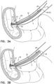
Figs. 3A-4 .Fig. 4 is a schematic illustration of an additional configuration ofguide tube 22 for deployment of first andsecond stents Figs. 1-3H , guidewire-engagingportion 122, embodied ashole 40, is configured to engageguidewire 12 in such a way that it inhibits distal motion offirst stent 52 past guidewire-engagingportion 122 ofguide tube 22, due toguidewire 12 being engaged by portion 122 (e.g., disposed within hole 40). Guidewire-engagingportion 122 is shown inFigs. 1-3H ashole 40 by way of illustration and not limitation. It is noted that guidewire-engagingportion 122 may be shaped to define any other configuration suitable for engagingguidewire 12 in such a manner that will grasp or otherwise holdguidewire 12 and thereby inhibit distal motion offirst stent 52 past guidewire-engagingportion 122 whenstent 52 is advanced distally againstguidewire 12. It is noted that the techniques described herein with reference toFigs. 3A-H apply to guidewire-engagingportion 122 as shown inFig. 4 as well. - As shown in
Fig. 4 , for some applications, edges 27 ofslit 28 are shaped to define guidewire-engagingportion 122. Typically, distance D2 between a first one of the slit edges and a second one of the slit edges is 0.45 - 0.9 mm. However, at guidewire-engagingportion 122, a distance D3 between slit edges 27 is smaller than distance D2, such that, for example, D2 is 2 - 5 times larger than D3. Typically, distance D3 between slit edges 27 is 0.09 mm - 0.45 mm, e.g., greater than 0.15 mm and/or less than 0.4 mm. Typically, guidewire-engagingportion 122 shown inFig. 4 has a length that is 5 -10 times longer than D3, e.g., 0.45 mm - 4.5 mm, e.g., greater than 1 mm and/or less than 3.5 mm. As shown inFig. 4 , guidewire 12 is typically engaged by, and locked into, the narrowed area inslit 28 which defines guidewire-engagingportion 122. Engagingguidewire 12 by guidewire-engagingportion 122 typically allows forfirst stent 52 to be advanced to a desired deployment site within the lumen of the subject in a controlled manner (i.e., inhibiting uncontrolled distal motion ofstent 52 whenstent 52 is advanced distally againstguidewire 12, thus allowing the physician to safely perform the implantation at the desired deployment site). - In other words, when
guidewire 12 is disposed (i) at least in part in a lumen ofguide tube 22, (ii) passing through an opening atdistal end 32 ofguide tube 22, (iii) passing through guidewire-engagingportion 122 ofguide tube 22, and (iv) passing throughproximal end 29 ofslit 28,first stent 52 is (i) constrained from distal motion past guidewire-engagingportion 122, and (ii) constrained from proximal motion pastproximal end 29 of theslit 28. Additionally, whenguidewire 12 is disposed (i) at least in part in a lumen ofguide tube 22, (ii) passing through an opening atdistal end 32 ofguide tube 22, (iii) passing through guidewire-engagingportion 122 ofguide tube 22, and (iv) passing throughproximal end 29 ofslit 28,second stent 54 is constrained from distal motion past the proximal end of the slit. - Once
first stent 52 is in a desired deployment site in the lumen of the subject, guidewire 12 is released from guidewire-engagingportion 122 by pullingguidewire 12. Removal ofguidewire 12 from guidewire-engagingportion 122 typically releasesfirst stent 52 and allows guidetube 22 to be pulled proximally in the direction indicated by arrow 15 (as shown inFig. 3D ) untilguide tube 22 is removed fromstent 52, andstent 52 can be deployed in the lumen of the subject. - It is noted that for other applications, guidewire-engaging
portion 122 may comprise a clip or any other suitable apparatus for engagement ofguidewire 12. - Reference is made to
Figs. 1-4 . It is noted that for someapplications apparatus 20 is configured to deploy more than two stents, e.g., three or four stents, in the lumen of the subject (configuration not shown). Typically for such applications, guidetube 22 is shaped to define a second guidewire-engaging portion e.g., asecond hole 40, onproximal portion 24 oftube 22. - Reference is still made to
Figs. 1-4 . It is noted thatapparatus 20 is described with reference tolumen 4 of a common bile duct by way of illustration and not limitation. The scope of the present disclosure includes use ofapparatus 20 in any suitable lumen to deploy multiple stents in the lumen. For example, techniques and apparatus described herein may be used in a urethra, and/or in a ureter, and/or in a pancreatic duct, and/or in an esophagus, and/or in a trachea of the subject. Additionally or alternatively, techniques and apparatus described herein may be used to deploy two or more prostatic stents. - It will be appreciated by persons skilled in the art that the present invention is not limited to what has been particularly shown and described hereinabove. Rather, the scope of the present invention includes both combinations and subcombinations of the various features described hereinabove, as well as variations and modifications thereof that are not in the prior art, which would occur to persons skilled in the art upon reading the foregoing description. through the proximal end of the slit, and the first stent is (i) constrained from distal motion past the hole when the guidewire is disposed within the hole, and (ii) constrained from proximal motion past the proximal end of the slit when the guidewire is disposed within the slit.
- For some applications, the first stent is slidably advanceable off the distal end of the guide tube when the guidewire is not disposed within the hole.
- For some applications, the hole is disposed at an angular offset of 90 - 180 degrees from the slit, with respect to a central longitudinal axis of the guide tube.
- For some applications, the hole is disposed at an angular offset of 180 degrees from the slit, with respect to the central longitudinal axis of the guide tube.
- For some applications, a distance between a center of the hole and the distal end of the guide tube is at least 5 mm.
- For some applications, a distance between a center of the hole and the distal end of the guide tube is less than 200 mm.
- For some applications, the first stent has a length of 5 - 15 cm.
- For some applications, the slit has a length that is greater than the length of the first stent.
- For some applications, the second stent has a length of 5 - 15 cm.
- For some applications, the slit has a length of 5 - 15 cm.
- For some applications, the slit has a length that is: (a) greater than a length of the first stent, and (b) less than a sum of the length of the first stent and a length of the second stent.
- For some applications, the hole is shaped to define an elliptical hole.
- For some applications, the major axis of the elliptical hole is oriented in parallel with a longitudinal axis of the guide tube.
- For some applications, the elliptical hole has a major axis having a length of 5 -10 mm and a minor axis having a length of 0.5 - 1.0 mm.
- For some applications, the major axis is 1.5 - 4 times longer than the minor axis.
- For some applications, the slit defines two slit edges that are parallel to a central longitudinal axis of the guide tube, a distance between a first one of the slit edges and a second one of the slit edges being 0.45 - 0.9 mm.
- For some applications, the slit defines two slit edges that are parallel to a central longitudinal axis of the guide tube, such that, were the guide tube to be viewed from the distal end of the guide tube, an angle of 10-80 degrees is formed that is defined by:
- (a) a first line extending from the central longitudinal axis to a first one of the slit edges, and
- (b) a second line extending from the central longitudinal axis to a second one of the slit edges.
- For some applications, the angle is 20-70 degrees.
- For some applications, a distal end of the second stent is disposed proximally to the proximal end of the slit.
- For some applications, a distal end of the second stent is disposed distally to the proximal end of the slit.
- For some applications, the first stent includes a self-expandable stent.
- For some applications, the second stent includes a self-expandable stent.
- There is further provided in accordance with some applications of the present disclosure, a method including:
- providing apparatus including:
- a guide tube shaped to define (a) a hole through a wall of the guide tube at a distal portion of the guide tube, and (b) a slit extending proximally along the wall of the guide tube, from a distal end of the guide tube, a proximal end of the slit being located distally to a proximal end of the guide tube,
- a first stent surrounding the distal portion of the guide tube, and
- a second stent, proximal to the first stent, surrounding a proximal portion of the guide tube;
- threading a guidewire through the guide tube, such that, following the threading:
- (a) the guidewire enters a lumen of the guide tube from a distal-end opening of the guide tube,
- (b) the guidewire passes out of the lumen of the guide tube through the hole of the guide tube,
- (c) the first stent is constrained from distal motion past the hole of the guide tube, due to the guidewire being disposed within the hole,
- (d) the guidewire passes into the lumen of the guide tube through the slit, and
- (e) the first stent is constrained from proximal motion past the proximal end of the slit, due to the guidewire being disposed within the slit.
- For some applications the method further includes:
- advancing the apparatus to a desired location in a lumen of a subject while the guidewire is threaded through the guide tube and an outer surface of the first stent is disposed against the guidewire;
- subsequently to the advancing of the apparatus, removing the guidewire from the hole;
- subsequently to the removing, advancing the first stent along the guide tube and off of the distal end of the guide tube into the lumen until the first stent is deployed in the desired location in the lumen of the subject;
- subsequently to advancing the first stent off of the distal end of the guide tube, advancing the second stent along the guide tube and over the guidewire in the lumen of the subject; and
- subsequently to advancing the first stent, advancing the second stent off of the distal end of the guide tube, and placing the second stent alongside the first stent.
- There is further provided in accordance with some applications of the present disclosure, a method including:
- providing apparatus including:
- a guide tube shaped to define (a) a guidewire-engaging portion at a distal portion of the guide tube, and (b) a slit extending proximally along a wall of the guide tube, from a distal end of the guide tube, a proximal end of the slit being located distally to a proximal end of the guide tube,
- a first stent surrounding the distal portion of the guide tube, and
- a second stent, proximal to the first stent, surrounding a proximal portion of the guide tube;
- threading a guidewire through the guide tube, such that, following the threading:
- (a) the guidewire enters a lumen of the guide tube from a distal-end opening of the guide tube,
- (b) the guidewire passes through the guidewire-engaging portion of the guide tube,
- (c) the first stent is constrained from distal motion past the guidewire-engaging portion of the guide tube, due to the guidewire passing through the guidewire-engaging portion,
- (d) the guidewire passes into the lumen of the guide tube through the slit, and
- (e) the first stent is constrained from proximal motion past the proximal end of the slit, due to the guidewire being disposed within the slit.
- For some applications the method further includes:
- advancing the apparatus to a desired location in a lumen of a subject while the guidewire is threaded through the guide tube and an outer surface of the first stent is disposed against the guidewire;
- subsequently to the advancing of the apparatus, removing the guidewire from the guidewire-engaging portion;
- subsequently to the removing, advancing the first stent along the guide tube and off of the distal end of the guide tube into the lumen until the first stent is deployed in the desired location in the lumen of the subject;
- subsequently to advancing the first stent off of the distal end of the guide tube, advancing the second stent along the guide tube and over the guidewire in the lumen of the subject; and
- subsequently to advancing the first stent, advancing the second stent off of the distal end of the guide tube, and placing the second stent alongside the first stent.
- There is further provided in accordance with some applications of the present disclosure, a method including:
- providing (i) a first stent and (ii) a second stent proximal to the first stent;
- advancing the first stent against a guidewire into a lumen of a subject;
- deploying the first stent in the lumen of the subject;
- while maintaining the guidewire in the lumen of the subject subsequently to deployment of the first stent, advancing the second stent over the guidewire into the lumen of the subject; and
- deploying the second stent in the lumen alongside the first stent.
- There is further provided in accordance with some applications of the present invention, apparatus including:
- a first stent configured to be advanced into a lumen of a subject against the guidewire; and
- a second stent proximal to the first stent, and configured to be advanced into the lumen of the subject over the guidewire.
- For some applications, the apparatus further includes the guidewire.
- For some applications, an outer surface of the first stent is disposed against the guidewire and the second stent surrounds the guidewire.
- For some applications, the apparatus further includes a third stent, proximal to the second stent and configured to be advanced into the lumen of the subject over the guidewire.
- For some applications, the apparatus further includes a fourth stent, proximal to the third stent and configured to be advanced into the lumen of the subject over the guidewire.
- The present invention will be more fully understood from the following detailed description of applications thereof, taken together with the drawings, in which:
-
-
Fig. 1 is a schematic illustration of a guide tube for deployment of a first and second stent in a lumen of a subject, in accordance with some applications of the present invention; -
Fig. 2 is a schematic illustration of apparatus for delivery and deployment of a first and second stent in a lumen of a subject, in accordance with some applications of the present invention; -
Figs. 3A-H are schematic illustrations depicting a general overview of a method for deploying first and second stents in a lumen of a subject, in accordance with some applications of the present disclosure; and -
Fig. 4 is a schematic illustration of an additional configuration of the guide tube for deployment of the first and second stents in the lumen of the subject, in accordance with some applications of the present invention. - The present detailed description begins with a description of a
guide tube 22 which is used to deploy multiple stents in a lumen of the subject, in accordance with some applications of the present invention. - Reference is made to
Figs. 1 and2 . -
Fig. 1 is a schematic illustration ofguide tube 22, in accordance with some applications of the present invention. As shown, guidetube 22 is shape to define aproximal end 30 at aproximal portion 24 ofguide tube 22, and adistal end 32 at adistal portion 26 ofguide tube 22. -
Guide tube 22 is additionally shaped to define a guidewire-engagingportion 122, shown as ahole 40 through awall 36 ofguide tube 22 atdistal portion 26 of the guide tube.Guide tube 22 is further additionally shaped to define aslit 28 extending proximally alongwall 36 ofguide tube 22, fromdistal end 32 of the guide tube. Aproximal end 29 ofslit 28 is located distally toproximal end 30 ofguide tube 22. Additionally,proximal end 29 ofslit 28 is located proximally tohole 40. - Typically,
hole 40 is disposed at an angular offset alpha of 90 - 180 degrees, e.g., 180 degrees, fromslit 28, with respect to a central longitudinal axis A1 of the guide tube. Alternatively, a smaller angle alpha is used (e.g., an angle alpha of approximately 60 degrees is shown inFig. 2 ). As used in the present application, including in the claims, a "central longitudinal axis" of an elongate structure is the set of all centroids of transverse cross-sectional sections of the structure along the structure. Thus the cross-sectional sections are locally perpendicular to the central longitudinal axis, which runs along the structure. (If the structure is circular in cross-section, the centroids correspond with the centers of the circular cross-sectional sections.) The central longitudinal axis of a curved elongate structure is curved, rather than straight. - Typically, a distance D1 between a center of
hole 40 anddistal end 32 ofguide tube 22 is at least 5 mm and/or less than 200 mm e.g., between 5 and 200 mm. - For some applications,
hole 40 is shaped to define an elliptical hole having a major axis W1 which is typically oriented in parallel with longitudinal axis A1 ofguide tube 22. The major axis is typically 1.5 - 4 times longer than a minor axis W2 ofhole 40. For example,hole 40 has major axis W1 having a length of 5 - 10 mm and minor axis W2 having a length of 0.5 - 1.0 mm. -
Slit 28 defines two slitedges 27 that are parallel to central longitudinal axis A1 ofguide tube 22, typically a distance D2 between a first one of the slit edges and a second one of the slit edges being 0.45 - 0.9 mm. For some applications, whenguide tube 22 is viewed fromdistal end 32 ofguide tube 22, an angle theta of 10-80 degrees, e.g., 20-70 degrees, is formed that is defined by: (a) a first line extending from the central longitudinal axis to a first one of the slit edges, and (b) a second line extending from the central longitudinal axis to a second one of the slit edges. - Reference is still made to
Figs. 1 and2. Fig. 2 is a schematic illustration ofapparatus 20 for delivery and deployment of afirst stent 52 and asecond stent 54 in a lumen of a subject, in accordance with some applications of the present invention. - For some applications,
apparatus 20 comprises guide tube 22 (as described hereinabove with reference toFig. 1 ), and first andsecond stents second stents surround guide tube 22,second stent 54 being disposed proximally tofirst stent 52 and surroundingproximal portion 24 ofguide tube 22.First stent 52 is typically disposed overguide tube 22 such that aproximal end 53 offirst stent 52 is disposed distally toproximal end 29 ofslit 28 ofguide tube 22 while adistal end 55 offirst stent 52 is disposed proximally tohole 40. - For some applications, a
distal end 59 ofsecond stent 54 is disposed proximally toproximal end 29 ofslit 28. For other applications,distal end 59 ofsecond stent 54 is disposed distally toproximal end 29 ofslit 28. -
First stent 52 is slidably advanceable off ofdistal end 32 ofguide tube 22. Additionally,second stent 54, is also shaped and sized to be advanceable overguide tube 22, typically subsequently to advancement offirst stent 52 off ofdistal end 32 ofguide tube 22. - For some applications, first and
second stents first stent 52. For some applications, slit 28 has a length that is: (a) greater than a length offirst stent 52, and (b) less than a sum of the length offirst stent 52 and a length ofsecond stent 54. -
Apparatus 20 is typically advanced into a lumen of the subject, and guidetube 22 facilitates placement of first andsecond stents - Reference is now made to
Figs. 3A-H , which depict a general overview of a method for use ofapparatus 20 for deploying first andsecond stents stents apparatus 20 is configured such thatfirst stent 52 is advanced into the lumen of the subject against a guidewire, andsecond stent 54 is advanced into the lumen over the guidewire (i.e., surrounding the guidewire). - Reference is made to
Fig. 3A . In accordance with some applications of the present invention, apparatus 20 (comprisingguide tube 22 and first andsecond stents Fig. 2 ) is used in combination with aguidewire 12 to deploystents Guidewire 12 is typically threaded throughguide tube 22 such that following the threading: - (a)
guidewire 12 enters a lumen ofguide tube 22 from a distal-end 32 opening ofguide tube 22, - (b) guidewire 12 passes out of the lumen of
guide tube 22 throughhole 40 ofguide tube 22, - (c)
first stent 52 is constrained from distal motionpast hole 40 ofguide tube 22, due toguidewire 12 being disposed withinhole 40, - (d) guidewire 12 passes into the lumen of
guide tube 22 throughproximal end 29 ofslit 28, and - (e)
first stent 52 is constrained from proximal motion pastproximal end 29 ofslit 28, due toguidewire 12 being disposed withinslit 28. - Following threading of
guidewire 12 throughguide tube 22 as described hereinabove,apparatus 20 is advanced into a body of the subject, e.g., into the small intestine, and intolumen 4 of the common bile duct, as shown inFig. 3A . As shown,first stent 52 is advanced distally overguide tube 22 and against guidewire 12 (i.e., an outer surface offirst stent 52 is disposed against guidewire 12). Due to threading ofguidewire 12 as described hereinabove,stent 52 is advanced distally inlumen 4 while it is constrained from distal motionpast hole 40 ofguide tube 22. Constrained motion of stent 52 (particularly due to guidewire 12 being disposed within hole 40) typically allows forstent 52 to be advanced to a desired deployment site withinlumen 4 in a controlled manner (i.e., inhibiting uncontrolled distal motion ofstent 52, thus allowing the physician to safely perform the implantation at the desired deployment site). - Additionally, due to
guidewire 12 being disposed withinslit 28,first stent 52 is constrained from proximal motion pastproximal end 29 ofslit 28, allowing the physician to advancestent 52 in a controlled manner. - Reference is now made to
Figs. 3B-H . - When
first stent 52 reaches a desired deployment site withinlumen 4, guidewire 12 is removed fromhole 40 ofguide tube 22, by pullingguidewire 12 proximally in the direction indicated byarrow 11, as shown inFig. 3B .Guidewire 12 is then typically advanced distally inlumen 4 as indicated by arrow 13 (Fig. 3C ).Guidewire 12 is thus maintained withinlumen 4 and is not removed fromlumen 4 at this stage. Removal ofguidewire 12 fromhole 40 typically releasesfirst stent 52 and allows forguide tube 22 to be pulled proximally in the direction indicated byarrow 15 untilguide tube 22 is removed fromstent 52, andstent 52 can be deployed in lumen 4 (Fig. 3D ). While pullingguide tube 22 proximally in the direction indicated byarrow 15, guidewire 12 slides throughslit 28 ofguide tube 22 and is consequently centered within a lumen of the guide tube (Fig. 3E ). Centering ofguidewire 12 inguide tube 22 facilitates usingguidewire 12 for deployment ofsecond stent 54 withinlumen 4. Positioning ofguidewire 12 inguide tube 22 usingslit 28 allowssecond stent 54 to be advanced overguidewire 12, whereasfirst stent 52 was advanced against (but not while around)guidewire 12. - As shown in
Fig. 3F , and indicted byarrow 17,second stent 54 is advanced distally inlumen 4 overguide tube 22 and over guidewire 12 (which is the lumen of guide tube 22). As shown inFig. 3G ,second stent 54 continues to be distally advanced in lumen 4 (as indicted by arrows 19) until a desired deployment site is reached alongside first stent 52 (Figs. 3F-G ). Oncesecond stent 54 is deployed alongsidefirst stent 52,guide tube 22 and guidewire 12 are retracted by being pulled in a proximal direction, as indicated byarrow 21 inFig. 3H . - As described in
Figs. 3A-H , use ofapparatus 20 in accordance with some applications of the present disclosure, allows for deployment ofsecond stent 54 subsequently to deployment offirst stent 52, while maintainingguidewire 12 withinlumen 4. Additionally,apparatus 20 allows for deployment ofsecond stent 54 subsequently to deployment offirst stent 52, without removingapparatus 20 from the body of the subject following deployment offirst stent 52 in order to mountsecond stent 54. Notably, first andsecond stents Fig. 2 ) when advanced into the subject's body, to be deployed within the lumen using the techniques described herein. Reference is made toFigs. 2-3H . It is noted that for some applications first andsecond stents - It is additionally noted that stents are described by way of illustration and not limitation. The scope of the present disclosure includes the use of any other drainage tube or tube-like structure configured to relieve stricture of a lumen of a subject.
- Reference is now made to
Figs. 3A-4 .Fig. 4 is a schematic illustration of an additional configuration ofguide tube 22 for deployment of first andsecond stents Figs. 1-3H , guidewire-engagingportion 122, embodied ashole 40, is configured to engageguidewire 12 in such a way that it inhibits distal motion offirst stent 52 past guidewire-engagingportion 122 ofguide tube 22, due toguidewire 12 being engaged by portion 122 (e.g., disposed within hole 40). Guidewire-engagingportion 122 is shown inFigs. 1-3H ashole 40 by way of illustration and not limitation. It is noted that guidewire-engagingportion 122 may be shaped to define any other configuration suitable for engagingguidewire 12 in such a manner that will grasp or otherwise holdguidewire 12 and thereby inhibit distal motion offirst stent 52 past guidewire-engagingportion 122 whenstent 52 is advanced distally againstguidewire 12. It is noted that the techniques described herein with reference toFigs. 3A-H apply to guidewire-engagingportion 122 as shown inFig. 4 as well. - As shown in
Fig. 4 , for some applications, edges 27 ofslit 28 are shaped to define guidewire-engagingportion 122. Typically, distance D2 between a first one of the slit edges and a second one of the slit edges is 0.45 - 0.9 mm. However, at guidewire-engagingportion 122, a distance D3 between slit edges 27 is smaller than distance D2, such that, for example, D2 is 2 - 5 times larger than D3. Typically, distance D3 between slit edges 27 is 0.09 mm - 0.45 mm, e.g., greater than 0.15 mm and/or less than 0.4 mm. Typically, guidewire-engagingportion 122 shown inFig. 4 has a length that is 5 - 10 times longer than D3, e.g., 0.45 mm - 4.5 mm, e.g., greater than 1 mm and/or less than 3.5 mm. As shown inFig. 4 , guidewire 12 is typically engaged by, and locked into, the narrowed area inslit 28 which defines guidewire-engagingportion 122. Engagingguidewire 12 by guidewire-engagingportion 122 typically allows forfirst stent 52 to be advanced to a desired deployment site within the lumen of the subject in a controlled manner (i.e., inhibiting uncontrolled distal motion ofstent 52 whenstent 52 is advanced distally againstguidewire 12, thus allowing the physician to safely perform the implantation at the desired deployment site). - In other words, when
guidewire 12 is disposed (i) at least in part in a lumen ofguide tube 22, (ii) passing through an opening atdistal end 32 ofguide tube 22, (iii) passing through guidewire-engagingportion 122 ofguide tube 22, and (iv) passing throughproximal end 29 ofslit 28,first stent 52 is (i) constrained from distal motion past guidewire-engagingportion 122, and (ii) constrained from proximal motion pastproximal end 29 of theslit 28. Additionally, whenguidewire 12 is disposed (i) at least in part in a lumen ofguide tube 22, (ii) passing through an opening atdistal end 32 ofguide tube 22, (iii) passing through guidewire-engagingportion 122 ofguide tube 22, and (iv) passing throughproximal end 29 ofslit 28,second stent 54 is constrained from distal motion past the proximal end of the slit. - Once
first stent 52 is in a desired deployment site in the lumen of the subject, guidewire 12 is released from guidewire-engagingportion 122 by pullingguidewire 12. Removal ofguidewire 12 from guidewire-engagingportion 122 typically releasesfirst stent 52 and allows guidetube 22 to be pulled proximally in the direction indicated by arrow 15 (as shown inFig. 3D ) untilguide tube 22 is removed fromstent 52, andstent 52 can be deployed in the lumen of the subj ect. - It is noted that for other applications, guidewire-engaging
portion 122 may comprise a clip or any other suitable apparatus for engagement ofguidewire 12. - Reference is made to
Figs. 1-4 . It is noted that for someapplications apparatus 20 is configured to deploy more than two stents, e.g., three or four stents, in the lumen of the subject (configuration not shown). Typically for such applications, guidetube 22 is shaped to define a second guidewire-engaging portion e.g., asecond hole 40, onproximal portion 24 oftube 22. - Reference is still made to
Figs. 1-4 . It is noted thatapparatus 20 is described with reference tolumen 4 of a common bile duct by way of illustration and not limitation. The scope of the present disclosure includes use ofapparatus 20 in any suitable lumen to deploy multiple stents in the lumen. For example, techniques and apparatus described herein may be used in a urethra, and/or in a ureter, and/or in a pancreatic duct, and/or in an esophagus, and/or in a trachea of the subject. Additionally or alternatively, techniques and apparatus described herein may be used to deploy two or more prostatic stents. - It will be appreciated by persons skilled in the art that the present invention is not limited to what has been particularly shown and described hereinabove. Rather, the scope of the present invention includes both combinations and subcombinations of the various features described hereinabove, as well as variations and modifications thereof that are not in the prior art, which would occur to persons skilled in the art upon reading the foregoing description. hereinabove but it is just limited by the claims.
Claims (5)
- Apparatus for delivery of stents, comprising:a guidewire (12);a first stent (52) (i) having an outer surface disposed against the guidewire (12) and (ii) configured to be advanced into a lumen of a subject while the outer surface is disposed against the guidewire (12);a second stent (54) proximal to the first stent (52), surrounding the guidewire (12), and configured to be advanced into the lumen of the subject over the guidewire (12) and placed alongside the first stent subsequent to advancement of the first stent (52) off a distal end (32) of a guide tube (22); andthe guide tube (22) disposed within the first and second stents (52,54) and advanceable therewith, the guide tube (22) shaped to define (a) a guidewire-engaging portion (122), and (b) a slit (28) extending proximally along a wall (36) of the guide tube (22), from thedistal end (32) of the guide tube (22), a proximal end (29) of the slit (28) being located distally to a proximal end (30) of the guide tube (22), the guidewire-engaging portion (122) comprising one of a narrowed area in the slit (28) and a hole (40) through the wall (36) of the guide tube (22),wherein the guidewire (12) (i) enters a lumen of the guide tube (22) from a distal-end opening of the guide tube (22), (ii) passes out of the lumen of the guide tube (22) through the guidewire-engaging portion (122) of the guide tube (22), and (iii) passes into the lumen of the guide tube (22) through the proximal end (29) of the slit (28), and wherein the first stent (52) is (i) constrained from distal motion past the guidewire-engaging portion (122) when the guidewire (12) is disposed within the guidewire-engaging portion (122), and (ii) constrained from proximal motion past the proximal end (29) of the slit (28) when the guidewire (12) is disposed within the slit (28).
- The apparatus of claim 1, wherein the guidewire-engaging portion (122) comprises a narrowed area in the slit (28).
- The apparatus of claim 1, wherein the guidewire-engaging portion (122) comprises a hole (40) through the wall (36) of the guide tube (22)
- The apparatus according to claim 1, further comprising a third stent, proximal to the second stent (54) and configured to be advanced into the lumen of the subject over the guidewire (12).
- The apparatus according to claim 4, further comprising a fourth stent, proximal to the third stent and configured to be advanced into the lumen of the subject over the guidewire (12).
Applications Claiming Priority (2)
| Application Number | Priority Date | Filing Date | Title |
|---|---|---|---|
| GBGB1522683.0A GB201522683D0 (en) | 2015-12-22 | 2015-12-22 | Deployment of multiple biliary stents |
| PCT/IL2016/051368 WO2017109783A1 (en) | 2015-12-22 | 2016-12-22 | Deployment of multiple biliary stents |
Publications (3)
| Publication Number | Publication Date |
|---|---|
| EP3393406A1 EP3393406A1 (en) | 2018-10-31 |
| EP3393406B1 true EP3393406B1 (en) | 2023-12-13 |
| EP3393406C0 EP3393406C0 (en) | 2023-12-13 |
Family
ID=55311464
Family Applications (1)
| Application Number | Title | Priority Date | Filing Date |
|---|---|---|---|
| EP16826475.2A Active EP3393406B1 (en) | 2015-12-22 | 2016-12-22 | Deployment of multiple biliary stents |
Country Status (6)
| Country | Link |
|---|---|
| US (2) | US11154411B2 (en) |
| EP (1) | EP3393406B1 (en) |
| CN (2) | CN108366865B (en) |
| ES (1) | ES2965712T3 (en) |
| GB (1) | GB201522683D0 (en) |
| WO (1) | WO2017109783A1 (en) |
Families Citing this family (3)
| Publication number | Priority date | Publication date | Assignee | Title |
|---|---|---|---|---|
| WO2020003316A1 (en) | 2018-06-28 | 2020-01-02 | Endo Gi Medical Ltd. | Deployment of multiple biliary stents |
| AU2020201370B2 (en) * | 2018-06-28 | 2020-08-20 | Endo Gi Medical Ltd. | Deployment of multiple biliary stents |
| US11744694B2 (en) | 2020-01-01 | 2023-09-05 | Endo Gi Medical Ltd. | Methods and assemblies for deploying biliary stents |
Family Cites Families (19)
| Publication number | Priority date | Publication date | Assignee | Title |
|---|---|---|---|---|
| US5669924A (en) | 1995-10-26 | 1997-09-23 | Shaknovich; Alexander | Y-shuttle stent assembly for bifurcating vessels and method of using the same |
| US6682536B2 (en) * | 2000-03-22 | 2004-01-27 | Advanced Stent Technologies, Inc. | Guidewire introducer sheath |
| US6299595B1 (en) | 1999-12-17 | 2001-10-09 | Advanced Cardiovascular Systems, Inc. | Catheters having rapid-exchange and over-the-wire operating modes |
| US8211087B2 (en) | 2003-07-31 | 2012-07-03 | Cook Medical Technologies Llc | Distal wire stop |
| US20150011834A1 (en) | 2003-07-31 | 2015-01-08 | Cook Medical Technologies Llc | System and method for introducing multiple medical devices |
| EP1653884B1 (en) * | 2003-07-31 | 2008-06-25 | Wilson-Cook Medical Inc. | System for introducing a prosthesis |
| US20050125050A1 (en) | 2003-12-04 | 2005-06-09 | Wilson Cook Medical Incorporated | Biliary stent introducer system |
| US7323006B2 (en) * | 2004-03-30 | 2008-01-29 | Xtent, Inc. | Rapid exchange interventional devices and methods |
| WO2005096994A1 (en) * | 2004-03-31 | 2005-10-20 | Wilson-Cook Medical Inc. | Stent introducer system |
| US9510962B2 (en) | 2006-06-16 | 2016-12-06 | Olympus Corporation | Stent delivery system |
| US7691125B2 (en) | 2007-10-04 | 2010-04-06 | Wilson-Cook Medical Inc. | System and method for forming a stent of a desired length at an endoluminal site |
| US7963987B2 (en) | 2007-12-28 | 2011-06-21 | Cook Medical Technologies Llc | Sequential implant delivery system |
| CA2721950A1 (en) * | 2008-04-25 | 2009-10-29 | Nellix, Inc. | Stent graft delivery system |
| BRPI1012599A2 (en) * | 2009-03-13 | 2016-03-22 | Bolton Medical Inc | system and method for placing an endoluminal prosthesis in a surgical site |
| CN102869296B (en) | 2009-12-18 | 2015-09-09 | 库克医学技术有限责任公司 | Endoscope sheath |
| US9095466B2 (en) * | 2010-11-16 | 2015-08-04 | W. L. Gore & Associates, Inc. | Apposition fiber for use in endoluminal deployment of expandable devices in tortuous anatomies |
| US20130030416A1 (en) * | 2011-07-29 | 2013-01-31 | Boston Scientific Scimed, Inc. | Rapid Exchange Stent Delivery System |
| US9402755B2 (en) * | 2012-03-13 | 2016-08-02 | W. L. Gore & Associates, Inc. | Sleeve retraction system |
| US8955520B2 (en) | 2012-07-19 | 2015-02-17 | Cook Medical Technologies Llc | Method of placing multiple biliary stents without re-intervention, and device for same |
-
2015
- 2015-12-22 GB GBGB1522683.0A patent/GB201522683D0/en not_active Ceased
-
2016
- 2016-12-22 US US16/064,843 patent/US11154411B2/en active Active
- 2016-12-22 CN CN201680074463.XA patent/CN108366865B/en active Active
- 2016-12-22 ES ES16826475T patent/ES2965712T3/en active Active
- 2016-12-22 EP EP16826475.2A patent/EP3393406B1/en active Active
- 2016-12-22 WO PCT/IL2016/051368 patent/WO2017109783A1/en active Application Filing
- 2016-12-22 CN CN202110661858.2A patent/CN113367833A/en active Pending
-
2021
- 2021-09-28 US US17/449,253 patent/US20220008234A1/en active Pending
Also Published As
| Publication number | Publication date |
|---|---|
| CN113367833A (en) | 2021-09-10 |
| ES2965712T3 (en) | 2024-04-16 |
| EP3393406C0 (en) | 2023-12-13 |
| EP3393406A1 (en) | 2018-10-31 |
| US20220008234A1 (en) | 2022-01-13 |
| CN108366865A (en) | 2018-08-03 |
| GB201522683D0 (en) | 2016-02-03 |
| CN108366865B (en) | 2021-06-25 |
| US20190000652A1 (en) | 2019-01-03 |
| US11154411B2 (en) | 2021-10-26 |
| WO2017109783A1 (en) | 2017-06-29 |
Similar Documents
| Publication | Publication Date | Title |
|---|---|---|
| US20220008234A1 (en) | Deployment of multiple biliary stents | |
| US10195063B2 (en) | Endoprosthesis having aligned legs for ease of cannulation | |
| US10058442B2 (en) | Endoprosthesis delivery system | |
| US20110224775A1 (en) | Stent Geometry | |
| US20160101267A1 (en) | Anchoring Device and Methods for Use | |
| AU2020201370B2 (en) | Deployment of multiple biliary stents | |
| US20150297875A1 (en) | Vascular dilator systems, kits, and methods | |
| US20210259867A1 (en) | Deployment of multiple biliary stents | |
| EP2874567B1 (en) | Anti-migration biliary stent | |
| WO2020003316A1 (en) | Deployment of multiple biliary stents | |
| US11744694B2 (en) | Methods and assemblies for deploying biliary stents | |
| EP3285700B1 (en) | Systems for stent delivery | |
| US8257422B2 (en) | Over-the-wire detachment mechanism | |
| US20140336464A1 (en) | Expansion devices and methods of use thereof | |
| US20240024138A1 (en) | Methods and assemblies for deploying biliary stents | |
| JP7216578B2 (en) | stent delivery system | |
| US20230032980A1 (en) | Multistage expandable loading dilator | |
| EP1772121A1 (en) | Catheter for treating an intimal dissection after stent implantation |
Legal Events
| Date | Code | Title | Description |
|---|---|---|---|
| STAA | Information on the status of an ep patent application or granted ep patent |
Free format text: STATUS: UNKNOWN |
|
| STAA | Information on the status of an ep patent application or granted ep patent |
Free format text: STATUS: THE INTERNATIONAL PUBLICATION HAS BEEN MADE |
|
| PUAI | Public reference made under article 153(3) epc to a published international application that has entered the european phase |
Free format text: ORIGINAL CODE: 0009012 |
|
| STAA | Information on the status of an ep patent application or granted ep patent |
Free format text: STATUS: REQUEST FOR EXAMINATION WAS MADE |
|
| 17P | Request for examination filed |
Effective date: 20180718 |
|
| AK | Designated contracting states |
Kind code of ref document: A1 Designated state(s): AL AT BE BG CH CY CZ DE DK EE ES FI FR GB GR HR HU IE IS IT LI LT LU LV MC MK MT NL NO PL PT RO RS SE SI SK SM TR |
|
| AX | Request for extension of the european patent |
Extension state: BA ME |
|
| DAV | Request for validation of the european patent (deleted) | ||
| DAX | Request for extension of the european patent (deleted) | ||
| STAA | Information on the status of an ep patent application or granted ep patent |
Free format text: STATUS: EXAMINATION IS IN PROGRESS |
|
| 17Q | First examination report despatched |
Effective date: 20201217 |
|
| STAA | Information on the status of an ep patent application or granted ep patent |
Free format text: STATUS: EXAMINATION IS IN PROGRESS |
|
| GRAP | Despatch of communication of intention to grant a patent |
Free format text: ORIGINAL CODE: EPIDOSNIGR1 |
|
| STAA | Information on the status of an ep patent application or granted ep patent |
Free format text: STATUS: GRANT OF PATENT IS INTENDED |
|
| INTG | Intention to grant announced |
Effective date: 20230630 |
|
| GRAS | Grant fee paid |
Free format text: ORIGINAL CODE: EPIDOSNIGR3 |
|
| GRAA | (expected) grant |
Free format text: ORIGINAL CODE: 0009210 |
|
| STAA | Information on the status of an ep patent application or granted ep patent |
Free format text: STATUS: THE PATENT HAS BEEN GRANTED |
|
| AK | Designated contracting states |
Kind code of ref document: B1 Designated state(s): AL AT BE BG CH CY CZ DE DK EE ES FI FR GB GR HR HU IE IS IT LI LT LU LV MC MK MT NL NO PL PT RO RS SE SI SK SM TR |
|
| REG | Reference to a national code |
Ref country code: GB Ref legal event code: FG4D |
|
| REG | Reference to a national code |
Ref country code: CH Ref legal event code: EP |
|
| REG | Reference to a national code |
Ref country code: DE Ref legal event code: R096 Ref document number: 602016084729 Country of ref document: DE |
|
| REG | Reference to a national code |
Ref country code: IE Ref legal event code: FG4D |
|
| PGFP | Annual fee paid to national office [announced via postgrant information from national office to epo] |
Ref country code: GB Payment date: 20231221 Year of fee payment: 8 |
|
| U01 | Request for unitary effect filed |
Effective date: 20231220 |
|
| PGFP | Annual fee paid to national office [announced via postgrant information from national office to epo] |
Ref country code: IE Payment date: 20231221 Year of fee payment: 8 |
|
| U07 | Unitary effect registered |
Designated state(s): AT BE BG DE DK EE FI FR IT LT LU LV MT NL PT SE SI Effective date: 20240104 |
|
| U20 | Renewal fee paid [unitary effect] |
Year of fee payment: 8 Effective date: 20231227 |
|
| PG25 | Lapsed in a contracting state [announced via postgrant information from national office to epo] |
Ref country code: GR Free format text: LAPSE BECAUSE OF FAILURE TO SUBMIT A TRANSLATION OF THE DESCRIPTION OR TO PAY THE FEE WITHIN THE PRESCRIBED TIME-LIMIT Effective date: 20240314 |
|
| REG | Reference to a national code |
Ref country code: ES Ref legal event code: FG2A Ref document number: 2965712 Country of ref document: ES Kind code of ref document: T3 Effective date: 20240416 |