EP3393045A1 - Data compression system for storing data from an automated vehicle - Google Patents
Data compression system for storing data from an automated vehicle Download PDFInfo
- Publication number
- EP3393045A1 EP3393045A1 EP18164809.8A EP18164809A EP3393045A1 EP 3393045 A1 EP3393045 A1 EP 3393045A1 EP 18164809 A EP18164809 A EP 18164809A EP 3393045 A1 EP3393045 A1 EP 3393045A1
- Authority
- EP
- European Patent Office
- Prior art keywords
- data
- sampled
- average
- value
- frame
- Prior art date
- Legal status (The legal status is an assumption and is not a legal conclusion. Google has not performed a legal analysis and makes no representation as to the accuracy of the status listed.)
- Withdrawn
Links
Images


Classifications
-
- H—ELECTRICITY
- H03—ELECTRONIC CIRCUITRY
- H03M—CODING; DECODING; CODE CONVERSION IN GENERAL
- H03M7/00—Conversion of a code where information is represented by a given sequence or number of digits to a code where the same, similar or subset of information is represented by a different sequence or number of digits
- H03M7/30—Compression; Expansion; Suppression of unnecessary data, e.g. redundancy reduction
- H03M7/40—Conversion to or from variable length codes, e.g. Shannon-Fano code, Huffman code, Morse code
- H03M7/4006—Conversion to or from arithmetic code
-
- G—PHYSICS
- G06—COMPUTING OR CALCULATING; COUNTING
- G06F—ELECTRIC DIGITAL DATA PROCESSING
- G06F17/00—Digital computing or data processing equipment or methods, specially adapted for specific functions
- G06F17/10—Complex mathematical operations
- G06F17/14—Fourier, Walsh or analogous domain transformations, e.g. Laplace, Hilbert, Karhunen-Loeve, transforms
- G06F17/147—Discrete orthonormal transforms, e.g. discrete cosine transform, discrete sine transform, and variations therefrom, e.g. modified discrete cosine transform, integer transforms approximating the discrete cosine transform
-
- G—PHYSICS
- G06—COMPUTING OR CALCULATING; COUNTING
- G06F—ELECTRIC DIGITAL DATA PROCESSING
- G06F3/00—Input arrangements for transferring data to be processed into a form capable of being handled by the computer; Output arrangements for transferring data from processing unit to output unit, e.g. interface arrangements
- G06F3/06—Digital input from, or digital output to, record carriers, e.g. RAID, emulated record carriers or networked record carriers
- G06F3/0601—Interfaces specially adapted for storage systems
- G06F3/0628—Interfaces specially adapted for storage systems making use of a particular technique
-
- H—ELECTRICITY
- H03—ELECTRONIC CIRCUITRY
- H03M—CODING; DECODING; CODE CONVERSION IN GENERAL
- H03M7/00—Conversion of a code where information is represented by a given sequence or number of digits to a code where the same, similar or subset of information is represented by a different sequence or number of digits
- H03M7/30—Compression; Expansion; Suppression of unnecessary data, e.g. redundancy reduction
-
- H—ELECTRICITY
- H03—ELECTRONIC CIRCUITRY
- H03M—CODING; DECODING; CODE CONVERSION IN GENERAL
- H03M7/00—Conversion of a code where information is represented by a given sequence or number of digits to a code where the same, similar or subset of information is represented by a different sequence or number of digits
- H03M7/30—Compression; Expansion; Suppression of unnecessary data, e.g. redundancy reduction
- H03M7/40—Conversion to or from variable length codes, e.g. Shannon-Fano code, Huffman code, Morse code
Definitions
- This disclosure generally relates to a data-compression system, and more particularly relates to a system that determines an average-value of sampled-data, and converts the sampled-data to percentage-data using the average-value as the basis for the conversion.
- ECU electronice control unit
- Some known data-collection systems capture and store block or groups of data which in some instances are referred to as freeze-frame data which are stored as captured in the memory of the data-collection system.
- freeze-frame data which are stored as captured in the memory of the data-collection system.
- the amount of data collected to diagnose a failure mode that includes data measured before and after an event often exceeds the storage capacity and/or storage speed of typical examples of these systems.
- vehicle conditions don't change drastically over a short period of time. That is, most of the data remains within some expected tolerance during the time-interval that the freeze-frame data is collected.
- freeze-frame data is used to identify an anomaly in the signal so it is important to capture that moment.
- compression methods already available for signal compression which can be used, but a compression method tailored for specific application can provide fast compression and better compression ratio. Described herein are a system and a method to reduce size of freeze-frame data captured or recorded from a vehicle.
- the freeze-frame data generally consists of or includes several software variables which are of different types, e.g. integer, floating point, etc.
- the system may be configured or programmed to carry out the steps of the method, where the method may include, but are not limited to, the steps of: determining a sample-size or count of freeze-frame data to be captured; capturing the count of sampled-data; finding an average-value of the sampled data for each variable captured in the freeze-frame; converting the sampled-data into a set of percentage-data using the average-value as a basis for the conversion; converting the percentage-data from time-domain to frequency domain by performing discrete cosine transformation (DCT) to produce DCT-data; converting the DCT-data from floating point to integer by rounding to nearest integer value to produce integer-data; encoding the integer-data using standard arithmetic coding or Huffman's coding to produce encoded-data; storing the encoded-data, a symbol-table that consists of a symbol-list and a symbol-count-list, and an average value list in a memory device.
- DCT discrete cosine transformation
- the controller is further configured to convert the percentage-data to discrete cosine transform-data (DCT-data) by applying a discrete cosine transform (DCT) to the percentage-data, convert the DCT-data to integer-data, and encode the integer-data using standard arithmetic coding to produce encoded-data.
- DCT discrete cosine transform
- controller is further configured to store the encoded-data, the average-value, and a count of instances of the sampled-data in the frame.
- the sample-size or count may correspond to a value of 2 n where n is between three (3) and eight (8).
- the percentage-data may correspond to a percentage-difference relative to the average-value of each instance of the sample-data.
- the average-value may be calculated either as an overall average of said sample size for each software variable or as a running average as in for every sample read the value is averaged with previous average value and samples percentage-difference relative to the current average is calculated.
- the average-value is characterized as a running-average of a count of prior instances of the sampled-data.
- the floating to integer conversion may be to the nearest integer
- the arithmetic coding may use a sixteen-bit encoding method which may be Huffman coding.
- a data-compression system for compressing and storing sampled data from an electronic control unit (ECU) in an automated vehicle.
- the system includes an input and a controller.
- the input receives and samples a signal during a time-interval to provide a frame of sampled-data.
- the controller is in communication with the input.
- the controller is configured to capture the frame of sampled-data; determine an average-value of the sampled-data in the frame, and convert the sampled-data to percentage-data using the average-value as the basis for the conversion.
- Fig. 1 illustrates a non-limiting example of a data-compression system 10, hereafter referred to as the system 10.
- the system 10 is suitable for compressing and storing sampled data from an electronic control unit 20 (ECU 20) in an automated vehicle, e.g. a host-vehicle 12.
- ECU 20 electronice control unit
- the term automated vehicle may apply to instances when the host-vehicle 12 is being operated in an automated-mode 14, i.e. a fully autonomous mode, where a human-operator (not shown) of the host-vehicle 12 may do little more than designate a destination in order to operate the host-vehicle 12.
- full automation is not a requirement.
- the teachings presented herein are useful when the host-vehicle 12 is operated in a manual-mode 16 where the degree or level of automation may be little more than providing an audible or visual warning to the human-operator who is generally in control of the steering, accelerator, and brakes of the host-vehicle 12.
- the system 10 may merely assist the human-operator as needed to change lanes and/or avoid interference with and/or a collision with, for example, an object such as another-vehicle, a pedestrian, or a road sign.
- the system 10 includes an input 22 that receives and samples a signal 24 during a time-interval 26 to provide a frame 28 of sampled-data 30.
- the signal 24 may be communicated to the input 22 by way of wires, optical-cable, or wireless communication, as will be recognized by those in the art.
- the signal 24 may be formed of or includes a single data-stream, or may include multiple different data-streams indicated of a variety of types of data from the ECU such as, but not limited to, ambient-temperature, fuel-injector-duty-cycle, throttle-position, mass-airflow-rate, and the like.
- the input 22 may include a commercially available analog-to-digital convertor (A/D) with a selectable sample rate.
- A/D analog-to-digital convertor
- the time-interval 26 may be preselected by a user (not show) of the system 10, or the time-interval 26 may be selected dynamically based on the content of the signal 24. As such, the time-interval 26 may be from a few milliseconds to several minutes depending on the interests of the user.
- the frame 28 of the sampled-data 30 refers to that group or block of data that is received by the input 22 during the time-interval 26. As noted above, the frame 28 may contain a time-sampling of a single data-variable available from the ECU, or may contain a time-sampling of several distinct data-variables such as those noted above.
- the system 10 includes a controller 32 in communication with the input 22.
- the controller 32 may include a processor (not specifically shown) such as a microprocessor or other control circuitry such as analog and/or digital control circuitry including an application specific integrated circuit (ASIC) for processing data as should be evident to those in the art.
- the controller 32 may include or may be in communication with a memory 34, including non-volatile memory, such as electrically erasable programmable read-only memory (EEPROM) for storing one or more routines, thresholds, and captured data.
- EEPROM electrically erasable programmable read-only memory
- the one or more routines may be executed by the processor to perform steps for capturing and processing data from the ECU 20 based on signals received by the controller 32 from the ECU and/or a user-interface (not shown) such as a keyboard and/or a display, optionally a touch-sensitive display as will be recognized by those in the art.
- a user-interface such as a keyboard and/or a display, optionally a touch-sensitive display as will be recognized by those in the art.
- the controller 32 is configured or programmed to capture the frame 28 of the sampled-data 30 which may be by way of storing the frame 28 in the memory 34, or a more temporary fast input/output type of memory such as random-access-memory (RAM) that may be integrated in the aforementioned processor.
- RAM random-access-memory
- Temporary storage in the RAM maybe preferable as subsequent steps or processes performed by the controller 32 to perform a data-compressing 36 of the frame 28 (of the sampled-data 30) will advantageously result in a smaller amount of the memory 34 being occupied, as will be explained in more detail below.
- the controller 32 determines an average-value 38 of the sampled-data 30 in the frame 28.
- the frame 28 may consist of two-hundred-fifty-six (256) samples of fifteen (15) different variables captured from the ECU 20 during the time-interval 26. Accordingly, 15 distinct values of the average-value 38 are calculated for each of the 15 different variables by adding up all 256 samples for each variable and then dividing by 256. This example of how the average-value 38 is calculated is sometimes called a simple average.
- the average-value 38 may be characterized as a running-average 40 of a count 52 of prior instances of the sampled-data 30.
- the average-value 38 for a variable may be based on an average of the latest value of the variable and one or more of the most recent values. That is, the running-average 40 for a variable may be the average of the two most recent instances of the sampled-data 30.
- the advantage of using the running-average 40 is that the data can be compressed as describe below in an 'on the fly' manner.
- a disadvantage of the simple-average describe above is that all of the sampled-data 30 must be temporarily stored until the average-value 38 can be calculated
- a disadvantage of the running average 40 is that the each data stored may be compressed using a different value of the average-value 38.
- the next step of the data-compression 36 is to convert the sampled-data 30 to percentage-data 42 using the average-value 38 as the basis for the conversion. For example, each instance of the sampled-data 30 for a particular variable may be divided by the average-value 38 associated with that instance of the sampled-data 30 in the frame 28. As such, the percentage-data 42 corresponds to a percentage-difference 44 relative to the average-value 38 of each instance of the sampled-data 30. Note that by performing this step the variable values now fluctuate around zero since the average-value 38 has been 'removed'.
- controller 32 is further configured to convert the percentage-data 42 to discrete cosine transform-data 46 (DCT-data 46) by applying a discrete cosine transform (DCT) to the percentage-data 42, convert the DCT-data 46 to integer-data 48, and encode the integer-data using standard arithmetic coding or Huffman's coding to produce encoded-data 50.
- DCT discrete cosine transform
- the controller 32 may store in the memory 34 data that corresponds to, or is, the percentage-data 42 (or the encoded-data 50 if subsequent processing of the percentage-data 42 is selected), the average-value 38, a symbol-table that consists of a symbol-list and a symbol-count-list, i.e. the the count 52 of instances of the sampled-data 30 in the frame 28.
- the steps taken to perform the data-compression 36 may be reversed to de-compress the data stored in the memory 34 so that the data that corresponds to or matches the sampled-data 30 can be recovered.
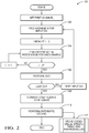
- Fig. 2 illustrates a non-limiting example of a method 100 to perform the data-compression 36.
- the average-value 38 of the sampled-data 30 in the frame 28 for the variable selected is determined in step 102.
- the method 100 proceeds to determine the percentage-difference 44 for each instance of the sampled-data 30 in step 104, and this step is repeated 'n' times where 'n' is equal to the count 52.
- the method 100 performs the discrete cosine transformation (DCT) to provide the DCT-data 46.
- DCT-data is converted into the integer-data 48.
- step 110 the integer-data 48 is converted into the encoded-data by performing arithmetic coding.
- step 112 the compressed-data, e.g. the encoded-data 50 or the percentage-data 42, and the aforementioned symbol-table, and the average-value 38 for each of the variables are stored in the memory 34.
- Fig. 3 illustrates a non-limiting example of a method 200 for decompressing that performs steps that undo the compression of data performed by the method 100.
- a data-compression system (the system 10), a controller 32 for the system 10, and a method 100, 200 of operating the system 10 is provided.
- the percentage-data 42 can be stored in the memory34, or further compression steps can be performed before data is stored in the memory 34.
Landscapes
- Engineering & Computer Science (AREA)
- Theoretical Computer Science (AREA)
- Physics & Mathematics (AREA)
- General Physics & Mathematics (AREA)
- Mathematical Physics (AREA)
- Mathematical Analysis (AREA)
- Mathematical Optimization (AREA)
- Pure & Applied Mathematics (AREA)
- Computational Mathematics (AREA)
- Data Mining & Analysis (AREA)
- General Engineering & Computer Science (AREA)
- Algebra (AREA)
- Databases & Information Systems (AREA)
- Software Systems (AREA)
- Discrete Mathematics (AREA)
- Human Computer Interaction (AREA)
- Compression, Expansion, Code Conversion, And Decoders (AREA)
Abstract
Description
- This disclosure generally relates to a data-compression system, and more particularly relates to a system that determines an average-value of sampled-data, and converts the sampled-data to percentage-data using the average-value as the basis for the conversion.
- It is desirable to store sampled data from an electronic control unit (ECU) in a vehicle to diagnose the operation of the vehicle. However, the amount of data that can be collected from the vehicle can easily be greater that the storage capacity of readily available data-collection systems.
- Some known data-collection systems capture and store block or groups of data which in some instances are referred to as freeze-frame data which are stored as captured in the memory of the data-collection system. As vehicles get more complicated, the amount of data collected to diagnose a failure mode that includes data measured before and after an event often exceeds the storage capacity and/or storage speed of typical examples of these systems. However, it was recognized that vehicle conditions don't change drastically over a short period of time. That is, most of the data remains within some expected tolerance during the time-interval that the freeze-frame data is collected.
- In general, the freeze-frame data is used to identify an anomaly in the signal so it is important to capture that moment. There are several compression methods already available for signal compression which can be used, but a compression method tailored for specific application can provide fast compression and better compression ratio. Described herein are a system and a method to reduce size of freeze-frame data captured or recorded from a vehicle. The freeze-frame data generally consists of or includes several software variables which are of different types, e.g. integer, floating point, etc. The system may be configured or programmed to carry out the steps of the method, where the method may include, but are not limited to, the steps of: determining a sample-size or count of freeze-frame data to be captured; capturing the count of sampled-data; finding an average-value of the sampled data for each variable captured in the freeze-frame; converting the sampled-data into a set of percentage-data using the average-value as a basis for the conversion; converting the percentage-data from time-domain to frequency domain by performing discrete cosine transformation (DCT) to produce DCT-data; converting the DCT-data from floating point to integer by rounding to nearest integer value to produce integer-data; encoding the integer-data using standard arithmetic coding or Huffman's coding to produce encoded-data; storing the encoded-data, a symbol-table that consists of a symbol-list and a symbol-count-list, and an average value list in a memory device.
- Therefore in accordance with one embodiment, the controller is further configured to convert the percentage-data to discrete cosine transform-data (DCT-data) by applying a discrete cosine transform (DCT) to the percentage-data, convert the DCT-data to integer-data, and encode the integer-data using standard arithmetic coding to produce encoded-data.
- In accordance with one embodiment the controller is further configured to store the encoded-data, the average-value, and a count of instances of the sampled-data in the frame.
- The sample-size or count may correspond to a value of 2n where n is between three (3) and eight (8).
- The percentage-data may correspond to a percentage-difference relative to the average-value of each instance of the sample-data.
- The average-value may be calculated either as an overall average of said sample size for each software variable or as a running average as in for every sample read the value is averaged with previous average value and samples percentage-difference relative to the current average is calculated.
- Therefore in accordance with one embodiment, the average-value is characterized as a running-average of a count of prior instances of the sampled-data.
- The floating to integer conversion may be to the nearest integer
- The arithmetic coding may use a sixteen-bit encoding method which may be Huffman coding.
- In accordance with one embodiment, a data-compression system for compressing and storing sampled data from an electronic control unit (ECU) in an automated vehicle is provided. The system includes an input and a controller. The input receives and samples a signal during a time-interval to provide a frame of sampled-data. The controller is in communication with the input. The controller is configured to capture the frame of sampled-data; determine an average-value of the sampled-data in the frame, and convert the sampled-data to percentage-data using the average-value as the basis for the conversion.
- Further features and advantages will appear more clearly on a reading of the following detailed description of the preferred embodiment, which is given by way of non-limiting example only and with reference to the accompanying drawings.
- The present invention will now be described, by way of example with reference to the accompanying drawings, in which:
-
Fig. 1 is a diagram of a data-compression system in accordance with one embodiment; -
Fig. 2 is flowchart of a method carried out by the system ofFig. 1 in accordance with one embodiment; and -
Fig. 3 is flowchart of a method carried out by the system ofFig. 1 in accordance with one embodiment. -
Fig. 1 illustrates a non-limiting example of a data-compression system 10, hereafter referred to as thesystem 10. In general, thesystem 10 is suitable for compressing and storing sampled data from an electronic control unit 20 (ECU 20) in an automated vehicle, e.g. a host-vehicle 12. As used herein, the term automated vehicle may apply to instances when the host-vehicle 12 is being operated in an automated-mode 14, i.e. a fully autonomous mode, where a human-operator (not shown) of the host-vehicle 12 may do little more than designate a destination in order to operate the host-vehicle 12. However, full automation is not a requirement. It is contemplated that the teachings presented herein are useful when the host-vehicle 12 is operated in a manual-mode 16 where the degree or level of automation may be little more than providing an audible or visual warning to the human-operator who is generally in control of the steering, accelerator, and brakes of the host-vehicle 12. For example, thesystem 10 may merely assist the human-operator as needed to change lanes and/or avoid interference with and/or a collision with, for example, an object such as another-vehicle, a pedestrian, or a road sign. - The
system 10 includes aninput 22 that receives and samples asignal 24 during a time-interval 26 to provide aframe 28 of sampled-data 30. Thesignal 24 may be communicated to theinput 22 by way of wires, optical-cable, or wireless communication, as will be recognized by those in the art. Thesignal 24 may be formed of or includes a single data-stream, or may include multiple different data-streams indicated of a variety of types of data from the ECU such as, but not limited to, ambient-temperature, fuel-injector-duty-cycle, throttle-position, mass-airflow-rate, and the like. Theinput 22 may include a commercially available analog-to-digital convertor (A/D) with a selectable sample rate. The time-interval 26 may be preselected by a user (not show) of thesystem 10, or the time-interval 26 may be selected dynamically based on the content of thesignal 24. As such, the time-interval 26 may be from a few milliseconds to several minutes depending on the interests of the user. As used herein, theframe 28 of the sampled-data 30 refers to that group or block of data that is received by theinput 22 during the time-interval 26. As noted above, theframe 28 may contain a time-sampling of a single data-variable available from the ECU, or may contain a time-sampling of several distinct data-variables such as those noted above. - The
system 10 includes acontroller 32 in communication with theinput 22. Thecontroller 32 may include a processor (not specifically shown) such as a microprocessor or other control circuitry such as analog and/or digital control circuitry including an application specific integrated circuit (ASIC) for processing data as should be evident to those in the art. Thecontroller 32 may include or may be in communication with amemory 34, including non-volatile memory, such as electrically erasable programmable read-only memory (EEPROM) for storing one or more routines, thresholds, and captured data. The one or more routines may be executed by the processor to perform steps for capturing and processing data from theECU 20 based on signals received by thecontroller 32 from the ECU and/or a user-interface (not shown) such as a keyboard and/or a display, optionally a touch-sensitive display as will be recognized by those in the art. - The
controller 32 is configured or programmed to capture theframe 28 of the sampled-data 30 which may be by way of storing theframe 28 in thememory 34, or a more temporary fast input/output type of memory such as random-access-memory (RAM) that may be integrated in the aforementioned processor. Temporary storage in the RAM maybe preferable as subsequent steps or processes performed by thecontroller 32 to perform a data-compressing 36 of the frame 28 (of the sampled-data 30) will advantageously result in a smaller amount of thememory 34 being occupied, as will be explained in more detail below. - As part of the data-
compression 36, thecontroller 32 determines an average-value 38 of the sampled-data 30 in theframe 28. By way of example and not limitation, theframe 28 may consist of two-hundred-fifty-six (256) samples of fifteen (15) different variables captured from theECU 20 during the time-interval 26. Accordingly, 15 distinct values of the average-value 38 are calculated for each of the 15 different variables by adding up all 256 samples for each variable and then dividing by 256. This example of how the average-value 38 is calculated is sometimes called a simple average. - Alternatively, the average-
value 38 may be characterized as a running-average 40 of acount 52 of prior instances of the sampled-data 30. For example, the average-value 38 for a variable may be based on an average of the latest value of the variable and one or more of the most recent values. That is, the running-average 40 for a variable may be the average of the two most recent instances of the sampled-data 30. The advantage of using the running-average 40 is that the data can be compressed as describe below in an 'on the fly' manner. In contrast, a disadvantage of the simple-average describe above is that all of the sampled-data 30 must be temporarily stored until the average-value 38 can be calculated However, a disadvantage of the runningaverage 40 is that the each data stored may be compressed using a different value of the average-value 38. - The next step of the data-
compression 36 is to convert the sampled-data 30 to percentage-data 42 using the average-value 38 as the basis for the conversion. For example, each instance of the sampled-data 30 for a particular variable may be divided by the average-value 38 associated with that instance of the sampled-data 30 in theframe 28. As such, the percentage-data 42 corresponds to a percentage-difference 44 relative to the average-value 38 of each instance of the sampled-data 30. Note that by performing this step the variable values now fluctuate around zero since the average-value 38 has been 'removed'. - Further compressing of data may be realized if the
controller 32 is further configured to convert the percentage-data 42 to discrete cosine transform-data 46 (DCT-data 46) by applying a discrete cosine transform (DCT) to the percentage-data 42, convert the DCT-data 46 to integer-data 48, and encode the integer-data using standard arithmetic coding or Huffman's coding to produce encoded-data 50. - Once the selected steps of the data-
compression 36 is complete, thecontroller 32 may store in thememory 34 data that corresponds to, or is, the percentage-data 42 (or the encoded-data 50 if subsequent processing of the percentage-data 42 is selected), the average-value 38, a symbol-table that consists of a symbol-list and a symbol-count-list, i.e. the thecount 52 of instances of the sampled-data 30 in theframe 28. - As will be recognized by those in the art, the steps taken to perform the data-
compression 36 may be reversed to de-compress the data stored in thememory 34 so that the data that corresponds to or matches the sampled-data 30 can be recovered. -
Fig. 2 illustrates a non-limiting example of amethod 100 to perform the data-compression 36. For each channel at theinput 22, i.e. for each variable selected for collection from theECU 20, the average-value 38 of the sampled-data 30 in theframe 28 for the variable selected is determined instep 102. Once the average-value 38 known, themethod 100 proceeds to determine the percentage-difference 44 for each instance of the sampled-data 30 instep 104, and this step is repeated 'n' times where 'n' is equal to thecount 52. Inoptional step 106, themethod 100 performs the discrete cosine transformation (DCT) to provide the DCT-data 46. Inoptional step 108 the DCT-data is converted into the integer-data 48. Inoptional step 110 the integer-data 48 is converted into the encoded-data by performing arithmetic coding. Instep 112, the compressed-data, e.g. the encoded-data 50 or the percentage-data 42, and the aforementioned symbol-table, and the average-value 38 for each of the variables are stored in thememory 34. -
Fig. 3 illustrates a non-limiting example of amethod 200 for decompressing that performs steps that undo the compression of data performed by themethod 100. - Accordingly, a data-compression system (the system 10), a
controller 32 for thesystem 10, and amethod system 10 is provided. By determining the percentage-difference 44 of each instance of the sampled-data 30, the percentage-data 42 can be stored in the memory34, or further compression steps can be performed before data is stored in thememory 34. - While this invention has been described in terms of the preferred embodiments thereof, it is not intended to be so limited, but rather only to the extent set forth in the claims that follow.
Claims (5)
- A data-compression system (10) for compressing and storing sampled data from an electronic control unit (20) (ECU (20)) in an automated vehicle, said system (10) comprising:an input (22) that receives and samples a signal (24) during a time-interval (26) to provide a frame (28) of sampled-data (30); anda controller (32) in communication with the input (22), said controller (32) configured to capture the frame (28) of sampled-data (30); determine an average-value (38) of the sampled-data (30) in the frame (28), and convert the sampled-data (30) to percentage-data (42) using the average-value (38) as the basis for the conversion.
- The system (10) in accordance with claim 1, wherein the percentage-data (42) corresponds to a percentage-difference (44) relative to the average-value (38) of each instance of the sample-data.
- The system (10) in accordance with any preceding claim, wherein the controller (32) is further configured to convert the percentage-data (42) to discrete cosine transform-data (46) (DCT-data (46)) by applying a discrete cosine transform (DCT) to the percentage-data (42), convert the DCT-data (46) to integer-data (48), and encode the integer-data (48) using standard arithmetic coding to produce encoded-data (50).
- The system (10) in accordance with claim 3, wherein the controller (32) is further configured to store the encoded-data (50), the average-value (38), and a count (52) of instances of the sampled-data (30) in the frame (28).
- The system (10) in accordance with any preceding claim, wherein the average-value (38) is characterized as a running-average (40) of a count (52) of prior instances of the sampled-data (30).
Applications Claiming Priority (1)
| Application Number | Priority Date | Filing Date | Title |
|---|---|---|---|
| US15/490,367 US10411730B2 (en) | 2017-04-18 | 2017-04-18 | Data compression system for storing data from an automated vehicle |
Publications (1)
| Publication Number | Publication Date |
|---|---|
| EP3393045A1 true EP3393045A1 (en) | 2018-10-24 |
Family
ID=61911377
Family Applications (1)
| Application Number | Title | Priority Date | Filing Date |
|---|---|---|---|
| EP18164809.8A Withdrawn EP3393045A1 (en) | 2017-04-18 | 2018-03-28 | Data compression system for storing data from an automated vehicle |
Country Status (2)
| Country | Link |
|---|---|
| US (1) | US10411730B2 (en) |
| EP (1) | EP3393045A1 (en) |
Citations (2)
| Publication number | Priority date | Publication date | Assignee | Title |
|---|---|---|---|---|
| GB2483282A (en) * | 2010-09-03 | 2012-03-07 | Advanced Risc Mach Ltd | Data compression and decompression using relative and absolute delta values |
| EP2819412A1 (en) * | 2013-06-06 | 2014-12-31 | Fujitsu Semiconductor Limited | Encoding and decoding |
Family Cites Families (3)
| Publication number | Priority date | Publication date | Assignee | Title |
|---|---|---|---|---|
| US5675382A (en) * | 1996-04-08 | 1997-10-07 | Connectix Corporation | Spatial compression and decompression for video |
| US20050193408A1 (en) * | 2000-07-24 | 2005-09-01 | Vivcom, Inc. | Generating, transporting, processing, storing and presenting segmentation information for audio-visual programs |
| US8126283B1 (en) * | 2005-10-13 | 2012-02-28 | Maxim Integrated Products, Inc. | Video encoding statistics extraction using non-exclusive content categories |
-
2017
- 2017-04-18 US US15/490,367 patent/US10411730B2/en active Active
-
2018
- 2018-03-28 EP EP18164809.8A patent/EP3393045A1/en not_active Withdrawn
Patent Citations (2)
| Publication number | Priority date | Publication date | Assignee | Title |
|---|---|---|---|---|
| GB2483282A (en) * | 2010-09-03 | 2012-03-07 | Advanced Risc Mach Ltd | Data compression and decompression using relative and absolute delta values |
| EP2819412A1 (en) * | 2013-06-06 | 2014-12-31 | Fujitsu Semiconductor Limited | Encoding and decoding |
Also Published As
| Publication number | Publication date |
|---|---|
| US20180302103A1 (en) | 2018-10-18 |
| US10411730B2 (en) | 2019-09-10 |
Similar Documents
| Publication | Publication Date | Title |
|---|---|---|
| CN117278643B (en) | Vehicle cloud calibration data transmission system based on cloud-edge collaboration | |
| JP7226938B2 (en) | Driving evaluation system, driving evaluation method, program, and medium | |
| US8321084B2 (en) | Control device, control method, control device of vehicle, and control system of vehicle | |
| EP3171553A1 (en) | Method for transmitting data of at least one measurement recorder of a control network, transmitter, receiver, measurement recording device and control network | |
| CN110991504A (en) | MOTCN-AE-based multi-dimensional time sequence abnormal value detection method and system | |
| US10809977B2 (en) | Analysis device, analysis method, and computer readable medium | |
| EP2702585A1 (en) | Frame based audio signal classification | |
| US11427141B2 (en) | Computing system, server and on-vehicle device | |
| CN112802227A (en) | Acquisition method and device for vehicle ADAS driving data, man-machine interaction device and vehicle | |
| CN112158149A (en) | Method and system for identifying clamping stagnation of accelerator pedal | |
| JP2019159659A (en) | Information processing device | |
| EP3161809B1 (en) | Vehicle classification system and method | |
| US10411730B2 (en) | Data compression system for storing data from an automated vehicle | |
| JP2001272466A (en) | Radar equipment | |
| CN119116971A (en) | Driving intention recognition method, device, equipment and storage medium | |
| CN117135686A (en) | A Bluetooth-based vehicle information interaction method and system | |
| CN111130552A (en) | Data compression method, data compression system and vehicle ECU adopting same | |
| CN111262652A (en) | FM0 coding decoding method and system based on edge detection | |
| CN110931021B (en) | Audio signal processing method and device | |
| DE102010062567A1 (en) | Method, sensor module and system for data transmission | |
| CN113542225A (en) | Data compression method and device, terminal equipment and storage medium | |
| US12464326B2 (en) | Method for transmitting a plurality of signals and method for receiving a plurality of signals | |
| WO2011012447A1 (en) | Electronic sensor signal-evaluating circuit in motor vehicles | |
| KR20190069789A (en) | Method and apparatus for efficient sensor data compression and decompression for low rate wireless communication | |
| CN113506065A (en) | Distribution track correction method and device |
Legal Events
| Date | Code | Title | Description |
|---|---|---|---|
| PUAI | Public reference made under article 153(3) epc to a published international application that has entered the european phase |
Free format text: ORIGINAL CODE: 0009012 |
|
| STAA | Information on the status of an ep patent application or granted ep patent |
Free format text: STATUS: THE APPLICATION HAS BEEN PUBLISHED |
|
| AK | Designated contracting states |
Kind code of ref document: A1 Designated state(s): AL AT BE BG CH CY CZ DE DK EE ES FI FR GB GR HR HU IE IS IT LI LT LU LV MC MK MT NL NO PL PT RO RS SE SI SK SM TR |
|
| AX | Request for extension of the european patent |
Extension state: BA ME |
|
| STAA | Information on the status of an ep patent application or granted ep patent |
Free format text: STATUS: REQUEST FOR EXAMINATION WAS MADE |
|
| 17P | Request for examination filed |
Effective date: 20190424 |
|
| RBV | Designated contracting states (corrected) |
Designated state(s): AL AT BE BG CH CY CZ DE DK EE ES FI FR GB GR HR HU IE IS IT LI LT LU LV MC MK MT NL NO PL PT RO RS SE SI SK SM TR |
|
| STAA | Information on the status of an ep patent application or granted ep patent |
Free format text: STATUS: EXAMINATION IS IN PROGRESS |
|
| 17Q | First examination report despatched |
Effective date: 20201022 |
|
| STAA | Information on the status of an ep patent application or granted ep patent |
Free format text: STATUS: THE APPLICATION IS DEEMED TO BE WITHDRAWN |
|
| 18D | Application deemed to be withdrawn |
Effective date: 20210504 |