EP3393003A1 - Battery charge control algorithm - Google Patents
Battery charge control algorithm Download PDFInfo
- Publication number
- EP3393003A1 EP3393003A1 EP17873092.5A EP17873092A EP3393003A1 EP 3393003 A1 EP3393003 A1 EP 3393003A1 EP 17873092 A EP17873092 A EP 17873092A EP 3393003 A1 EP3393003 A1 EP 3393003A1
- Authority
- EP
- European Patent Office
- Prior art keywords
- battery
- charging mode
- average
- discharge current
- charge
- Prior art date
- Legal status (The legal status is an assumption and is not a legal conclusion. Google has not performed a legal analysis and makes no representation as to the accuracy of the status listed.)
- Granted
Links
Images

Classifications
-
- H—ELECTRICITY
- H01—ELECTRIC ELEMENTS
- H01M—PROCESSES OR MEANS, e.g. BATTERIES, FOR THE DIRECT CONVERSION OF CHEMICAL ENERGY INTO ELECTRICAL ENERGY
- H01M10/00—Secondary cells; Manufacture thereof
- H01M10/42—Methods or arrangements for servicing or maintenance of secondary cells or secondary half-cells
- H01M10/44—Methods for charging or discharging
-
- H—ELECTRICITY
- H01—ELECTRIC ELEMENTS
- H01M—PROCESSES OR MEANS, e.g. BATTERIES, FOR THE DIRECT CONVERSION OF CHEMICAL ENERGY INTO ELECTRICAL ENERGY
- H01M10/00—Secondary cells; Manufacture thereof
- H01M10/42—Methods or arrangements for servicing or maintenance of secondary cells or secondary half-cells
- H01M10/425—Structural combination with electronic components, e.g. electronic circuits integrated to the outside of the casing
-
- H—ELECTRICITY
- H01—ELECTRIC ELEMENTS
- H01M—PROCESSES OR MEANS, e.g. BATTERIES, FOR THE DIRECT CONVERSION OF CHEMICAL ENERGY INTO ELECTRICAL ENERGY
- H01M10/00—Secondary cells; Manufacture thereof
- H01M10/42—Methods or arrangements for servicing or maintenance of secondary cells or secondary half-cells
- H01M10/44—Methods for charging or discharging
- H01M10/443—Methods for charging or discharging in response to temperature
-
- H—ELECTRICITY
- H01—ELECTRIC ELEMENTS
- H01M—PROCESSES OR MEANS, e.g. BATTERIES, FOR THE DIRECT CONVERSION OF CHEMICAL ENERGY INTO ELECTRICAL ENERGY
- H01M10/00—Secondary cells; Manufacture thereof
- H01M10/42—Methods or arrangements for servicing or maintenance of secondary cells or secondary half-cells
- H01M10/48—Accumulators combined with arrangements for measuring, testing or indicating the condition of cells, e.g. the level or density of the electrolyte
-
- H—ELECTRICITY
- H01—ELECTRIC ELEMENTS
- H01M—PROCESSES OR MEANS, e.g. BATTERIES, FOR THE DIRECT CONVERSION OF CHEMICAL ENERGY INTO ELECTRICAL ENERGY
- H01M10/00—Secondary cells; Manufacture thereof
- H01M10/42—Methods or arrangements for servicing or maintenance of secondary cells or secondary half-cells
- H01M10/48—Accumulators combined with arrangements for measuring, testing or indicating the condition of cells, e.g. the level or density of the electrolyte
- H01M10/486—Accumulators combined with arrangements for measuring, testing or indicating the condition of cells, e.g. the level or density of the electrolyte for measuring temperature
-
- H—ELECTRICITY
- H02—GENERATION; CONVERSION OR DISTRIBUTION OF ELECTRIC POWER
- H02J—ELECTRIC POWER NETWORKS; CIRCUIT ARRANGEMENTS OR SYSTEMS FOR SUPPLYING OR DISTRIBUTING ELECTRIC POWER; SYSTEMS FOR STORING ELECTRIC ENERGY
- H02J7/00—Circuit arrangements for charging or discharging batteries or for supplying loads from batteries
- H02J7/02—Circuit arrangements for charging or discharging batteries or for supplying loads from batteries for charging batteries from AC mains by converters
- H02J7/04—Regulation of charging current or voltage
-
- H—ELECTRICITY
- H02—GENERATION; CONVERSION OR DISTRIBUTION OF ELECTRIC POWER
- H02J—ELECTRIC POWER NETWORKS; CIRCUIT ARRANGEMENTS OR SYSTEMS FOR SUPPLYING OR DISTRIBUTING ELECTRIC POWER; SYSTEMS FOR STORING ELECTRIC ENERGY
- H02J7/00—Circuit arrangements for charging or discharging batteries or for supplying loads from batteries
- H02J7/90—Regulation of charging or discharging current or voltage
- H02J7/94—Regulation of charging or discharging current or voltage in response to battery current
- H02J7/947—Regulation of charging or discharging current or voltage in response to battery current in response to integrated charge or discharge current
-
- H—ELECTRICITY
- H02—GENERATION; CONVERSION OR DISTRIBUTION OF ELECTRIC POWER
- H02J—ELECTRIC POWER NETWORKS; CIRCUIT ARRANGEMENTS OR SYSTEMS FOR SUPPLYING OR DISTRIBUTING ELECTRIC POWER; SYSTEMS FOR STORING ELECTRIC ENERGY
- H02J7/00—Circuit arrangements for charging or discharging batteries or for supplying loads from batteries
- H02J7/90—Regulation of charging or discharging current or voltage
- H02J7/971—Regulation of charging or discharging current or voltage the charge cycle being controlled or terminated in response to non-electric parameters
- H02J7/975—Regulation of charging or discharging current or voltage the charge cycle being controlled or terminated in response to non-electric parameters in response to temperature
-
- H—ELECTRICITY
- H01—ELECTRIC ELEMENTS
- H01M—PROCESSES OR MEANS, e.g. BATTERIES, FOR THE DIRECT CONVERSION OF CHEMICAL ENERGY INTO ELECTRICAL ENERGY
- H01M10/00—Secondary cells; Manufacture thereof
- H01M10/42—Methods or arrangements for servicing or maintenance of secondary cells or secondary half-cells
- H01M10/425—Structural combination with electronic components, e.g. electronic circuits integrated to the outside of the casing
- H01M2010/4271—Battery management systems including electronic circuits, e.g. control of current or voltage to keep battery in healthy state, cell balancing
Definitions
- the present disclosure relates to an algorithm for controlling an output specification of a charger according to a battery usage pattern, more particularly, to an algorithm for analyzing a usage pattern of a battery built in a user's system through a self-analysis and controlling a battery charging scheme suitable for the analyzed pattern, thereby extending the service life of the battery.
- a battery charging method that does not take into account the usage habits of the user has a problem of shortening the service life of the battery.
- the present invention provides a charging control method for extending the service life of a battery by controlling the charging method suitable for the battery usage pattern of a user such as usage habits of the battery user, usage temperature, and the like.
- a battery charge control system includes: a battery pack including at least one battery cell; a data measurement unit configured to measure a discharge current, a charge time, a temperature of the battery cell; a data calculation unit configured to calculate an average discharge current rate, an average charge time, and an average temperature of the battery; and a charging mode calculation unit configured to calculate a charging mode of a predetermined battery based on each of the calculated average discharge current rate, average charge time, and average temperature, wherein the data measurement unit includes: a discharge current measurement unit configured to measure a discharge current of a battery cell at predetermined period intervals; a charge time measurement unit configured to measure a time during which the battery is being charged by detecting a time point that the battery is connected to a battery charge device; and a temperature measurement unit configured to measure a temperature of a battery cell at the predetermined period intervals, wherein the data calculation unit includes: an average discharge current calculation unit configured to calculate an average discharge current rate of a battery from a discharge current of a battery cell measured in
- the calculation of the predetermined battery charging mode in the charging mode calculation unit may detect a predetermined each section that each of the calculated average discharge current rate, average charge time, and average temperature value of the battery belongs, and derive each division factor corresponding to the detected section to calculate a battery charging mode determined by a combination of each of the derived division factors.
- the charging mode calculation unit may perform the battery charging mode calculation periodically at predetermined intervals, and compare each of division factors derived from a previous period with each of division factors derived from a current period, and when the same division factor exists, update the charging mode at the current period by adding a predetermined weight value to the division factor determined to be the same.
- a method of controlling charging of a battery configured including at least one battery cell includes: a discharge current measurement operation for measuring a discharge current of the battery cell at predetermined period intervals; a charge time measurement operation for measuring a time during which the battery is being charged by detecting a time point that the battery is connected to a battery charge device; a temperature measurement operation for measuring a temperature of the battery cell at the predetermined period intervals; an average discharge current rate calculation operation for calculating an average discharge current rate of a battery from a discharge current of a battery cell measured at the predetermined period intervals; an average charge time calculation operation for calculating an average charge time of a battery based on the measured charge time of the battery; an average temperature calculation operation for calculating an average temperature of a battery based on the temperature measured at the predetermined period intervals; and a charging mode calculation operation for calculating a predetermined battery charging mode based on each of the calculated average discharge current rate, average charge time, and average temperature of the battery.
- the charging mode calculation operation may be performed periodically at the predetermined intervals, and include: detecting a predetermined each section that each of the calculated average discharge current rate, average charge time, and average temperature value of the battery belongs, and deriving each division factor corresponding to the detected section to calculate a battery charging mode determined by a combination of each of the derived division factors.
- the charging mode calculation operation may further include a charging mode providing operation for providing the calculated battery charging to the battery charge device.
- the charging mode calculation operation may perform the battery charging mode calculation periodically at predetermined intervals, and compare each of division factors derived from a previous period with each of division factors derived from a current period, and when the same division factor exists, update the charging mode at the current period by adding a predetermined weight value to the division factor determined to the same.
- the charging mode calculation unit may provide the calculated battery charging mode to a battery charge device.
- the battery charge control system may further include a charge control unit, wherein the charging mode calculation unit may provide the calculated battery charging mode to the charge control unit.
- the charge control unit may control the battery charge device to operate according to the received battery charging mode.
- the charge control unit may receive an output of the battery charge device and convert the output of the battery charge device according to the received battery charging mode to output the converted output to a battery.
- first may be referred to as a second component and vice versa without departing from the scope of the present invention.
- Terms used in this specification are used to describe specific embodiments, and are not intended to limit the scope of the present invention.
- the singular expressions include plural expressions unless the context clearly dictates otherwise.
- a battery charge control system includes: a battery pack including at least one battery cell; a data measurement unit configured to measure a discharge current, a charge time, a temperature of the battery cell; a data calculation unit configured to calculate an average discharge current rate, an average charge time, and an average temperature of the battery; and a charging mode calculation unit configured to calculate a charging mode of a predetermined battery based on each of the calculated average discharge current rate, average charge time, and average temperature.
- the data measurement unit includes: a discharge current measurement unit configured to measure a discharge current of a battery cell at predetermined period intervals; a charge time measurement unit configured to measure a time during which the battery is being charged by detecting a time point that the battery is connected to a battery charge device; and a temperature measurement unit configured to measure a temperature of a battery cell at the predetermined period intervals.
- the data calculation unit includes: an average discharge current calculation unit configured to calculate an average discharge current rate of a battery from a discharge current of a battery cell measured in the discharge current measurement unit; an average charge time calculation unit configured to calculate an average charge time of a battery based on a battery charge time measured in the charge time measurement unit; and an average temperature calculation unit configured to calculate an average temperature of a battery based on a temperature of a battery cell measured in the temperature measurement unit.
- the battery pack according to the present invention may be any IT device including a mobile phone, a notebook computer, etc. where a battery pack is built.
- the term "average”, mentioned in this specification, means, for example, an average value obtained by calculating each of the discharge current, the charging time, and the temperature value of the measured battery as an hourly value for 24 hours and calculating the hourly value for 24 hours as a value for one week.
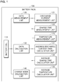
- FIG. 1 is a block diagram showing the overall system configuration according to the present invention.
- a charge control system for a battery includes a battery pack 100, a battery cell 110, a data measurement unit 120, a data calculation unit 130, and a charging mode calculation unit 140.
- the battery pack 100 may include at least one or more battery cells 110 connected in series and in parallel.
- the data measurement unit 120 may include a discharge current measurement unit 121, a charge time measurement unit 122, and a temperature measurement unit 123.
- the discharge current measurement unit 121 may measure the discharge current of the battery cell 110 at predetermined period intervals.
- the charge time measurement unit 122 may measure a time during which the battery is being charged. This may detect the connection between the battery and the battery charge device, and measure the time during which the battery is being charged.
- the temperature measurement unit 123 may measure the temperature of the battery cell 110 at predetermined period intervals.
- the data calculation unit 130 may include an average discharge current rate calculation unit 131, an average charge time calculation unit 132, and an average temperature calculation unit 133.
- the average discharge current rate calculation unit 131 may calculate an average discharge current rate based on a discharge current amount measured in the discharge current measurement unit 121 at predetermined period intervals.
- the average discharge current rate may be calculated by calculating the discharge current amount as a value for 24 hours, and calculating the value for 24-hour as an average value for one week.
- the average charge time calculation unit 132 may calculate an average charge time based on the charge time measured in the charge time measurement unit 122. For example, the measured charge time may be calculated as a value for 24 hours, and based on this, the average charge time for one week may be calculated.
- the average temperature calculation unit 133 may calculate the average temperature of the battery pack 100 based on the temperature measured in the temperature measurement unit 123. For example, the temperature measured at predetermined period intervals in the temperature measurement unit 123 may be calculated as a value for 24 hours, and based on this, the average temperature value for one week may be calculated.
- the data measurement unit 120 and the data calculation unit 130 may use a gauge IC and may be configured by implementing firmware for measuring the discharge current, the charge time, and the temperature in the gauge IC. Also, the data measurement unit 120 may receive current, voltage, and temperature measurement values of the battery measured from a BMS (not shown) of the battery.
- the charging mode calculation unit 140 may calculate a charging mode of the battery based on each of the calculated average discharge current rate, average charge time, and average temperature of the battery.
- the charging mode calculation may detect a predetermined section to which each of the calculated average discharge current rate, average charge time, and average temperature value of the battery belongs and may derive each division factor corresponding to the detected predetermined section, thereby calculating the charging mode determined by the combination of each derived division factor.
- each division factor calculated in the previous period is compared with each division factor calculated in the current period, and if the same division factor exists, the charging mode calculation unit 140 may update the charging mode in the current period by adding a predetermined weight value to the division factor determined to be the same.
- the charging mode calculation unit 140 may control charging of the battery in a charging mode suitable for the battery state by providing the calculated charging mode to the battery charge device 200.
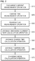
- a method of controlling charging of a battery configured including at least one battery cell includes: a discharge current measurement operation S10 for measuring a discharge current of the battery cell at predetermined period intervals; a charge time measurement operation S20 for measuring a time during which the battery is being charged by detecting a time point that the battery is connected to a battery charge device; a temperature measurement operation S30 for measuring a temperature of the battery cell at the predetermined period intervals; an average discharge current rate calculation operation S40 for calculating an average discharge current rate of a battery from a discharge current of a battery cell measured at the predetermined period intervals; an average charge time calculation operation S50 for calculating an average charge time of a battery based on the measured charge time of the battery; an average temperature calculation operation S60 for calculating an average temperature of a battery based on the temperature measured at the predetermined period intervals; and a charging mode calculation operation S70 for calculating a predetermined battery charging mode based on each of the calculated average discharge current rate, average charge time, and average temperature of the battery.
- the discharge current measurement operation S10 may be an operation of measuring a discharge current of the battery cell 110 at predetermined period intervals.
- the charge time measurement operation S20 may measure the time during which the battery is being charged by detecting the time point when the battery charge device is connected to the charge device.
- the temperature measurement operation S30 may measure the battery cell 110 at predetermined period intervals.
- the average discharge current rate calculation operation S40 may calculate an average discharge current rate of the battery based on a discharge current amount of the battery cell measured in the discharge current measurement operation S10. For example, the discharge current amount may be calculated as an hourly discharge current value for 24 hours, and based on this, an average discharge current amount for a week may be calculated.
- the average charge time calculation operation S50 may calculate an average charge time based on the charge time of the battery measured in the charge time measurement operation S20. For example, the charge time may be calculated as a value for 24 hours, and based on this, the average charge time of the battery may be calculated by calculating the average value for one week.
- the average temperature calculation operation S60 may calculate the average temperature of the battery based on the temperature measured in the temperature measurement operation S30. For example, the temperature of the battery may be calculated as a value for 24 hours, and based on this, the average temperature of the battery may be calculated by calculating the average value for one week.
- the above operations may be performed in a gauge IC, and may be configured by implementing firmware for measuring the discharge current, charge time, and temperature in the gauge IC.
- the charging mode calculation operation S70 may detect each predetermined section to which each calculated average discharge current rate, average charge time, and average temperature value of the battery belongs, and derive each division factor corresponding to the detected section. Therefore, the charging mode of the battery corresponding to the combination of the derived division factors may be calculated.
- the charging mode calculation operation S70 may provide the calculated charging mode to the battery charge device 200.
- the user mode may be defined according to the manner in which the battery is used by the user.
- User classification Major usage pattern Improvement plan Power User H eavy Load
- Mainly high current use Pattern (3D, game, etc.) Need to Improve battery life by lowering charge voltage/current Normal User ( M iddle Load) General use pattern (Office workers, etc.)
- M iddle Load General use pattern (Office workers, etc.)
- Commercial User L ight Load
- Set the charge/discharge area to use only between 40% and 80% of RSOC
- a division factor for each range may be calculated by referring to Table 2 to 4 below.
- [Table 2] 0.4C-rate or less Between 0.4-0.8C rate 0.8C rate or more Discharge current rate A B C
- [Table 3] 56 hours or less Between 56-84 hours 84 hours or more Charge time A' B' C' [Table 4] 20 degrees or less Between 20-40 degrees 40 degrees or more Temperature A" B" C"
- each division factor corresponding to a predetermined section to which each average value calculated for the one week belongs may be calculated.
- the charging mode for charge control suitable for a battery state may be calculated by using each division factor corresponding to the predetermined calculated section.
- the charging mode of the battery may be calculated by a combination of respective division factors corresponding to the calculated average discharge current rate, average charge time, and average temperature of the battery.
- the charging of the battery may be controlled through the charging method corresponding to the calculated charging mode. Therefore, the service life of the battery may be prolonged as it is controllable by the charging method according to the state of the battery.
- each division factor calculated in the previous period is compared with each division factor calculated in the current period, and if the same division factor exists, the charging mode calculation operation S70 may update the charging mode in the current period by adding a predetermined weight value to the division factor determined to be the same.
- Updating the charging mode by adding a predetermined weight value may be performed as shown in Table 7 below.
- Table 7 Week First week Second week Third week Fourth week Weight 1 1.2 1.4 1.6
- the table 7 shows weight values set according to the period thereof. For example, if there is a division factor that is the same as the previous period (e.g., first week) in the division factors calculated in the current period (e.g., second week), the charging mode may be updated by adding a corresponding weight value of 1.2 to the division factor determined to be the same.
- the charging mode may be updated by adding the corresponding weight value of 1.4.
- the charging mode is updated by assigning a weight value set differently according to successive periods, it is possible to control the charging of the battery by determining the user pattern with more improved accuracy.
- the battery charge control system may be additionally configured with a charge control unit 210.
- the charge control unit 210 may control the battery charge device according to a battery charging mode provided from the charging mode calculation unit 140.
- the embodiment 3 of the present invention is a view briefly showing that the charge control unit 210 is configured in the battery charge device 200 to control the charging of the battery.
- the process of calculating the charging mode is the same as that described above with reference to FIGS. 1 and 2 , and will be omitted.
- the charging mode of the battery calculated in the charging mode calculation unit 140 may be provided to the battery charge device 200 as in operation S2. Therefore, by controlling the output of the current of the battery charge device 200 according to the charging mode of the battery, the charge control unit 210 configured in the battery charge device 200 may control the charging of the battery with the output according to the calculated charging mode of the battery as in operation S3.
- the embodiment 4 is a view briefly showing that the charge control unit 210 is configured outside the battery charge device to control the charging of the battery.
- the charging mode of the battery calculated in the charging mode calculation unit 140 may be inputted to the charge control unit 210 outside the battery charge device.
- the charge control unit 210 may control the output current of the battery charge device 200 to be converted according to the received charging mode. Therefore, the battery charge device 200 may control the charging of the battery as in operation S300 by outputting the charging current according to the calculated charging mode.
- the charging mode calculation unit 140 may calculate a battery charging mode and provide it to the charge control unit 210. Also, as in operation S3, the charge control unit 210 may receive the output of the battery charge device 200. Accordingly, the charge control unit 140 may convert the received output current of the battery charge device according to the provided battery charging mode, as in operation S4000 and output it to the battery as in operation S5000. Therefore, the charging of the battery may be controlled according to the calculated charging mode of the battery.
- the present invention has the effect of extending the service life of a battery by measuring the battery usage pattern and the usage environment temperature of a system user such as a mobile phone and a notebook computer and calculating a suitable charging mode to control the charging of the battery.
Landscapes
- Engineering & Computer Science (AREA)
- Manufacturing & Machinery (AREA)
- Chemical & Material Sciences (AREA)
- Chemical Kinetics & Catalysis (AREA)
- Electrochemistry (AREA)
- General Chemical & Material Sciences (AREA)
- Power Engineering (AREA)
- Microelectronics & Electronic Packaging (AREA)
- Charge And Discharge Circuits For Batteries Or The Like (AREA)
- Secondary Cells (AREA)
Abstract
Description
- The present disclosure relates to an algorithm for controlling an output specification of a charger according to a battery usage pattern, more particularly, to an algorithm for analyzing a usage pattern of a battery built in a user's system through a self-analysis and controlling a battery charging scheme suitable for the analyzed pattern, thereby extending the service life of the battery.
- Users who use IT devices such as mobile phones and laptops consider the portability that they use them anytime and anywhere regardless of time and place. The most influential factor in the portability of IT devices is the battery. Since users want to continue to use IT devices for a longer period of time, the capacity of the battery is an important part.
- However, even if the same capacity of the battery is shipped, it is common to see the difference in the usage period. This is because the life span of the battery may be affected by the usage habits of the user or the temperature of the environment when the battery is used for a longer period of time. Accordingly, various technologies are developed to extend the service life of the battery to be a longer time.
- Technology for setting the charging voltage/current to a battery without considering the usage habits or environment of the system user, and after reading it from the system, supplying the charging voltage/current corresponding thereto in order for charging in a system charger is applied to conventional battery technology of a system such as a mobile phone, a notebook computer, and the like. However, since the service life of the battery differs depending on the usage habits of the system user and the temperature of the use environment, there is a problem that the service life of the battery may be shortened depending on the user even if the battery is shipped with the same battery capacity. Also, in order to satisfy the desire of users who want to use a battery for a long time, the battery capacity should be increased. However, because of the limitations of battery capacity and battery space available in the system, a user-optimized battery charging technique to extend the service life of the battery is required.
- A battery charging method that does not take into account the usage habits of the user has a problem of shortening the service life of the battery.
- Accordingly, the present invention provides a charging control method for extending the service life of a battery by controlling the charging method suitable for the battery usage pattern of a user such as usage habits of the battery user, usage temperature, and the like.
- In accordance with an exemplary embodiment, a battery charge control system includes: a battery pack including at least one battery cell; a data measurement unit configured to measure a discharge current, a charge time, a temperature of the battery cell; a data calculation unit configured to calculate an average discharge current rate, an average charge time, and an average temperature of the battery; and a charging mode calculation unit configured to calculate a charging mode of a predetermined battery based on each of the calculated average discharge current rate, average charge time, and average temperature, wherein the data measurement unit includes: a discharge current measurement unit configured to measure a discharge current of a battery cell at predetermined period intervals; a charge time measurement unit configured to measure a time during which the battery is being charged by detecting a time point that the battery is connected to a battery charge device; and a temperature measurement unit configured to measure a temperature of a battery cell at the predetermined period intervals, wherein the data calculation unit includes: an average discharge current calculation unit configured to calculate an average discharge current rate of a battery from a discharge current of a battery cell measured in the discharge current measurement unit; an average charge time calculation unit configured to calculate an average charge time of a battery based on a battery charge time measured in the charge time measurement unit; and an average temperature calculation unit configured to calculate an average temperature of a battery based on a temperature of a battery cell measured in the temperature measurement unit.
- The calculation of the predetermined battery charging mode in the charging mode calculation unit may detect a predetermined each section that each of the calculated average discharge current rate, average charge time, and average temperature value of the battery belongs, and derive each division factor corresponding to the detected section to calculate a battery charging mode determined by a combination of each of the derived division factors.
- The charging mode calculation unit may perform the battery charging mode calculation periodically at predetermined intervals, and compare each of division factors derived from a previous period with each of division factors derived from a current period, and when the same division factor exists, update the charging mode at the current period by adding a predetermined weight value to the division factor determined to be the same.
- In accordance with another exemplary embodiment, a method of controlling charging of a battery configured including at least one battery cell includes: a discharge current measurement operation for measuring a discharge current of the battery cell at predetermined period intervals; a charge time measurement operation for measuring a time during which the battery is being charged by detecting a time point that the battery is connected to a battery charge device; a temperature measurement operation for measuring a temperature of the battery cell at the predetermined period intervals; an average discharge current rate calculation operation for calculating an average discharge current rate of a battery from a discharge current of a battery cell measured at the predetermined period intervals; an average charge time calculation operation for calculating an average charge time of a battery based on the measured charge time of the battery; an average temperature calculation operation for calculating an average temperature of a battery based on the temperature measured at the predetermined period intervals; and a charging mode calculation operation for calculating a predetermined battery charging mode based on each of the calculated average discharge current rate, average charge time, and average temperature of the battery.
- The charging mode calculation operation may be performed periodically at the predetermined intervals, and include: detecting a predetermined each section that each of the calculated average discharge current rate, average charge time, and average temperature value of the battery belongs, and deriving each division factor corresponding to the detected section to calculate a battery charging mode determined by a combination of each of the derived division factors.
- The charging mode calculation operation may further include a charging mode providing operation for providing the calculated battery charging to the battery charge device.
- The charging mode calculation operation may perform the battery charging mode calculation periodically at predetermined intervals, and compare each of division factors derived from a previous period with each of division factors derived from a current period, and when the same division factor exists, update the charging mode at the current period by adding a predetermined weight value to the division factor determined to the same.
- The charging mode calculation unit may provide the calculated battery charging mode to a battery charge device.
- The battery charge control system may further include a charge control unit, wherein the charging mode calculation unit may provide the calculated battery charging mode to the charge control unit.
- The charge control unit may control the battery charge device to operate according to the received battery charging mode.
- The charge control unit may receive an output of the battery charge device and convert the output of the battery charge device according to the received battery charging mode to output the converted output to a battery.
- Exemplary embodiments can be understood in more detail from the following description taken in conjunction with the accompanying drawings, in which:
-
FIG. 1 is a block diagram briefly showing a configuration of a system according to the present invention; -
FIG. 2 is a block diagram briefly showing an operation according to the present invention; -
FIG. 3 is a view showingembodiment 3 according to the present invention; -
FIG. 4 is a view showing embodiment 4 according to the present invention; and -
FIG. 5 is a view showing embodiment 5 according to the present invention. - Hereinafter, embodiments of the present invention will be described in detail with reference to the accompanying drawings so that those skilled in the art may easily carry out the present invention. The present invention may, however, be embodied in different forms and should not be constructed as limited to the embodiments set forth herein. Parts not relating to description are omitted in the drawings in order to clearly describe the present invention and like reference numerals refer to like elements throughout.
- Although the terms "first," "second," etc., may be used herein to describe various elements, these elements should not be limited by these terms. The above terms are used only to distinguish one component from another. For example, a first component may be referred to as a second component and vice versa without departing from the scope of the present invention. Terms used in this specification are used to describe specific embodiments, and are not intended to limit the scope of the present invention. The singular expressions include plural expressions unless the context clearly dictates otherwise.
- Throughout the specification, when a portion is referred to as being "connected" to another portion, it includes not only "directly connected" but also "electrically connected" with another element therebetween. Furthermore, when it is described that one comprises (or includes or has) some elements, it should be understood that it may comprise (or include or has) only those elements, or it may comprise (or include or have) other elements as well as those elements if there is no specific limitation. The term "∼ing operation" or "operation of ∼ing" used throughout the specification does not mean "operation for ∼ing".
- Terms used in this specification may be currently widely used general terms in consideration of functions in the present invention but may vary according to the intents of those skilled in the art, precedents, or the advent of new technology. Additionally, in certain cases, there may be terms the applicant selects arbitrarily and in this case, their meanings are described in a corresponding description part of the present invention. Accordingly, terms used in the present invention should be defined based on the meaning of the term and the entire contents of the present invention instead of the simple term name.
- A battery charge control system includes: a battery pack including at least one battery cell; a data measurement unit configured to measure a discharge current, a charge time, a temperature of the battery cell; a data calculation unit configured to calculate an average discharge current rate, an average charge time, and an average temperature of the battery; and a charging mode calculation unit configured to calculate a charging mode of a predetermined battery based on each of the calculated average discharge current rate, average charge time, and average temperature. The data measurement unit includes: a discharge current measurement unit configured to measure a discharge current of a battery cell at predetermined period intervals; a charge time measurement unit configured to measure a time during which the battery is being charged by detecting a time point that the battery is connected to a battery charge device; and a temperature measurement unit configured to measure a temperature of a battery cell at the predetermined period intervals. The data calculation unit includes: an average discharge current calculation unit configured to calculate an average discharge current rate of a battery from a discharge current of a battery cell measured in the discharge current measurement unit; an average charge time calculation unit configured to calculate an average charge time of a battery based on a battery charge time measured in the charge time measurement unit; and an average temperature calculation unit configured to calculate an average temperature of a battery based on a temperature of a battery cell measured in the temperature measurement unit.
- The battery pack according to the present invention may be any IT device including a mobile phone, a notebook computer, etc. where a battery pack is built.
- In addition, the term "average", mentioned in this specification, means, for example, an average value obtained by calculating each of the discharge current, the charging time, and the temperature value of the measured battery as an hourly value for 24 hours and calculating the hourly value for 24 hours as a value for one week.
- Hereinafter, a battery charge control system will be described in detail with reference to the drawings, as an embodiment of the present invention.
-
FIG. 1 is a block diagram showing the overall system configuration according to the present invention. - Referring to
FIG. 1 , a charge control system for a battery according to the present invention includes abattery pack 100, abattery cell 110, adata measurement unit 120, adata calculation unit 130, and a chargingmode calculation unit 140. - The
battery pack 100 may include at least one ormore battery cells 110 connected in series and in parallel. - The
data measurement unit 120 may include a dischargecurrent measurement unit 121, a chargetime measurement unit 122, and atemperature measurement unit 123. - The discharge
current measurement unit 121 may measure the discharge current of thebattery cell 110 at predetermined period intervals. - The charge
time measurement unit 122 may measure a time during which the battery is being charged. This may detect the connection between the battery and the battery charge device, and measure the time during which the battery is being charged. - The
temperature measurement unit 123 may measure the temperature of thebattery cell 110 at predetermined period intervals. - The
data calculation unit 130 may include an average discharge currentrate calculation unit 131, an average chargetime calculation unit 132, and an averagetemperature calculation unit 133. - The average discharge current
rate calculation unit 131 may calculate an average discharge current rate based on a discharge current amount measured in the dischargecurrent measurement unit 121 at predetermined period intervals. - For example, the average discharge current rate may be calculated by calculating the discharge current amount as a value for 24 hours, and calculating the value for 24-hour as an average value for one week.
- The average charge
time calculation unit 132 may calculate an average charge time based on the charge time measured in the chargetime measurement unit 122. For example, the measured charge time may be calculated as a value for 24 hours, and based on this, the average charge time for one week may be calculated. - The average
temperature calculation unit 133 may calculate the average temperature of thebattery pack 100 based on the temperature measured in thetemperature measurement unit 123. For example, the temperature measured at predetermined period intervals in thetemperature measurement unit 123 may be calculated as a value for 24 hours, and based on this, the average temperature value for one week may be calculated. - The
data measurement unit 120 and thedata calculation unit 130 may use a gauge IC and may be configured by implementing firmware for measuring the discharge current, the charge time, and the temperature in the gauge IC. Also, thedata measurement unit 120 may receive current, voltage, and temperature measurement values of the battery measured from a BMS (not shown) of the battery. - The charging
mode calculation unit 140 may calculate a charging mode of the battery based on each of the calculated average discharge current rate, average charge time, and average temperature of the battery. - The charging mode calculation may detect a predetermined section to which each of the calculated average discharge current rate, average charge time, and average temperature value of the battery belongs and may derive each division factor corresponding to the detected predetermined section, thereby calculating the charging mode determined by the combination of each derived division factor.
- Also, each division factor calculated in the previous period is compared with each division factor calculated in the current period, and if the same division factor exists, the charging
mode calculation unit 140 may update the charging mode in the current period by adding a predetermined weight value to the division factor determined to be the same. - In addition, the charging
mode calculation unit 140 may control charging of the battery in a charging mode suitable for the battery state by providing the calculated charging mode to thebattery charge device 200. - Hereinafter, a battery charge control method according to the present invention will be described with reference to
FIG. 2 . - A method of controlling charging of a battery configured including at least one battery cell includes: a discharge current measurement operation S10 for measuring a discharge current of the battery cell at predetermined period intervals; a charge time measurement operation S20 for measuring a time during which the battery is being charged by detecting a time point that the battery is connected to a battery charge device; a temperature measurement operation S30 for measuring a temperature of the battery cell at the predetermined period intervals; an average discharge current rate calculation operation S40 for calculating an average discharge current rate of a battery from a discharge current of a battery cell measured at the predetermined period intervals; an average charge time calculation operation S50 for calculating an average charge time of a battery based on the measured charge time of the battery; an average temperature calculation operation S60 for calculating an average temperature of a battery based on the temperature measured at the predetermined period intervals; and a charging mode calculation operation S70 for calculating a predetermined battery charging mode based on each of the calculated average discharge current rate, average charge time, and average temperature of the battery.
- The discharge current measurement operation S10 may be an operation of measuring a discharge current of the
battery cell 110 at predetermined period intervals. - The charge time measurement operation S20 may measure the time during which the battery is being charged by detecting the time point when the battery charge device is connected to the charge device.
- The temperature measurement operation S30 may measure the
battery cell 110 at predetermined period intervals. - The average discharge current rate calculation operation S40 may calculate an average discharge current rate of the battery based on a discharge current amount of the battery cell measured in the discharge current measurement operation S10. For example, the discharge current amount may be calculated as an hourly discharge current value for 24 hours, and based on this, an average discharge current amount for a week may be calculated.
- The average charge time calculation operation S50 may calculate an average charge time based on the charge time of the battery measured in the charge time measurement operation S20. For example, the charge time may be calculated as a value for 24 hours, and based on this, the average charge time of the battery may be calculated by calculating the average value for one week.
- The average temperature calculation operation S60 may calculate the average temperature of the battery based on the temperature measured in the temperature measurement operation S30. For example, the temperature of the battery may be calculated as a value for 24 hours, and based on this, the average temperature of the battery may be calculated by calculating the average value for one week.
- The above operations may be performed in a gauge IC, and may be configured by implementing firmware for measuring the discharge current, charge time, and temperature in the gauge IC.
- The charging mode calculation operation S70 may detect each predetermined section to which each calculated average discharge current rate, average charge time, and average temperature value of the battery belongs, and derive each division factor corresponding to the detected section. Therefore, the charging mode of the battery corresponding to the combination of the derived division factors may be calculated.
- Also, the charging mode calculation operation S70 may provide the calculated charging mode to the
battery charge device 200. - To describe the method of calculating the charging mode, the description will be made with reference to a table according to an embodiment of the present invention.
- First, as shown in Table 1, the user mode may be defined according to the manner in which the battery is used by the user.
[Table 1] User classification Major usage pattern Improvement plan Power User (Heavy Load) Mainly high current use Pattern (3D, game, etc.) Need to Improve battery life by lowering charge voltage/current Normal User (Middle Load) General use pattern (Office workers, etc.) After analyzing user's usage pattern, 1) Need to improve by lowering charge voltage/current 2) Automatic charge/discharge for capacity loss and accurate capacity estimation of battery by self-discharge Commercial User (Light Load) Pattern using plugged-in charger always 1) Automatic charge/discharge for battery capacity loss and accurate capacity measurement due to self-discharge 2) Set the charge/discharge area to use only between 40% and 80% of RSOC - A division factor for each range may be calculated by referring to Table 2 to 4 below.
[Table 2] 0.4C-rate or less Between 0.4-0.8C rate 0.8C rate or more Discharge current rate A B C [Table 3] 56 hours or less Between 56-84 hours 84 hours or more Charge time A' B' C' [Table 4] 20 degrees or less Between 20-40 degrees 40 degrees or more Temperature A" B" C" - As shown in Table 2 to 4, by setting a division factor for each discharge current rate, charge time, and temperature of the battery, each division factor corresponding to a predetermined section to which each average value calculated for the one week belongs may be calculated.
- The charging mode for charge control suitable for a battery state may be calculated by using each division factor corresponding to the predetermined calculated section.
- The method for calculating the charging mode may be performed by referring to Table 5 below.
[Table 5] NO. Discharge current rate Charge time Temperature Corresponding mode 1 A A' A" M 2 A A' B" M 3 B A' C" H 4 A B' A" M 5 c B' B" H - As shown in Table 5, the charging mode of the battery may be calculated by a combination of respective division factors corresponding to the calculated average discharge current rate, average charge time, and average temperature of the battery.
- Also, referring to Table 6 below, the charging method of the battery corresponding to each charging mode calculated in the charging mode calculation operation S70 is set.
[Table 6] User mode classification Improvement method Charge setting change Heavy User Mode Need to change charge voltage/current 1) Charging voltage: lowered to 0.1 V (per cell) 2) Charging current: changed to 0.5C rate Middle User Mode Same before/after change Same before/after change Light User Mode Need to set to improve battery capacity by self-discharge and use battery only in stable area 1) Charge up to 80% after charge / discharge automatically when system and adapter are connected 2) Set charge/discharge area to use only between 40% and 80% of RSOC (Charging up to 80%, discharge up to 40%) - In this manner, by setting a charging method suitable for each calculated charging mode, the charging of the battery may be controlled through the charging method corresponding to the calculated charging mode. Therefore, the service life of the battery may be prolonged as it is controllable by the charging method according to the state of the battery.
- Also, each division factor calculated in the previous period is compared with each division factor calculated in the current period, and if the same division factor exists, the charging mode calculation operation S70 may update the charging mode in the current period by adding a predetermined weight value to the division factor determined to be the same.
- Updating the charging mode by adding a predetermined weight value may be performed as shown in Table 7 below.
[Table 7] Week First week Second week Third week Fourth week Weight 1 1.2 1.4 1.6 - When the same division factors exist continuously, the table 7 shows weight values set according to the period thereof. For example, if there is a division factor that is the same as the previous period (e.g., first week) in the division factors calculated in the current period (e.g., second week), the charging mode may be updated by adding a corresponding weight value of 1.2 to the division factor determined to be the same.
- After the weight value is given as described above and the charging mode is updated, if there is a division factor that is the same as the previous period (e.g., second week) of the division factor calculated in the current period (e.g., third week), the charging mode may be updated by adding the corresponding weight value of 1.4.
- That is, when the user patterns are continuous identically, the charging mode is updated by assigning a weight value set differently according to successive periods, it is possible to control the charging of the battery by determining the user pattern with more improved accuracy.
- According to the embodiment 2 of the present invention, the battery charge control system may be additionally configured with a
charge control unit 210. - The
charge control unit 210 may control the battery charge device according to a battery charging mode provided from the chargingmode calculation unit 140. - Referring to
FIG. 3 , theembodiment 3 of the present invention is a view briefly showing that thecharge control unit 210 is configured in thebattery charge device 200 to control the charging of the battery. - As in operations S1 and S2, the process of calculating the charging mode is the same as that described above with reference to
FIGS. 1 and2 , and will be omitted. The charging mode of the battery calculated in the chargingmode calculation unit 140 may be provided to thebattery charge device 200 as in operation S2. Therefore, by controlling the output of the current of thebattery charge device 200 according to the charging mode of the battery, thecharge control unit 210 configured in thebattery charge device 200 may control the charging of the battery with the output according to the calculated charging mode of the battery as in operation S3. - Referring to
FIG. 4 , the embodiment 4 is a view briefly showing that thecharge control unit 210 is configured outside the battery charge device to control the charging of the battery. - As in operations S100 and S200, the process of calculating the charging mode of the battery is the same as that described above with reference to
FIGS. 1 and2 , and will be omitted. - As in operation S200, the charging mode of the battery calculated in the charging
mode calculation unit 140 may be inputted to thecharge control unit 210 outside the battery charge device. - Accordingly, the
charge control unit 210 may control the output current of thebattery charge device 200 to be converted according to the received charging mode. Therefore, thebattery charge device 200 may control the charging of the battery as in operation S300 by outputting the charging current according to the calculated charging mode. - Referring to
Fig. 5 , the battery charge control operation according to the embodiment 5 will be described. As in operations S1000 and S2000, the process of calculating the battery charging mode is the same as that described above with reference toFIGS. 1 and2 , and will be omitted. The chargingmode calculation unit 140 may calculate a battery charging mode and provide it to thecharge control unit 210. Also, as in operation S3, thecharge control unit 210 may receive the output of thebattery charge device 200. Accordingly, thecharge control unit 140 may convert the received output current of the battery charge device according to the provided battery charging mode, as in operation S4000 and output it to the battery as in operation S5000. Therefore, the charging of the battery may be controlled according to the calculated charging mode of the battery. - The present invention has the effect of extending the service life of a battery by measuring the battery usage pattern and the usage environment temperature of a system user such as a mobile phone and a notebook computer and calculating a suitable charging mode to control the charging of the battery.
- Although the algorithm for controlling an output specification of a charger has been described with reference to the specific embodiments, it is not limited thereto. Therefore, it will be readily understood by those skilled in the art that various modifications and changes can be made thereto without departing from the spirit and scope of the present invention defined by the appended claims.
Claims (11)
- A battery charge control system comprising:a battery pack including at least one battery cell;a data measurement unit configured to measure a discharge current, a charge time, a temperature of the battery cell;a data calculation unit configured to calculate an average discharge current rate, an average charge time, and an average temperature of the battery; anda charging mode calculation unit configured to calculate a charging mode of a predetermined battery based on each of the calculated average discharge current rate, average charge time, and average temperature,wherein the data measurement unit comprises:a discharge current measurement unit configured to measure a discharge current of a battery cell at predetermined period intervals;a charge time measurement unit configured to measure a time during which the battery is being charged by detecting a time point that the battery is connected to a battery charge device; anda temperature measurement unit configured to measure a temperature of a battery cell at the predetermined period intervals,wherein the data calculation unit comprises:an average discharge current calculation unit configured to calculate an average discharge current rate of a battery from a discharge current of a battery cell measured in the discharge current measurement unit;an average charge time calculation unit configured to calculate an average charge time of a battery based on a battery charge time measured in the charge time measurement unit; andan average temperature calculation unit configured to calculate an average temperature of a battery based on a temperature of a battery cell measured in the temperature measurement unit.
- The system of claim 1, wherein the calculation of the predetermined battery charging mode in the charging mode calculation unit detects a predetermined each section that each of the calculated average discharge current rate, average charge time, and average temperature value of the battery belongs, and derives each division factor corresponding to the detected section to calculate a battery charging mode determined by a combination of each of the derived division factors.
- The system of claim 2, wherein the charging mode calculation unit performs the battery charging mode calculation periodically at predetermined intervals, and compares each of division factors derived from a previous period with each of division factors derived from a current period, and when the same division factor exists, updates the charging mode at the current period by adding a predetermined weight value to the division factor determined to be the same.
- A method of controlling charging of a battery configured including at least one battery cell, the method comprising:a discharge current measurement operation for measuring a discharge current of the battery cell at predetermined period intervals;a charge time measurement operation for measuring a time during which the battery is being charged by detecting a time point that the battery is connected to a battery charge device;a temperature measurement operation for measuring a temperature of the battery cell at the predetermined period intervals;an average discharge current rate calculation operation for calculating an average discharge current rate of a battery from a discharge current of a battery cell measured at the predetermined period intervals;an average charge time calculation operation for calculating an average charge time of a battery based on the measured charge time of the battery;an average temperature calculation operation for calculating an average temperature of a battery based on the temperature measured at the predetermined period intervals; anda charging mode calculation operation for calculating a predetermined battery charging mode based on each of the calculated average discharge current rate, average charge time, and average temperature of the battery.
- The method of claim 4, wherein the charging mode calculation operation is performed periodically at the predetermined intervals, and comprises:detecting a predetermined each section that each of the calculated average discharge current rate, average charge time, and average temperature value of the battery belongs, and deriving each division factor corresponding to the detected section to calculate a battery charging mode determined by a combination of each of the derived division factors.
- The method of claim 4, wherein the charging mode calculation operation further comprises a charging mode providing operation for providing the calculated battery charging to the battery charge device.
- The method of claim 5, wherein the charging mode calculation operation performs the battery charging mode calculation periodically at predetermined intervals, and compares each of division factors derived from a previous period with each of division factors derived from a current period, and when the same division factor exists, updates the charging mode at the current period by adding a predetermined weight value to the division factor determined to the same.
- The system of claim 1, wherein the charging mode calculation unit provides the calculated battery charging mode to a battery charge device.
- The system of claim 1, wherein the battery charge control system further comprises a charge control unit, wherein the charging mode calculation unit provides the calculated battery charging mode to the charge control unit.
- The system of claim 9, wherein the charge control unit controls the battery charge device to operate according to the received battery charging mode.
- The system of claim 9, wherein the charge control unit receives an output of the battery charge device and converts the output of the battery charge device according to the received battery charging mode to output the converted output to a battery.
Applications Claiming Priority (2)
| Application Number | Priority Date | Filing Date | Title |
|---|---|---|---|
| KR1020160157525A KR102082381B1 (en) | 2016-11-24 | 2016-11-24 | Battery charge control algorithm |
| PCT/KR2017/012583 WO2018097512A1 (en) | 2016-11-24 | 2017-11-08 | Battery charge control algorithm |
Publications (3)
| Publication Number | Publication Date |
|---|---|
| EP3393003A4 EP3393003A4 (en) | 2018-10-24 |
| EP3393003A1 true EP3393003A1 (en) | 2018-10-24 |
| EP3393003B1 EP3393003B1 (en) | 2022-08-10 |
Family
ID=62195202
Family Applications (1)
| Application Number | Title | Priority Date | Filing Date |
|---|---|---|---|
| EP17873092.5A Active EP3393003B1 (en) | 2016-11-24 | 2017-11-08 | Battery charge control algorithm |
Country Status (6)
| Country | Link |
|---|---|
| US (1) | US11031638B2 (en) |
| EP (1) | EP3393003B1 (en) |
| JP (1) | JP6591684B2 (en) |
| KR (1) | KR102082381B1 (en) |
| CN (1) | CN108604818B (en) |
| WO (1) | WO2018097512A1 (en) |
Cited By (1)
| Publication number | Priority date | Publication date | Assignee | Title |
|---|---|---|---|---|
| US20210247244A1 (en) * | 2020-02-11 | 2021-08-12 | Beijing Xiaomi Mobile Software Co., Ltd. | Temperature control |
Families Citing this family (6)
| Publication number | Priority date | Publication date | Assignee | Title |
|---|---|---|---|---|
| ES2939737T3 (en) * | 2018-07-17 | 2023-04-26 | Siemens Energy Global Gmbh & Co Kg | Procedure for operation of a controllable electrical device and arrangement with the controllable electrical device |
| KR20200026607A (en) * | 2018-09-03 | 2020-03-11 | 엘지전자 주식회사 | Device including battery |
| KR102767354B1 (en) * | 2019-03-06 | 2025-02-14 | 주식회사 엘지에너지솔루션 | Apparatus and method for setting a charging power limit value of a battery pack |
| KR102431617B1 (en) * | 2021-10-13 | 2022-08-11 | 주식회사 더선라이트 | Emergency lighting device including led driving circuit |
| US12395848B2 (en) * | 2021-11-24 | 2025-08-19 | Samsung Electronics Co., Ltd. | System and method for selecting 5G N3IWF server based on context-aware selection criteria |
| KR20230106347A (en) * | 2022-01-06 | 2023-07-13 | 주식회사 엘지에너지솔루션 | Charging control method of battery pack and battery system using the same |
Family Cites Families (13)
| Publication number | Priority date | Publication date | Assignee | Title |
|---|---|---|---|---|
| JPH0813169B2 (en) * | 1990-12-01 | 1996-02-07 | 三洋電機株式会社 | Charging device and charging method |
| JPH0951638A (en) | 1995-08-03 | 1997-02-18 | Japan Storage Battery Co Ltd | Distributed power supply |
| US7282891B2 (en) * | 2002-12-30 | 2007-10-16 | Motorola, Inc. | Method for charging a battery |
| US7191077B2 (en) | 2003-12-23 | 2007-03-13 | Lenovo Singapore Pte Ltd | Smart battery charging system, method, and computer program product |
| JP2006304516A (en) * | 2005-04-21 | 2006-11-02 | Nissan Motor Co Ltd | Battery charge control device and battery charge control method |
| JP5264186B2 (en) * | 2008-01-07 | 2013-08-14 | キヤノン株式会社 | Battery unit |
| JP5077386B2 (en) | 2010-04-28 | 2012-11-21 | ソニー株式会社 | Charge control method and battery pack |
| JP5477212B2 (en) * | 2010-07-26 | 2014-04-23 | 日産自動車株式会社 | Electric vehicle system |
| JP5673422B2 (en) * | 2011-08-03 | 2015-02-18 | トヨタ自動車株式会社 | Secondary battery charging system |
| TWI431835B (en) * | 2011-09-08 | 2014-03-21 | 亞旭電子科技(江蘇)有限公司 | Battery charge and discharge management system and method |
| JP5741503B2 (en) * | 2012-03-27 | 2015-07-01 | 株式会社豊田自動織機 | Lead-acid battery charger |
| FR3002370B1 (en) | 2013-02-15 | 2015-02-20 | Renault Sa | METHOD FOR CONTROLLING THE TEMPERATURE OF A BATTERY OF BATTERIES |
| JP6065272B2 (en) * | 2013-03-28 | 2017-01-25 | パナソニックIpマネジメント株式会社 | Storage battery pack, charging method, electrical equipment |
-
2016
- 2016-11-24 KR KR1020160157525A patent/KR102082381B1/en active Active
-
2017
- 2017-11-08 EP EP17873092.5A patent/EP3393003B1/en active Active
- 2017-11-08 US US16/077,656 patent/US11031638B2/en active Active
- 2017-11-08 JP JP2018535873A patent/JP6591684B2/en active Active
- 2017-11-08 CN CN201780008528.5A patent/CN108604818B/en active Active
- 2017-11-08 WO PCT/KR2017/012583 patent/WO2018097512A1/en not_active Ceased
Cited By (2)
| Publication number | Priority date | Publication date | Assignee | Title |
|---|---|---|---|---|
| US20210247244A1 (en) * | 2020-02-11 | 2021-08-12 | Beijing Xiaomi Mobile Software Co., Ltd. | Temperature control |
| US11719583B2 (en) * | 2020-02-11 | 2023-08-08 | Beijing Xiaomi Mobile Software Co., Ltd. | Temperature control |
Also Published As
| Publication number | Publication date |
|---|---|
| WO2018097512A1 (en) | 2018-05-31 |
| EP3393003A4 (en) | 2018-10-24 |
| US11031638B2 (en) | 2021-06-08 |
| JP2019501621A (en) | 2019-01-17 |
| US20190036176A1 (en) | 2019-01-31 |
| EP3393003B1 (en) | 2022-08-10 |
| CN108604818A (en) | 2018-09-28 |
| CN108604818B (en) | 2022-01-04 |
| JP6591684B2 (en) | 2019-10-16 |
| KR102082381B1 (en) | 2020-02-27 |
| KR20180058493A (en) | 2018-06-01 |
Similar Documents
| Publication | Publication Date | Title |
|---|---|---|
| EP3393003B1 (en) | Battery charge control algorithm | |
| EP3413067B1 (en) | Method and apparatus for estimating a state of health of a battery pack | |
| CN111602309B (en) | Parallel charging and discharging of batteries with different characteristics | |
| CN102375127B (en) | Method for displaying residual battery electricity quantity of mobile terminal | |
| US7456613B2 (en) | Battery remaining capacity calculating method, battery remaining capacity calculating device, and battery remaining capacity calculating program | |
| US8384390B2 (en) | Systems and methods for determining battery capacity level | |
| US10283987B1 (en) | Dynamic adjustment of capacity threshold for a battery unit | |
| CN112912747B (en) | Battery state estimating device and battery control device | |
| US20050046389A1 (en) | Method for counting cycle count of a smart battery and method and device for correcting full charge capacity of a smart battery using the same | |
| US20050189921A1 (en) | Methods and apparatus for simultaneously charging multiple rechargeable batteries | |
| KR20180079771A (en) | Battery management apparatus and soc calibrating method using the same | |
| US20190212390A1 (en) | Battery capacity monitor | |
| JPH1096749A (en) | Method and device for monitering battery | |
| US20150338466A1 (en) | Power management scheme for separately and accurately measuring battery information of each of multiple batteries | |
| KR20200077238A (en) | Battery life estimation method and battery pack | |
| JP2018119839A (en) | Power storage control device, server, power storage control method, and program | |
| US6661204B2 (en) | Battery charge monitor | |
| US12218540B2 (en) | Control device for secondary battery to correct battery characteristics on open circuit voltage to remaining capacity | |
| US20250317000A1 (en) | Charge/discharge control device, charge/discharge control method, and program | |
| KR20120091835A (en) | System for controlling charging of battery and battery pack comprising the same | |
| KR102637310B1 (en) | Battery cell deterioration diagnosis method and battery pack using the same | |
| US12571850B2 (en) | Storage battery management device, storage battery system,and storage battery management method | |
| JP2023137389A (en) | Battery state estimation device and battery state estimation method | |
| KR101216569B1 (en) | measuring apparatus of battery current and calculation method of battery remaining amount and battery available time | |
| US20170131362A1 (en) | Method for determining remaining battery life of at least one electrochemical cell or battery across a large temperature range |
Legal Events
| Date | Code | Title | Description |
|---|---|---|---|
| STAA | Information on the status of an ep patent application or granted ep patent |
Free format text: STATUS: THE INTERNATIONAL PUBLICATION HAS BEEN MADE |
|
| PUAI | Public reference made under article 153(3) epc to a published international application that has entered the european phase |
Free format text: ORIGINAL CODE: 0009012 |
|
| STAA | Information on the status of an ep patent application or granted ep patent |
Free format text: STATUS: REQUEST FOR EXAMINATION WAS MADE |
|
| 17P | Request for examination filed |
Effective date: 20180720 |
|
| A4 | Supplementary search report drawn up and despatched |
Effective date: 20180924 |
|
| AK | Designated contracting states |
Kind code of ref document: A1 Designated state(s): AL AT BE BG CH CY CZ DE DK EE ES FI FR GB GR HR HU IE IS IT LI LT LU LV MC MK MT NL NO PL PT RO RS SE SI SK SM TR |
|
| AX | Request for extension of the european patent |
Extension state: BA ME |
|
| DAV | Request for validation of the european patent (deleted) | ||
| DAX | Request for extension of the european patent (deleted) | ||
| RAP1 | Party data changed (applicant data changed or rights of an application transferred) |
Owner name: LG ENERGY SOLUTION LTD. |
|
| RAP3 | Party data changed (applicant data changed or rights of an application transferred) |
Owner name: LG ENERGY SOLUTION, LTD. |
|
| GRAP | Despatch of communication of intention to grant a patent |
Free format text: ORIGINAL CODE: EPIDOSNIGR1 |
|
| STAA | Information on the status of an ep patent application or granted ep patent |
Free format text: STATUS: GRANT OF PATENT IS INTENDED |
|
| RIC1 | Information provided on ipc code assigned before grant |
Ipc: G01R 31/36 20060101ALN20220323BHEP Ipc: H01M 10/48 20060101ALI20220323BHEP Ipc: H01M 10/44 20060101ALI20220323BHEP Ipc: H02J 7/04 20060101AFI20220323BHEP |
|
| RIC1 | Information provided on ipc code assigned before grant |
Ipc: G01R 31/36 20060101ALN20220407BHEP Ipc: H01M 10/48 20060101ALI20220407BHEP Ipc: H01M 10/44 20060101ALI20220407BHEP Ipc: H02J 7/04 20060101AFI20220407BHEP |
|
| INTG | Intention to grant announced |
Effective date: 20220421 |
|
| GRAS | Grant fee paid |
Free format text: ORIGINAL CODE: EPIDOSNIGR3 |
|
| GRAA | (expected) grant |
Free format text: ORIGINAL CODE: 0009210 |
|
| STAA | Information on the status of an ep patent application or granted ep patent |
Free format text: STATUS: THE PATENT HAS BEEN GRANTED |
|
| AK | Designated contracting states |
Kind code of ref document: B1 Designated state(s): AL AT BE BG CH CY CZ DE DK EE ES FI FR GB GR HR HU IE IS IT LI LT LU LV MC MK MT NL NO PL PT RO RS SE SI SK SM TR |
|
| REG | Reference to a national code |
Ref country code: AT Ref legal event code: REF Ref document number: 1511278 Country of ref document: AT Kind code of ref document: T Effective date: 20220815 Ref country code: CH Ref legal event code: EP |
|
| REG | Reference to a national code |
Ref country code: DE Ref legal event code: R096 Ref document number: 602017060606 Country of ref document: DE |
|
| REG | Reference to a national code |
Ref country code: IE Ref legal event code: FG4D |
|
| REG | Reference to a national code |
Ref country code: NL Ref legal event code: MP Effective date: 20220810 |
|
| REG | Reference to a national code |
Ref country code: LT Ref legal event code: MG9D |
|
| PG25 | Lapsed in a contracting state [announced via postgrant information from national office to epo] |
Ref country code: SE Free format text: LAPSE BECAUSE OF FAILURE TO SUBMIT A TRANSLATION OF THE DESCRIPTION OR TO PAY THE FEE WITHIN THE PRESCRIBED TIME-LIMIT Effective date: 20220810 Ref country code: RS Free format text: LAPSE BECAUSE OF FAILURE TO SUBMIT A TRANSLATION OF THE DESCRIPTION OR TO PAY THE FEE WITHIN THE PRESCRIBED TIME-LIMIT Effective date: 20220810 Ref country code: PT Free format text: LAPSE BECAUSE OF FAILURE TO SUBMIT A TRANSLATION OF THE DESCRIPTION OR TO PAY THE FEE WITHIN THE PRESCRIBED TIME-LIMIT Effective date: 20221212 Ref country code: NO Free format text: LAPSE BECAUSE OF FAILURE TO SUBMIT A TRANSLATION OF THE DESCRIPTION OR TO PAY THE FEE WITHIN THE PRESCRIBED TIME-LIMIT Effective date: 20221110 Ref country code: NL Free format text: LAPSE BECAUSE OF FAILURE TO SUBMIT A TRANSLATION OF THE DESCRIPTION OR TO PAY THE FEE WITHIN THE PRESCRIBED TIME-LIMIT Effective date: 20220810 Ref country code: LV Free format text: LAPSE BECAUSE OF FAILURE TO SUBMIT A TRANSLATION OF THE DESCRIPTION OR TO PAY THE FEE WITHIN THE PRESCRIBED TIME-LIMIT Effective date: 20220810 Ref country code: LT Free format text: LAPSE BECAUSE OF FAILURE TO SUBMIT A TRANSLATION OF THE DESCRIPTION OR TO PAY THE FEE WITHIN THE PRESCRIBED TIME-LIMIT Effective date: 20220810 Ref country code: FI Free format text: LAPSE BECAUSE OF FAILURE TO SUBMIT A TRANSLATION OF THE DESCRIPTION OR TO PAY THE FEE WITHIN THE PRESCRIBED TIME-LIMIT Effective date: 20220810 |
|
| REG | Reference to a national code |
Ref country code: AT Ref legal event code: MK05 Ref document number: 1511278 Country of ref document: AT Kind code of ref document: T Effective date: 20220810 |
|
| PG25 | Lapsed in a contracting state [announced via postgrant information from national office to epo] |
Ref country code: PL Free format text: LAPSE BECAUSE OF FAILURE TO SUBMIT A TRANSLATION OF THE DESCRIPTION OR TO PAY THE FEE WITHIN THE PRESCRIBED TIME-LIMIT Effective date: 20220810 Ref country code: IS Free format text: LAPSE BECAUSE OF FAILURE TO SUBMIT A TRANSLATION OF THE DESCRIPTION OR TO PAY THE FEE WITHIN THE PRESCRIBED TIME-LIMIT Effective date: 20221210 Ref country code: HR Free format text: LAPSE BECAUSE OF FAILURE TO SUBMIT A TRANSLATION OF THE DESCRIPTION OR TO PAY THE FEE WITHIN THE PRESCRIBED TIME-LIMIT Effective date: 20220810 Ref country code: GR Free format text: LAPSE BECAUSE OF FAILURE TO SUBMIT A TRANSLATION OF THE DESCRIPTION OR TO PAY THE FEE WITHIN THE PRESCRIBED TIME-LIMIT Effective date: 20221111 |
|
| PG25 | Lapsed in a contracting state [announced via postgrant information from national office to epo] |
Ref country code: SM Free format text: LAPSE BECAUSE OF FAILURE TO SUBMIT A TRANSLATION OF THE DESCRIPTION OR TO PAY THE FEE WITHIN THE PRESCRIBED TIME-LIMIT Effective date: 20220810 Ref country code: RO Free format text: LAPSE BECAUSE OF FAILURE TO SUBMIT A TRANSLATION OF THE DESCRIPTION OR TO PAY THE FEE WITHIN THE PRESCRIBED TIME-LIMIT Effective date: 20220810 Ref country code: ES Free format text: LAPSE BECAUSE OF FAILURE TO SUBMIT A TRANSLATION OF THE DESCRIPTION OR TO PAY THE FEE WITHIN THE PRESCRIBED TIME-LIMIT Effective date: 20220810 Ref country code: DK Free format text: LAPSE BECAUSE OF FAILURE TO SUBMIT A TRANSLATION OF THE DESCRIPTION OR TO PAY THE FEE WITHIN THE PRESCRIBED TIME-LIMIT Effective date: 20220810 Ref country code: CZ Free format text: LAPSE BECAUSE OF FAILURE TO SUBMIT A TRANSLATION OF THE DESCRIPTION OR TO PAY THE FEE WITHIN THE PRESCRIBED TIME-LIMIT Effective date: 20220810 Ref country code: AT Free format text: LAPSE BECAUSE OF FAILURE TO SUBMIT A TRANSLATION OF THE DESCRIPTION OR TO PAY THE FEE WITHIN THE PRESCRIBED TIME-LIMIT Effective date: 20220810 |
|
| REG | Reference to a national code |
Ref country code: DE Ref legal event code: R097 Ref document number: 602017060606 Country of ref document: DE |
|
| PG25 | Lapsed in a contracting state [announced via postgrant information from national office to epo] |
Ref country code: SK Free format text: LAPSE BECAUSE OF FAILURE TO SUBMIT A TRANSLATION OF THE DESCRIPTION OR TO PAY THE FEE WITHIN THE PRESCRIBED TIME-LIMIT Effective date: 20220810 Ref country code: EE Free format text: LAPSE BECAUSE OF FAILURE TO SUBMIT A TRANSLATION OF THE DESCRIPTION OR TO PAY THE FEE WITHIN THE PRESCRIBED TIME-LIMIT Effective date: 20220810 |
|
| PLBE | No opposition filed within time limit |
Free format text: ORIGINAL CODE: 0009261 |
|
| STAA | Information on the status of an ep patent application or granted ep patent |
Free format text: STATUS: NO OPPOSITION FILED WITHIN TIME LIMIT |
|
| P01 | Opt-out of the competence of the unified patent court (upc) registered |
Effective date: 20230512 |
|
| PG25 | Lapsed in a contracting state [announced via postgrant information from national office to epo] |
Ref country code: MC Free format text: LAPSE BECAUSE OF FAILURE TO SUBMIT A TRANSLATION OF THE DESCRIPTION OR TO PAY THE FEE WITHIN THE PRESCRIBED TIME-LIMIT Effective date: 20220810 Ref country code: AL Free format text: LAPSE BECAUSE OF FAILURE TO SUBMIT A TRANSLATION OF THE DESCRIPTION OR TO PAY THE FEE WITHIN THE PRESCRIBED TIME-LIMIT Effective date: 20220810 |
|
| REG | Reference to a national code |
Ref country code: CH Ref legal event code: PL |
|
| 26N | No opposition filed |
Effective date: 20230511 |
|
| REG | Reference to a national code |
Ref country code: BE Ref legal event code: MM Effective date: 20221130 |
|
| PG25 | Lapsed in a contracting state [announced via postgrant information from national office to epo] |
Ref country code: LI Free format text: LAPSE BECAUSE OF NON-PAYMENT OF DUE FEES Effective date: 20221130 Ref country code: CH Free format text: LAPSE BECAUSE OF NON-PAYMENT OF DUE FEES Effective date: 20221130 |
|
| PG25 | Lapsed in a contracting state [announced via postgrant information from national office to epo] |
Ref country code: SI Free format text: LAPSE BECAUSE OF FAILURE TO SUBMIT A TRANSLATION OF THE DESCRIPTION OR TO PAY THE FEE WITHIN THE PRESCRIBED TIME-LIMIT Effective date: 20220810 Ref country code: LU Free format text: LAPSE BECAUSE OF NON-PAYMENT OF DUE FEES Effective date: 20221108 |
|
| PG25 | Lapsed in a contracting state [announced via postgrant information from national office to epo] |
Ref country code: IE Free format text: LAPSE BECAUSE OF NON-PAYMENT OF DUE FEES Effective date: 20221108 |
|
| PG25 | Lapsed in a contracting state [announced via postgrant information from national office to epo] |
Ref country code: BE Free format text: LAPSE BECAUSE OF NON-PAYMENT OF DUE FEES Effective date: 20221130 |
|
| PG25 | Lapsed in a contracting state [announced via postgrant information from national office to epo] |
Ref country code: HU Free format text: LAPSE BECAUSE OF FAILURE TO SUBMIT A TRANSLATION OF THE DESCRIPTION OR TO PAY THE FEE WITHIN THE PRESCRIBED TIME-LIMIT; INVALID AB INITIO Effective date: 20171108 |
|
| PG25 | Lapsed in a contracting state [announced via postgrant information from national office to epo] |
Ref country code: CY Free format text: LAPSE BECAUSE OF FAILURE TO SUBMIT A TRANSLATION OF THE DESCRIPTION OR TO PAY THE FEE WITHIN THE PRESCRIBED TIME-LIMIT Effective date: 20220810 |
|
| PG25 | Lapsed in a contracting state [announced via postgrant information from national office to epo] |
Ref country code: MK Free format text: LAPSE BECAUSE OF FAILURE TO SUBMIT A TRANSLATION OF THE DESCRIPTION OR TO PAY THE FEE WITHIN THE PRESCRIBED TIME-LIMIT Effective date: 20220810 Ref country code: IT Free format text: LAPSE BECAUSE OF FAILURE TO SUBMIT A TRANSLATION OF THE DESCRIPTION OR TO PAY THE FEE WITHIN THE PRESCRIBED TIME-LIMIT Effective date: 20220810 |
|
| PG25 | Lapsed in a contracting state [announced via postgrant information from national office to epo] |
Ref country code: TR Free format text: LAPSE BECAUSE OF FAILURE TO SUBMIT A TRANSLATION OF THE DESCRIPTION OR TO PAY THE FEE WITHIN THE PRESCRIBED TIME-LIMIT Effective date: 20220810 |
|
| PG25 | Lapsed in a contracting state [announced via postgrant information from national office to epo] |
Ref country code: BG Free format text: LAPSE BECAUSE OF FAILURE TO SUBMIT A TRANSLATION OF THE DESCRIPTION OR TO PAY THE FEE WITHIN THE PRESCRIBED TIME-LIMIT Effective date: 20220810 |
|
| PG25 | Lapsed in a contracting state [announced via postgrant information from national office to epo] |
Ref country code: MT Free format text: LAPSE BECAUSE OF FAILURE TO SUBMIT A TRANSLATION OF THE DESCRIPTION OR TO PAY THE FEE WITHIN THE PRESCRIBED TIME-LIMIT Effective date: 20220810 |
|
| PGFP | Annual fee paid to national office [announced via postgrant information from national office to epo] |
Ref country code: DE Payment date: 20251020 Year of fee payment: 9 |
|
| PGFP | Annual fee paid to national office [announced via postgrant information from national office to epo] |
Ref country code: GB Payment date: 20251023 Year of fee payment: 9 |
|
| PGFP | Annual fee paid to national office [announced via postgrant information from national office to epo] |
Ref country code: FR Payment date: 20251021 Year of fee payment: 9 |