EP3392956A1 - Cooling system comprising two heatpipes connected connected in series - Google Patents
Cooling system comprising two heatpipes connected connected in series Download PDFInfo
- Publication number
- EP3392956A1 EP3392956A1 EP18167741.0A EP18167741A EP3392956A1 EP 3392956 A1 EP3392956 A1 EP 3392956A1 EP 18167741 A EP18167741 A EP 18167741A EP 3392956 A1 EP3392956 A1 EP 3392956A1
- Authority
- EP
- European Patent Office
- Prior art keywords
- heat
- plate
- vehicle battery
- contact
- transfer unit
- Prior art date
- Legal status (The legal status is an assumption and is not a legal conclusion. Google has not performed a legal analysis and makes no representation as to the accuracy of the status listed.)
- Withdrawn
Links
Images


Classifications
-
- H—ELECTRICITY
- H01—ELECTRIC ELEMENTS
- H01M—PROCESSES OR MEANS, e.g. BATTERIES, FOR THE DIRECT CONVERSION OF CHEMICAL ENERGY INTO ELECTRICAL ENERGY
- H01M10/00—Secondary cells; Manufacture thereof
- H01M10/60—Heating or cooling; Temperature control
- H01M10/61—Types of temperature control
- H01M10/613—Cooling or keeping cold
-
- Y—GENERAL TAGGING OF NEW TECHNOLOGICAL DEVELOPMENTS; GENERAL TAGGING OF CROSS-SECTIONAL TECHNOLOGIES SPANNING OVER SEVERAL SECTIONS OF THE IPC; TECHNICAL SUBJECTS COVERED BY FORMER USPC CROSS-REFERENCE ART COLLECTIONS [XRACs] AND DIGESTS
- Y02—TECHNOLOGIES OR APPLICATIONS FOR MITIGATION OR ADAPTATION AGAINST CLIMATE CHANGE
- Y02E—REDUCTION OF GREENHOUSE GAS [GHG] EMISSIONS, RELATED TO ENERGY GENERATION, TRANSMISSION OR DISTRIBUTION
- Y02E60/00—Enabling technologies; Technologies with a potential or indirect contribution to GHG emissions mitigation
- Y02E60/10—Energy storage using batteries
Definitions
- the present invention relates to an in-vehicle battery cooling structure.
- Japanese Unexamined Patent Application, First Publication No. 2017-33267 discloses a server board cooling structure which transfers heat of a CPU to a cold plate using a heat pipe and dissipates the heat in a cold plate.
- An in-vehicle battery used in this type of vehicle includes a chargeable/dischargeable battery cell.
- a cooling structure for cooling the battery cell is required.
- the cooling structure for the in-vehicle battery used in this type of vehicle is required to efficiently and safely transfer heat to a position away from the in-vehicle battery and to dissipate the heat.
- the present invention is made in consideration of the above-described circumstances, and an objective thereof is to provide an in-vehicle battery cooling structure capable of efficiently and safely transferring heat of the in-vehicle battery to a position away from the in-vehicle battery and dissipating the heat.
- an in-vehicle battery cooling structure which cools an in-vehicle battery for supplying electric energy to a vehicle, including: a first heat transfer unit which includes a heat absorption plate which is in contact with the in-vehicle battery and at least one first heat pipe which is in contact with the heat absorption plate on a first end portion and; a first interface plate which is in contact with a second end portion of the first heat pipe; a second heat transfer unit which includes at least one second heat pipe which is in contact with the first interface plate on a first end portion and a second interface plate which is in contact with a second end portion of the second heat pipe; and a cold plate which is in contact with the second interface plate, the cold plate including an inlet and an outlet for a coolant.
- the first heat transfer unit transfers heat of the battery cell from the heat absorption plate to the first interface plate via the first heat pipe.
- the second heat transfer unit transfers the heat of the battery cell from the first interface plate to the cold plate via the second heat pipe and the second interface plate. According to the configuration, the heat is efficiently transferred to the cold plate away from the battery cell, and thus, this heat can be dissipated.
- the heat absorption plate may be positioned between a plurality of battery cells included in the in-vehicle battery.
- a contact area between the heat absorption plate and the battery cell is optimized, and thus, it is possible to efficiently transmit heat from the battery cell to the heat absorption plate. Accordingly, transfer efficiency of heat performed by the first heat transfer unit is optimized, and it is possible to remove heat efficiently from battery cells with passive means.
- the in-vehicle battery cooling structure capable of efficiently transferring heat of the in-vehicle battery to a position away from the in-vehicle battery and dissipating the heat.
- an in-vehicle battery cooling structure 1 includes a first heat transfer unit 10, a second heat transfer unit 20, a first interface plate 40, and a cold plate 50.
- the in-vehicle battery cooling structure 1 cools an in-vehicle battery 30 which includes a plurality of battery cells 31.
- the battery cells 31 are electrically connected to each other in series by connectors (not shown).
- an X direction is referred to as a left-right direction
- a Y direction is referred to as a front-back direction
- a Z direction is referred to an down-up direction.
- the in-vehicle battery 30, the first heat transfer unit 10, the first interface plate 40, the second heat transfer unit 20, and the cold plate 50 are arranged in this order in the left-right direction.
- Each of the battery cells 31 can supply electric energy to a motor of a vehicle and can be charged by regenerative energy or charged externally using electricity from grid.
- battery cells 31 lithium ion based cells can be used.
- Each battery cell 31 has a plate shape extending in the left-right direction and the down-up direction and the battery cells 31 are arranged in the front-back direction. Each battery cell 31 generates heat during charging and discharging.
- the first heat transfer unit 10 includes a plurality of first heat transfer elements 10a.
- the plurality of first heat transfer elements 10a are arranged in the front-back direction.
- one of the first heat transfer elements 10a is shown.
- the first heat transfer element 10a includes at least one first heat pipe 11, a heat absorption plate 12, and an attachment plate 13.
- each of the first heat transfer elements 10a includes the plurality of the first heat pipes 11 arranged in down-up direction.
- the heat absorption plates 12 and the attachment plates 13 are formed of a metal such as aluminum.
- the heat absorption plates 12 are formed in a plate shape extending in the left-right direction and the down-up direction.
- the attachment plates 13 are formed in a plate shape extending in the front-back direction and the down-up direction.
- a plurality of grooves 12a are formed on the heat absorption plate 12, and a plurality of grooves 13a are formed on the attachment plate 13.
- first heat pipe 11 for example, a heat pipe in which a wick and a working fluid are contained in a copper pipe can be used.
- Working fluid could be water or nonconductive liquid.
- nonconductive liquid hydrofluoroether (for example, NOVEC (registered trademark) 7100 made by 3M Company) or the like can be used.
- each first heat pipe 11 a first end portion on the in-vehicle battery 30 side functions as an evaporating portion 11a of the working fluid, and a second end portion on the second heat transfer unit 20 side functions as a condensing portion 11b.
- each first heat pipe 11 is fixed into the groove 12a of the heat absorption plate 12 in a flattened state.
- the condensing portion 11b of each first heat pipe 11 is fixed into the groove 13a of the attachment plate 13 in a flattened state.
- the fixing method press-fitting, brazing, soldering, or the like can be used.
- the heat absorption plates 12 are in contact with the evaporating portions 11a of the first heat pipes 11.
- the heat absorption plates 12 and the evaporating portions 11a of the first heat pipes 11 are positioned between the adjacent battery cells 31 in the front-back direction and are in contact with the battery cells 31 (refer to FIG. 2 ). Accordingly, if the battery cells 31 generate heat, the heat absorption plates 12 and the evaporating portions 11a are heated.
- the condensing portions 11b of the first heat pipes 11 are attached to the first interface plate 40 via the attachment plates 13.
- each first heat pipe 11 is formed in an approximately L shape in which the evaporating portion 11a extends in the left-right direction and the condensing portion 11b extends in the front-back direction.
- a middle portion of the first heat pipe 11 is curved so that the first heat pipe 11 extends in the left-right direction and the front-back direction.
- the in-vehicle battery cooling structure 1 of the present embodiment includes a plurality of first heat transfer elements 10a.
- the heat absorption plate 12 and the evaporating portions 11a of each first heat transfer element 10a are disposed between the battery cells 31 or at both end portions of the in-vehicle battery 30 in the front-back direction.
- first heat pipes 11 of the one first heat transfer element 10a are disposed at positions different from the other first heat pipes 11 of the adjacent heat transfer element 10a in the down-up direction such that the condensing portions 11b of the first heat pipes 11 do not interfere with each other.
- the second heat transfer unit 20 includes a plurality of second heat pipes 21 and a second interface plate 22.
- each second heat pipe 21 includes a copper pipe in which the wick and the working fluid are contained.
- a first end portion on the first interface plate 40 side functions as an evaporating portion 21a
- a second end portion on the second interface plate 22 via cold plate 50 side functions as a condensing portion 21b.
- each second heat pipe 21 In a front view as shown in FIG. 3 , in each second heat pipe 21, the evaporating portion 21a and the condensing portion 21b extend in the down-up direction and a portion therebetween extends in the left-right direction. Accordingly, each second heat pipe 21 is formed in an approximately U shape in a front view.
- each of the first interface plate 40 and the second interface plate 22 is formed in a plate shape extending in the front-back direction and the down-up direction.
- the first interface plate 40 and the second interface plate 22 are formed of a metal such as aluminum.
- a plurality of grooves 40a extending in the down-up direction are formed on a surface of the first interface plate 40 on the evaporating portion 21a side.
- the evaporating portion 21a of each second heat pipe 21 is fixed inside the groove 40a of the first interface plate 40.
- a plurality of grooves 22a extending in the down-up direction are formed on a surface of the second interface plate 22 on the second heat pipe 21 side.
- the condensing portion 21b of each second heat pipe 21 is fixed inside the groove 22a of the second interface plate 22.
- press-fitting brazing, soldering, or the like can be used.
- the cold plate 50 is in contact with the second interface plate 22 of the second heat transfer unit 20.
- the cold plate 50 is formed in a plate shape extending in a front-back direction and the down-up direction.
- the cold plate 50 includes an inlet 51 of a coolant, an outlet 52 of the coolant, and a flow path (not shown) of the coolant.
- the cold plate 50 is mainly formed of a metal such as aluminum and the flow path is provided inside the cold plate 50.
- the inlet 51 and the outlet 52 are connected to each other by the flow path.
- the flow path may meander in the cold plate 50 in order to efficiently transfer heat from the cold plate 50 to the coolant.
- the flow path and the inlet/outlet 51, 52 for the cold plate 50 are interchangeable.
- the inlet 51 and the outlet 52 are provided on a surface of the cold plate 50 opposite to the second heat transfer unit 20.
- the coolant flows from the inlet 51 into the cold plate 50 by a pump (not shown) or the like, passes through the flow path in the cold plate 50, and flows out from the outlet 52. While the coolant flows through the flow path in the cold plate 50, the temperature of the coolant increases by heat received from the second heat transfer unit 20.
- the heat absorption plates 12 and the evaporating portions 11a of the first heat pipes 11 are in contact with the battery cells 31. Accordingly, if the battery cells 31 generate heat according to the charging and discharging process, the heat absorption plates 12 and the evaporating portions 11a are heated. In the evaporating portions 11a, the working fluid in the first heat pipes 11 are evaporated by heat received via the heat absorption plates 12 or heat received directly from the battery cells 31 by the first heat pipes 11. The evaporated working fluid passes through the first heat pipes 11, flows to the condensing portions 11b of the first heat pipes 11, and transfers the heat to the first interface plate 40.
- the working fluid in vapor phase is cooled by the condensing portions 11b resulting in phase change back from vapor to liquid.
- the condensed working fluid flows to the evaporating portions 11a again by a capillary force generated by pores of the wick in the first heat pipes 11.
- the first heat transfer unit 10 can continuously transfer heat from the battery cells 31 to the first interface plate 40. Accordingly, the first interface plate 40 is heated by the operation of the first heat transfer unit 10.
- the evaporating portion 21a of each second heat pipe 21 comes into close contact with the groove 40a of the first interface plate 40. Accordingly, if the first interface plate 40 is heated by the first heat transfer unit 10, the evaporating portions 21a are heated. In the evaporating portions 21a, the working fluid in the second heat pipes 21 is evaporated by the heat received from the first interface plate 40. The evaporated working fluid passes through the second heat pipes 21, flows to the condensing portions 21b of the second heat pipes 21, and transfers the heat to the second interface plate 22. The second interface plate 22 is in contact with the cold plate 50, and thus, the second interface plate 22 is cooled by the coolant flowing through the cold plate 50.
- the working fluid in vapor phase is condensed back to liquid in the condensing portions 21b of the second heat pipes 21.
- the condensed working fluid flows to the evaporating portions 21a again by a capillary force generated by pores of the wick in the second heat pipes 21.
- the second heat transfer unit 20 can continuously transfer heat from the first interface plate 40 to the cold plate 50 so as to dissipate the heat.
- the first heat transfer unit 10 and the second heat transfer unit 20 can continuously transfer the heat to the cold plate 50 located remotely from the in-vehicle battery 30 so as to dissipate waste heat generated by battery cells 31. Accordingly, it is possible to efficiently cool the battery cells 31 using in-vehicle battery cooling structure 1.
- the heat absorption plates 12 and the evaporating portions 11a of the first heat pipes 11 are positioned between the battery cells 31. In this manner, it is possible to channel heat in best possible way between the heat absorption plates 12 or the evaporating portions 11a and the battery cells 31. According to this configuration, heat transfer efficiency of the first heat transfer unit 10 is optimum and this configuration provides most efficient cooling structure of battery cells 31.
- the heat is transferred from the first heat transfer unit 10 to the second heat transfer unit 20 via a plate-shaped first interface plate 40.
- the shape of the first interface plate can be appropriately changed.
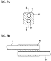
- the heat may be transferred from the first heat transfer unit 10 to the second heat transfer unit 20 by a block-shaped first interface plate 60.
- two through-holes arranged parallel to each other are provided in the block-shaped first interface plate 60, and the first heat pipe 11 and the second heat pipe 21 are inserted into the two through-holes.
- the condensing portion 11b of the first heat pipe 11 and the evaporating portion 21a of the second heat pipe 21 are inserted into the two through-holes. According to this configuration, an optimum contact area between the first interface plate 60 and the heat pipes 11 and 21 is provided and the heat can be more effectively transmitted from the first heat pipe 11 to the second heat pipe 21 via the first interface plate 60.
- the through-holes provided in the first interface plate 60 can be arranged in different orientation with respect to each other.
- aluminum or the like can be used as a material of the first interface plate 60.
- the in-vehicle battery cooling structure 1 of the present embodiment it is also possible to heat the battery cells 31 instead of cooling the battery cells 31 in a cold district.
- a warmed liquid flows through the flow path of the cold plate 50, and the positions of the evaporating portions and the condensing portions in each heat pipe are interchanged. That is, the heat of the liquid flowing through the cold plate 50 is transferred to the battery cells 31 by the second heat transfer unit 20 and the first heat transfer unit 10 respectively, and the battery cells 31 is warmed by this heat.
- charging/discharging efficiency of lithium ion battery is poor at lower temperatures. Therefore, by warming the battery cells 31 in this manner, it is possible to achieve high performance of the battery cells 31.
- Whether the battery cells 31 are cooled or warmed can be easily switched depending on temperature of the liquid flowing through the cold plate 50 and the temperature of the battery cells 31.
Landscapes
- Engineering & Computer Science (AREA)
- Manufacturing & Machinery (AREA)
- Chemical & Material Sciences (AREA)
- Chemical Kinetics & Catalysis (AREA)
- Electrochemistry (AREA)
- General Chemical & Material Sciences (AREA)
- Secondary Cells (AREA)
- Electric Propulsion And Braking For Vehicles (AREA)
Abstract
Description
- The present invention relates to an in-vehicle battery cooling structure.
- For example, as a cooling structure for cooling a heat source, Japanese Unexamined Patent Application, First Publication No.
2017-33267 - In recent years, vehicles (hereinafter, simply referred to as a "vehicle") that are powered by electric energy such as electric vehicles and hybrid cars are becoming widespread. An in-vehicle battery used in this type of vehicle includes a chargeable/dischargeable battery cell. However, when the battery cell is charged and discharged, heat is generated in the battery cell, and thus a cooling structure for cooling the battery cell is required.
- However, for convenience of space inside the vehicle, the cooling structure for the in-vehicle battery used in this type of vehicle is required to efficiently and safely transfer heat to a position away from the in-vehicle battery and to dissipate the heat.
- The present invention is made in consideration of the above-described circumstances, and an objective thereof is to provide an in-vehicle battery cooling structure capable of efficiently and safely transferring heat of the in-vehicle battery to a position away from the in-vehicle battery and dissipating the heat. There are twofold advantages for proposed heat pipe based cooling system design; firstly heat pipe provides safer system by transferring heat to remote location where it could be dissipated safely using liquid cooling, away from high voltage area, and secondly, passively transferred heat could be utilized remotely for cabin space heating or converted to electric energy.
- In order to achieve the above-described object, according to a first aspect of the present invention, there is provided an in-vehicle battery cooling structure which cools an in-vehicle battery for supplying electric energy to a vehicle, including: a first heat transfer unit which includes a heat absorption plate which is in contact with the in-vehicle battery and at least one first heat pipe which is in contact with the heat absorption plate on a first end portion and; a first interface plate which is in contact with a second end portion of the first heat pipe; a second heat transfer unit which includes at least one second heat pipe which is in contact with the first interface plate on a first end portion and a second interface plate which is in contact with a second end portion of the second heat pipe; and a cold plate which is in contact with the second interface plate, the cold plate including an inlet and an outlet for a coolant.
- According to the in-vehicle battery cooling structure of the above-described aspect, the first heat transfer unit transfers heat of the battery cell from the heat absorption plate to the first interface plate via the first heat pipe. In addition, the second heat transfer unit transfers the heat of the battery cell from the first interface plate to the cold plate via the second heat pipe and the second interface plate. According to the configuration, the heat is efficiently transferred to the cold plate away from the battery cell, and thus, this heat can be dissipated.
- In addition, the heat absorption plate may be positioned between a plurality of battery cells included in the in-vehicle battery.
- In this case, a contact area between the heat absorption plate and the battery cell is optimized, and thus, it is possible to efficiently transmit heat from the battery cell to the heat absorption plate. Accordingly, transfer efficiency of heat performed by the first heat transfer unit is optimized, and it is possible to remove heat efficiently from battery cells with passive means.
- According to the above-described aspect of the present invention, it is possible to provide the in-vehicle battery cooling structure capable of efficiently transferring heat of the in-vehicle battery to a position away from the in-vehicle battery and dissipating the heat.
-
-
FIG. 1 is a perspective view of an in-vehicle battery cooling structure. -
FIG. 2 is a plan view of the in-vehicle battery cooling structure. -
FIG. 3 is a front view of the in-vehicle battery cooling structure. -
FIG. 4 is a perspective view of a first heat transfer element. -
FIG. 5A is an explanatory view of a first interface plate according to a modification example. -
FIG. 5B is a sectional view taken along line B-B ofFIG. 5A . - Hereinafter, a configuration of an in-vehicle battery cooling structure according to the present embodiment will be described with reference to
FIGS. 1 to 5B . - As shown in
FIG. 1 , an in-vehiclebattery cooling structure 1 includes a firstheat transfer unit 10, a secondheat transfer unit 20, afirst interface plate 40, and acold plate 50. - The in-vehicle
battery cooling structure 1 cools an in-vehicle battery 30 which includes a plurality ofbattery cells 31. Thebattery cells 31 are electrically connected to each other in series by connectors (not shown). - Here, in the present embodiment, positional relationships of respective configurations will be described by setting an XYZ orthogonal coordinate system. Hereinafter, an X direction is referred to as a left-right direction, a Y direction is referred to as a front-back direction, and a Z direction is referred to an down-up direction.
- As shown in
FIG. 2 , the in-vehicle battery 30, the firstheat transfer unit 10, thefirst interface plate 40, the secondheat transfer unit 20, and thecold plate 50 are arranged in this order in the left-right direction. - Each of the
battery cells 31 can supply electric energy to a motor of a vehicle and can be charged by regenerative energy or charged externally using electricity from grid. Forbattery cells 31, lithium ion based cells can be used. Eachbattery cell 31 has a plate shape extending in the left-right direction and the down-up direction and thebattery cells 31 are arranged in the front-back direction. Eachbattery cell 31 generates heat during charging and discharging. - As shown in
FIG. 2 , the firstheat transfer unit 10 includes a plurality of firstheat transfer elements 10a. The plurality of firstheat transfer elements 10a are arranged in the front-back direction. InFIG. 4 , one of the firstheat transfer elements 10a is shown. As shown inFIG. 4 , the firstheat transfer element 10a includes at least onefirst heat pipe 11, aheat absorption plate 12, and anattachment plate 13. In this embodiment, each of the firstheat transfer elements 10a includes the plurality of thefirst heat pipes 11 arranged in down-up direction. - The
heat absorption plates 12 and theattachment plates 13 are formed of a metal such as aluminum. Theheat absorption plates 12 are formed in a plate shape extending in the left-right direction and the down-up direction. Theattachment plates 13 are formed in a plate shape extending in the front-back direction and the down-up direction. In each firstheat transfer element 10a, a plurality ofgrooves 12a are formed on theheat absorption plate 12, and a plurality ofgrooves 13a are formed on theattachment plate 13. - As the
first heat pipe 11, for example, a heat pipe in which a wick and a working fluid are contained in a copper pipe can be used. Working fluid could be water or nonconductive liquid. As the nonconductive liquid, hydrofluoroether (for example, NOVEC (registered trademark) 7100 made by 3M Company) or the like can be used. - In each
first heat pipe 11, a first end portion on the in-vehicle battery 30 side functions as an evaporatingportion 11a of the working fluid, and a second end portion on the secondheat transfer unit 20 side functions as acondensing portion 11b. - The evaporating
portion 11a of eachfirst heat pipe 11 is fixed into thegroove 12a of theheat absorption plate 12 in a flattened state. The condensingportion 11b of eachfirst heat pipe 11 is fixed into thegroove 13a of theattachment plate 13 in a flattened state. As the fixing method, press-fitting, brazing, soldering, or the like can be used. - The
heat absorption plates 12 are in contact with the evaporatingportions 11a of thefirst heat pipes 11. Theheat absorption plates 12 and the evaporatingportions 11a of thefirst heat pipes 11 are positioned between theadjacent battery cells 31 in the front-back direction and are in contact with the battery cells 31 (refer toFIG. 2 ). Accordingly, if thebattery cells 31 generate heat, theheat absorption plates 12 and the evaporatingportions 11a are heated. - The condensing
portions 11b of thefirst heat pipes 11 are attached to thefirst interface plate 40 via theattachment plates 13. - As shown in
FIG. 2 , in a plan view, eachfirst heat pipe 11 is formed in an approximately L shape in which the evaporatingportion 11a extends in the left-right direction and thecondensing portion 11b extends in the front-back direction. A middle portion of thefirst heat pipe 11 is curved so that thefirst heat pipe 11 extends in the left-right direction and the front-back direction. - In addition, the in-vehicle
battery cooling structure 1 of the present embodiment includes a plurality of firstheat transfer elements 10a. Theheat absorption plate 12 and the evaporatingportions 11a of each firstheat transfer element 10a are disposed between thebattery cells 31 or at both end portions of the in-vehicle battery 30 in the front-back direction. - Moreover, the
first heat pipes 11 of the one firstheat transfer element 10a are disposed at positions different from the otherfirst heat pipes 11 of the adjacentheat transfer element 10a in the down-up direction such that the condensingportions 11b of thefirst heat pipes 11 do not interfere with each other. - As shown in
FIG. 2 , the secondheat transfer unit 20 includes a plurality ofsecond heat pipes 21 and asecond interface plate 22. - Similarly to the
first heat pipes 11, eachsecond heat pipe 21 includes a copper pipe in which the wick and the working fluid are contained. In eachsecond heat pipe 21, a first end portion on thefirst interface plate 40 side functions as an evaporatingportion 21a, and a second end portion on thesecond interface plate 22 viacold plate 50 side functions as a condensingportion 21b. - In a front view as shown in
FIG. 3 , in eachsecond heat pipe 21, the evaporatingportion 21a and the condensingportion 21b extend in the down-up direction and a portion therebetween extends in the left-right direction. Accordingly, eachsecond heat pipe 21 is formed in an approximately U shape in a front view. - As shown in
FIGS. 2 and3 , each of thefirst interface plate 40 and thesecond interface plate 22 is formed in a plate shape extending in the front-back direction and the down-up direction. Thefirst interface plate 40 and thesecond interface plate 22 are formed of a metal such as aluminum. - A plurality of
grooves 40a extending in the down-up direction are formed on a surface of thefirst interface plate 40 on the evaporatingportion 21a side. The evaporatingportion 21a of eachsecond heat pipe 21 is fixed inside thegroove 40a of thefirst interface plate 40. - A plurality of
grooves 22a extending in the down-up direction are formed on a surface of thesecond interface plate 22 on thesecond heat pipe 21 side. The condensingportion 21b of eachsecond heat pipe 21 is fixed inside thegroove 22a of thesecond interface plate 22. - As the fixing method, press-fitting, brazing, soldering, or the like can be used.
- The
cold plate 50 is in contact with thesecond interface plate 22 of the secondheat transfer unit 20. Thecold plate 50 is formed in a plate shape extending in a front-back direction and the down-up direction. - The
cold plate 50 includes aninlet 51 of a coolant, anoutlet 52 of the coolant, and a flow path (not shown) of the coolant. Thecold plate 50 is mainly formed of a metal such as aluminum and the flow path is provided inside thecold plate 50. Theinlet 51 and theoutlet 52 are connected to each other by the flow path. The flow path may meander in thecold plate 50 in order to efficiently transfer heat from thecold plate 50 to the coolant. The flow path and the inlet/outlet cold plate 50 are interchangeable. - The
inlet 51 and theoutlet 52 are provided on a surface of thecold plate 50 opposite to the secondheat transfer unit 20. The coolant flows from theinlet 51 into thecold plate 50 by a pump (not shown) or the like, passes through the flow path in thecold plate 50, and flows out from theoutlet 52. While the coolant flows through the flow path in thecold plate 50, the temperature of the coolant increases by heat received from the secondheat transfer unit 20. - Next, an operation of the in-vehicle
battery cooling structure 1 having the above configuration will be described. - In the first
heat transfer unit 10, theheat absorption plates 12 and the evaporatingportions 11a of thefirst heat pipes 11 are in contact with thebattery cells 31. Accordingly, if thebattery cells 31 generate heat according to the charging and discharging process, theheat absorption plates 12 and the evaporatingportions 11a are heated. In the evaporatingportions 11a, the working fluid in thefirst heat pipes 11 are evaporated by heat received via theheat absorption plates 12 or heat received directly from thebattery cells 31 by thefirst heat pipes 11. The evaporated working fluid passes through thefirst heat pipes 11, flows to the condensingportions 11b of thefirst heat pipes 11, and transfers the heat to thefirst interface plate 40. Accordingly, the working fluid in vapor phase is cooled by the condensingportions 11b resulting in phase change back from vapor to liquid. The condensed working fluid flows to the evaporatingportions 11a again by a capillary force generated by pores of the wick in thefirst heat pipes 11. - According to the above-described operation, the first
heat transfer unit 10 can continuously transfer heat from thebattery cells 31 to thefirst interface plate 40. Accordingly, thefirst interface plate 40 is heated by the operation of the firstheat transfer unit 10. - In the second
heat transfer unit 20, the evaporatingportion 21a of eachsecond heat pipe 21 comes into close contact with thegroove 40a of thefirst interface plate 40. Accordingly, if thefirst interface plate 40 is heated by the firstheat transfer unit 10, the evaporatingportions 21a are heated. In the evaporatingportions 21a, the working fluid in thesecond heat pipes 21 is evaporated by the heat received from thefirst interface plate 40. The evaporated working fluid passes through thesecond heat pipes 21, flows to the condensingportions 21b of thesecond heat pipes 21, and transfers the heat to thesecond interface plate 22. Thesecond interface plate 22 is in contact with thecold plate 50, and thus, thesecond interface plate 22 is cooled by the coolant flowing through thecold plate 50. Accordingly, the working fluid in vapor phase is condensed back to liquid in the condensingportions 21b of thesecond heat pipes 21. The condensed working fluid flows to the evaporatingportions 21a again by a capillary force generated by pores of the wick in thesecond heat pipes 21. - According to the above-described operation, the second
heat transfer unit 20 can continuously transfer heat from thefirst interface plate 40 to thecold plate 50 so as to dissipate the heat. - As described above, in the in-vehicle
battery cooling structure 1 of the present embodiment, the firstheat transfer unit 10 and the secondheat transfer unit 20 can continuously transfer the heat to thecold plate 50 located remotely from the in-vehicle battery 30 so as to dissipate waste heat generated bybattery cells 31. Accordingly, it is possible to efficiently cool thebattery cells 31 using in-vehiclebattery cooling structure 1. - In addition, the
heat absorption plates 12 and the evaporatingportions 11a of thefirst heat pipes 11 are positioned between thebattery cells 31. In this manner, it is possible to channel heat in best possible way between theheat absorption plates 12 or the evaporatingportions 11a and thebattery cells 31. According to this configuration, heat transfer efficiency of the firstheat transfer unit 10 is optimum and this configuration provides most efficient cooling structure ofbattery cells 31. - In addition, a technical scope of the present invention is not limited to the above-described embodiment, and various modifications can be applied to the present invention within a scope that does not depart from the gist of the present invention.
- For example, in the above-described embodiment, the heat is transferred from the first
heat transfer unit 10 to the secondheat transfer unit 20 via a plate-shapedfirst interface plate 40. However, the shape of the first interface plate can be appropriately changed. For example, as shown inFIGS. 5A and 5B , the heat may be transferred from the firstheat transfer unit 10 to the secondheat transfer unit 20 by a block-shapedfirst interface plate 60. In the example ofFIGS. 5A and 5B , two through-holes arranged parallel to each other are provided in the block-shapedfirst interface plate 60, and thefirst heat pipe 11 and thesecond heat pipe 21 are inserted into the two through-holes. The condensingportion 11b of thefirst heat pipe 11 and the evaporatingportion 21a of thesecond heat pipe 21 are inserted into the two through-holes. According to this configuration, an optimum contact area between thefirst interface plate 60 and theheat pipes first heat pipe 11 to thesecond heat pipe 21 via thefirst interface plate 60. In addition, the through-holes provided in thefirst interface plate 60 can be arranged in different orientation with respect to each other. As a material of thefirst interface plate 60, aluminum or the like can be used. - Additionally, according to the in-vehicle
battery cooling structure 1 of the present embodiment, it is also possible to heat thebattery cells 31 instead of cooling thebattery cells 31 in a cold district. In this case, a warmed liquid flows through the flow path of thecold plate 50, and the positions of the evaporating portions and the condensing portions in each heat pipe are interchanged. That is, the heat of the liquid flowing through thecold plate 50 is transferred to thebattery cells 31 by the secondheat transfer unit 20 and the firstheat transfer unit 10 respectively, and thebattery cells 31 is warmed by this heat. As charging/discharging efficiency of lithium ion battery is poor at lower temperatures. Therefore, by warming thebattery cells 31 in this manner, it is possible to achieve high performance of thebattery cells 31. - Whether the
battery cells 31 are cooled or warmed can be easily switched depending on temperature of the liquid flowing through thecold plate 50 and the temperature of thebattery cells 31. - While preferred embodiments of the invention have been described and illustrated above, it should be understood that these are exemplary of the invention and are not to be considered as limiting. Additions, omissions, substitutions, and other modifications can be made without departing from the scope of the present invention. Accordingly, the invention is not to be considered as being limited by the foregoing description, and is only limited by the scope of the appended claims.
-
- 1...in-vehicle battery cooling structure, 10...first heat transfer unit, 11...first heat pipe, 12...heat absorption plate, 20...second heat transfer unit, 21...second heat pipe, 22...second interface plate, 30...in-vehicle battery, 31...battery cell, 40, 60...first interface plate, 50...cold plate, 51...inlet, 52...outlet
Claims (2)
- An in-vehicle battery cooling structure which cools an in-vehicle battery for supplying electric energy to a vehicle, the in-vehicle battery cooling structure comprising:a first heat transfer unit which includes a heat absorption plate which is in contact with the in-vehicle battery and at least one first heat pipe which is in contact with the heat absorption plate on a first end portion and;a first interface plate which is in contact with a second end portion of the first heat pipe;a second heat transfer unit which includes at least one second heat pipe which is in contact with the first interface plate on a first end portion and a second interface plate which is in contact with a second end portion of the second heat pipe; anda cold plate which is in contact with the second interface plate, the cold plate including an inlet and an outlet for a coolant.
- The in-vehicle battery cooling structure according to claim 1,
wherein the heat absorption plate is positioned between a plurality of battery cells included in the in-vehicle battery.
Applications Claiming Priority (1)
| Application Number | Priority Date | Filing Date | Title |
|---|---|---|---|
| JP2017083722A JP2018181761A (en) | 2017-04-20 | 2017-04-20 | Automotive battery cooling structure |
Publications (1)
| Publication Number | Publication Date |
|---|---|
| EP3392956A1 true EP3392956A1 (en) | 2018-10-24 |
Family
ID=62017229
Family Applications (1)
| Application Number | Title | Priority Date | Filing Date |
|---|---|---|---|
| EP18167741.0A Withdrawn EP3392956A1 (en) | 2017-04-20 | 2018-04-17 | Cooling system comprising two heatpipes connected connected in series |
Country Status (2)
| Country | Link |
|---|---|
| EP (1) | EP3392956A1 (en) |
| JP (1) | JP2018181761A (en) |
Cited By (1)
| Publication number | Priority date | Publication date | Assignee | Title |
|---|---|---|---|---|
| CN109841921A (en) * | 2019-03-19 | 2019-06-04 | 华南理工大学 | A kind of power battery liquid cooling apparatus and its working method |
Families Citing this family (3)
| Publication number | Priority date | Publication date | Assignee | Title |
|---|---|---|---|---|
| JP2020101345A (en) * | 2018-12-25 | 2020-07-02 | 株式会社フジクラ | In-vehicle battery cooling structure |
| WO2021071212A1 (en) * | 2019-10-07 | 2021-04-15 | 에스케이씨 주식회사 | Wireless charging device and mobile means including same |
| KR20240028780A (en) * | 2022-08-25 | 2024-03-05 | 주식회사 엘지에너지솔루션 | Pipe for transporting fluid |
Citations (4)
| Publication number | Priority date | Publication date | Assignee | Title |
|---|---|---|---|---|
| KR20060086120A (en) * | 2005-01-26 | 2006-07-31 | 삼성에스디아이 주식회사 | Secondary battery module |
| US20150194714A1 (en) * | 2012-07-19 | 2015-07-09 | Sk Innovation Co., Ltd. | Battery module assembly |
| US20170005380A1 (en) * | 2015-06-30 | 2017-01-05 | Faraday&Future Inc. | Heat Pipe For Vehicle Energy-Storage Systems |
| JP2017033267A (en) | 2015-07-31 | 2017-02-09 | 株式会社フジクラ | Water-cooling structure of server board |
Family Cites Families (2)
| Publication number | Priority date | Publication date | Assignee | Title |
|---|---|---|---|---|
| CN103283063B (en) * | 2010-12-28 | 2016-02-24 | 株式会社Lg化学 | Battery module receiving device, battery module thermostat, and power storage system including the same |
| JP6754352B2 (en) * | 2015-02-18 | 2020-09-09 | 古河電気工業株式会社 | Battery temperature control device and battery temperature control system |
-
2017
- 2017-04-20 JP JP2017083722A patent/JP2018181761A/en active Pending
-
2018
- 2018-04-17 EP EP18167741.0A patent/EP3392956A1/en not_active Withdrawn
Patent Citations (4)
| Publication number | Priority date | Publication date | Assignee | Title |
|---|---|---|---|---|
| KR20060086120A (en) * | 2005-01-26 | 2006-07-31 | 삼성에스디아이 주식회사 | Secondary battery module |
| US20150194714A1 (en) * | 2012-07-19 | 2015-07-09 | Sk Innovation Co., Ltd. | Battery module assembly |
| US20170005380A1 (en) * | 2015-06-30 | 2017-01-05 | Faraday&Future Inc. | Heat Pipe For Vehicle Energy-Storage Systems |
| JP2017033267A (en) | 2015-07-31 | 2017-02-09 | 株式会社フジクラ | Water-cooling structure of server board |
Non-Patent Citations (1)
| Title |
|---|
| ANDREY BELYAEV ET AL: "BNL-105291-2014-CP Investigation of Heat Pipe Cooling Of LI-ION Batteries", INTERNATIONAL MECHANICAL ENGINEERING CONGRESS & EXPOSITION, 14 November 2014 (2014-11-14), XP055768366, Retrieved from the Internet <URL:https://www.bnl.gov/isd/documents/86095.pdf> * |
Cited By (1)
| Publication number | Priority date | Publication date | Assignee | Title |
|---|---|---|---|---|
| CN109841921A (en) * | 2019-03-19 | 2019-06-04 | 华南理工大学 | A kind of power battery liquid cooling apparatus and its working method |
Also Published As
| Publication number | Publication date |
|---|---|
| JP2018181761A (en) | 2018-11-15 |
Similar Documents
| Publication | Publication Date | Title |
|---|---|---|
| EP2814089B1 (en) | Battery pack with a bus bar having novel structure | |
| EP3293792B1 (en) | Battery system | |
| KR102253247B1 (en) | Thermoelectric-based thermal management system | |
| EP3392956A1 (en) | Cooling system comprising two heatpipes connected connected in series | |
| CN107112611B (en) | Battery temperature regulating device and battery temperature regulating system | |
| JP5757502B2 (en) | Battery temperature control unit and battery temperature control device | |
| EP3392955B1 (en) | Cooling system including heat pipes | |
| CN103959508B (en) | There is the battery system of the temperature control body comprising homoiothermic passage and bypass and comprise the motor vehicles of battery system | |
| US9509018B2 (en) | Expanded battery cooling fin | |
| CN109659643B (en) | Battery cell module, secondary battery pack, and motor vehicle | |
| KR20170057328A (en) | Graphite thermoelectric and/or resistive thermal management systems and methods | |
| JP2009147187A (en) | Heating element cooling device | |
| JP3159901U (en) | Battery heat dissipation module for car | |
| JP2009152440A (en) | Temperature regulator for heating element | |
| CN104564298A (en) | Cooling system for an electric vehicle and method for producing a cooling system | |
| CN108886189A (en) | Battery pack temperature control, power supply system | |
| JP2012501058A (en) | Battery module | |
| CN113544897A (en) | Cooling system for cooling battery module, high-voltage battery and motor vehicle | |
| US9865886B2 (en) | Coolable battery system, method for cooling a battery and automobile comprising a coolable battery system | |
| EP2884577A1 (en) | Temperature adjustment device and battery equipped with same | |
| CN106463798B (en) | Energy storage device, temperature control device of vehicle and motor vehicle | |
| JP7562244B2 (en) | Techniques for heating traction energy storage devices | |
| US20260081255A1 (en) | Traction battery which can be temperature-controlled by means of a fluid | |
| KR101670021B1 (en) | The battery module Heating units | |
| KR20140034362A (en) | Secondary battery module having heat exchanging device and heat exchanging method of the same |
Legal Events
| Date | Code | Title | Description |
|---|---|---|---|
| PUAI | Public reference made under article 153(3) epc to a published international application that has entered the european phase |
Free format text: ORIGINAL CODE: 0009012 |
|
| STAA | Information on the status of an ep patent application or granted ep patent |
Free format text: STATUS: REQUEST FOR EXAMINATION WAS MADE |
|
| 17P | Request for examination filed |
Effective date: 20180417 |
|
| AK | Designated contracting states |
Kind code of ref document: A1 Designated state(s): AL AT BE BG CH CY CZ DE DK EE ES FI FR GB GR HR HU IE IS IT LI LT LU LV MC MK MT NL NO PL PT RO RS SE SI SK SM TR |
|
| AX | Request for extension of the european patent |
Extension state: BA ME |
|
| RBV | Designated contracting states (corrected) |
Designated state(s): AL AT BE BG CH CY CZ DE DK EE ES FI FR GB GR HR HU IE IS IT LI LT LU LV MC MK MT NL NO PL PT RO RS SE SI SK SM TR |
|
| R17P | Request for examination filed (corrected) |
Effective date: 20180417 |
|
| STAA | Information on the status of an ep patent application or granted ep patent |
Free format text: STATUS: EXAMINATION IS IN PROGRESS |
|
| STAA | Information on the status of an ep patent application or granted ep patent |
Free format text: STATUS: THE APPLICATION HAS BEEN WITHDRAWN |
|
| 17Q | First examination report despatched |
Effective date: 20210129 |
|
| 18W | Application withdrawn |
Effective date: 20210201 |