EP3392670A1 - A method and system for spatial modelling of an interior of a vehicle - Google Patents
A method and system for spatial modelling of an interior of a vehicle Download PDFInfo
- Publication number
- EP3392670A1 EP3392670A1 EP17167198.5A EP17167198A EP3392670A1 EP 3392670 A1 EP3392670 A1 EP 3392670A1 EP 17167198 A EP17167198 A EP 17167198A EP 3392670 A1 EP3392670 A1 EP 3392670A1
- Authority
- EP
- European Patent Office
- Prior art keywords
- vehicle
- signals
- interior
- transmitters
- determining
- Prior art date
- Legal status (The legal status is an assumption and is not a legal conclusion. Google has not performed a legal analysis and makes no representation as to the accuracy of the status listed.)
- Granted
Links
Images

Classifications
-
- G—PHYSICS
- G01—MEASURING; TESTING
- G01S—RADIO DIRECTION-FINDING; RADIO NAVIGATION; DETERMINING DISTANCE OR VELOCITY BY USE OF RADIO WAVES; LOCATING OR PRESENCE-DETECTING BY USE OF THE REFLECTION OR RERADIATION OF RADIO WAVES; ANALOGOUS ARRANGEMENTS USING OTHER WAVES
- G01S15/00—Systems using the reflection or reradiation of acoustic waves, e.g. sonar systems
- G01S15/88—Sonar systems specially adapted for specific applications
- G01S15/89—Sonar systems specially adapted for specific applications for mapping or imaging
-
- G—PHYSICS
- G01—MEASURING; TESTING
- G01S—RADIO DIRECTION-FINDING; RADIO NAVIGATION; DETERMINING DISTANCE OR VELOCITY BY USE OF RADIO WAVES; LOCATING OR PRESENCE-DETECTING BY USE OF THE REFLECTION OR RERADIATION OF RADIO WAVES; ANALOGOUS ARRANGEMENTS USING OTHER WAVES
- G01S13/00—Systems using the reflection or reradiation of radio waves, e.g. radar systems; Analogous systems using reflection or reradiation of waves whose nature or wavelength is irrelevant or unspecified
- G01S13/88—Radar or analogous systems specially adapted for specific applications
- G01S13/91—Radar or analogous systems specially adapted for specific applications for traffic control
-
- B—PERFORMING OPERATIONS; TRANSPORTING
- B60—VEHICLES IN GENERAL
- B60N—SEATS SPECIALLY ADAPTED FOR VEHICLES; VEHICLE PASSENGER ACCOMMODATION NOT OTHERWISE PROVIDED FOR
- B60N2/00—Seats specially adapted for vehicles; Arrangement or mounting of seats in vehicles
- B60N2/002—Seats provided with an occupancy detection means mounted therein or thereon
- B60N2/0021—Seats provided with an occupancy detection means mounted therein or thereon characterised by the type of sensor or measurement
- B60N2/0024—Seats provided with an occupancy detection means mounted therein or thereon characterised by the type of sensor or measurement for identifying, categorising or investigation of the occupant or object on the seat
- B60N2/0026—Seats provided with an occupancy detection means mounted therein or thereon characterised by the type of sensor or measurement for identifying, categorising or investigation of the occupant or object on the seat for distinguishing between humans, animals or objects
-
- B—PERFORMING OPERATIONS; TRANSPORTING
- B60—VEHICLES IN GENERAL
- B60Q—ARRANGEMENT OF SIGNALLING OR LIGHTING DEVICES, THE MOUNTING OR SUPPORTING THEREOF OR CIRCUITS THEREFOR, FOR VEHICLES IN GENERAL
- B60Q5/00—Arrangement or adaptation of acoustic signal devices
-
- G—PHYSICS
- G01—MEASURING; TESTING
- G01S—RADIO DIRECTION-FINDING; RADIO NAVIGATION; DETERMINING DISTANCE OR VELOCITY BY USE OF RADIO WAVES; LOCATING OR PRESENCE-DETECTING BY USE OF THE REFLECTION OR RERADIATION OF RADIO WAVES; ANALOGOUS ARRANGEMENTS USING OTHER WAVES
- G01S13/00—Systems using the reflection or reradiation of radio waves, e.g. radar systems; Analogous systems using reflection or reradiation of waves whose nature or wavelength is irrelevant or unspecified
- G01S13/02—Systems using reflection of radio waves, e.g. primary radar systems; Analogous systems
- G01S13/50—Systems of measurement based on relative movement of target
- G01S13/52—Discriminating between fixed and moving objects or between objects moving at different speeds
- G01S13/56—Discriminating between fixed and moving objects or between objects moving at different speeds for presence detection
-
- G—PHYSICS
- G01—MEASURING; TESTING
- G01S—RADIO DIRECTION-FINDING; RADIO NAVIGATION; DETERMINING DISTANCE OR VELOCITY BY USE OF RADIO WAVES; LOCATING OR PRESENCE-DETECTING BY USE OF THE REFLECTION OR RERADIATION OF RADIO WAVES; ANALOGOUS ARRANGEMENTS USING OTHER WAVES
- G01S13/00—Systems using the reflection or reradiation of radio waves, e.g. radar systems; Analogous systems using reflection or reradiation of waves whose nature or wavelength is irrelevant or unspecified
- G01S13/87—Combinations of radar systems, e.g. primary radar and secondary radar
-
- G—PHYSICS
- G01—MEASURING; TESTING
- G01S—RADIO DIRECTION-FINDING; RADIO NAVIGATION; DETERMINING DISTANCE OR VELOCITY BY USE OF RADIO WAVES; LOCATING OR PRESENCE-DETECTING BY USE OF THE REFLECTION OR RERADIATION OF RADIO WAVES; ANALOGOUS ARRANGEMENTS USING OTHER WAVES
- G01S13/00—Systems using the reflection or reradiation of radio waves, e.g. radar systems; Analogous systems using reflection or reradiation of waves whose nature or wavelength is irrelevant or unspecified
- G01S13/88—Radar or analogous systems specially adapted for specific applications
- G01S13/89—Radar or analogous systems specially adapted for specific applications for mapping or imaging
-
- G—PHYSICS
- G01—MEASURING; TESTING
- G01S—RADIO DIRECTION-FINDING; RADIO NAVIGATION; DETERMINING DISTANCE OR VELOCITY BY USE OF RADIO WAVES; LOCATING OR PRESENCE-DETECTING BY USE OF THE REFLECTION OR RERADIATION OF RADIO WAVES; ANALOGOUS ARRANGEMENTS USING OTHER WAVES
- G01S15/00—Systems using the reflection or reradiation of acoustic waves, e.g. sonar systems
- G01S15/003—Bistatic sonar systems; Multistatic sonar systems
-
- G—PHYSICS
- G01—MEASURING; TESTING
- G01S—RADIO DIRECTION-FINDING; RADIO NAVIGATION; DETERMINING DISTANCE OR VELOCITY BY USE OF RADIO WAVES; LOCATING OR PRESENCE-DETECTING BY USE OF THE REFLECTION OR RERADIATION OF RADIO WAVES; ANALOGOUS ARRANGEMENTS USING OTHER WAVES
- G01S15/00—Systems using the reflection or reradiation of acoustic waves, e.g. sonar systems
- G01S15/02—Systems using the reflection or reradiation of acoustic waves, e.g. sonar systems using reflection of acoustic waves
- G01S15/06—Systems determining the position data of a target
- G01S15/42—Simultaneous measurement of distance and other co-ordinates
-
- G—PHYSICS
- G01—MEASURING; TESTING
- G01S—RADIO DIRECTION-FINDING; RADIO NAVIGATION; DETERMINING DISTANCE OR VELOCITY BY USE OF RADIO WAVES; LOCATING OR PRESENCE-DETECTING BY USE OF THE REFLECTION OR RERADIATION OF RADIO WAVES; ANALOGOUS ARRANGEMENTS USING OTHER WAVES
- G01S15/00—Systems using the reflection or reradiation of acoustic waves, e.g. sonar systems
- G01S15/02—Systems using the reflection or reradiation of acoustic waves, e.g. sonar systems using reflection of acoustic waves
- G01S15/50—Systems of measurement, based on relative movement of the target
- G01S15/52—Discriminating between fixed and moving objects or between objects moving at different speeds
- G01S15/523—Discriminating between fixed and moving objects or between objects moving at different speeds for presence detection
-
- G—PHYSICS
- G01—MEASURING; TESTING
- G01S—RADIO DIRECTION-FINDING; RADIO NAVIGATION; DETERMINING DISTANCE OR VELOCITY BY USE OF RADIO WAVES; LOCATING OR PRESENCE-DETECTING BY USE OF THE REFLECTION OR RERADIATION OF RADIO WAVES; ANALOGOUS ARRANGEMENTS USING OTHER WAVES
- G01S15/00—Systems using the reflection or reradiation of acoustic waves, e.g. sonar systems
- G01S15/87—Combinations of sonar systems
-
- G—PHYSICS
- G01—MEASURING; TESTING
- G01S—RADIO DIRECTION-FINDING; RADIO NAVIGATION; DETERMINING DISTANCE OR VELOCITY BY USE OF RADIO WAVES; LOCATING OR PRESENCE-DETECTING BY USE OF THE REFLECTION OR RERADIATION OF RADIO WAVES; ANALOGOUS ARRANGEMENTS USING OTHER WAVES
- G01S7/00—Details of systems according to groups G01S13/00, G01S15/00, G01S17/00
- G01S7/52—Details of systems according to groups G01S13/00, G01S15/00, G01S17/00 of systems according to group G01S15/00
- G01S7/539—Details of systems according to groups G01S13/00, G01S15/00, G01S17/00 of systems according to group G01S15/00 using analysis of echo signal for target characterisation; Target signature; Target cross-section
-
- G—PHYSICS
- G01—MEASURING; TESTING
- G01S—RADIO DIRECTION-FINDING; RADIO NAVIGATION; DETERMINING DISTANCE OR VELOCITY BY USE OF RADIO WAVES; LOCATING OR PRESENCE-DETECTING BY USE OF THE REFLECTION OR RERADIATION OF RADIO WAVES; ANALOGOUS ARRANGEMENTS USING OTHER WAVES
- G01S7/00—Details of systems according to groups G01S13/00, G01S15/00, G01S17/00
- G01S7/52—Details of systems according to groups G01S13/00, G01S15/00, G01S17/00 of systems according to group G01S15/00
- G01S7/54—Details of systems according to groups G01S13/00, G01S15/00, G01S17/00 of systems according to group G01S15/00 with receivers spaced apart
-
- G—PHYSICS
- G06—COMPUTING OR CALCULATING; COUNTING
- G06N—COMPUTING ARRANGEMENTS BASED ON SPECIFIC COMPUTATIONAL MODELS
- G06N3/00—Computing arrangements based on biological models
- G06N3/02—Neural networks
-
- G—PHYSICS
- G06—COMPUTING OR CALCULATING; COUNTING
- G06T—IMAGE DATA PROCESSING OR GENERATION, IN GENERAL
- G06T17/00—Three-dimensional [3D] modelling for computer graphics
-
- B—PERFORMING OPERATIONS; TRANSPORTING
- B60—VEHICLES IN GENERAL
- B60N—SEATS SPECIALLY ADAPTED FOR VEHICLES; VEHICLE PASSENGER ACCOMMODATION NOT OTHERWISE PROVIDED FOR
- B60N2210/00—Sensor types, e.g. for passenger detection systems or for controlling seats
- B60N2210/10—Field detection presence sensors
- B60N2210/16—Electromagnetic waves
- B60N2210/20—Radar
-
- B—PERFORMING OPERATIONS; TRANSPORTING
- B60—VEHICLES IN GENERAL
- B60N—SEATS SPECIALLY ADAPTED FOR VEHICLES; VEHICLE PASSENGER ACCOMMODATION NOT OTHERWISE PROVIDED FOR
- B60N2230/00—Communication or electronic aspects
- B60N2230/20—Wireless data transmission
Definitions
- the present invention relates to a method and a system for determining a spatial model of an interior of a vehicle, and in particular for determining the location of objects in the vehicle.
- a system for detecting the presence of a driver and passengers in a vehicle. Such a system may for example detect if a specific seat is occupied, and provide a seat belt warning if no seat belt is used in the occupied seat.
- driver monitoring systems for example for detecting driver drowsiness, if the driver is incapacitated or ill, and also to for aiding the driver by directing the attention of the driver to relevant events.
- driver monitoring systems for example for detecting driver drowsiness, if the driver is incapacitated or ill, and also to for aiding the driver by directing the attention of the driver to relevant events.
- an object detection system may advantageously be used to warn an operator of the vehicle in case the doors are locked and the car is to be abandoned, while a person or animal which may have been forgotten are still in the car, which may be dangerous on hot, sunny days.
- an object of the present invention to provide an improved method and system for object detection and identification in a vehicle.
- an object of the present invention is to provide a method and system for spatial modelling of the interior of the vehicle.
- a method for spatial modelling of an interior of a vehicle comprising: transmitting a wireless signal, from each of a plurality of transmitters, each transmitter having a known location in the vehicle; receiving, by a plurality of receivers, a plurality of reflection signals having been reflected in the interior of the vehicle, each receiver having a known location in the vehicle; for the received reflection signals, determining a source data set by determining multipath propagation components, Doppler shifts, phase shifts and time differences of the received reflection signals; and determining a spatial model of at least a portion of the vehicle interior by applying a computer vision algorithm on the source data set.
- the transmitter is configured to transmit one or more wireless signals into the interior of the vehicle, where the wireless signals may be radio signals or acoustic signals. It should be understood that a plurality of transmitters may be arranged to transmit signals in various directions, and that the specific configuration and placement of transmitters and receivers may be determined for each specific vehicle interior, depending on the design of the interior.
- the signals are reflected in various surfaces and objects in the interiors before reaching the receivers.
- the transmitted signals may have been reflected one or more times in objects in the vehicle.
- the received reflected signals can be distinguished from any transmitted signals directly reaching a receiver without reflection based on e.g. the signal amplitude and phase. It is also assumed that the empty interior of the vehicle is known such that the algorithm can determine deviations from the empty interior.
- determining the source data set should be interpreted to include all the information gathering and signal processing required as input to the computer vision algorithm.
- the source data set is determined based in the received reflected signals and with knowledge of the properties of the transmitted signals.
- the spatial model is a three dimensional model of the vehicle interior. It is also possible to determine the model for only part of the interior.
- the transmitter and receiver arrangement may for example be adapted for only determining a model of comprising the front seats of the vehicle, or the algorithm may be configured to select to only model a particular volume of interest.
- the present invention is based on the realization that algorithms previously used for computer vision may be applied also for wireless signals in order to form a three dimensional model based on reflected signals.
- the described method provides a detailed description of the vehicle interior, without the need for cameras and related image analysis circuitry, which can simplify and thereby increase the availability of spatial modelling such systems in vehicles.
- graphics processing units and the like may be used also for spatial modelling.
- the spatial model may be used to increase the efficiency of various safety features and also to warn for potentially dangerous situations arising from the presence of objects in the interior of the vehicle.
- applying the computer vision algorithm comprises performing generalized cross correlation with phase transform, GCC-PHAT, which is a method for computing time delays between signals and reference signals where the signals may have multiple channels.
- the method may further comprise explicitly tracking the multi-path components.
- the multi path components are then used in the spatial modelling.
- the method may further comprise identifying and categorizing objects in the vehicle.
- the method may for example comprise identifying specific objects, such as persons in the vehicle.
- the identified objects may also be defined in terms of different categories such as animate and inanimate objects.
- the objects may be defined and categorized based on shape, size, location etc.
- applying one or more computer vision algorithms may advantageously comprise employing a neural network for analyzing the source data set.
- a neural network can be used for classification and also for forming the spatial model.
- the computer vision algorithm may consist of a signal processing part and a geometry estimation part where the resulting spatial model is formed.
- a neural network may be trained, in a similar manner as for images when training a neural network for image recognition.
- the advantages with a neural network are thus the same as for image recognition. Either a neural network is trained on the signal processed data or specific algorithms can be used, advantageously both algorithms and a neural network is used in combination.
- the method may advantageously comprise identifying locations of vehicle occupants.
- safety features and other functions in the vehicle can be adapted based on if a seat is occupied or not. It is also possible to detect and warn if a vehicle occupant is in an unsafe location in the vehicle.
- the transmitted signals may be audio signals having a frequency in the range of 20-30 kHz or in the range of 40-50 kHz. Audio signals having a frequency in the range of 20-30 kHz may advantageously be used since they can be emitted by speakers in an existing entertainment system of the vehicle, thereby not requiring additional dedicated transmitters for transmitting the signals. However, audio signals in the low ultrasound range, i.e. around 20Hz may be detected by some animals and may not be desirable for that reason. Thereby, audio signals having a frequency above 40kHz may be advantageously used. It should however be understood that signals of other frequencies also may be used.
- the transmitted signals may be radio signals having a frequency of 2.5GHz or 5GHz.
- an existing WiFi transmitter of the vehicle typically operating at one of the aforementioned frequencies may be used. It may also be advantageous to employ a combination of audio and radio signals to derive additional information for use by the computer vision algorithm.
- transmitting a wireless signal may comprise transmitting a plurality of separate signals having different properties. Accordingly, both audio and radio signals may be used, and the transmitted signals may have different amplitude or modulation in order to acquire more detailed source data for use by the computer vision algorithm. For example, the transmitted signals may have overlapping or nonoverlapping bandwidths, and the signals may be sent sequentially or in parallel. It is also possible that one transmitter sends different signals sequentially, or that specific transmitters are adapted to only transmit a particular signal.
- method may further comprise determining a temperature and airflow properties in the vehicle, and wherein the spatial model is determined based on the determined temperature and airflow properties.
- the propagation properties of wireless signals, and of audio signals in particular, depend on the properties of the medium in which they propagate. Thereby, by taking the temperature and airflow of the vehicle interior into account when forming the spatial model an increased accuracy can be achieved. It is also possible to measure and include additional environmental parameters such as humidity. Moreover, the described environmental parameters may be measured at several different locations in the vehicle such that the propagation properties in the vehicle can be determined with an even higher accuracy in case there are noticeable variations throughout the vehicle interior. The environmental parameters are mainly important for lower frequencies in the range of audio or ultrasound frequencies.
- the method may comprise identifying an object by comparing the determined spatial model with a predetermined spatial model of an empty vehicle.
- a system for spatial modelling of an interior of a vehicle comprising: a plurality of transmitters at known locations within the vehicle, each transmitter being configured to transmit a wireless signal; a plurality of receivers at known locations within the vehicle, each receiver being arranged and configured to receive a plurality of reflection signals having been reflected in the interior of the vehicle; a spatial modelling control unit connected to the transmitters and receivers and configured to, for the received reflection signals, determining a source data set by determining multipath propagation components, Doppler shifts, phase shifts and time differences of the received reflection signals, and to determine a spatial model of at least a portion of the vehicle interior by applying a computer vision algorithm on the source data set.
- the transmitters may comprise speakers of an entertainment system of the vehicle or ultrasonic transmitters.
- the transmitters may also be transceivers capable of both transmitting and receiving signals, or the receivers can be arranged separately from the transmitters.
- the transmitters may comprise a WiFi transmitter and receiver of the vehicle.
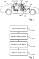
- Fig. 1 schematically illustrates a vehicle comprising a system for spatial modelling of an interior of a vehicle according to an embodiment of the invention.
- the system of Fig. 1 will be described with further reference to the flow chart of Fig. 2 outlining the general steps of a method for spatial modelling of an interior of a vehicle according to an embodiment of the invention.
- the system of Fig. 1 comprises a plurality of transmitters, 102a-c at known locations within the vehicle 100. Each of the transmitters configured to transmit 200 a wireless signal into the vehicle interior.
- the system further comprises a plurality of receivers 104a-c at known locations within the vehicle 100, where each receiver is arranged at a suitable location arranged and configured to receive 202 a plurality of reflection signals having been reflected in the interior of the vehicle.
- the transmitters 102a-c and receivers 104a-c are illustrated as separate units, the transmitters 102a-c and receivers 104a-c may equally well be embodied by transceivers having the capability to both transmit and receive signals.
- the transmitters 102a-c and receivers 104a-c may also be located at a distance from each other, and the number of transmitters may be different from the number of receivers. Accordingly, the specific placement of transmitters and receivers within the vehicle can be assumed to be different for different vehicles and for different applications.
- the system further comprises a spatial modelling control unit 106 connected to the transmitters and receivers.
- the control unit 106 can be considered to control both the transmission of signals as well as the following processing of the received reflected signals.
- the control unit 106 may include a microprocessor, microcontroller, programmable digital signal processor or another programmable device.
- the control unit 106 may also, or instead, include an application specific integrated circuit, a programmable gate array or programmable array logic, a programmable logic device, a digital signal processor or equivalent hardware.
- the processor may further include computer executable code that controls operation of the programmable device.
- control unit 106 may be a specific spatial modelling control unit or it may be a general purpose control unit being part of the vehicle infrastructure.
- the control unit 106 is further configured to, for the received reflection signals, determining a source data set 204 by determining multipath propagation components, Doppler shifts, phase shifts and time differences of the received reflection signals.
- the multipath propagation components describe received reflection signals with respect to multiple reflections, thereby providing additional information for forming the spatial model.
- phase shifts and time differences i.e. differences in a determined time-of-flight, of different reflected signals provide information of the structure and objects of the vehicle interior.
- separating reflected signals from direct signals is performed as part of the analysis of the multipath propagation components, Doppler effects and phase shifts.
- a spatial model of at least a portion of the vehicle interior is determined 206 by applying a computer vision algorithm on the source data set.
- a set of signals used for determining a spatial model may for example comprise short bursts of well-defined frequencies in a sequence of separate signals.
- the preferred signal properties also depend on the sensitivity of receivers, such as how well the receiver can distinguish each frequency and also how well a signal generator may generate and a transmitter can transmit a specific frequency.
- the described method can be seen as consisting of two parts, a signal processing part where the signal characteristics are measured, and a geometry/spatial modeling part where the spatial model is built using Vision Algorithms mentioned in the aforementioned reference.
- a signal processing part where the signal characteristics are measured
- a geometry/spatial modeling part where the spatial model is built using Vision Algorithms mentioned in the aforementioned reference.
- TOA time of arrival
- TDOA time difference of arrival
- Computer vision algorithms and related algorithms suitable for spatial modelling are sometimes referred to as "structure from motion” algorithms.
- Fig. 3 schematically illustrates a system according to an embodiment of the invention where speakers 300a-e of an entertainment system are used as transmitters to transmit an audio signal.
- the speakers may be configured to transmit signals also in the ultrasound frequency range.
- the accuracy of the spatial model is in the range of a few millimeters and for radio signals the accuracy can be even higher.
- the acoustic signals may advantageously be combined with radio signals such as WiFi or Bluetooth signals provided by radio transmitters of the vehicle.
Landscapes
- Engineering & Computer Science (AREA)
- Remote Sensing (AREA)
- Radar, Positioning & Navigation (AREA)
- Physics & Mathematics (AREA)
- General Physics & Mathematics (AREA)
- Computer Networks & Wireless Communication (AREA)
- Acoustics & Sound (AREA)
- Theoretical Computer Science (AREA)
- Mechanical Engineering (AREA)
- Electromagnetism (AREA)
- Software Systems (AREA)
- Transportation (AREA)
- Aviation & Aerospace Engineering (AREA)
- Health & Medical Sciences (AREA)
- Data Mining & Analysis (AREA)
- Life Sciences & Earth Sciences (AREA)
- Artificial Intelligence (AREA)
- Biomedical Technology (AREA)
- Biophysics (AREA)
- Computational Linguistics (AREA)
- Geometry (AREA)
- Evolutionary Computation (AREA)
- General Health & Medical Sciences (AREA)
- Molecular Biology (AREA)
- Computing Systems (AREA)
- General Engineering & Computer Science (AREA)
- Mathematical Physics (AREA)
- Computer Graphics (AREA)
- Measurement Of Velocity Or Position Using Acoustic Or Ultrasonic Waves (AREA)
Abstract
Description
- The present invention relates to a method and a system for determining a spatial model of an interior of a vehicle, and in particular for determining the location of objects in the vehicle.
- Several systems are known for detecting the presence of a driver and passengers in a vehicle. Such a system may for example detect if a specific seat is occupied, and provide a seat belt warning if no seat belt is used in the occupied seat. There are also may different types of driver monitoring systems, for example for detecting driver drowsiness, if the driver is incapacitated or ill, and also to for aiding the driver by directing the attention of the driver to relevant events. However, with the increasing number of safety functions in a vehicle, it is desirable to be able to determine both the presence and the location of many types of objects in a vehicle, other than just the driver and passengers.
- It is furthermore desirable to not only detect but to possibly also identify objects in the car that is not part of the car interior as such. For example persons, animals, or bags and other identifiable objects that may be of interest from a security point of view. The detection of objects can be used to determine whether to deploy airbags or not, which airbags or other safety features to deploy in case of an accident, or to warn if objects are a potential hazard in case of a collision, such as bags and other objects which are placed incorrectly. The object detection system can also be used for detecting persons thereby being part of a driver monitoring system, and also helping to identify not only the driver but also all passengers and their absolute position in the car. Finally, an object detection system may advantageously be used to warn an operator of the vehicle in case the doors are locked and the car is to be abandoned, while a person or animal which may have been forgotten are still in the car, which may be dangerous on hot, sunny days.
- Accordingly, it is desirable to provide an improved system for object detection and identification in the interior of a vehicle.
- In view of above-mentioned and other drawbacks of the prior art, it is an object of the present invention to provide an improved method and system for object detection and identification in a vehicle. In particular, an object of the present invention is to provide a method and system for spatial modelling of the interior of the vehicle.
- According to a first aspect of the invention, there is provided a method for spatial modelling of an interior of a vehicle, the method comprising: transmitting a wireless signal, from each of a plurality of transmitters, each transmitter having a known location in the vehicle; receiving, by a plurality of receivers, a plurality of reflection signals having been reflected in the interior of the vehicle, each receiver having a known location in the vehicle; for the received reflection signals, determining a source data set by determining multipath propagation components, Doppler shifts, phase shifts and time differences of the received reflection signals; and determining a spatial model of at least a portion of the vehicle interior by applying a computer vision algorithm on the source data set.
- The transmitter is configured to transmit one or more wireless signals into the interior of the vehicle, where the wireless signals may be radio signals or acoustic signals. It should be understood that a plurality of transmitters may be arranged to transmit signals in various directions, and that the specific configuration and placement of transmitters and receivers may be determined for each specific vehicle interior, depending on the design of the interior.
- Next, the signals are reflected in various surfaces and objects in the interiors before reaching the receivers. The transmitted signals may have been reflected one or more times in objects in the vehicle. The received reflected signals can be distinguished from any transmitted signals directly reaching a receiver without reflection based on e.g. the signal amplitude and phase. It is also assumed that the empty interior of the vehicle is known such that the algorithm can determine deviations from the empty interior.
- In the present context, determining the source data set should be interpreted to include all the information gathering and signal processing required as input to the computer vision algorithm. The source data set is determined based in the received reflected signals and with knowledge of the properties of the transmitted signals.
- The spatial model is a three dimensional model of the vehicle interior. It is also possible to determine the model for only part of the interior. The transmitter and receiver arrangement may for example be adapted for only determining a model of comprising the front seats of the vehicle, or the algorithm may be configured to select to only model a particular volume of interest.
- The present invention is based on the realization that algorithms previously used for computer vision may be applied also for wireless signals in order to form a three dimensional model based on reflected signals. In particular, the described method provides a detailed description of the vehicle interior, without the need for cameras and related image analysis circuitry, which can simplify and thereby increase the availability of spatial modelling such systems in vehicles. However, it should be noted that graphics processing units and the like may be used also for spatial modelling. Moreover, the spatial model may be used to increase the efficiency of various safety features and also to warn for potentially dangerous situations arising from the presence of objects in the interior of the vehicle.
- According to one embodiment of the invention, applying the computer vision algorithm comprises performing generalized cross correlation with phase transform, GCC-PHAT, which is a method for computing time delays between signals and reference signals where the signals may have multiple channels.
- According to one embodiment of the invention, the method may further comprise explicitly tracking the multi-path components. The multi path components are then used in the spatial modelling.
- According to one embodiment of the invention, the method may further comprise identifying and categorizing objects in the vehicle. The method may for example comprise identifying specific objects, such as persons in the vehicle. The identified objects may also be defined in terms of different categories such as animate and inanimate objects. Moreover, the objects may be defined and categorized based on shape, size, location etc.
- According to one embodiment of the invention, applying one or more computer vision algorithms may advantageously comprise employing a neural network for analyzing the source data set. A neural network can be used for classification and also for forming the spatial model. The computer vision algorithm may consist of a signal processing part and a geometry estimation part where the resulting spatial model is formed. When signal processing is done, a neural network may be trained, in a similar manner as for images when training a neural network for image recognition. The advantages with a neural network are thus the same as for image recognition. Either a neural network is trained on the signal processed data or specific algorithms can be used, advantageously both algorithms and a neural network is used in combination.
- According to one embodiment of the invention, the method may advantageously comprise identifying locations of vehicle occupants. Thereby, safety features and other functions in the vehicle can be adapted based on if a seat is occupied or not. It is also possible to detect and warn if a vehicle occupant is in an unsafe location in the vehicle.
- According to one embodiment of the invention, the transmitted signals may be audio signals having a frequency in the range of 20-30 kHz or in the range of 40-50 kHz. Audio signals having a frequency in the range of 20-30 kHz may advantageously be used since they can be emitted by speakers in an existing entertainment system of the vehicle, thereby not requiring additional dedicated transmitters for transmitting the signals. However, audio signals in the low ultrasound range, i.e. around 20Hz may be detected by some animals and may not be desirable for that reason. Thereby, audio signals having a frequency above 40kHz may be advantageously used. It should however be understood that signals of other frequencies also may be used.
- According to one embodiment of the invention, the transmitted signals may be radio signals having a frequency of 2.5GHz or 5GHz. Thereby, an existing WiFi transmitter of the vehicle typically operating at one of the aforementioned frequencies may be used. It may also be advantageous to employ a combination of audio and radio signals to derive additional information for use by the computer vision algorithm.
- According to one embodiment of the invention, transmitting a wireless signal may comprise transmitting a plurality of separate signals having different properties. Accordingly, both audio and radio signals may be used, and the transmitted signals may have different amplitude or modulation in order to acquire more detailed source data for use by the computer vision algorithm. For example, the transmitted signals may have overlapping or nonoverlapping bandwidths, and the signals may be sent sequentially or in parallel. It is also possible that one transmitter sends different signals sequentially, or that specific transmitters are adapted to only transmit a particular signal.
- According to one embodiment of the invention, method may further comprise determining a temperature and airflow properties in the vehicle, and wherein the spatial model is determined based on the determined temperature and airflow properties. The propagation properties of wireless signals, and of audio signals in particular, depend on the properties of the medium in which they propagate. Thereby, by taking the temperature and airflow of the vehicle interior into account when forming the spatial model an increased accuracy can be achieved. It is also possible to measure and include additional environmental parameters such as humidity. Moreover, the described environmental parameters may be measured at several different locations in the vehicle such that the propagation properties in the vehicle can be determined with an even higher accuracy in case there are noticeable variations throughout the vehicle interior. The environmental parameters are mainly important for lower frequencies in the range of audio or ultrasound frequencies.
- According to one embodiment of the invention the method may comprise identifying an object by comparing the determined spatial model with a predetermined spatial model of an empty vehicle.
- According to a second aspect of the invention, there is provided a system for spatial modelling of an interior of a vehicle, the system comprising: a plurality of transmitters at known locations within the vehicle, each transmitter being configured to transmit a wireless signal; a plurality of receivers at known locations within the vehicle, each receiver being arranged and configured to receive a plurality of reflection signals having been reflected in the interior of the vehicle; a spatial modelling control unit connected to the transmitters and receivers and configured to, for the received reflection signals, determining a source data set by determining multipath propagation components, Doppler shifts, phase shifts and time differences of the received reflection signals, and to determine a spatial model of at least a portion of the vehicle interior by applying a computer vision algorithm on the source data set.
- According to one embodiment of the invention, the transmitters may comprise speakers of an entertainment system of the vehicle or ultrasonic transmitters. The transmitters may also be transceivers capable of both transmitting and receiving signals, or the receivers can be arranged separately from the transmitters. Moreover, the transmitters may comprise a WiFi transmitter and receiver of the vehicle.
- Additional effects and features of the second aspect of the invention are largely analogous to those described above in connection with the first aspect of the invention.
- Further features of, and advantages with, the present invention will become apparent when studying the appended claims and the following description. The skilled person realize that different features of the present invention may be combined to create embodiments other than those described in the following, without departing from the scope of the present invention.
- These and other aspects of the present invention will now be described in more detail, with reference to the appended drawings showing an example embodiment of the invention, wherein:
-
Fig. 1 schematically illustrates a vehicle comprising a system according to an embodiment of the invention; -
Fig. 2 is a flow chart outlining the general steps of a method according to an embodiment of the invention; and -
Fig. 3 schematically illustrates a vehicle comprising a system according to an embodiment of the invention. - In the present detailed description, various embodiments of the system and method according to the present invention are mainly described with reference to a vehicle comprising ultrasonic transmitters and receivers arranged and configured for spatial modelling of the vehicle interior.
-
Fig. 1 schematically illustrates a vehicle comprising a system for spatial modelling of an interior of a vehicle according to an embodiment of the invention. The system ofFig. 1 will be described with further reference to the flow chart ofFig. 2 outlining the general steps of a method for spatial modelling of an interior of a vehicle according to an embodiment of the invention. - The system of
Fig. 1 comprises a plurality of transmitters, 102a-c at known locations within thevehicle 100. Each of the transmitters configured to transmit 200 a wireless signal into the vehicle interior. The system further comprises a plurality ofreceivers 104a-c at known locations within thevehicle 100, where each receiver is arranged at a suitable location arranged and configured to receive 202 a plurality of reflection signals having been reflected in the interior of the vehicle. Even though thetransmitters 102a-c andreceivers 104a-c are illustrated as separate units, thetransmitters 102a-c andreceivers 104a-c may equally well be embodied by transceivers having the capability to both transmit and receive signals. Thetransmitters 102a-c andreceivers 104a-c may also be located at a distance from each other, and the number of transmitters may be different from the number of receivers. Accordingly, the specific placement of transmitters and receivers within the vehicle can be assumed to be different for different vehicles and for different applications. - The system further comprises a spatial
modelling control unit 106 connected to the transmitters and receivers. Thecontrol unit 106 can be considered to control both the transmission of signals as well as the following processing of the received reflected signals. Thecontrol unit 106 may include a microprocessor, microcontroller, programmable digital signal processor or another programmable device. Thecontrol unit 106 may also, or instead, include an application specific integrated circuit, a programmable gate array or programmable array logic, a programmable logic device, a digital signal processor or equivalent hardware. Where thecontrol unit 106 includes a programmable device such as the microprocessor, microcontroller or programmable digital signal processor mentioned above, the processor may further include computer executable code that controls operation of the programmable device. - Accordingly, the
control unit 106 may be a specific spatial modelling control unit or it may be a general purpose control unit being part of the vehicle infrastructure. - The
control unit 106 is further configured to, for the received reflection signals, determining asource data set 204 by determining multipath propagation components, Doppler shifts, phase shifts and time differences of the received reflection signals. - The multipath propagation components describe received reflection signals with respect to multiple reflections, thereby providing additional information for forming the spatial model.
- Based on observed Doppler shifts of the received reflected signals it can for example be determined if the signals have been reflected by moving objects. Furthermore, phase shifts and time differences, i.e. differences in a determined time-of-flight, of different reflected signals provide information of the structure and objects of the vehicle interior. Moreover, separating reflected signals from direct signals is performed as part of the analysis of the multipath propagation components, Doppler effects and phase shifts.
- Finally, a spatial model of at least a portion of the vehicle interior is determined 206 by applying a computer vision algorithm on the source data set. A set of signals used for determining a spatial model may for example comprise short bursts of well-defined frequencies in a sequence of separate signals. The preferred signal properties also depend on the sensitivity of receivers, such as how well the receiver can distinguish each frequency and also how well a signal generator may generate and a transmitter can transmit a specific frequency.
- An example of a computer vision algorithm which may be used for determining a spatial model of the interior of the vehicle based on the above described source data set is described in "An Automatic System for Acoustic Microphone Geometry Calibration based on Minimal Solvers", Zhayida et al. arXiv:1610.02392v1, 7 Oct 2016. (https://arxiv.org/pdf/1610.02392.pdf )
- The described method can be seen as consisting of two parts, a signal processing part where the signal characteristics are measured, and a geometry/spatial modeling part where the spatial model is built using Vision Algorithms mentioned in the aforementioned reference. By gathering all information of the signal characteristics such as time of arrival (TOA) and time difference of arrival (TDOA), it is also possible to attempt to perform beamforming in order to measure differences in angles from each measured plane and thus applying structure from motion on the problem.
- Computer vision algorithms and related algorithms suitable for spatial modelling are sometimes referred to as "structure from motion" algorithms.
-
Fig. 3 schematically illustrates a system according to an embodiment of the invention wherespeakers 300a-e of an entertainment system are used as transmitters to transmit an audio signal. The speakers may be configured to transmit signals also in the ultrasound frequency range. For audio signals, the accuracy of the spatial model is in the range of a few millimeters and for radio signals the accuracy can be even higher. - Since propagation of audio signals is sensitive to heat and airflows, this can be taken into account by using HVAC (heating, ventilation and air conditioning) operation data such as temperature, airflow velocity and airflow direction to further improve the signal quality. Moreover, the acoustic signals may advantageously be combined with radio signals such as WiFi or Bluetooth signals provided by radio transmitters of the vehicle.
- Even though the invention has been described with reference to specific exemplifying embodiments thereof, many different alterations, modifications and the like will become apparent for those skilled in the art. Also, it should be noted that parts of the method and system may be omitted, interchanged or arranged in various ways, the method and system yet being able to perform the functionality of the present invention.
- Additionally, variations to the disclosed embodiments can be understood and effected by the skilled person in practicing the claimed invention, from a study of the drawings, the disclosure, and the appended claims. In the claims, the word "comprising" does not exclude other elements or steps, and the indefinite article "a" or "an" does not exclude a plurality. The mere fact that certain measures are recited in mutually different dependent claims does not indicate that a combination of these measures cannot be used to advantage.
Claims (15)
- A method for spatial modelling of an interior of a vehicle (100), the method comprising:transmitting (200) a wireless signal, from each of a plurality of transmitters (102a-c), each transmitter having a known location in the vehicle;receiving (202), by a plurality of receivers (104a-c), a plurality of reflection signals having been reflected in the interior of the vehicle, each receiver having a known location in the vehicle;for the received reflection signals, determining (204) a source data set by determining multipath propagation components, Doppler shifts, phase shifts and time differences of the received reflection signals; anddetermining (206) a spatial model of at least a portion of the vehicle interior by applying a computer vision algorithm on the source data set.
- The method according to claim 1, wherein applying the computer vision algorithm comprises performing generalized cross correlation with phase transform, GCC-PHAT.
- The method according to claim 1 or 2, further comprising explicitly tracking the multi-path components.
- The method according to any one of the preceding claims, further comprising identifying and categorizing objects in the vehicle.
- The method according to any one of the preceding claims, wherein applying a computer vision algorithm comprises employing a neural network for analyzing the source data set.
- The method according to claim 5, further comprising identifying locations of vehicle occupants.
- The method according to any one of the preceding claims, wherein the transmitted signals are audio signals having a frequency in the range of 20-30 kHz or in the range of 40-50 kHz.
- The method according to any one of claims 1 to 6, wherein the transmitted signals are radio signals having a frequency of 2.5GHz or 5GHz.
- The method according to any one of the preceding claim, wherein transmitting a wireless signal comprises transmitting a plurality of separate signals having different properties.
- The method according to any one of the preceding claims, wherein the transmitters comprise speakers (300a-d) of a vehicle entertainment system.
- The method according to any one of the preceding claims, further comprising determining a temperature and airflow properties in the vehicle, and wherein the spatial model is determined based on the determined temperature and airflow properties.
- The method according to any one of the preceding claims, further comprising identifying an object by comparing the determined spatial model with a predetermined spatial model of an empty vehicle.
- A system for spatial modelling of an interior of a vehicle (100), the system comprising:a plurality of transmitters (102a-c) at known locations within the vehicle, each transmitter being configured to transmit a wireless signal;a plurality of receivers (104a-c) at known locations within the vehicle, each receiver being arranged and configured to receive a plurality of reflection signals having been reflected in the interior of the vehicle;a spatial modelling control unit connected to the transmitters and the receivers and configured to, for the received reflection signals, determining a source data set by determining multipath propagation components, Doppler shifts, phase shifts and time differences of the received reflection signals, and to determine a spatial model of at least a portion of the vehicle interior by applying a computer vision algorithm on the source data set.
- The system according to claim 13, wherein the transmitters comprise speakers (300a-d) of an entertainment system of the vehicle or ultrasonic transmitters.
- The system according to claim 13, wherein the transmitters comprise a WiFi transmitter and receiver of the vehicle.
Priority Applications (3)
| Application Number | Priority Date | Filing Date | Title |
|---|---|---|---|
| EP17167198.5A EP3392670B1 (en) | 2017-04-20 | 2017-04-20 | A method and system for spatial modelling of an interior of a vehicle |
| US15/952,855 US10422874B2 (en) | 2017-04-20 | 2018-04-13 | Method and system for spatial modeling of an interior of a vehicle |
| CN201810330863.3A CN108732568A (en) | 2017-04-20 | 2018-04-13 | The method and system of the spatial modeling of inside for vehicle |
Applications Claiming Priority (1)
| Application Number | Priority Date | Filing Date | Title |
|---|---|---|---|
| EP17167198.5A EP3392670B1 (en) | 2017-04-20 | 2017-04-20 | A method and system for spatial modelling of an interior of a vehicle |
Publications (3)
| Publication Number | Publication Date |
|---|---|
| EP3392670A1 true EP3392670A1 (en) | 2018-10-24 |
| EP3392670C0 EP3392670C0 (en) | 2024-06-19 |
| EP3392670B1 EP3392670B1 (en) | 2024-06-19 |
Family
ID=58701387
Family Applications (1)
| Application Number | Title | Priority Date | Filing Date |
|---|---|---|---|
| EP17167198.5A Active EP3392670B1 (en) | 2017-04-20 | 2017-04-20 | A method and system for spatial modelling of an interior of a vehicle |
Country Status (3)
| Country | Link |
|---|---|
| US (1) | US10422874B2 (en) |
| EP (1) | EP3392670B1 (en) |
| CN (1) | CN108732568A (en) |
Families Citing this family (5)
| Publication number | Priority date | Publication date | Assignee | Title |
|---|---|---|---|---|
| JP7853969B2 (en) * | 2020-11-27 | 2026-04-30 | クアルコム,インコーポレイテッド | Radio frequency sensing in vehicle environments |
| FR3117966B1 (en) * | 2020-12-17 | 2023-06-02 | Faurecia Interieur Ind | Intrusion detection system for a vehicle and associated vehicle and method |
| US11897331B2 (en) * | 2021-01-14 | 2024-02-13 | Baidu Usa Llc | In-vehicle acoustic monitoring system for driver and passenger |
| CN116848426A (en) * | 2021-01-29 | 2023-10-03 | 三菱电机株式会社 | Radio wave sensors and passenger detection devices |
| CN114407735A (en) * | 2022-02-17 | 2022-04-29 | 芜湖雄狮汽车科技有限公司 | Control method and device for automobile cabin, vehicle and storage medium |
Citations (2)
| Publication number | Priority date | Publication date | Assignee | Title |
|---|---|---|---|---|
| US6029105A (en) * | 1996-09-09 | 2000-02-22 | Trw Automotive Electronics & Components Gmbh & Co. Kg | Method and apparatus for detecting and monitoring a partial space |
| US20070135982A1 (en) * | 1995-06-07 | 2007-06-14 | Automotive Technologies International, Inc. | Methods for Sensing Weight of an Occupying Item in a Vehicular Seat |
Family Cites Families (3)
| Publication number | Priority date | Publication date | Assignee | Title |
|---|---|---|---|---|
| KR101177660B1 (en) * | 2010-01-20 | 2012-08-27 | 최인주 | Vehicle management system through radio relay of vehicle remote controller |
| CN102571243A (en) * | 2012-03-28 | 2012-07-11 | 武穆清 | Broadband wireless multi-input multi-output (MIMO) channel modeling method for vehicle-to-vehicle communication |
| GB2539329A (en) * | 2016-06-03 | 2016-12-14 | Daimler Ag | Method for operating a vehicle, in particular a passenger vehicle |
-
2017
- 2017-04-20 EP EP17167198.5A patent/EP3392670B1/en active Active
-
2018
- 2018-04-13 CN CN201810330863.3A patent/CN108732568A/en active Pending
- 2018-04-13 US US15/952,855 patent/US10422874B2/en active Active
Patent Citations (2)
| Publication number | Priority date | Publication date | Assignee | Title |
|---|---|---|---|---|
| US20070135982A1 (en) * | 1995-06-07 | 2007-06-14 | Automotive Technologies International, Inc. | Methods for Sensing Weight of an Occupying Item in a Vehicular Seat |
| US6029105A (en) * | 1996-09-09 | 2000-02-22 | Trw Automotive Electronics & Components Gmbh & Co. Kg | Method and apparatus for detecting and monitoring a partial space |
Non-Patent Citations (2)
| Title |
|---|
| SIMAYIJIANG ZHAYIDA ET AL: "An Automatic System for Acoustic Microphone Geometry Calibration based on Minimal Solvers", 7 October 2016 (2016-10-07), XP055420013, Retrieved from the Internet <URL:https://arxiv.org/pdf/1610.02392.pdf> * |
| ZHAYIDA ET AL.: "An Automatic System for Acoustic Microphone Geometry Calibration based on Minimal Solvers", ARXIV:1610.02392V1, 7 October 2016 (2016-10-07), Retrieved from the Internet <URL:htt s://arxiv.orq/pdf/161 0.02392.pdf> |
Also Published As
| Publication number | Publication date |
|---|---|
| EP3392670C0 (en) | 2024-06-19 |
| CN108732568A (en) | 2018-11-02 |
| EP3392670B1 (en) | 2024-06-19 |
| US20180306917A1 (en) | 2018-10-25 |
| US10422874B2 (en) | 2019-09-24 |
Similar Documents
| Publication | Publication Date | Title |
|---|---|---|
| US10422874B2 (en) | Method and system for spatial modeling of an interior of a vehicle | |
| EP3923809B1 (en) | System, device, and methods for detecting and obtaining information on objects in a vehicle | |
| CN109606357B (en) | Systems and methods for controlling operation of a vehicle using millimeter wave radar sensors | |
| EP3640085B1 (en) | Vehicle occupant detection device | |
| US12145596B2 (en) | Cabin-inside detection device and cabin-inside detection method | |
| CN110114246B (en) | 3D time-of-flight active reflection sensing system and method | |
| CN107076836B (en) | Method for classifying objects in the area around a motor vehicle, driver assistance system and motor vehicle | |
| CN105549017B (en) | Article detection device | |
| KR102737670B1 (en) | Apparatus and method for radar-based detection of living body in vehicle | |
| CN111722216A (en) | Method for detecting a living being on a seat of a vehicle, detection device and vehicle | |
| EP2808693B1 (en) | System and method for determining a position of a living being in a vehicle | |
| CN117015720A (en) | Method for identifying predetermined movement patterns, ultra-wideband sensor device and vehicle including ultra-wideband sensor device | |
| EP3652026A1 (en) | System and method for radar-based determination of a number of passengers inside a vehicle passenger compartment | |
| CN107818277A (en) | For the method and apparatus for the vehicle interior compartment for monitoring vehicle | |
| CN114556146B (en) | Method and device for classifying objects, especially in a motor vehicle environment | |
| CN115023744B (en) | Method of operating a radar sensor system for vital signs detection that eliminates signals excited by interfering motion | |
| CN109747639A (en) | Vehicle and its control method | |
| CN116472468A (en) | RF Sensing in the Automotive Environment | |
| US20240233511A1 (en) | Vehicular cabin monitoring system | |
| US11697395B2 (en) | Intrusion detection system for a vehicle and associated vehicle and method | |
| JP2025150735A (en) | Detection device | |
| JP2020056628A (en) | Signal processing device, sensor system, alarm system, and vehicle | |
| KR102808292B1 (en) | Rear seat sensing apparatus and rear seat sensing method | |
| CN107003405A (en) | For detecting method, computing device, driver assistance system and motor vehicles that the sensor device of motor vehicles is shielded by object | |
| Hyun et al. | Machine learning based in-cabin radar system for passenger monitoring system |
Legal Events
| Date | Code | Title | Description |
|---|---|---|---|
| PUAI | Public reference made under article 153(3) epc to a published international application that has entered the european phase |
Free format text: ORIGINAL CODE: 0009012 |
|
| STAA | Information on the status of an ep patent application or granted ep patent |
Free format text: STATUS: THE APPLICATION HAS BEEN PUBLISHED |
|
| AK | Designated contracting states |
Kind code of ref document: A1 Designated state(s): AL AT BE BG CH CY CZ DE DK EE ES FI FR GB GR HR HU IE IS IT LI LT LU LV MC MK MT NL NO PL PT RO RS SE SI SK SM TR |
|
| AX | Request for extension of the european patent |
Extension state: BA ME |
|
| STAA | Information on the status of an ep patent application or granted ep patent |
Free format text: STATUS: REQUEST FOR EXAMINATION WAS MADE |
|
| 17P | Request for examination filed |
Effective date: 20190503 |
|
| RBV | Designated contracting states (corrected) |
Designated state(s): AL AT BE BG CH CY CZ DE DK EE ES FI FR GB GR HR HU IE IS IT LI LT LU LV MC MK MT NL NO PL PT RO RS SE SI SK SM TR |
|
| STAA | Information on the status of an ep patent application or granted ep patent |
Free format text: STATUS: EXAMINATION IS IN PROGRESS |
|
| 17Q | First examination report despatched |
Effective date: 20210531 |
|
| GRAP | Despatch of communication of intention to grant a patent |
Free format text: ORIGINAL CODE: EPIDOSNIGR1 |
|
| STAA | Information on the status of an ep patent application or granted ep patent |
Free format text: STATUS: GRANT OF PATENT IS INTENDED |
|
| INTG | Intention to grant announced |
Effective date: 20240117 |
|
| GRAS | Grant fee paid |
Free format text: ORIGINAL CODE: EPIDOSNIGR3 |
|
| GRAA | (expected) grant |
Free format text: ORIGINAL CODE: 0009210 |
|
| STAA | Information on the status of an ep patent application or granted ep patent |
Free format text: STATUS: THE PATENT HAS BEEN GRANTED |
|
| RAP1 | Party data changed (applicant data changed or rights of an application transferred) |
Owner name: POLESTAR PERFORMANCE AB |
|
| AK | Designated contracting states |
Kind code of ref document: B1 Designated state(s): AL AT BE BG CH CY CZ DE DK EE ES FI FR GB GR HR HU IE IS IT LI LT LU LV MC MK MT NL NO PL PT RO RS SE SI SK SM TR |
|
| REG | Reference to a national code |
Ref country code: GB Ref legal event code: FG4D |
|
| REG | Reference to a national code |
Ref country code: CH Ref legal event code: EP |
|
| REG | Reference to a national code |
Ref country code: DE Ref legal event code: R096 Ref document number: 602017082656 Country of ref document: DE |
|
| U01 | Request for unitary effect filed |
Effective date: 20240702 |
|
| U07 | Unitary effect registered |
Designated state(s): AT BE BG DE DK EE FI FR IT LT LU LV MT NL PT SE SI Effective date: 20240711 |
|
| PG25 | Lapsed in a contracting state [announced via postgrant information from national office to epo] |
Ref country code: HR Free format text: LAPSE BECAUSE OF FAILURE TO SUBMIT A TRANSLATION OF THE DESCRIPTION OR TO PAY THE FEE WITHIN THE PRESCRIBED TIME-LIMIT Effective date: 20240619 |
|
| PG25 | Lapsed in a contracting state [announced via postgrant information from national office to epo] |
Ref country code: GR Free format text: LAPSE BECAUSE OF FAILURE TO SUBMIT A TRANSLATION OF THE DESCRIPTION OR TO PAY THE FEE WITHIN THE PRESCRIBED TIME-LIMIT Effective date: 20240920 |
|
| PG25 | Lapsed in a contracting state [announced via postgrant information from national office to epo] |
Ref country code: NO Free format text: LAPSE BECAUSE OF FAILURE TO SUBMIT A TRANSLATION OF THE DESCRIPTION OR TO PAY THE FEE WITHIN THE PRESCRIBED TIME-LIMIT Effective date: 20240919 Ref country code: HR Free format text: LAPSE BECAUSE OF FAILURE TO SUBMIT A TRANSLATION OF THE DESCRIPTION OR TO PAY THE FEE WITHIN THE PRESCRIBED TIME-LIMIT Effective date: 20240619 Ref country code: GR Free format text: LAPSE BECAUSE OF FAILURE TO SUBMIT A TRANSLATION OF THE DESCRIPTION OR TO PAY THE FEE WITHIN THE PRESCRIBED TIME-LIMIT Effective date: 20240920 Ref country code: RS Free format text: LAPSE BECAUSE OF FAILURE TO SUBMIT A TRANSLATION OF THE DESCRIPTION OR TO PAY THE FEE WITHIN THE PRESCRIBED TIME-LIMIT Effective date: 20240919 |
|
| PG25 | Lapsed in a contracting state [announced via postgrant information from national office to epo] |
Ref country code: PL Free format text: LAPSE BECAUSE OF FAILURE TO SUBMIT A TRANSLATION OF THE DESCRIPTION OR TO PAY THE FEE WITHIN THE PRESCRIBED TIME-LIMIT Effective date: 20240619 |
|
| PG25 | Lapsed in a contracting state [announced via postgrant information from national office to epo] |
Ref country code: IS Free format text: LAPSE BECAUSE OF FAILURE TO SUBMIT A TRANSLATION OF THE DESCRIPTION OR TO PAY THE FEE WITHIN THE PRESCRIBED TIME-LIMIT Effective date: 20241019 |
|
| PG25 | Lapsed in a contracting state [announced via postgrant information from national office to epo] |
Ref country code: CZ Free format text: LAPSE BECAUSE OF FAILURE TO SUBMIT A TRANSLATION OF THE DESCRIPTION OR TO PAY THE FEE WITHIN THE PRESCRIBED TIME-LIMIT Effective date: 20240619 |
|
| PG25 | Lapsed in a contracting state [announced via postgrant information from national office to epo] |
Ref country code: RO Free format text: LAPSE BECAUSE OF FAILURE TO SUBMIT A TRANSLATION OF THE DESCRIPTION OR TO PAY THE FEE WITHIN THE PRESCRIBED TIME-LIMIT Effective date: 20240619 Ref country code: SK Free format text: LAPSE BECAUSE OF FAILURE TO SUBMIT A TRANSLATION OF THE DESCRIPTION OR TO PAY THE FEE WITHIN THE PRESCRIBED TIME-LIMIT Effective date: 20240619 |
|
| PG25 | Lapsed in a contracting state [announced via postgrant information from national office to epo] |
Ref country code: ES Free format text: LAPSE BECAUSE OF FAILURE TO SUBMIT A TRANSLATION OF THE DESCRIPTION OR TO PAY THE FEE WITHIN THE PRESCRIBED TIME-LIMIT Effective date: 20240619 Ref country code: SM Free format text: LAPSE BECAUSE OF FAILURE TO SUBMIT A TRANSLATION OF THE DESCRIPTION OR TO PAY THE FEE WITHIN THE PRESCRIBED TIME-LIMIT Effective date: 20240619 |
|
| PG25 | Lapsed in a contracting state [announced via postgrant information from national office to epo] |
Ref country code: SM Free format text: LAPSE BECAUSE OF FAILURE TO SUBMIT A TRANSLATION OF THE DESCRIPTION OR TO PAY THE FEE WITHIN THE PRESCRIBED TIME-LIMIT Effective date: 20240619 Ref country code: SK Free format text: LAPSE BECAUSE OF FAILURE TO SUBMIT A TRANSLATION OF THE DESCRIPTION OR TO PAY THE FEE WITHIN THE PRESCRIBED TIME-LIMIT Effective date: 20240619 Ref country code: RO Free format text: LAPSE BECAUSE OF FAILURE TO SUBMIT A TRANSLATION OF THE DESCRIPTION OR TO PAY THE FEE WITHIN THE PRESCRIBED TIME-LIMIT Effective date: 20240619 Ref country code: PL Free format text: LAPSE BECAUSE OF FAILURE TO SUBMIT A TRANSLATION OF THE DESCRIPTION OR TO PAY THE FEE WITHIN THE PRESCRIBED TIME-LIMIT Effective date: 20240619 Ref country code: IS Free format text: LAPSE BECAUSE OF FAILURE TO SUBMIT A TRANSLATION OF THE DESCRIPTION OR TO PAY THE FEE WITHIN THE PRESCRIBED TIME-LIMIT Effective date: 20241019 Ref country code: ES Free format text: LAPSE BECAUSE OF FAILURE TO SUBMIT A TRANSLATION OF THE DESCRIPTION OR TO PAY THE FEE WITHIN THE PRESCRIBED TIME-LIMIT Effective date: 20240619 Ref country code: CZ Free format text: LAPSE BECAUSE OF FAILURE TO SUBMIT A TRANSLATION OF THE DESCRIPTION OR TO PAY THE FEE WITHIN THE PRESCRIBED TIME-LIMIT Effective date: 20240619 |
|
| U20 | Renewal fee for the european patent with unitary effect paid |
Year of fee payment: 9 Effective date: 20250311 |
|
| PLBE | No opposition filed within time limit |
Free format text: ORIGINAL CODE: 0009261 |
|
| STAA | Information on the status of an ep patent application or granted ep patent |
Free format text: STATUS: NO OPPOSITION FILED WITHIN TIME LIMIT |
|
| 26N | No opposition filed |
Effective date: 20250320 |
|
| REG | Reference to a national code |
Ref country code: CH Ref legal event code: H13 Free format text: ST27 STATUS EVENT CODE: U-0-0-H10-H13 (AS PROVIDED BY THE NATIONAL OFFICE) Effective date: 20251125 |
|
| PG25 | Lapsed in a contracting state [announced via postgrant information from national office to epo] |
Ref country code: MC Free format text: LAPSE BECAUSE OF FAILURE TO SUBMIT A TRANSLATION OF THE DESCRIPTION OR TO PAY THE FEE WITHIN THE PRESCRIBED TIME-LIMIT Effective date: 20240619 |
|
| PG25 | Lapsed in a contracting state [announced via postgrant information from national office to epo] |
Ref country code: CH Free format text: LAPSE BECAUSE OF NON-PAYMENT OF DUE FEES Effective date: 20250430 |
|
| U20 | Renewal fee for the european patent with unitary effect paid |
Year of fee payment: 10 Effective date: 20260226 |
|
| PGFP | Annual fee paid to national office [announced via postgrant information from national office to epo] |
Ref country code: GB Payment date: 20260218 Year of fee payment: 10 |
|
| PG25 | Lapsed in a contracting state [announced via postgrant information from national office to epo] |
Ref country code: IE Free format text: LAPSE BECAUSE OF NON-PAYMENT OF DUE FEES Effective date: 20250420 |