EP3392665B1 - Wearable electric field detector - Google Patents
Wearable electric field detector Download PDFInfo
- Publication number
- EP3392665B1 EP3392665B1 EP18167882.2A EP18167882A EP3392665B1 EP 3392665 B1 EP3392665 B1 EP 3392665B1 EP 18167882 A EP18167882 A EP 18167882A EP 3392665 B1 EP3392665 B1 EP 3392665B1
- Authority
- EP
- European Patent Office
- Prior art keywords
- inner housing
- electric field
- battery door
- detection circuitry
- field detector
- Prior art date
- Legal status (The legal status is an assumption and is not a legal conclusion. Google has not performed a legal analysis and makes no representation as to the accuracy of the status listed.)
- Active
Links
Images





Classifications
-
- G—PHYSICS
- G01—MEASURING; TESTING
- G01R—MEASURING ELECTRIC VARIABLES; MEASURING MAGNETIC VARIABLES
- G01R29/00—Arrangements for measuring or indicating electric quantities not covered by groups G01R19/00 - G01R27/00
- G01R29/08—Measuring electromagnetic field characteristics
- G01R29/0807—Measuring electromagnetic field characteristics characterised by the application
- G01R29/0814—Field measurements related to measuring influence on or from apparatus, components or humans, e.g. in ESD, EMI, EMC, EMP testing, measuring radiation leakage; detecting presence of micro- or radiowave emitters; dosimetry; testing shielding; measurements related to lightning
- G01R29/0857—Dosimetry, i.e. measuring the time integral of radiation intensity; Level warning devices for personal safety use
-
- G—PHYSICS
- G01—MEASURING; TESTING
- G01R—MEASURING ELECTRIC VARIABLES; MEASURING MAGNETIC VARIABLES
- G01R1/00—Details of instruments or arrangements of the types included in groups G01R5/00 - G01R13/00 and G01R31/00
- G01R1/02—General constructional details
- G01R1/04—Housings; Supporting members; Arrangements of terminals
-
- G—PHYSICS
- G01—MEASURING; TESTING
- G01R—MEASURING ELECTRIC VARIABLES; MEASURING MAGNETIC VARIABLES
- G01R19/00—Arrangements for measuring currents or voltages or for indicating presence or sign thereof
- G01R19/145—Indicating the presence of current or voltage
- G01R19/155—Indicating the presence of voltage
-
- G—PHYSICS
- G08—SIGNALLING
- G08B—SIGNALLING SYSTEMS, e.g. PERSONAL CALLING SYSTEMS; ORDER TELEGRAPHS; ALARM SYSTEMS
- G08B7/00—Signalling systems according to two or more of groups G08B3/00 - G08B6/00
- G08B7/06—Signalling systems according to two or more of groups G08B3/00 - G08B6/00 using electric transmission, e.g. involving audible and visible signalling through the use of sound and light sources
-
- G—PHYSICS
- G08—SIGNALLING
- G08B—SIGNALLING SYSTEMS, e.g. PERSONAL CALLING SYSTEMS; ORDER TELEGRAPHS; ALARM SYSTEMS
- G08B21/00—Alarms responsive to a single specified undesired or abnormal condition and not otherwise provided for
- G08B21/02—Alarms for ensuring the safety of persons
Definitions
- the invention relates to a wearable electric field detector according to the preamble of claim 1.
- Reliably detecting high voltage on distribution and transmission voltage power lines is critical to the jobs performed by electric utility linemen. These jobs are performed more quickly and safely when the voltage detection is also convenient and easy to use.
- the invention is concerned with the problem to provide a wearable field detector, which is even conveniently built to be used by a user.
- the present disclosure relates to the field of voltage detection, and more particularly to a wearable electric field detector 20.
- the wearable electric field detector 20 is designed to provide an early warning to the wearer of the proximity of nearby high voltage conductors.
- the high voltage conductors are alternating current (AC) conductors.
- the wearable electric field detector 20 includes an inner housing 22 which generally includes a body 24 and cap 26 which houses electrical components 28 therein, and an outer housing 30.
- an inner housing 22 which generally includes a body 24 and cap 26 which houses electrical components 28 therein, and an outer housing 30.
- the inner housing 22 In a closed position as shown in FIGS. 1 , 3 and 5 , the inner housing 22 is fully seated within the outer housing 30 and only the cap 26 of the inner housing 22 is exposed outwardly of the outer housing 30.
- the cap 26 and an upper portion 32 of the body 24 of the inner housing 22 extend from the outer housing 30 and are exposed.
- the body 24 of the inner housing 22 has front and rearwalls 34, 36, with side walls 38, 40 extending between the front and rear walls 34, 36, and a bottom wall 42 closing the lower ends of the front, rear and side walls 34, 36, 38, 40 such that an upwardly facing open-ended cavity 44, see FIG. 7 , is formed within the body 24.
- the cavity 44 defines an opening 46 see FIG. 7 , in the upper end of the body 24.
- the body 24 is formed of plastic.
- the front and rear walls 34, 36 are planar, and the side walls 38, 40 and the bottom wall 42 have a front wall portion extending at an angle from the front wall 34, a rear portion extending at an angle from the rear wall 36, and a central section which is perpendicular to the front and rear walls 34, 36.
- the lower edges of the front and rear walls 34, 36 are curved and the bottom wall 42 is curved.
- the body 24 is formed of a first part having the front wall 34 and a front portion of the side walls 38, 40 and the bottom wall 42 and a second part having the rear wall 36 and a rear portion of the side walls 38, 40 and the bottom wall 42.
- the parts are mated together by suitable known means.
- a gasket 48 see FIG. 7 , is provided between the parts to provide a seal.
- the parts are connected together by mating latch arms.
- the parts are connected together by ultrasonic welding. Other means for mating the parts together are within the scope of the present disclosure.
- a battery door opening 50 is provided through the rear wall 36.
- the battery door opening 50 has an outer portion which forms a recess 52 around the perimeter of the battery door opening 50 and extends from the outer surface 36a of the rear wall 36 and an inner portion which forms a through opening 54 and extends from the recess 52 to the inner surface 36b of the rear wall 36.
- the body 24 of the inner housing 22 further includes a battery door 56, FIGS. 12-14 , attached to the rear wall 36.
- the battery door 56 is formed of a wall 58, a latch ear 60 extending from an end of the wall 58, an engagement ear 62 extending from the opposite end of the wall, and a spring arm 64 extending from the wall 58.
- the wall 58 has an upper portion 66 and a lower portion 68. As shown in FIGS. 13 and 14 , the wall 58 has a height HI which is defined from an upper end of the wall 58 to a lower end of the wall 58, and a width W1 which is defined from one side of the wall 58 to the other side of the wall 58. As shown in FIG. 13 , the upper portion 66 of the wall 58 has a thickness T1 defined between outer and inner surfaces of the upper portion 66, and the lower portion 68 has a thickness T2 defined between outer and inner surfaces of the lower portion 68. The thickness T1 of the upper portion 66 is less than the thickness T2 of the lower portion 68, such that a shoulder 70 is formed between the upper and lower portions 66, 68.
- the latch ear 60 extends from the inner surface of the wall 58.
- the engagement ear 62 extends from the wall 58 at an opposite end of the wall 58 to that which the latch ear 60 extends.
- the engagement ear 62 has a width which is substantially less than the width of the wall 58, such that a space 72 is formed between an inner surface of the engagement ear 62 and the inner surface of the wall 58.
- the spring arm 64 extends from the inner surface of the wall 58 and from the same end of the wall 58 as the engagement ear 62.
- the latch ear 60 extends outwardly from the upper end of the wall 58, and the engagement ear 62 and the spring arm 64 extend from the lower end of the wall 58.
- the spring arm 64 has a hook shaped end.
- the spring arm 64 is formed of the same material as the wall 58, and in some embodiments is integrally formed therewith. In some embodiments, the spring arm 64 is formed of a different material than the material of the wall 58 and is attached thereto.
- the battery door 56 is removably mounted to the rear wall 36 of the body 24.
- the perimeter of the battery door 56 seats within the recess 52, the hook of the spring arm 64 and the latch ear 60 engage with the inner surface 36b of the rear wall 36.
- the outer surface 66a of the upper portion 66 of the battery door 56 wall is flush with, or generally flush with, the outer surface 36a of the rear wall 36 of the body 24, and the outer surface 68a of the lower portion 68 of the battery door 56 extends outwardly from the outer surface 36a of the rear wall 36 of the body 24.
- the engagement ear 62 is spaced from the outer surface 36a of the rear wall 36 of the body 24 such that a finger space 74, see FIG. 10 , is provided.
- the battery door 56 and the recess 52 are rectangular.
- a gasket 76 see FIG. 7 , is provided between the battery door 56 and the rear wall 36 of the body 24 to provide a seal between the parts.
- the seal is at least partially water resistant. In an embodiment, the seal is 100% absolute waterproof.
- the electrical components 28 within the body 24 includes a circuit board 78, which is some embodiments is a printed circuit board or a printed wiring board.
- the circuit board 78 is mounted within the cavity 44 formed in the body 24.
- the circuit board 78 includes field detection circuitry 80 which is configured to detect voltage in the electric field in the environment around the wearer of the wearable electric field detector 20 and to determine whether the detected voltage meets or exceeds a voltage threshold, and in response to the detection by the field detection circuitry 80 of an overvoltage, alerts the wearer of the overvoltage condition.
- An example field detection circuitry 80 is manufactured by HD Electric Company, for example, as used in the WATCHMAN ® work area voltage detector, part number WM-01.
- the circuit board 78 further includes a switch 82, such as a reed switch, mounted thereon which is in communication with the field detection circuitry 80.
- a switch 82 such as a reed switch
- a reed switch is one example of a switch that may be used to implement switch 82, and where the switch 82 is referred to herein as a "reed switch", it is by way of example, and not by way of limitation.
- a battery holder 84 which holds the power supply which in some embodiments is one or more batteries 86, is mounted within the inner housing 22 and in some embodiments, is attached to the circuit board 78.
- the battery holder 84 is positioned such that it is proximate to the battery opening 50 in the body 24.
- the one or more batteries 86 can be removed from the battery holder 84 and replaced.
- the one or more batteries 86 are in the electrical contact with the circuit board 78 and provide power to the circuit board 78 as discussed herein.
- the cap 26 has front and rear walls 88, 90, with side walls 92, 94 extending between the front and rear walls 88, 90, and a top wall 96 closing the upper ends of the front, rear and side walls 88, 90, 92, 94 such that a downwardly facing open-ended cavity 98 is formed within the cap 26.
- the cavity 98 defines an opening 100 in the lower end of the cap 26.
- the cap 26 is formed of translucent materials.
- the cap 26 is formed of plastic.
- outer surfaces of the front and rear walls 88, 90 have a recessed portion which has a plurality of ribs 102 which enable a wearer to more easily grip the cap 26.
- the top wall 96 has one or more openings 104 provided therethrough which extend from an upper surface to a lower surface of the top wall 96.
- the one or more openings 104 are in communication with the cavity 98.
- An acoustic and light chamber 106 is mounted within the cap 26.
- the acoustic and light chamber 106 includes a housing 108 which houses some of the electrical components 28 and a water-resistant fabric 110 which protects the electrical components 28.
- the electrical components 28 in the acoustic and light chamber 106 include, but are not limited to, a speaker 112 mounted within the housing 108, and plurality of lights 114 mounted to the housing 108.
- the housing 108 has a central body 116 with an arm 118 extending outwardly from each side of the central body 116.
- the central body 116 has front and rear walls 120, 122, with side walls 124, 126 extending between the front and rear walls 120, 122, and top and bottom walls 128, 130 closing the upper and lower ends of the walls 120, 122, 124, 126 such that cavity 132 is formed therein.
- Electrical components (not shown) can be provided in the cavity 132.
- a speaker opening 134 is provided through the top wall 128 of the housing.
- the arms 118 extend outwardly from the side walls 124, 126.
- One or more layers of water-resistant fabric 110 is attached to the top wall 122 of the housing 108 and cover the speaker opening 122 to deter the ingress of water into the housing 108.
- the water-resistant fabric 110 is between two layers of foam 136, 138; each layer of foam 136, 138 having an opening 136a, 138a therethrough which aligns with the speaker opening 134 in the housing 108.
- the lower layer of foam 138 is attached by suitable means to the top wall 128 of the housing 108.
- an alternative water-resistant material such as a waterproof film, may be used in addition to or in lieu of fabric 110 within the scope of the disclosure.
- any material that is water resistant while providing for at least partial sound permeability may be used in some embodiments providing for protection against water ingress into the housing 108.
- the lights 114 are attached to the arms 118 such that the illumination source of each light 114 is directed upwardly.
- an illumination source includes, but is not limited to, light emitting diodes (LEDs), incandescent bulbs, etc.
- the acoustic and light chamber 106 is mounted within the cap 26 such that the illumination sources of the lights 114 are proximate to the top wall 96 of the cap 26 and the speaker opening 134 is proximate to the one or more openings 104 in the top wall 96 of the cap 26.
- the water-resistant fabric 110 is visible through the one or more openings 104 and allows for sound to travel through the cap 26.
- the cap 26 is attached to the upper end of the body 24 and closes the opening 46 of the body 24.
- a gasket 140 see FIG. 7 , is provided between the upper end of the body 24 and the lower end of the cap 26.
- the speaker 112 and the lights 114 are electrically connected to the circuit board 78.
- the cap 26 is wider than the body 24 such that an overhang 142, see FIG. 10 , is formed by the cap 26.
- the overhang 142 is formed around the entire perimeter of the cap 26. In some embodiments, the overhang 142 is formed around a portion or portions of the perimeter of the cap 26.
- an engagement flange 144 extends downwardly from the lower ends of the walls 88, 90, 92, 94 of the cap 26.
- the engagement flange 142 extends around the entire perimeter formed by the walls 88, 90, 92, 94 of the cap 26.
- the engagement flange 144 extends around a portion of the perimeter formed by the walls 88, 90, 92, 94 of the cap 26.
- the engagement flange 144 is offset inwardly from the outer surfaces of the walls 88, 90, 92, 94 of the cap 26 and the engagement flange 144 is sized to fit within the opening 46 of the body 24.
- the outer housing 30 has front and rear walls 146, 148, with side walls 150, 152 extending between the front and rear walls 146, 148, and a bottom wall 154 closing the lower ends of the front, rear and side walls 146, 148, 150, 152 such that an upwardly facing open-ended cavity 156 is formed within the outer housing 30.
- the cavity 156 defines an opening 158 in the upper end of the outer housing 30.
- the outer housing 30 is formed of plastic.
- the front and rear walls 146, 148 are planar, and the side walls 150, 152 and the bottom wall 154 have a front wall portion extending at an angle from the front wall 144, a rear portion extending at an angle from the rear wall 146, and a central section which is perpendicular to the front and rear walls 146, 148.
- the lower edges of the front and rear walls 146, 148 are curved and the bottom wall 154 is curved.
- the outer housing 30 is formed of a first part having the front wall 146 and a front portion of the side walls 150, 152 and the bottom wall 154 and a second part having the rear wall 148 and a rear portion of the side walls 150, 152 and the bottom wall 154.
- the parts are mated together by suitable known means. In an embodiment, the parts are connected together by mating latch arms. In an embodiment, the parts are connected together by ultrasonic welding. Other means for mating the parts together are within the scope of the present disclosure.
- a battery door opening 160 is provided through the rear wall 146. As shown in FIG. 23 , the battery door opening 160 has a height H2 which is defined from an upper end of the battery door opening 160 to a lower end of the battery door opening 160, and a width W2 which is defined from one side of the battery door opening 160 to the other side of the battery door opening 160.
- the battery door 56 is sized such that it has a height HI which is less than the height H2 of the battery door opening 160 and a width W1 which is less than the width W2 of the battery door opening 160.
- a magnet 162 see FIGS. 22 and 23 is mounted on the inner surface of the front wall 146 of the outer housing 30 with in the cavity 156.
- the outer housing 30 is formed of a first part having the front wall and a front portion of the side walls and the bottom wall and a second part having the rear wall and a rear portion of the side walls and the bottom wall.
- the parts are mated together by suitable known means.
- a gasket (not shown) is provided between the parts.
- the body 24 of the inner housing 22 When assembled and in a closed position as shown in FIGS. 1 , 3 and 5 , the body 24 of the inner housing 22 seats within the cavity 156 of outer housing 30. When in the closed position, only the translucent cap 26 of the inner housing 22 is visible external to the outer housing 30 (if the engagement flange 144 is provided, the engagement flange 144 is not visible as it is inside the body 24 of the inner housing 22) at the top of the wearable electric field detector 20.
- the walls 34, 36, 38, 40, 42 of the body 24 and the upper portion 66 of the battery door 56 may abut against the walls 146, 148, 150, 152, 154 of the outer housing 30.
- the lower portion 68 of the battery door 56 extends through the battery door opening 160 in the rear wall 146 of the outer housing 30.
- a lower end 58a of the wall 58 of the battery door 56 is proximate to a lower edge 160a of the battery door opening 160.
- the battery door 56 is completely visible through the battery door opening 160. This allows a wearer to remove the battery door 56 by grasping the engagement ear 62 and pulling the battery door 56 outwardly from the inner housing 22 through the battery door opening 160 in the outer housing 30.
- the spring arm 64 flexes to release its engagement with the rear wall 146 and the latch ear 60 is slide out from under the rear wall 146 to allow the battery door 56 to be released.
- the inner housing 22 is slidable relative to the outer housing 30.
- the cap 26 is grasped by a wearer and pulled outwardly from the outer housing 30.
- the inner housing 22 slides relative to the outer housing 30 and exposes the upper portion 32 of the body 24 of the inner housing 22.
- the body 24 is formed of a different color than the outer housing 30. As an example, the body 24 is red, while the outer housing 30 is green.
- the wearer is given a visual indication that the wearable electric field detector 20 has been opened since the differently colored upper portion 32 of the body 24 is now visible.
- the lower portion 68 of the battery door 56 slides along the battery door opening 160 in the rear wall 146 of the outer housing 30.
- the battery door 56 slides along the battery door opening 160 until the shoulder 70 of the battery door 56 contacts an upper edge 160b of the battery door opening 160.
- the upper portion 66 of the battery door 56 is proximate to the inner surface of the rear wall 146 of the outer housing 30 such that the upper portion 66 is not visible. Therefore, the battery door 56 cannot be removed in this open position since the upper portion 66 of the battery door 56 is behind the rear wall 146 of the outer housing 30.
- the reed switch 82 on the inner housing 22 comes into proximity with the magnet 162 on the outer housing 30. This closes the switch 82 which enables the electrical connection between the batteries 86 and the field detection circuitry 80 such that the wearable electric field detector 20 is turned on and activated.
- any type of switch, sensor, or combination thereof that may be triggered to selectively provide an electrical connection between the batteries 86 and the field detection circuitry 80 in response to the inner housing 22 being pulled outwardly from the outer housing 30 to the open position may be substituted for the switch 82 within the scope of the disclosure.
- the cap 26 is pushed inwardly into the outer housing 30 until the overhang 142 engages the upper end of the outer housing 30.
- the inner housing 22 slides relative to the outer housing 30 and the upper portion 32 of the body 24 of the inner housing 22 is hidden from view.
- the lower portion 68 of the battery door 56 slides along the battery door opening 160 in the rear wall 146 of the outer housing 30.
- the battery door 56 slides along the battery door opening 160 until the lower end 58a of the wall 58 of the battery door 56 contacts the lower edge 160a of the battery door opening 160 and the entire battery door 56 is visible through the battery door opening 160.
- the switch 82 on the inner housing 22 is moved out of proximity of the magnet 162 on the outer housing 30. This opens the switch 82 thereby preventing an electrical connection between the batteries 86 and the field detection circuitry 80 such that the wearable electric field detector 20 is turned off and deactivated. As such, the batteries 86 supply power to the field detection circuitry 80 only when the wearable electric field detector 20 is open.
- an antenna 164 is provided within the inner housing 22 and is in communication with the circuit board 78. In some embodiments, the antenna 164 is attached to the circuit board 78.
- a spring clip 166 is attached to the rear wall 148 of the outer housing 30 by suitable means, such as a rivet 168.
- the rear wall 148 of the outer housing 30 has rivet receiving opening 170 therethrough through which the rivet 168 extends.
- the spring clip 166 is positioned above the battery door opening 160. A wearer can use the spring clip 166 to attach the wearable electric field detector 20 to the wearer's clothing.
- the wearable electric field detector 20 includes a lanyard 172 attached to the outer housing 30 by a lanyard housing 174.
- the lanyard housing 174 is attached to the outer housing 30 by suitable means, such as latches or ultrasonic welding.
- the lanyard 172 is made of a fireproof material and may be formed of KEVLAR ® material.
- the lanyard housing 174 mirrors the shape of the outer housing 30.
- the lanyard housing 174 is U-shaped.
- the lanyard housing 174 provides a passageway 176 through which the lanyard 172 extends.
- the wearer can wear the wearable electric field detector 20 around his/her neck by using the lanyard 172 such that the body 24 can be positioned at the chest of the wearer.
- the lanyard 172 includes an adjustable spring clamp (not shown) to adjust the length of the lanyard 172; this spring clamp also releases the lanyard 172 when sufficient force is applied should the lanyard 172 become caught on an object.
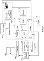
- the field detection circuitry 80 may include a processor 178.
- the processor 178 of some embodiments includes a universal asynchronous receiver/transmitter (UART) 180, a pulse width modulator (PWM) 182, an analog-to-digital converter (ADC) 184, and a general-purpose input/output (GPIO) 186.
- UART universal asynchronous receiver/transmitter
- PWM pulse width modulator
- ADC analog-to-digital converter
- GPIO general-purpose input/output
- the processor 178 may be embodied as various hardware-based processing means such as a microprocessor, a coprocessor, a controller or various other computing or processing devices including integrated circuits such as, for example, an ASIC (application specific integrated circuit), an FPGA (field programmable gate array), some combination thereof, or the like.
- the processor 178 may comprise a plurality of processors. The plurality of processors may be in operative communication with each other and may be collectively configured to perform one or more functionalities of the control apparatus 140 as described herein.
- the UART 180 is in communication with a Bluetooth device 188.
- the PWM 182 sends signals to the speaker 112 to activate the speaker 112.
- the antenna 164 sends signals to a signal amplifier and bandpass filter 190.
- the signal amplifier and bandpass filter 190 sends signals to the ADC 184.
- the signal amplifier and bandpass filter 190 also sends signals to a comparator 192 which sends signals to the GPIO 186.
- the GPIO 186 sends signals to the lights 114 to activate the lights 114.
- the GPIO 186 sends signals to a self-test circuit 194.
- the self-test circuit 194 performs a complete voltage detection system test of the wearable electric field detector 20.
- the self-test circuit 194 sends signals to the antenna 164.
- the GPIO 186 sends signals to the power supply 86.
- the reed switch 82 sends signals to the GPIO 186 and to the power supply 86.
- a complete voltage detection system test is performed by the self-test circuit 194.
- test results are confirmed by emitting a turn-on audio tone from the speaker 112 and/or activating the lights 114. Since the battery door 56 only allow access to the batteries 86 when the wearable electric field detector 20 is closed and turned off, this assures that each time the batteries 86 are replaced a complete voltage detection system test is performed by the self-test circuit 194 before the wearable electric field detector 20 can be used.
- a turn-off audio tone is emitted from the speaker 112.
- the turn-on audio tone is different from the turn-off audio tone.
- the turn-on audio tone plays a series of tones in ascending order
- the turn-off audio tone plays a series of tones in descending order.
- the wearable electric field detector 20 will provide an audible indication of the high voltage by activating the speaker 112 and/or will provide a visual signal by activating the lights 114.
- the field detection circuitry 80 detects a single voltage level when in the open position, or multiple voltage levels in the open position. When this voltage level is detected, the wearable electric field detector 20 activates the speaker 112 and/or the lights 114. The speaker 112 and the lights 114 are directed up towards the head of the wearer to help improve recognition of the indication of the high voltage.
- the wearable electric field detector 20 will provide an audible signal by activating the speaker 112 and/or will provide a visual indication of the high voltage by activating the lights 114.
- the field detection circuitry 80 detects multiple voltage levels when in the open position. When a first voltage level is detected, the wearable electric field detector 20 activates the speaker 112 in a particular pattern and/or at a particular volume, and/or activates the lights 114 in a particular pattern and/or activates certain color or colors of the lights 114 and/or activates the lights 114 at a first rate.
- the wearable electric field detector 20 activates the speaker 112 in a particular pattern which is different from the first voltage level and/or at a particular volume which is different from the first voltage level, and/or activates the lights 114 in a pattern which is different from the first voltage level and/or activates certain color or colors of the lights 114 which are different from the first voltage level and/or activates the lights 114 at a second rate which is different from the first voltage level.
- the wearable electric field detector 20 activates the speaker 112 in a particular pattern which is different from the first and second voltage levels and/or at a particular volume which is different from the first and second voltage levels, and/or activates the lights 114 in a pattern which is different from the first and second voltage levels and/or activates certain color or colors of the lights 114 which are different from the first and second voltage levels and/or activates the lights 114 at a second rate which is different from the first and second voltage levels.
- the speaker 112 and the lights 114 are directed up towards the head of the wearer to help improve recognition of the indication of the high voltage.
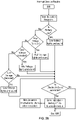
- FIGS. 25 and 26 show a flowchart of an example logic 200 of the firmware of the wearable electric field detector 20.
- the firmware includes an Interrupt Service Routine (ISR).
- ISR is a set of code that is repeated after a small fixed time interval (about 67 milliseconds), so in the main loop the processor 178 is reading voltages and setting registers, but no change in indication (sound or lights) takes place until the next ISR.
- the gaskets 48, 76, 140 deter the ingress of water into the inner housing 22.
- the water-resistant fabric 110 deters the ingress of water into the housing 108 of the speaker 112.
Landscapes
- Physics & Mathematics (AREA)
- General Physics & Mathematics (AREA)
- Electromagnetism (AREA)
- Battery Mounting, Suspending (AREA)
- Arrangement Of Elements, Cooling, Sealing, Or The Like Of Lighting Devices (AREA)
- Emergency Alarm Devices (AREA)
Description
- The invention relates to a wearable electric field detector according to the preamble of claim 1.
- Reliably detecting high voltage on distribution and transmission voltage power lines is critical to the jobs performed by electric utility linemen. These jobs are performed more quickly and safely when the voltage detection is also convenient and easy to use.
- From the anonymous disclosure is known "V-Watch Personal Voltage Detectors", 1 January 2015 (2015-01-01), XP055502916. The wearable electric field detector known from this disclosure gives the user no convenient means to handle the detector in view of the inner and outer housing. Concerning state of the art, further is to refer to
EP 1 296 150 A1 . - Starting from the first mentioned reference, the invention is concerned with the problem to provide a wearable field detector, which is even conveniently built to be used by a user.
- This problem is solved with the features of independent claim 1, preferred additional embodiments are defined in dependent claims 2 to 15.
- This Summary is provided merely for purposes of summarizing some example embodiments so as to provide a basic understanding of some aspects of the disclosure. Other embodiments, aspects, and advantages of various disclosed embodiments will become apparent from the following detailed description taken in conjunction with the accompanying drawings, which illustrate, by way of example, the principles of the described embodiments.
- The organization and manner of the structure and operation of the disclosed embodiments, together with further objects and advantages thereof, may best be understood by reference to the following description, taken in connection with the accompanying drawings, which are not necessarily drawn to scale, wherein like reference numerals identify like elements in which:
-
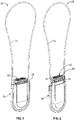
FIG. 1 depicts a front perspective view of a wearable electric field detector in a closed position; -
FIG. 2 depicts a front perspective view of the wearable electric field detector in an open position; -
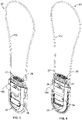
FIG. 3 depicts a rear perspective view of the wearable electric field detector in the closed position; -
FIG. 4 depicts a rear perspective view of the wearable electric field detector in the open position; -
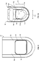
FIG. 5 depicts a rear elevation view of the wearable electric field detector in the closed position; -
FIG. 6 depicts a rear elevation view of the wearable electric field detector in the open position; -
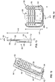
FIG. 7 depicts an exploded, rear perspective view of the wearable electric field detector; -
FIG. 8 depicts a front perspective view of a body of an inner housing of the wearable electric field detector; -
FIG. 9 depicts a rear perspective view of the body of the inner housing; -
FIG. 10 depicts a side elevation view of the body of the inner housing; -
FIG. 11 depicts a rear elevation view of the body of the inner housing with a battery door omitted; -
FIG. 12 depicts a front perspective view of the battery door which is attached to the body of the inner housing; -
FIG. 13 depicts a side elevation view of the battery door; -
FIG. 14 depicts a front elevation view of the battery door; -
FIG. 15 depicts a top perspective view of a cap of the inner housing of the wearable electric field detector; -
FIG. 16 depicts a top plan view of the cap of the inner housing; -
FIG. 17 depicts a bottom plan view of the cap of the inner housing; -
FIG. 18 depicts a perspective view of an acoustic and light chamber mounted within the cap of the inner housing; -
FIG. 19 depicts an elevation view of the acoustic and light chamber; -
FIG. 20 depicts an exploded is an exploded perspective view of the acoustic and light chamber; -
FIG. 21 depicts a front perspective view of an outer housing of the wearable electric field detector; -
FIG. 22 depicts a rear perspective view of the outer housing; -
FIG. 23 depicts a rear elevation view of an embodiment of the outer housing; -
FIG. 24 depicts a circuit block diagram of the wearable electric field detector; and -
FIGS. 25 and26 show a flowchart of example logic of the firmware of the wearable electric field detector. - While the disclosure may be susceptible to embodiment in different forms, there is shown in the drawings, and herein will be described in detail, a specific embodiment with the understanding that the present disclosure is to be considered an exemplification of the principles of the disclosure, and is not intended to limit the disclosure to that as illustrated and described herein. Therefore, unless otherwise noted, features disclosed herein may be combined together to form additional combinations that were not otherwise shown for purposes of brevity. It will be further appreciated that in some embodiments, one or more elements illustrated by way of example in a drawing(s) may be eliminated and/or substituted with alternative elements within the scope of the disclosure.
- The present disclosure relates to the field of voltage detection, and more particularly to a wearable
electric field detector 20. The wearableelectric field detector 20 is designed to provide an early warning to the wearer of the proximity of nearby high voltage conductors. In some embodiments, the high voltage conductors are alternating current (AC) conductors. - Generally, the wearable
electric field detector 20 includes aninner housing 22 which generally includes abody 24 andcap 26 which houseselectrical components 28 therein, and anouter housing 30. In a closed position as shown inFIGS. 1 ,3 and5 , theinner housing 22 is fully seated within theouter housing 30 and only thecap 26 of theinner housing 22 is exposed outwardly of theouter housing 30. In an open position as shown inFIGS. 2 ,4 and6 , thecap 26 and anupper portion 32 of thebody 24 of theinner housing 22 extend from theouter housing 30 and are exposed. - As shown in
FIGS. 8-11 , thebody 24 of theinner housing 22 has front andrearwalls side walls rear walls bottom wall 42 closing the lower ends of the front, rear andside walls ended cavity 44, seeFIG. 7 , is formed within thebody 24. Thecavity 44 defines an opening 46 seeFIG. 7 , in the upper end of thebody 24. In an embodiment, thebody 24 is formed of plastic. In an embodiment, the front andrear walls side walls bottom wall 42 have a front wall portion extending at an angle from thefront wall 34, a rear portion extending at an angle from therear wall 36, and a central section which is perpendicular to the front andrear walls rear walls bottom wall 42 is curved. - In some embodiments, the
body 24 is formed of a first part having thefront wall 34 and a front portion of theside walls bottom wall 42 and a second part having therear wall 36 and a rear portion of theside walls bottom wall 42. The parts are mated together by suitable known means. In an embodiment, agasket 48, seeFIG. 7 , is provided between the parts to provide a seal. In an embodiment, the parts are connected together by mating latch arms. In an embodiment, the parts are connected together by ultrasonic welding. Other means for mating the parts together are within the scope of the present disclosure. - A battery door opening 50, see
FIG. 11 , is provided through therear wall 36. The battery door opening 50 has an outer portion which forms arecess 52 around the perimeter of the battery door opening 50 and extends from theouter surface 36a of therear wall 36 and an inner portion which forms a throughopening 54 and extends from therecess 52 to the inner surface 36b of therear wall 36. - The
body 24 of theinner housing 22 further includes abattery door 56,FIGS. 12-14 , attached to therear wall 36. In an embodiment, thebattery door 56 is formed of awall 58, alatch ear 60 extending from an end of thewall 58, anengagement ear 62 extending from the opposite end of the wall, and aspring arm 64 extending from thewall 58. - The
wall 58 has anupper portion 66 and alower portion 68. As shown inFIGS. 13 and 14 , thewall 58 has a height HI which is defined from an upper end of thewall 58 to a lower end of thewall 58, and a width W1 which is defined from one side of thewall 58 to the other side of thewall 58. As shown inFIG. 13 , theupper portion 66 of thewall 58 has a thickness T1 defined between outer and inner surfaces of theupper portion 66, and thelower portion 68 has a thickness T2 defined between outer and inner surfaces of thelower portion 68. The thickness T1 of theupper portion 66 is less than the thickness T2 of thelower portion 68, such that ashoulder 70 is formed between the upper andlower portions - The
latch ear 60 extends from the inner surface of thewall 58. Theengagement ear 62 extends from thewall 58 at an opposite end of thewall 58 to that which thelatch ear 60 extends. Theengagement ear 62 has a width which is substantially less than the width of thewall 58, such that aspace 72 is formed between an inner surface of theengagement ear 62 and the inner surface of thewall 58. Thespring arm 64 extends from the inner surface of thewall 58 and from the same end of thewall 58 as theengagement ear 62. In an embodiment, thelatch ear 60 extends outwardly from the upper end of thewall 58, and theengagement ear 62 and thespring arm 64 extend from the lower end of thewall 58. In an embodiment, thespring arm 64 has a hook shaped end. In some embodiments, thespring arm 64 is formed of the same material as thewall 58, and in some embodiments is integrally formed therewith. In some embodiments, thespring arm 64 is formed of a different material than the material of thewall 58 and is attached thereto. - The
battery door 56 is removably mounted to therear wall 36 of thebody 24. To attach thebattery door 56, the perimeter of thebattery door 56 seats within therecess 52, the hook of thespring arm 64 and thelatch ear 60 engage with the inner surface 36b of therear wall 36. When thebattery door 56 is mounted to therear wall 36 of thebody 24, theouter surface 66a of theupper portion 66 of thebattery door 56 wall is flush with, or generally flush with, theouter surface 36a of therear wall 36 of thebody 24, and theouter surface 68a of thelower portion 68 of thebattery door 56 extends outwardly from theouter surface 36a of therear wall 36 of thebody 24. When thebattery door 56 is mounted to therear wall 36 of thebody 24, theengagement ear 62 is spaced from theouter surface 36a of therear wall 36 of thebody 24 such that afinger space 74, seeFIG. 10 , is provided. In an embodiment, thebattery door 56 and therecess 52 are rectangular. Agasket 76, seeFIG. 7 , is provided between thebattery door 56 and therear wall 36 of thebody 24 to provide a seal between the parts. In an embodiment, the seal is at least partially water resistant. In an embodiment, the seal is 100% absolute waterproof. - As shown in
FIG. 7 , theelectrical components 28 within thebody 24 includes acircuit board 78, which is some embodiments is a printed circuit board or a printed wiring board. Thecircuit board 78 is mounted within thecavity 44 formed in thebody 24. Thecircuit board 78 includesfield detection circuitry 80 which is configured to detect voltage in the electric field in the environment around the wearer of the wearableelectric field detector 20 and to determine whether the detected voltage meets or exceeds a voltage threshold, and in response to the detection by thefield detection circuitry 80 of an overvoltage, alerts the wearer of the overvoltage condition. An examplefield detection circuitry 80 is manufactured by HD Electric Company, for example, as used in the WATCHMAN® work area voltage detector, part number WM-01. Thecircuit board 78 further includes aswitch 82, such as a reed switch, mounted thereon which is in communication with thefield detection circuitry 80. It will be appreciated, however, that a reed switch is one example of a switch that may be used to implementswitch 82, and where theswitch 82 is referred to herein as a "reed switch", it is by way of example, and not by way of limitation. - A
battery holder 84, which holds the power supply which in some embodiments is one ormore batteries 86, is mounted within theinner housing 22 and in some embodiments, is attached to thecircuit board 78. Thebattery holder 84 is positioned such that it is proximate to thebattery opening 50 in thebody 24. When thebattery door 56 is opened, the one ormore batteries 86 can be removed from thebattery holder 84 and replaced. The one ormore batteries 86 are in the electrical contact with thecircuit board 78 and provide power to thecircuit board 78 as discussed herein. - As shown in
FIGS. 15-17 , thecap 26 has front andrear walls side walls rear walls top wall 96 closing the upper ends of the front, rear andside walls cavity 98 is formed within thecap 26. Thecavity 98 defines anopening 100 in the lower end of thecap 26. Thecap 26 is formed of translucent materials. In an embodiment, thecap 26 is formed of plastic. In an embodiment, outer surfaces of the front andrear walls ribs 102 which enable a wearer to more easily grip thecap 26. - The
top wall 96 has one ormore openings 104 provided therethrough which extend from an upper surface to a lower surface of thetop wall 96. The one ormore openings 104 are in communication with thecavity 98. - An acoustic and
light chamber 106, seeFIGS. 7 and18-20 , is mounted within thecap 26. The acoustic andlight chamber 106 includes ahousing 108 which houses some of theelectrical components 28 and a water-resistant fabric 110 which protects theelectrical components 28. Theelectrical components 28 in the acoustic andlight chamber 106 include, but are not limited to, aspeaker 112 mounted within thehousing 108, and plurality oflights 114 mounted to thehousing 108. - In an embodiment, the
housing 108 has acentral body 116 with anarm 118 extending outwardly from each side of thecentral body 116. Thecentral body 116 has front andrear walls side walls rear walls bottom walls walls cavity 132 is formed therein. Electrical components (not shown) can be provided in thecavity 132. Aspeaker opening 134 is provided through thetop wall 128 of the housing. In an embodiment, thearms 118 extend outwardly from theside walls - One or more layers of water-
resistant fabric 110 is attached to thetop wall 122 of thehousing 108 and cover thespeaker opening 122 to deter the ingress of water into thehousing 108. In an embodiment, the water-resistant fabric 110 is between two layers offoam foam opening speaker opening 134 in thehousing 108. The lower layer offoam 138 is attached by suitable means to thetop wall 128 of thehousing 108. It will be appreciated that one or more layers of an alternative water-resistant material, such as a waterproof film, may be used in addition to or in lieu offabric 110 within the scope of the disclosure. In this regard, any material that is water resistant while providing for at least partial sound permeability may be used in some embodiments providing for protection against water ingress into thehousing 108. - The
lights 114 are attached to thearms 118 such that the illumination source of each light 114 is directed upwardly. Non-limiting examples of an illumination source includes, but is not limited to, light emitting diodes (LEDs), incandescent bulbs, etc. - The acoustic and
light chamber 106 is mounted within thecap 26 such that the illumination sources of thelights 114 are proximate to thetop wall 96 of thecap 26 and thespeaker opening 134 is proximate to the one ormore openings 104 in thetop wall 96 of thecap 26. The water-resistant fabric 110 is visible through the one ormore openings 104 and allows for sound to travel through thecap 26. - The
cap 26 is attached to the upper end of thebody 24 and closes theopening 46 of thebody 24. In an embodiment, agasket 140, seeFIG. 7 , is provided between the upper end of thebody 24 and the lower end of thecap 26. Thespeaker 112 and thelights 114 are electrically connected to thecircuit board 78. - In an embodiment, the
cap 26 is wider than thebody 24 such that anoverhang 142, seeFIG. 10 , is formed by thecap 26. In an embodiment, theoverhang 142 is formed around the entire perimeter of thecap 26. In some embodiments, theoverhang 142 is formed around a portion or portions of the perimeter of thecap 26. - In some embodiments, an
engagement flange 144, seeFIG. 17 , extends downwardly from the lower ends of thewalls cap 26. In some embodiments, theengagement flange 142 extends around the entire perimeter formed by thewalls cap 26. In some embodiments, theengagement flange 144 extends around a portion of the perimeter formed by thewalls cap 26. In an embodiment, theengagement flange 144 is offset inwardly from the outer surfaces of thewalls cap 26 and theengagement flange 144 is sized to fit within theopening 46 of thebody 24. - As shown in
FIG. 21-23 , theouter housing 30 has front andrear walls side walls rear walls bottom wall 154 closing the lower ends of the front, rear andside walls cavity 156 is formed within theouter housing 30. Thecavity 156 defines anopening 158 in the upper end of theouter housing 30. In an embodiment, theouter housing 30 is formed of plastic. In an embodiment, the front andrear walls side walls bottom wall 154 have a front wall portion extending at an angle from thefront wall 144, a rear portion extending at an angle from therear wall 146, and a central section which is perpendicular to the front andrear walls rear walls bottom wall 154 is curved. - In some embodiments, the
outer housing 30 is formed of a first part having thefront wall 146 and a front portion of theside walls bottom wall 154 and a second part having therear wall 148 and a rear portion of theside walls bottom wall 154. The parts are mated together by suitable known means. In an embodiment, the parts are connected together by mating latch arms. In an embodiment, the parts are connected together by ultrasonic welding. Other means for mating the parts together are within the scope of the present disclosure. - A battery door opening 160 is provided through the
rear wall 146. As shown inFIG. 23 , the battery door opening 160 has a height H2 which is defined from an upper end of the battery door opening 160 to a lower end of the battery door opening 160, and a width W2 which is defined from one side of the battery door opening 160 to the other side of thebattery door opening 160. Thebattery door 56 is sized such that it has a height HI which is less than the height H2 of the battery door opening 160 and a width W1 which is less than the width W2 of thebattery door opening 160. - A
magnet 162, seeFIGS. 22 and23 is mounted on the inner surface of thefront wall 146 of theouter housing 30 with in thecavity 156. - In some embodiments, the
outer housing 30 is formed of a first part having the front wall and a front portion of the side walls and the bottom wall and a second part having the rear wall and a rear portion of the side walls and the bottom wall. The parts are mated together by suitable known means. In some embodiments, a gasket (not shown) is provided between the parts. - When assembled and in a closed position as shown in
FIGS. 1 ,3 and5 , thebody 24 of theinner housing 22 seats within thecavity 156 ofouter housing 30. When in the closed position, only thetranslucent cap 26 of theinner housing 22 is visible external to the outer housing 30 (if theengagement flange 144 is provided, theengagement flange 144 is not visible as it is inside thebody 24 of the inner housing 22) at the top of the wearableelectric field detector 20. Thewalls body 24 and theupper portion 66 of thebattery door 56 may abut against thewalls outer housing 30. Thelower portion 68 of thebattery door 56 extends through the battery door opening 160 in therear wall 146 of theouter housing 30. In an embodiment, when assembled and in the closed position, a lower end 58a of thewall 58 of thebattery door 56 is proximate to alower edge 160a of thebattery door opening 160. In this closed position, thebattery door 56 is completely visible through thebattery door opening 160. This allows a wearer to remove thebattery door 56 by grasping theengagement ear 62 and pulling thebattery door 56 outwardly from theinner housing 22 through the battery door opening 160 in theouter housing 30. When thebattery door 56 is pulled by itsengagement ear 62, thespring arm 64 flexes to release its engagement with therear wall 146 and thelatch ear 60 is slide out from under therear wall 146 to allow thebattery door 56 to be released. - In an embodiment, the
inner housing 22 is slidable relative to theouter housing 30. - To open the wearable
electric field detector 20 to place the wearableelectric field detector 20 in an open position as shown inFIGS. 2 ,4 and6 , thecap 26 is grasped by a wearer and pulled outwardly from theouter housing 30. As thecap 26 is pulled outwardly from theouter housing 30, theinner housing 22 slides relative to theouter housing 30 and exposes theupper portion 32 of thebody 24 of theinner housing 22. Thebody 24 is formed of a different color than theouter housing 30. As an example, thebody 24 is red, while theouter housing 30 is green. When theupper portion 32 of thebody 24 of theinner housing 22 is exposed in the open position, the wearer is given a visual indication that the wearableelectric field detector 20 has been opened since the differently coloredupper portion 32 of thebody 24 is now visible. During this movement, thelower portion 68 of thebattery door 56 slides along the battery door opening 160 in therear wall 146 of theouter housing 30. In an embodiment, thebattery door 56 slides along the battery door opening 160 until theshoulder 70 of thebattery door 56 contacts anupper edge 160b of thebattery door opening 160. Theupper portion 66 of thebattery door 56 is proximate to the inner surface of therear wall 146 of theouter housing 30 such that theupper portion 66 is not visible. Therefore, thebattery door 56 cannot be removed in this open position since theupper portion 66 of thebattery door 56 is behind therear wall 146 of theouter housing 30. - When the
inner housing 22 is pulled outwardly from theouter housing 30 to the open position, thereed switch 82 on theinner housing 22 comes into proximity with themagnet 162 on theouter housing 30. This closes theswitch 82 which enables the electrical connection between thebatteries 86 and thefield detection circuitry 80 such that the wearableelectric field detector 20 is turned on and activated. - As previously noted, the use of a reed switch to implement the
switch 82 is described solely by way of example, and not by way of limitation. In this regard, any type of switch, sensor, or combination thereof that may be triggered to selectively provide an electrical connection between thebatteries 86 and thefield detection circuitry 80 in response to theinner housing 22 being pulled outwardly from theouter housing 30 to the open position may be substituted for theswitch 82 within the scope of the disclosure. - To close the wearable
electric field detector 20 into the closed position as shown inFIG. 1 ,3 and5 , thecap 26 is pushed inwardly into theouter housing 30 until theoverhang 142 engages the upper end of theouter housing 30. As thecap 26 is pushed inwardly into theouter housing 30, theinner housing 22 slides relative to theouter housing 30 and theupper portion 32 of thebody 24 of theinner housing 22 is hidden from view. During this movement, thelower portion 68 of thebattery door 56 slides along the battery door opening 160 in therear wall 146 of theouter housing 30. In an embodiment, thebattery door 56 slides along the battery door opening 160 until the lower end 58a of thewall 58 of thebattery door 56 contacts thelower edge 160a of the battery door opening 160 and theentire battery door 56 is visible through thebattery door opening 160. - When the
inner housing 22 is pushed inwardly into theouter housing 30 to the closed position, theswitch 82 on theinner housing 22 is moved out of proximity of themagnet 162 on theouter housing 30. This opens theswitch 82 thereby preventing an electrical connection between thebatteries 86 and thefield detection circuitry 80 such that the wearableelectric field detector 20 is turned off and deactivated. As such, thebatteries 86 supply power to thefield detection circuitry 80 only when the wearableelectric field detector 20 is open. - In some embodiments, an
antenna 164 is provided within theinner housing 22 and is in communication with thecircuit board 78. In some embodiments, theantenna 164 is attached to thecircuit board 78. - In some embodiments, a
spring clip 166, seeFIG. 23 , is attached to therear wall 148 of theouter housing 30 by suitable means, such as arivet 168. In some embodiments, therear wall 148 of theouter housing 30 hasrivet receiving opening 170 therethrough through which therivet 168 extends. In an embodiment, thespring clip 166 is positioned above thebattery door opening 160. A wearer can use thespring clip 166 to attach the wearableelectric field detector 20 to the wearer's clothing. - In some embodiments, the wearable
electric field detector 20 includes alanyard 172 attached to theouter housing 30 by alanyard housing 174. Thelanyard housing 174 is attached to theouter housing 30 by suitable means, such as latches or ultrasonic welding. In some embodiments, thelanyard 172 is made of a fireproof material and may be formed of KEVLAR® material. In some embodiments, thelanyard housing 174 mirrors the shape of theouter housing 30. In an embodiment, thelanyard housing 174 is U-shaped. Thelanyard housing 174 provides apassageway 176 through which thelanyard 172 extends. The wearer can wear the wearableelectric field detector 20 around his/her neck by using thelanyard 172 such that thebody 24 can be positioned at the chest of the wearer. In some embodiments, thelanyard 172 includes an adjustable spring clamp (not shown) to adjust the length of thelanyard 172; this spring clamp also releases thelanyard 172 when sufficient force is applied should thelanyard 172 become caught on an object. - As shown in
FIG. 24 , thefield detection circuitry 80 may include aprocessor 178. Theprocessor 178 of some embodiments includes a universal asynchronous receiver/transmitter (UART) 180, a pulse width modulator (PWM) 182, an analog-to-digital converter (ADC) 184, and a general-purpose input/output (GPIO) 186. However, it will be appreciated that the configuration ofprocessor 178 illustrated inFIG. 24 is provided by way of example and not by way of limitation, as theprocessor 178 may be embodied in a variety of forms. For example, theprocessor 178 may be embodied as various hardware-based processing means such as a microprocessor, a coprocessor, a controller or various other computing or processing devices including integrated circuits such as, for example, an ASIC (application specific integrated circuit), an FPGA (field programmable gate array), some combination thereof, or the like. Although illustrated as a single processor, it will be appreciated that theprocessor 178 may comprise a plurality of processors. The plurality of processors may be in operative communication with each other and may be collectively configured to perform one or more functionalities of thecontrol apparatus 140 as described herein. In some embodiments, theUART 180 is in communication with aBluetooth device 188. ThePWM 182 sends signals to thespeaker 112 to activate thespeaker 112. In some embodiments, theantenna 164 sends signals to a signal amplifier andbandpass filter 190. The signal amplifier andbandpass filter 190 sends signals to theADC 184. The signal amplifier andbandpass filter 190 also sends signals to acomparator 192 which sends signals to theGPIO 186. TheGPIO 186 sends signals to thelights 114 to activate thelights 114. TheGPIO 186 sends signals to a self-test circuit 194. The self-test circuit 194 performs a complete voltage detection system test of the wearableelectric field detector 20. The self-test circuit 194 sends signals to theantenna 164. TheGPIO 186 sends signals to thepower supply 86. Thereed switch 82 sends signals to theGPIO 186 and to thepower supply 86. - In some embodiments, when the wearable
electric field detector 20 is opened such that the wearableelectric field detector 20 is activated, a complete voltage detection system test is performed by the self-test circuit 194. In some such embodiments, test results are confirmed by emitting a turn-on audio tone from thespeaker 112 and/or activating thelights 114. Since thebattery door 56 only allow access to thebatteries 86 when the wearableelectric field detector 20 is closed and turned off, this assures that each time thebatteries 86 are replaced a complete voltage detection system test is performed by the self-test circuit 194 before the wearableelectric field detector 20 can be used. In some embodiments, when the wearableelectric field detector 20 is closed such that the wearableelectric field detector 20 is deactivated, a turn-off audio tone is emitted from thespeaker 112. In some embodiments, the turn-on audio tone is different from the turn-off audio tone. As an example, the turn-on audio tone plays a series of tones in ascending order, and the turn-off audio tone plays a series of tones in descending order. - If the wearer comes into proximity of a high voltage conductor when the wearable
electric field detector 20 is in the open position, the wearableelectric field detector 20 will provide an audible indication of the high voltage by activating thespeaker 112 and/or will provide a visual signal by activating thelights 114. In some embodiments, thefield detection circuitry 80 detects a single voltage level when in the open position, or multiple voltage levels in the open position. When this voltage level is detected, the wearableelectric field detector 20 activates thespeaker 112 and/or thelights 114. Thespeaker 112 and thelights 114 are directed up towards the head of the wearer to help improve recognition of the indication of the high voltage. - If the wearer comes into proximity of a high voltage conductor when the wearable
electric field detector 20 is in the open position, the wearableelectric field detector 20 will provide an audible signal by activating thespeaker 112 and/or will provide a visual indication of the high voltage by activating thelights 114. In some embodiments, thefield detection circuitry 80 detects multiple voltage levels when in the open position. When a first voltage level is detected, the wearableelectric field detector 20 activates thespeaker 112 in a particular pattern and/or at a particular volume, and/or activates thelights 114 in a particular pattern and/or activates certain color or colors of thelights 114 and/or activates thelights 114 at a first rate. When a second voltage level is detected, the wearableelectric field detector 20 activates thespeaker 112 in a particular pattern which is different from the first voltage level and/or at a particular volume which is different from the first voltage level, and/or activates thelights 114 in a pattern which is different from the first voltage level and/or activates certain color or colors of thelights 114 which are different from the first voltage level and/or activates thelights 114 at a second rate which is different from the first voltage level. When a third voltage level is detected, the wearableelectric field detector 20 activates thespeaker 112 in a particular pattern which is different from the first and second voltage levels and/or at a particular volume which is different from the first and second voltage levels, and/or activates thelights 114 in a pattern which is different from the first and second voltage levels and/or activates certain color or colors of thelights 114 which are different from the first and second voltage levels and/or activates thelights 114 at a second rate which is different from the first and second voltage levels. Thespeaker 112 and thelights 114 are directed up towards the head of the wearer to help improve recognition of the indication of the high voltage. -
FIGS. 25 and26 show a flowchart of anexample logic 200 of the firmware of the wearableelectric field detector 20. The firmware includes an Interrupt Service Routine (ISR). The ISR is a set of code that is repeated after a small fixed time interval (about 67 milliseconds), so in the main loop theprocessor 178 is reading voltages and setting registers, but no change in indication (sound or lights) takes place until the next ISR. - The
gaskets inner housing 22. The water-resistant fabric 110 deters the ingress of water into thehousing 108 of thespeaker 112. - While particular embodiments are illustrated in and described with respect to the drawings, it is envisioned that those skilled in the art may devise various modifications without departing from the scope of the appended claims. It will therefore be appreciated that the scope of the disclosure and the appended claims is not limited to the specific embodiments illustrated in and discussed with respect to the drawings and that modifications and other embodiments are intended to be included within the scope of the disclosure and appended claims. Moreover, although the foregoing descriptions and the associated drawings describe example embodiments in the context of certain example combinations of elements and/or functions, it should be appreciated that different combinations of elements and/or functions may be provided by alternative embodiments without departing from the scope of the disclosure and the appended claims.
Claims (15)
- A wearable electric field detector configured to be worn by a wearer in an environment, comprising an outer housing (30); an inner housing (22) within the outer housing, the inner housing having a body (24) defining a cavity (44) therein, a field detection circuitry (80) provided within the cavity of the inner housing and configured to detect voltage in an electric field in the environment around the wearer, batteries (86) mounted within the cavity, at least one of a speaker (112) and a light source (114) mounted in the inner housing and in communication with the field detection circuitry and configured to be activated by the field detection circuitry, the wearable electric field detector being characterized by:the inner housing comprising a cap (26) extending from the body and always extending from the outer housing, the cavity being closed by the cap, the inner housing being slidable relative to the outer housing when a user grasps the cap and slides outwardly the inner housing relative to the outer housing from a closed position to an open position,wherein the body is concealed within the outer housing and the cap is visible when the inner housing is in the closed position, and the body is only partially visible and the cap is visible when the inner housing is in the open position; anda switch (82), sensor, or combination thereof configured to be triggered to provide an electrical connection between the batteries and the field detection circuitry when the inner housing is moved to the open position.
- The wearable electric field detector of claim 1, being characterized in that the outer housing is a first color and the body is a second, different color.
- The wearable electric field detector of claim 1, further being characterized by the cap having an overhang (142) which extends outwardly from the outer housing and which prevents the further entry of the cap into the outer housing when the inner housing is moved to the closed position.
- The wearable electric field detector of claim 1, being characterized in that the at least one of a speaker and a light source mounted in the inner housing are proximate to an upper end of the inner housing.
- The wearable electric field detector of claim 1, further being characterized by the body having a battery door (56) attached thereto, the battery door being detachable from the body, wherein further, preferably, the outer housing has a battery door opening (160) provided therethrough, the battery door opening being larger than the battery door such that the battery door can pass therethrough.
- The wearable electric field detector according to claim 5, characterized in that the battery door has an upper portion and a lower portion, the lower portion extending outwardly from the upper portion, the lower portion extending into battery door opening when the inner housing is in the closed or in the open position, and wherein the upper portion of the battery door is visible through the battery door opening when the inner housing is in the closed position, and at least a portion of the upper portion of the battery door is not visible through the battery door opening when the inner housing is in the open position.
- The wearable electric field detector of claim 1, further being characterized by the body having a battery door (56) attached thereto, the battery door being detachable from the body only when the inner housing is in the closed position; and
wherein the field detection circuitry includes a self-test circuit (194) which is activated only when the inner housing is moved to the open position and/or, preferably, wherein the field detection circuitry is configured to indicate results from the self-test circuit by emitting a turn-on audio tone from the speaker and/or activating the lights, wherein further, preferably, the field detection circuitry is configured to activate the speaker to emit a turn-off audio tone when the inner housing is moved to the closed position. - The wearable electric field detector of claim 1, further being characterized by the cap having at least one opening (122) therethrough, and including a water-resistant fabric (110) covering the at least one opening.
- The wearable electric field detector of claim 1, further being characterized by comprising the switch and a magnet (162) on the outer housing, wherein the switch and the magnet are not in proximity to each other when the inner housing in the closed position, and wherein the switch and the magnet are in proximity to each other when the inner housing in the open position such that the switch is activated which in turn, activates the field detection circuitry.
- The wearable electric field detector of claim 1, further being characterized by the field detection circuitry including a self-test circuit (194) which is activated only when the inner housing is moved to the open position, wherein, preferably, the field detection circuitry is configured to indicate results from the self-test circuit by emitting a turn-on audio tone from the speaker and/or activating the lights.
- The wearable electric field detector of claim 10, characterized in that the field detection circuitry is configured to activate the speaker to emit a turn-off audio tone when the inner housing is moved to the closed position.
- The wearable electric field detector of claim 1, further being characterized in that the field detection circuitry is configured to cause the speaker to emit a turn-on audio tone from the speaker when the inner housing is moved to the open position and the field detection circuitry is configured to cause the speaker to emit a turn-off audio tone from the speaker when the inner housing is moved to the closed position, the turn-on audio tone being different from the turn-off audio tone.
- The wearable electric field detector of claim 1, further being characterized by a lanyard attached to the outer housing, wherein, preferably, the lanyard is fireproof.
- The wearable electric field detector of claim 1, further being characterized in that the field detection circuitry is configured to detect multiple voltage levels when in the inner housing is in the open position,wherein when a first voltage level is detected, the field detection circuitry activates the speaker in a particular pattern and/or at a particular volume, and/or activates the lights in a particular pattern and/or activates certain color or colors of the lights and/or activates the lights at a first rate, andwherein when a second voltage level is detected, the field detection circuitry activates the speaker in a particular pattern which is different from the first voltage level and/or at a particular volume which is different from the first voltage level, and/or activates the lights in a pattern which is different from the first voltage level and/or activates certain color or colors of the lights which are different from the first voltage level and/or activates the lights at a second rate which is different from the first voltage level.
- The wearable electric field detector of claim 14, further being characterized by, when a third voltage level is detected, the field detection circuitry activates the speaker in a particular pattern which is different from the first and second voltage levels and/or at a particular volume which is different from the first and second voltage levels, and/or activates the lights in a pattern which is different from the first and second voltage levels and/or activates certain color or colors of the lights which are different from the first and second voltage levels and/or activates the lights at a second rate which is different from the first and second voltage levels.
Applications Claiming Priority (1)
| Application Number | Priority Date | Filing Date | Title |
|---|---|---|---|
| US201762486672P | 2017-04-18 | 2017-04-18 |
Publications (2)
| Publication Number | Publication Date |
|---|---|
| EP3392665A1 EP3392665A1 (en) | 2018-10-24 |
| EP3392665B1 true EP3392665B1 (en) | 2022-08-10 |
Family
ID=62025668
Family Applications (1)
| Application Number | Title | Priority Date | Filing Date |
|---|---|---|---|
| EP18167882.2A Active EP3392665B1 (en) | 2017-04-18 | 2018-04-18 | Wearable electric field detector |
Country Status (2)
| Country | Link |
|---|---|
| US (1) | US10802065B2 (en) |
| EP (1) | EP3392665B1 (en) |
Cited By (1)
| Publication number | Priority date | Publication date | Assignee | Title |
|---|---|---|---|---|
| DE102022105066A1 (en) | 2022-03-03 | 2023-09-07 | Dehn Se | Portable voltage detector and voltage hazard warning system |
Families Citing this family (8)
| Publication number | Priority date | Publication date | Assignee | Title |
|---|---|---|---|---|
| CN111402544B (en) * | 2020-03-23 | 2021-08-31 | 朔黄铁路发展有限责任公司 | Safety warning device |
| CN116449676A (en) * | 2022-01-14 | 2023-07-18 | 苹果公司 | Electronic equipment |
| USD1019425S1 (en) * | 2022-04-18 | 2024-03-26 | Illumagear, Inc. | Receiver for a detector cartridge |
| USD1016630S1 (en) * | 2022-04-18 | 2024-03-05 | Illumagear, Inc. | Detector cartridge |
| USD1016631S1 (en) * | 2022-04-18 | 2024-03-05 | Illumagear, Inc. | Receiver for a detector cartridge |
| US12405296B2 (en) | 2022-05-13 | 2025-09-02 | Emerson Professional Tools, Inc. | Electric field detector wearable in multiple orientations |
| US12571825B2 (en) | 2023-07-25 | 2026-03-10 | Emerson Professional Tools, Llc | Wearable electric field detector |
| USD1100692S1 (en) | 2023-10-11 | 2025-11-04 | Emerson Professional Tools, Llc | Wearable electric field detector |
Family Cites Families (30)
| Publication number | Priority date | Publication date | Assignee | Title |
|---|---|---|---|---|
| US4714915A (en) | 1986-09-29 | 1987-12-22 | Marcel Hascal | Portable electrostatic field safety monitor |
| US5001455A (en) | 1989-03-23 | 1991-03-19 | Maniolos/Starchevic | Portable signaling device |
| US5814968A (en) | 1995-06-26 | 1998-09-29 | Long Range Systems, Inc. | Battery charger and rechargeable electronic paging device assembly |
| US6384591B1 (en) | 1997-09-11 | 2002-05-07 | Comsonics, Inc. | Hands-free signal level meter |
| US6170607B1 (en) | 1998-07-01 | 2001-01-09 | Altec Industries, Inc. | Electrical hazard warning system for aerial devices |
| US6677743B1 (en) | 1999-03-05 | 2004-01-13 | Foster-Miller, Inc. | High voltage powerline sensor with a plurality of voltage sensing devices |
| US20050264427A1 (en) | 2000-03-03 | 2005-12-01 | The Gov. Of The Usa As Repres. By The Secretary Of The Dept. Of Health And Human Services | Electrical injury protection system |
| US6329924B1 (en) * | 2000-03-17 | 2001-12-11 | Hd Electric Company | Wearable electric field detector |
| EP1296150A1 (en) | 2001-09-25 | 2003-03-26 | HD Electric Company | Wearable electric field detector |
| US20050040809A1 (en) | 2003-08-22 | 2005-02-24 | Uber Arthur E. | Power line property measurement devices and power line fault location methods, devices and systems |
| US6998832B1 (en) | 2004-02-26 | 2006-02-14 | Hd Electric Company | High-voltage indicating apparatus and method |
| US20070018841A1 (en) | 2004-11-22 | 2007-01-25 | Nickerson Irvin H | High voltage proximity warning system utilizing wireless sensors and method |
| US20060186872A1 (en) | 2005-02-22 | 2006-08-24 | Mark Trethewey | Electric field detector |
| US20070236358A1 (en) | 2006-04-05 | 2007-10-11 | Street Thomas T | Smoke detector systems, smoke detector alarm activation systems, and methods |
| USD577300S1 (en) | 2006-12-13 | 2008-09-23 | Kister Holding Ag | Piezoelectric sensor |
| US20100052929A1 (en) | 2008-08-21 | 2010-03-04 | Dave Jackett | High voltage proximity warning alarm system |
| US9265331B1 (en) | 2010-01-21 | 2016-02-23 | Hd Electric Company | Wearable carrying case |
| USD622956S1 (en) | 2010-01-29 | 2010-09-07 | Hd Electric Company | Wearable carrying case |
| USD650116S1 (en) | 2010-05-14 | 2011-12-06 | Steelcase Inc. | Lighting device |
| US9215394B2 (en) | 2011-10-28 | 2015-12-15 | Universal Electronics Inc. | System and method for optimized appliance control |
| US9501930B2 (en) | 2011-12-28 | 2016-11-22 | United Safety, Inc. | Power line proximity sensing and warning system |
| US10067170B2 (en) | 2011-12-28 | 2018-09-04 | United Safety, Inc. | Power line proximity sensing and warning system |
| US8786447B1 (en) | 2012-02-26 | 2014-07-22 | Bryan C. Wise | High voltage detection assembly |
| FI124896B (en) | 2012-09-04 | 2015-03-13 | Eltel Networks Oy | Remote voltage detector in a power grid and voltage detection method |
| US9116178B1 (en) | 2012-10-11 | 2015-08-25 | Reliance Controls Corporation | Circuit tester with variable volume audible voltage indication |
| US9494623B2 (en) | 2013-10-01 | 2016-11-15 | Hd Electric Company | High-voltage detector monitoring system |
| CN106795996B (en) | 2014-07-22 | 2019-05-31 | 霍尼韦尔国际公司 | Personal wearable system that detects dangerous voltages and indicates the direction of the source |
| US9970975B2 (en) | 2014-08-14 | 2018-05-15 | Connecticut Analytical Corp. | System for the standoff detection of power line hazards |
| EP3124983B1 (en) | 2015-07-29 | 2019-12-11 | Fameca Electronics | Individual security system comprising a voltage sensor and a lighting system and individual security assembly comprising such a system |
| TWI615062B (en) | 2017-05-16 | 2018-02-11 | 廣達電腦股份有限公司 | Fault detection devices and fault detection methods |
-
2018
- 2018-04-17 US US15/954,899 patent/US10802065B2/en active Active
- 2018-04-18 EP EP18167882.2A patent/EP3392665B1/en active Active
Cited By (1)
| Publication number | Priority date | Publication date | Assignee | Title |
|---|---|---|---|---|
| DE102022105066A1 (en) | 2022-03-03 | 2023-09-07 | Dehn Se | Portable voltage detector and voltage hazard warning system |
Also Published As
| Publication number | Publication date |
|---|---|
| US20180299496A1 (en) | 2018-10-18 |
| EP3392665A1 (en) | 2018-10-24 |
| US10802065B2 (en) | 2020-10-13 |
Similar Documents
| Publication | Publication Date | Title |
|---|---|---|
| US10802065B2 (en) | Wearable electric field detector | |
| US6016099A (en) | Automatically active personal alert safety system | |
| US6457843B1 (en) | Outlet covering system | |
| JP6680821B2 (en) | Door device | |
| SA08290550B1 (en) | Light Sensing Pull Station | |
| AU2012203158A1 (en) | Apparatus and method for shielding an IR detecting diode | |
| CN204994456U (en) | Fishing alarm component of theftproof pole | |
| US20130058073A1 (en) | Illuminated Door Assembly for an Electrical Outlet Cover | |
| EP3498094A1 (en) | Remote controller for a fishing appliance | |
| US12571825B2 (en) | Wearable electric field detector | |
| CN203969466U (en) | A kind of function slide fastener protective device | |
| US20170008604A1 (en) | Underwater Alert Device with Shark Deterrent | |
| US9153113B1 (en) | Oven door smoke sensor | |
| CN206805755U (en) | The one-meter-line device of intelligentized control method | |
| KR102198750B1 (en) | Ear free mask necklace | |
| CN207535860U (en) | A kind of automobile safety seat belt device | |
| CN210431955U (en) | A panel switch with LED indicator light | |
| CN210982593U (en) | Portable individual soldier's safety non-contact electric leakage detection instrument | |
| EP3498093B1 (en) | A fishing appliance and a fishing accessory | |
| KR200487956Y1 (en) | Extension connector with Moisture sensor of Location distinguish to Lifesaving | |
| CN113069111B (en) | Oximeter housing and oximeter | |
| EP3245890B1 (en) | Light-emitting safe buckle | |
| CN219589839U (en) | Temperature measuring device and clothes for measuring body temperature | |
| CN223403437U (en) | Integrated shared hair dryer device | |
| CN215423976U (en) | Fingerprint identification safety cup |
Legal Events
| Date | Code | Title | Description |
|---|---|---|---|
| PUAI | Public reference made under article 153(3) epc to a published international application that has entered the european phase |
Free format text: ORIGINAL CODE: 0009012 |
|
| STAA | Information on the status of an ep patent application or granted ep patent |
Free format text: STATUS: THE APPLICATION HAS BEEN PUBLISHED |
|
| AK | Designated contracting states |
Kind code of ref document: A1 Designated state(s): AL AT BE BG CH CY CZ DE DK EE ES FI FR GB GR HR HU IE IS IT LI LT LU LV MC MK MT NL NO PL PT RO RS SE SI SK SM TR |
|
| AX | Request for extension of the european patent |
Extension state: BA ME |
|
| STAA | Information on the status of an ep patent application or granted ep patent |
Free format text: STATUS: REQUEST FOR EXAMINATION WAS MADE |
|
| 17P | Request for examination filed |
Effective date: 20190424 |
|
| RBV | Designated contracting states (corrected) |
Designated state(s): AL AT BE BG CH CY CZ DE DK EE ES FI FR GB GR HR HU IE IS IT LI LT LU LV MC MK MT NL NO PL PT RO RS SE SI SK SM TR |
|
| RAP1 | Party data changed (applicant data changed or rights of an application transferred) |
Owner name: GREENLEE TOOLS, INC. |
|
| GRAP | Despatch of communication of intention to grant a patent |
Free format text: ORIGINAL CODE: EPIDOSNIGR1 |
|
| STAA | Information on the status of an ep patent application or granted ep patent |
Free format text: STATUS: GRANT OF PATENT IS INTENDED |
|
| RIC1 | Information provided on ipc code assigned before grant |
Ipc: G08B 21/02 20060101ALN20220217BHEP Ipc: G01R 1/04 20060101ALN20220217BHEP Ipc: G08B 7/06 20060101ALI20220217BHEP Ipc: G01R 29/08 20060101ALI20220217BHEP Ipc: H05K 5/02 20060101ALI20220217BHEP Ipc: H05K 5/00 20060101ALI20220217BHEP Ipc: G01R 29/12 20060101AFI20220217BHEP |
|
| INTG | Intention to grant announced |
Effective date: 20220316 |
|
| GRAS | Grant fee paid |
Free format text: ORIGINAL CODE: EPIDOSNIGR3 |
|
| GRAA | (expected) grant |
Free format text: ORIGINAL CODE: 0009210 |
|
| STAA | Information on the status of an ep patent application or granted ep patent |
Free format text: STATUS: THE PATENT HAS BEEN GRANTED |
|
| AK | Designated contracting states |
Kind code of ref document: B1 Designated state(s): AL AT BE BG CH CY CZ DE DK EE ES FI FR GB GR HR HU IE IS IT LI LT LU LV MC MK MT NL NO PL PT RO RS SE SI SK SM TR |
|
| REG | Reference to a national code |
Ref country code: AT Ref legal event code: REF Ref document number: 1510940 Country of ref document: AT Kind code of ref document: T Effective date: 20220815 Ref country code: CH Ref legal event code: EP |
|
| REG | Reference to a national code |
Ref country code: IE Ref legal event code: FG4D |
|
| REG | Reference to a national code |
Ref country code: DE Ref legal event code: R096 Ref document number: 602018038974 Country of ref document: DE |
|
| REG | Reference to a national code |
Ref country code: NL Ref legal event code: MP Effective date: 20220810 |
|
| REG | Reference to a national code |
Ref country code: LT Ref legal event code: MG9D |
|
| PG25 | Lapsed in a contracting state [announced via postgrant information from national office to epo] |
Ref country code: SE Free format text: LAPSE BECAUSE OF FAILURE TO SUBMIT A TRANSLATION OF THE DESCRIPTION OR TO PAY THE FEE WITHIN THE PRESCRIBED TIME-LIMIT Effective date: 20220810 Ref country code: RS Free format text: LAPSE BECAUSE OF FAILURE TO SUBMIT A TRANSLATION OF THE DESCRIPTION OR TO PAY THE FEE WITHIN THE PRESCRIBED TIME-LIMIT Effective date: 20220810 Ref country code: PT Free format text: LAPSE BECAUSE OF FAILURE TO SUBMIT A TRANSLATION OF THE DESCRIPTION OR TO PAY THE FEE WITHIN THE PRESCRIBED TIME-LIMIT Effective date: 20221212 Ref country code: NO Free format text: LAPSE BECAUSE OF FAILURE TO SUBMIT A TRANSLATION OF THE DESCRIPTION OR TO PAY THE FEE WITHIN THE PRESCRIBED TIME-LIMIT Effective date: 20221110 Ref country code: NL Free format text: LAPSE BECAUSE OF FAILURE TO SUBMIT A TRANSLATION OF THE DESCRIPTION OR TO PAY THE FEE WITHIN THE PRESCRIBED TIME-LIMIT Effective date: 20220810 Ref country code: LV Free format text: LAPSE BECAUSE OF FAILURE TO SUBMIT A TRANSLATION OF THE DESCRIPTION OR TO PAY THE FEE WITHIN THE PRESCRIBED TIME-LIMIT Effective date: 20220810 Ref country code: LT Free format text: LAPSE BECAUSE OF FAILURE TO SUBMIT A TRANSLATION OF THE DESCRIPTION OR TO PAY THE FEE WITHIN THE PRESCRIBED TIME-LIMIT Effective date: 20220810 Ref country code: FI Free format text: LAPSE BECAUSE OF FAILURE TO SUBMIT A TRANSLATION OF THE DESCRIPTION OR TO PAY THE FEE WITHIN THE PRESCRIBED TIME-LIMIT Effective date: 20220810 |
|
| REG | Reference to a national code |
Ref country code: AT Ref legal event code: MK05 Ref document number: 1510940 Country of ref document: AT Kind code of ref document: T Effective date: 20220810 |
|
| PG25 | Lapsed in a contracting state [announced via postgrant information from national office to epo] |
Ref country code: PL Free format text: LAPSE BECAUSE OF FAILURE TO SUBMIT A TRANSLATION OF THE DESCRIPTION OR TO PAY THE FEE WITHIN THE PRESCRIBED TIME-LIMIT Effective date: 20220810 Ref country code: IS Free format text: LAPSE BECAUSE OF FAILURE TO SUBMIT A TRANSLATION OF THE DESCRIPTION OR TO PAY THE FEE WITHIN THE PRESCRIBED TIME-LIMIT Effective date: 20221210 Ref country code: HR Free format text: LAPSE BECAUSE OF FAILURE TO SUBMIT A TRANSLATION OF THE DESCRIPTION OR TO PAY THE FEE WITHIN THE PRESCRIBED TIME-LIMIT Effective date: 20220810 Ref country code: GR Free format text: LAPSE BECAUSE OF FAILURE TO SUBMIT A TRANSLATION OF THE DESCRIPTION OR TO PAY THE FEE WITHIN THE PRESCRIBED TIME-LIMIT Effective date: 20221111 |
|
| PG25 | Lapsed in a contracting state [announced via postgrant information from national office to epo] |
Ref country code: SM Free format text: LAPSE BECAUSE OF FAILURE TO SUBMIT A TRANSLATION OF THE DESCRIPTION OR TO PAY THE FEE WITHIN THE PRESCRIBED TIME-LIMIT Effective date: 20220810 Ref country code: RO Free format text: LAPSE BECAUSE OF FAILURE TO SUBMIT A TRANSLATION OF THE DESCRIPTION OR TO PAY THE FEE WITHIN THE PRESCRIBED TIME-LIMIT Effective date: 20220810 Ref country code: ES Free format text: LAPSE BECAUSE OF FAILURE TO SUBMIT A TRANSLATION OF THE DESCRIPTION OR TO PAY THE FEE WITHIN THE PRESCRIBED TIME-LIMIT Effective date: 20220810 Ref country code: DK Free format text: LAPSE BECAUSE OF FAILURE TO SUBMIT A TRANSLATION OF THE DESCRIPTION OR TO PAY THE FEE WITHIN THE PRESCRIBED TIME-LIMIT Effective date: 20220810 Ref country code: CZ Free format text: LAPSE BECAUSE OF FAILURE TO SUBMIT A TRANSLATION OF THE DESCRIPTION OR TO PAY THE FEE WITHIN THE PRESCRIBED TIME-LIMIT Effective date: 20220810 Ref country code: AT Free format text: LAPSE BECAUSE OF FAILURE TO SUBMIT A TRANSLATION OF THE DESCRIPTION OR TO PAY THE FEE WITHIN THE PRESCRIBED TIME-LIMIT Effective date: 20220810 |
|
| REG | Reference to a national code |
Ref country code: DE Ref legal event code: R097 Ref document number: 602018038974 Country of ref document: DE |
|
| PG25 | Lapsed in a contracting state [announced via postgrant information from national office to epo] |
Ref country code: SK Free format text: LAPSE BECAUSE OF FAILURE TO SUBMIT A TRANSLATION OF THE DESCRIPTION OR TO PAY THE FEE WITHIN THE PRESCRIBED TIME-LIMIT Effective date: 20220810 Ref country code: EE Free format text: LAPSE BECAUSE OF FAILURE TO SUBMIT A TRANSLATION OF THE DESCRIPTION OR TO PAY THE FEE WITHIN THE PRESCRIBED TIME-LIMIT Effective date: 20220810 |
|
| PLBE | No opposition filed within time limit |
Free format text: ORIGINAL CODE: 0009261 |
|
| STAA | Information on the status of an ep patent application or granted ep patent |
Free format text: STATUS: NO OPPOSITION FILED WITHIN TIME LIMIT |
|
| PG25 | Lapsed in a contracting state [announced via postgrant information from national office to epo] |
Ref country code: AL Free format text: LAPSE BECAUSE OF FAILURE TO SUBMIT A TRANSLATION OF THE DESCRIPTION OR TO PAY THE FEE WITHIN THE PRESCRIBED TIME-LIMIT Effective date: 20220810 |
|
| 26N | No opposition filed |
Effective date: 20230511 |
|
| P01 | Opt-out of the competence of the unified patent court (upc) registered |
Effective date: 20230615 |
|
| PG25 | Lapsed in a contracting state [announced via postgrant information from national office to epo] |
Ref country code: SI Free format text: LAPSE BECAUSE OF FAILURE TO SUBMIT A TRANSLATION OF THE DESCRIPTION OR TO PAY THE FEE WITHIN THE PRESCRIBED TIME-LIMIT Effective date: 20220810 |
|
| REG | Reference to a national code |
Ref country code: CH Ref legal event code: PL |
|
| PG25 | Lapsed in a contracting state [announced via postgrant information from national office to epo] |
Ref country code: LU Free format text: LAPSE BECAUSE OF NON-PAYMENT OF DUE FEES Effective date: 20230418 |
|
| REG | Reference to a national code |
Ref country code: BE Ref legal event code: MM Effective date: 20230430 |
|
| PG25 | Lapsed in a contracting state [announced via postgrant information from national office to epo] |
Ref country code: MC Free format text: LAPSE BECAUSE OF FAILURE TO SUBMIT A TRANSLATION OF THE DESCRIPTION OR TO PAY THE FEE WITHIN THE PRESCRIBED TIME-LIMIT Effective date: 20220810 |
|
| PG25 | Lapsed in a contracting state [announced via postgrant information from national office to epo] |
Ref country code: MC Free format text: LAPSE BECAUSE OF FAILURE TO SUBMIT A TRANSLATION OF THE DESCRIPTION OR TO PAY THE FEE WITHIN THE PRESCRIBED TIME-LIMIT Effective date: 20220810 Ref country code: LI Free format text: LAPSE BECAUSE OF NON-PAYMENT OF DUE FEES Effective date: 20230430 Ref country code: FR Free format text: LAPSE BECAUSE OF NON-PAYMENT OF DUE FEES Effective date: 20230430 Ref country code: CH Free format text: LAPSE BECAUSE OF NON-PAYMENT OF DUE FEES Effective date: 20230430 |
|
| REG | Reference to a national code |
Ref country code: IE Ref legal event code: MM4A |
|
| PG25 | Lapsed in a contracting state [announced via postgrant information from national office to epo] |
Ref country code: BE Free format text: LAPSE BECAUSE OF NON-PAYMENT OF DUE FEES Effective date: 20230430 |
|
| PG25 | Lapsed in a contracting state [announced via postgrant information from national office to epo] |
Ref country code: IE Free format text: LAPSE BECAUSE OF NON-PAYMENT OF DUE FEES Effective date: 20230418 |
|
| PG25 | Lapsed in a contracting state [announced via postgrant information from national office to epo] |
Ref country code: IE Free format text: LAPSE BECAUSE OF NON-PAYMENT OF DUE FEES Effective date: 20230418 |
|
| PG25 | Lapsed in a contracting state [announced via postgrant information from national office to epo] |
Ref country code: IT Free format text: LAPSE BECAUSE OF FAILURE TO SUBMIT A TRANSLATION OF THE DESCRIPTION OR TO PAY THE FEE WITHIN THE PRESCRIBED TIME-LIMIT Effective date: 20220810 |
|
| PG25 | Lapsed in a contracting state [announced via postgrant information from national office to epo] |
Ref country code: BG Free format text: LAPSE BECAUSE OF FAILURE TO SUBMIT A TRANSLATION OF THE DESCRIPTION OR TO PAY THE FEE WITHIN THE PRESCRIBED TIME-LIMIT Effective date: 20220810 |
|
| PG25 | Lapsed in a contracting state [announced via postgrant information from national office to epo] |
Ref country code: BG Free format text: LAPSE BECAUSE OF FAILURE TO SUBMIT A TRANSLATION OF THE DESCRIPTION OR TO PAY THE FEE WITHIN THE PRESCRIBED TIME-LIMIT Effective date: 20220810 |
|
| PGFP | Annual fee paid to national office [announced via postgrant information from national office to epo] |
Ref country code: DE Payment date: 20250319 Year of fee payment: 8 |
|
| PG25 | Lapsed in a contracting state [announced via postgrant information from national office to epo] |
Ref country code: CY Free format text: LAPSE BECAUSE OF FAILURE TO SUBMIT A TRANSLATION OF THE DESCRIPTION OR TO PAY THE FEE WITHIN THE PRESCRIBED TIME-LIMIT; INVALID AB INITIO Effective date: 20180418 |
|
| PG25 | Lapsed in a contracting state [announced via postgrant information from national office to epo] |
Ref country code: HU Free format text: LAPSE BECAUSE OF FAILURE TO SUBMIT A TRANSLATION OF THE DESCRIPTION OR TO PAY THE FEE WITHIN THE PRESCRIBED TIME-LIMIT; INVALID AB INITIO Effective date: 20180418 |
|
| PG25 | Lapsed in a contracting state [announced via postgrant information from national office to epo] |
Ref country code: TR Free format text: LAPSE BECAUSE OF FAILURE TO SUBMIT A TRANSLATION OF THE DESCRIPTION OR TO PAY THE FEE WITHIN THE PRESCRIBED TIME-LIMIT Effective date: 20220810 |
|
| PGFP | Annual fee paid to national office [announced via postgrant information from national office to epo] |
Ref country code: GB Payment date: 20260319 Year of fee payment: 9 |