EP3392607A1 - Precision optical height gauge - Google Patents
Precision optical height gauge Download PDFInfo
- Publication number
- EP3392607A1 EP3392607A1 EP18168044.8A EP18168044A EP3392607A1 EP 3392607 A1 EP3392607 A1 EP 3392607A1 EP 18168044 A EP18168044 A EP 18168044A EP 3392607 A1 EP3392607 A1 EP 3392607A1
- Authority
- EP
- European Patent Office
- Prior art keywords
- height gauge
- optical height
- mounting bracket
- bar
- mounting
- Prior art date
- Legal status (The legal status is an assumption and is not a legal conclusion. Google has not performed a legal analysis and makes no representation as to the accuracy of the status listed.)
- Granted
Links
Images




Classifications
-
- G—PHYSICS
- G01—MEASURING; TESTING
- G01B—MEASURING LENGTH, THICKNESS OR SIMILAR LINEAR DIMENSIONS; MEASURING ANGLES; MEASURING AREAS; MEASURING IRREGULARITIES OF SURFACES OR CONTOURS
- G01B11/00—Measuring arrangements characterised by the use of optical techniques
- G01B11/02—Measuring arrangements characterised by the use of optical techniques for measuring length, width or thickness
- G01B11/06—Measuring arrangements characterised by the use of optical techniques for measuring length, width or thickness for measuring thickness ; e.g. of sheet material
- G01B11/0608—Height gauges
-
- G—PHYSICS
- G01—MEASURING; TESTING
- G01B—MEASURING LENGTH, THICKNESS OR SIMILAR LINEAR DIMENSIONS; MEASURING ANGLES; MEASURING AREAS; MEASURING IRREGULARITIES OF SURFACES OR CONTOURS
- G01B5/00—Measuring arrangements characterised by the use of mechanical techniques
- G01B5/0002—Arrangements for supporting, fixing or guiding the measuring instrument or the object to be measured
-
- G—PHYSICS
- G01—MEASURING; TESTING
- G01B—MEASURING LENGTH, THICKNESS OR SIMILAR LINEAR DIMENSIONS; MEASURING ANGLES; MEASURING AREAS; MEASURING IRREGULARITIES OF SURFACES OR CONTOURS
- G01B5/00—Measuring arrangements characterised by the use of mechanical techniques
- G01B5/0002—Arrangements for supporting, fixing or guiding the measuring instrument or the object to be measured
- G01B5/0004—Supports
-
- H—ELECTRICITY
- H04—ELECTRIC COMMUNICATION TECHNIQUE
- H04N—PICTORIAL COMMUNICATION, e.g. TELEVISION
- H04N23/00—Cameras or camera modules comprising electronic image sensors; Control thereof
- H04N23/50—Constructional details
- H04N23/51—Housings
-
- H—ELECTRICITY
- H04—ELECTRIC COMMUNICATION TECHNIQUE
- H04N—PICTORIAL COMMUNICATION, e.g. TELEVISION
- H04N23/00—Cameras or camera modules comprising electronic image sensors; Control thereof
- H04N23/50—Constructional details
- H04N23/54—Mounting of pick-up tubes, electronic image sensors, deviation or focusing coils
-
- H—ELECTRICITY
- H04—ELECTRIC COMMUNICATION TECHNIQUE
- H04N—PICTORIAL COMMUNICATION, e.g. TELEVISION
- H04N23/00—Cameras or camera modules comprising electronic image sensors; Control thereof
- H04N23/56—Cameras or camera modules comprising electronic image sensors; Control thereof provided with illuminating means
-
- H—ELECTRICITY
- H04—ELECTRIC COMMUNICATION TECHNIQUE
- H04N—PICTORIAL COMMUNICATION, e.g. TELEVISION
- H04N23/00—Cameras or camera modules comprising electronic image sensors; Control thereof
- H04N23/60—Control of cameras or camera modules
- H04N23/63—Control of cameras or camera modules by using electronic viewfinders
-
- H—ELECTRICITY
- H04—ELECTRIC COMMUNICATION TECHNIQUE
- H04N—PICTORIAL COMMUNICATION, e.g. TELEVISION
- H04N23/00—Cameras or camera modules comprising electronic image sensors; Control thereof
- H04N23/60—Control of cameras or camera modules
- H04N23/66—Remote control of cameras or camera parts, e.g. by remote control devices
-
- H—ELECTRICITY
- H04—ELECTRIC COMMUNICATION TECHNIQUE
- H04N—PICTORIAL COMMUNICATION, e.g. TELEVISION
- H04N7/00—Television systems
- H04N7/18—Closed-circuit television [CCTV] systems, i.e. systems in which the video signal is not broadcast
- H04N7/183—Closed-circuit television [CCTV] systems, i.e. systems in which the video signal is not broadcast for receiving images from a single remote source
Definitions
- the present disclosure relates generally to optical height gauges, and more specifically to a precision optical height gauge.
- Manufactured components such as hollow fan blades for utilization in an aircraft, are often constructed under tight tolerances.
- finishing processes during manufacturing are applied to only a portion of the component.
- some components including the above mentioned hollow fan blades can utilize burnishing with a tight dimensional tolerance on the location of the burnishing.
- An optical height gauge includes a housing, a mounting bar coupled to, and maintained partially in, the housing, a mounting bracket connected to the mounting bar, the mounting bracket including at least one light source holder, a camera mount connected to the mounting bracket, and a tilt bar connected to the mounting bracket and contacting the mounting bar.
- the mounting bracket is connected to the mounting bar via a pivoting knob shaft.
- the tilt bar has a first orientation and a second orientation, and where the mounting bracket is angled relative to the length of the mounting bar while the tilt bar is in the second orientation.
- the mounting bracket is angled approximately seven degrees relative to the length of the mounting bar while the tilt bar is in the second orientation.
- the housing comprises two components joined via at least one press fit connector.
- the mounting bracket includes two light source holders.
- the camera mount is disposed between the light source holders.
- An embodiment according to any of the previous embodiments further includes a video camera mounted in the camera mount, the video camera being connected to a remote display.
- the remote display includes a computer and a monitor, the computer including a memory storing instructions for operating an auxiliary data acquisition system and for operating a user interface control for the video camera.
- the mounting bar is connected to a precision height stand.
- the precision height stand is precise to at least within 0.0005 inch (.0127 mm) in an inches setting or 0.01mm (.00039 inches) in a millimeters setting.
- a measurement system includes an optical height gauge having a housing, a mounting bar coupled to, and maintained partially in, the housing, a mounting bracket connected to the mounting bar, the mounting bracket including at least one light source holder, a camera mount connected to the mounting bracket, and a tilt bar connected to the mounting bracket and contacting the mounting bar, a precision height stand, wherein the optical height gauge is mounted to the precision height stand, and a video camera disposed in the camera mount, and communicatively coupled to a computer system.
- An embodiment further includes at least one LED array disposed in the at least one light source holder, wherein the at least one LED array is configured to illuminate a focal point of the camera.
- the computer system includes a control module configured to control camera functions of the camera.
- the camera functions include digital enhancement tools.
- the computer system includes a display and a user interface configured to allow a user to operate the camera.
- the user interface includes a digital image window and a crosshair overlay is positioned in the digital image window.
- a method for determining a height measurement includes magnifying a digital image provided by an optical height gauge using a user interface, identifying a precise height on a surface in the magnified digital image using the optical height gauge, and capturing the measurement using a computer system communicatively coupled to the optical height gauge.
- the optical height gauge includes a housing, a mounting bar coupled to, and maintained partially in, the housing, a mounting bracket connected to the mounting bar, the mounting bracket including at least one LED array holder, a camera mount connected to the mounting bracket, and a tilt bar connected to the mounting bracket and contacting the mounting bar.
- Another embodiment according to any of the previous embodiments further includes angling the optical height gauge relative to a mounting bar using a tilt bar interfaced with a mounting bracket and the mounting bar.
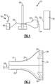
- Figure 1 schematically illustrates a measurement system 10 including an optical height gauge 20.
- the optical height gauge 20 includes at least one LED array 22 configured to illuminate a surface 32 that is being viewed through the height gauge 20.
- a camera 24 Also included within the height gauge 20 is a camera 24.
- the camera 24 digitally captures the surface 32 and provides a video image signal through a wire 26 to a display system 40.
- the display system 40 can be a personal computer, a television screen, or another device capable of digitally displaying the video image captured by the camera 24.
- the wire 26 can be replaced via any other form of digital communication including wireless transmissions.
- the height gauge 20 is mounted to a precision height stand 50.
- the precision height stand 50 can be a commercially available height stand, or a custom height stand, depending on the specific needs of a given measurement system.
- the precision height stand 50 is configured to be precise to within 0.0005 inches (.0127 mm) in an inches setting or 0.01mm (.00039 inches) in a millimeters setting.
- height stands with greater, or lesser, precision can be utilized depending on the tolerance requirements of the component 30 being viewed.
- the display system 40 allows a user, such as a technician, to view the digitally captured video image using a screen 42.
- the display system 40 can include a user interface configured to run on a dedicated computer 44. After initial installation, the user interface on the computer 44 is configured to control the settings, such as brightness, of the LED arrays 22 and the settings of the camera 24, for each measurement location.
- the display system 40 can include magnification features, a crosshair overlay, and other digital enhancement tools designed to allow the user to more precisely measure features of the surface 32 of the component 30.
- the user can ensure that the same precise measurement is made on each component 30 that is being measured, and variations resulting from different operators taking the measurements are minimized.
- the user utilizes the optical height gauge 20 in combination with the screen 42 to precisely position the optical height gauge 20 at a dividing line between a burnished portions of the surface 32 and an unburnished portion of the surface 32.
- a measurement is then taken along the precision height stand 50, indicating the height of the optical height guide 20.
- the height of the optical height guide directly corresponds to the height on the surface 32 of the border between the burnished and unburnished portion and a precise measurement of the surface 32 is acquired.
- the computer 44 can include software allowing the user to record multiple measurements of a given component 30, and generate an inspection report including all relevant measurements.
- the computer 44 can automatically transmit the inspection report to a quality recording system, a process control reporting system, or any other system.
- FIG. 2 schematically illustrates the exemplary height gauge 20 of Figure 1 in greater detail, and removed from the context of the measurement system 10.
- a housing includes a top portion 21 and a bottom portion 23.
- the housing encompasses a camera 24, and multiple LED arrays 22.
- a grommet 28 is disposed on an end of the housing, and assists in maintaining the relative positions of the two housing portions 21, 23.
- the grommet 28 can include a clear lens, thereby sealing the housing.
- Figure 3 schematically illustrates an exploded view of an exemplary optical height gauge 200, such as the height gauge 20 of Figures 1 and 2 .
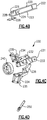
- Figures 4A-4D schematically illustrate a housing 210 ( Figure 4A ), mounting bar 220 ( Figure 4B ), mounting bracket 230 and camera mount 240 ( Figure 4C ) and the tilt bar 250 ( Figure 4D ) isolated from the remainder of the optical height gauge 200.
- the housing 210 includes two housing portions 212, and a grommet 214.
- the grommet 214 includes an opening 216.
- a clear lens is included at the opening, thereby allowing the housing to be completely sealed against environmental conditions.
- the exemplary housing portions 212 are connected via multiple press fit posts included in connector features 218. In alternative examples, any other connection capable of at least partially joining the two housing portions 212 can be utilized in place of the press fit connector features 218.
- Each of the housing portions 212 includes a rear opening 211. The rear openings 211 combine, in an assembled state, to provide a through hole allowing an adjustor knob 232 connected to the mounting bracket 230 to pass through the housing 210.
- the mounting bar 220 connects at a first end 222 to the precision height stand 50 (see Figure 1 ), and includes interconnect features 224, 226 at a second end 228 for interconnecting with the mounting bracket 230. Also included at the second end 228, is a tilt surface 221.
- the tilt surface 221 is angled relative to a length 223 of the mounting bar 220.
- the tilt surface 221 interfaces with a tilt bar 250 within the optical height gauge 200 and is configured to allow the angle of the mounting bracket 230, relative to the mounting bar 220, to be adjusted.
- the angle can be adjusted by up to seven degrees.
- the angle can be adjusted by a single amount, and positions the mounting bracket 230 at either no angle relative to the mounting bar 220, or a seven degree angle relative to the mounting bar 220.
- the mounting bracket 230 is connected to the mounting bar 220 at a first end 231 via the adjustor knob 232, and is supported by the plate interconnect feature 226.
- the adjustor knob 232 protrudes through a hole 233 in the mounting bracket, and a corresponding hole portion of the interconnect feature 224.
- Supported on an opposite end of the mounting bracket 230 are multiple LED array mounts 234, and a U-shaped fixture 236.
- a camera mount 240 is connected to the U-shaped fixture 236 via any suitable fastener, including screws, bolts, and the like. While illustrated in the instant example as a circular camera mount 240, the camera mount 240 can be any suitable shape for a designated digital camera, depending on the needs of the specific system.
- Each of the LED array mounts 234 includes fastener holes 235 for receiving and mounting a corresponding LED array.
- the LED array mounts 234 are angled to focus the light from the LED arrays at a fixed point directly in front of a camera in the camera mount 240. During operation, the fixed point is positioned on the surface being measured, and the LED arrays provide illumination for the camera. While illustrated in the exemplary embodiment as including two LED array mounts 234, one of skill in the art could modify the structure of the mounting bracket 230 to include one LED array mount 234, three LED array mounts 234, or any number of suitable LED array mounts, depending on the amount of illumination needed for a given application of the optical height gauge.
- the tilt bar 250 is interconnected with the mounting bracket 230, and interfaces with the mounting bar 220.
- the tilt bar 216 is configured to position the mounting bracket 230 aligned with the mounting bar 220 in a first state, and angled relative to the mounting bar 220 in a second state.
- Figures 5A and 5B illustrate the orientation of the mounting bracket 230, relative to the mounting bar 220 in a first state ( Figure 5A ) and a second state ( Figure 5B ). While in the first state, Figure 5A , the tilt bar 250 rests against the tilt surface 221 of the mounting bar 220. In this position, the mounting bracket 230 is maintained in line with the length of the mounting bar 220.
- the knob 232 is loosened by rotating the knob 232, and the mounting bracket returns to the first position via a camming action.
- the tilt bar 250 prevents the mounting bracket 230 from extending beyond the predetermined angle.
- the angle is seven degrees.
- this angle can be altered, by adjusting the relative dimensions of the tilt bar, the tilt surface, and the position of the knob along the length of the mounting bar 220, and depending on the needs of the corresponding system.
- Figure 6 illustrates an exemplary user interface 600, such as could be displayed on the screen 42 of the measurement system 10 of Figure 1 .
- a user operating the measurement system 10 can interact with the user interface using any number of known interfaces including a keyboard, a mouse, a touchscreen, any other known interface tool, or any combination of interface tools.
- Included within the user interface 600 is a set of capture information input fields 610 which allow the user to enter data related to the part being captured and/or the specific dimension being measured. This data can then be utilized to generate an automatic report, or provide information with regards to saved details when the capture is retrieved at a later date.
- the measurement entries 620 display the current measurement details of the optical height gauge 20, and can include pressure on the height gauge, height of a crosshair, leading edge height, or any other determined information. When a measurement is captured, the measurement entries 620 form the detailed measurement and provide the information required by the user.
- the camera control window 630 displays information related to each individual LED 632 within each of the LED arrays 634, as well as details of the camera 636. Through the addition of interface features such as buttons, sliders, text fields, or other programmatic controls, the user can directly control each LED 632 in a given LED array 634 thereby controlling the brightness and focus of the LED arrays 634.
- the video window 640 is a window display that provides a digital view of the image being captured by the camera 24 in the optical height gauge.
- the video window 640 can, in some examples, include a crosshair overlay 642 allowing the user to visually match a centerpoint of the optical height gauge 20 with a line 644 distinguishing between a burnished zone and a non-burnished zone of the part being measured.
- Alternative camera control features including magnification, exposure duration, gain, or other digital enhancement tools can be further included within the video window 640.
- inputs and control signals can be generated by the user interface and provided to the optical height gauge 20 through a communicative coupling, such as the wire 26.
Landscapes
- Physics & Mathematics (AREA)
- General Physics & Mathematics (AREA)
- Engineering & Computer Science (AREA)
- Multimedia (AREA)
- Signal Processing (AREA)
- Length Measuring Devices By Optical Means (AREA)
Abstract
Description
- The present disclosure relates generally to optical height gauges, and more specifically to a precision optical height gauge.
- Manufactured components, such as hollow fan blades for utilization in an aircraft, are often constructed under tight tolerances. In some examples, finishing processes during manufacturing are applied to only a portion of the component. In such examples, it is important to ensure that the locations of the finishing on the component are within the specified tolerances. By way of example, some components including the above mentioned hollow fan blades can utilize burnishing with a tight dimensional tolerance on the location of the burnishing.
- In order to ensure that completed components fall within the tight dimensional tolerances, the completed components are manually measured using a gauge and visual inspection. Existing processes for performing the manual measurements are challenging, time intensive, and in some cases inaccurate.
- An optical height gauge according to one disclosed non-limiting embodiment includes a housing, a mounting bar coupled to, and maintained partially in, the housing, a mounting bracket connected to the mounting bar, the mounting bracket including at least one light source holder, a camera mount connected to the mounting bracket, and a tilt bar connected to the mounting bracket and contacting the mounting bar.
- In an embodiment according to the previous embodiment, the mounting bracket is connected to the mounting bar via a pivoting knob shaft.
- In another embodiment according to any of the previous embodiments the tilt bar has a first orientation and a second orientation, and where the mounting bracket is angled relative to the length of the mounting bar while the tilt bar is in the second orientation.
- In another embodiment according to any of the previous embodiments, the mounting bracket is angled approximately seven degrees relative to the length of the mounting bar while the tilt bar is in the second orientation.
- In another embodiment according to any of the previous embodiments, the housing comprises two components joined via at least one press fit connector.
- In another embodiment according to any of the previous embodiments, the mounting bracket includes two light source holders.
- In another embodiment according to any of the previous embodiments, the camera mount is disposed between the light source holders.
- An embodiment according to any of the previous embodiments, further includes a video camera mounted in the camera mount, the video camera being connected to a remote display.
- In another embodiment according to any of the previous embodiments, the remote display includes a computer and a monitor, the computer including a memory storing instructions for operating an auxiliary data acquisition system and for operating a user interface control for the video camera.
- In another embodiment according to any of the previous embodiments, the mounting bar is connected to a precision height stand.
- In another embodiment according to any of the previous embodiments, the precision height stand is precise to at least within 0.0005 inch (.0127 mm) in an inches setting or 0.01mm (.00039 inches) in a millimeters setting.
- A measurement system according to another disclosed non-limiting embodiment includes an optical height gauge having a housing, a mounting bar coupled to, and maintained partially in, the housing, a mounting bracket connected to the mounting bar, the mounting bracket including at least one light source holder, a camera mount connected to the mounting bracket, and a tilt bar connected to the mounting bracket and contacting the mounting bar, a precision height stand, wherein the optical height gauge is mounted to the precision height stand, and a video camera disposed in the camera mount, and communicatively coupled to a computer system.
- An embodiment further includes at least one LED array disposed in the at least one light source holder, wherein the at least one LED array is configured to illuminate a focal point of the camera.
- In another embodiment according to any of the previous embodiments, the computer system includes a control module configured to control camera functions of the camera.
- In another embodiment according to any of the previous embodiments, the camera functions include digital enhancement tools.
- In another embodiment according to any of the previous embodiments, the computer system includes a display and a user interface configured to allow a user to operate the camera.
- In another embodiment according to any of the previous embodiments, the user interface includes a digital image window and a crosshair overlay is positioned in the digital image window.
- A method for determining a height measurement according to another disclosed non-limiting embodiment includes magnifying a digital image provided by an optical height gauge using a user interface, identifying a precise height on a surface in the magnified digital image using the optical height gauge, and capturing the measurement using a computer system communicatively coupled to the optical height gauge.
- In an embodiment according to the above embodiment, the optical height gauge includes a housing, a mounting bar coupled to, and maintained partially in, the housing, a mounting bracket connected to the mounting bar, the mounting bracket including at least one LED array holder, a camera mount connected to the mounting bracket, and a tilt bar connected to the mounting bracket and contacting the mounting bar.
- Another embodiment according to any of the previous embodiments further includes angling the optical height gauge relative to a mounting bar using a tilt bar interfaced with a mounting bracket and the mounting bar.
- These and other features of the present invention can be best understood from the following specification and drawings, the following of which is a brief description.
-
-
Figure 1 schematically illustrates a measurement system including an optical height gauge. -
Figure 2 schematically illustrates the optical height gauge ofFigure 1 , isolated from the measurement system. -
Figure 3 schematically illustrates an exploded view of the optical height gauge. -
Figure 4A schematically illustrates a housing portion of an optical height gauge. -
Figure 4B schematically illustrates a mounting bar of an optical height gauge. -
Figure 4C schematically illustrates a mounting bracket of an optical height gauge. -
Figure 4D schematically illustrates a tilt bar of an optical height gauge. -
Figure 5A schematically illustrates an optical height gauge while a tilt bar is in a first position. -
Figure 5B schematically illustrates an optical height gauge while a tilt bar is in a second position. -
Figure 6 schematically illustrates an exemplary user interface for the measurement system ofFigure 1 . -
Figure 1 schematically illustrates ameasurement system 10 including anoptical height gauge 20. Theoptical height gauge 20 includes at least oneLED array 22 configured to illuminate asurface 32 that is being viewed through theheight gauge 20. Also included within theheight gauge 20 is acamera 24. Thecamera 24 digitally captures thesurface 32 and provides a video image signal through awire 26 to adisplay system 40. By way of example, thedisplay system 40 can be a personal computer, a television screen, or another device capable of digitally displaying the video image captured by thecamera 24. In alternate examples, thewire 26 can be replaced via any other form of digital communication including wireless transmissions. - The
height gauge 20 is mounted to aprecision height stand 50. Theprecision height stand 50 can be a commercially available height stand, or a custom height stand, depending on the specific needs of a given measurement system. In some examples, theprecision height stand 50 is configured to be precise to within 0.0005 inches (.0127 mm) in an inches setting or 0.01mm (.00039 inches) in a millimeters setting. In alternative examples, height stands with greater, or lesser, precision can be utilized depending on the tolerance requirements of thecomponent 30 being viewed. - The
display system 40 allows a user, such as a technician, to view the digitally captured video image using ascreen 42. Thedisplay system 40 can include a user interface configured to run on adedicated computer 44. After initial installation, the user interface on thecomputer 44 is configured to control the settings, such as brightness, of theLED arrays 22 and the settings of thecamera 24, for each measurement location. Thedisplay system 40 can include magnification features, a crosshair overlay, and other digital enhancement tools designed to allow the user to more precisely measure features of thesurface 32 of thecomponent 30. - By using the
optical height gauge 20 on aprecision height stand 50, the user can ensure that the same precise measurement is made on eachcomponent 30 that is being measured, and variations resulting from different operators taking the measurements are minimized. In one exemplary embodiment, the user utilizes theoptical height gauge 20 in combination with thescreen 42 to precisely position theoptical height gauge 20 at a dividing line between a burnished portions of thesurface 32 and an unburnished portion of thesurface 32. A measurement is then taken along theprecision height stand 50, indicating the height of theoptical height guide 20. The height of the optical height guide directly corresponds to the height on thesurface 32 of the border between the burnished and unburnished portion and a precise measurement of thesurface 32 is acquired. - Further, the
computer 44 can include software allowing the user to record multiple measurements of a givencomponent 30, and generate an inspection report including all relevant measurements. In further examples, thecomputer 44 can automatically transmit the inspection report to a quality recording system, a process control reporting system, or any other system. - With continued reference to
Figure 1, Figure 2 schematically illustrates theexemplary height gauge 20 ofFigure 1 in greater detail, and removed from the context of themeasurement system 10. In the exemplaryoptical height gauge 20, a housing includes atop portion 21 and abottom portion 23. The housing encompasses acamera 24, andmultiple LED arrays 22. Agrommet 28 is disposed on an end of the housing, and assists in maintaining the relative positions of the twohousing portions grommet 28 can include a clear lens, thereby sealing the housing. - With continued reference to the examples of
Figures 1 and 2 ,Figure 3 schematically illustrates an exploded view of an exemplaryoptical height gauge 200, such as theheight gauge 20 ofFigures 1 and 2 . Further, with reference toFigure 3 ,Figures 4A-4D schematically illustrate a housing 210 (Figure 4A ), mounting bar 220 (Figure 4B ), mountingbracket 230 and camera mount 240 (Figure 4C ) and the tilt bar 250 (Figure 4D ) isolated from the remainder of theoptical height gauge 200. - The
housing 210 includes twohousing portions 212, and agrommet 214. In some examples, thegrommet 214 includes anopening 216. In alternative examples, a clear lens is included at the opening, thereby allowing the housing to be completely sealed against environmental conditions. Theexemplary housing portions 212 are connected via multiple press fit posts included in connector features 218. In alternative examples, any other connection capable of at least partially joining the twohousing portions 212 can be utilized in place of the press fit connector features 218. Each of thehousing portions 212 includes arear opening 211. Therear openings 211 combine, in an assembled state, to provide a through hole allowing anadjustor knob 232 connected to the mountingbracket 230 to pass through thehousing 210. - Extending partially into the
housing 210 is a mountingbar 220. The mountingbar 220 connects at afirst end 222 to the precision height stand 50 (seeFigure 1 ), and includes interconnect features 224, 226 at asecond end 228 for interconnecting with the mountingbracket 230. Also included at thesecond end 228, is atilt surface 221. Thetilt surface 221 is angled relative to alength 223 of the mountingbar 220. Thetilt surface 221 interfaces with atilt bar 250 within theoptical height gauge 200 and is configured to allow the angle of the mountingbracket 230, relative to the mountingbar 220, to be adjusted. In some examples, the angle can be adjusted by up to seven degrees. In yet further examples, the angle can be adjusted by a single amount, and positions the mountingbracket 230 at either no angle relative to the mountingbar 220, or a seven degree angle relative to the mountingbar 220. - The mounting
bracket 230 is connected to the mountingbar 220 at afirst end 231 via theadjustor knob 232, and is supported by theplate interconnect feature 226. Theadjustor knob 232 protrudes through ahole 233 in the mounting bracket, and a corresponding hole portion of theinterconnect feature 224. Supported on an opposite end of the mountingbracket 230 are multiple LED array mounts 234, and aU-shaped fixture 236. Acamera mount 240 is connected to theU-shaped fixture 236 via any suitable fastener, including screws, bolts, and the like. While illustrated in the instant example as acircular camera mount 240, thecamera mount 240 can be any suitable shape for a designated digital camera, depending on the needs of the specific system. - Each of the LED array mounts 234 includes fastener holes 235 for receiving and mounting a corresponding LED array. The LED array mounts 234 are angled to focus the light from the LED arrays at a fixed point directly in front of a camera in the
camera mount 240. During operation, the fixed point is positioned on the surface being measured, and the LED arrays provide illumination for the camera. While illustrated in the exemplary embodiment as including two LED array mounts 234, one of skill in the art could modify the structure of the mountingbracket 230 to include oneLED array mount 234, three LED array mounts 234, or any number of suitable LED array mounts, depending on the amount of illumination needed for a given application of the optical height gauge. - Also included within the
housing 210 is thetilt bar 250. Thetilt bar 250 is interconnected with the mountingbracket 230, and interfaces with the mountingbar 220. Thetilt bar 216 is configured to position the mountingbracket 230 aligned with the mountingbar 220 in a first state, and angled relative to the mountingbar 220 in a second state. - With continued reference to
Figures 3-4D , and with like numerals indicating like elements,Figures 5A and 5B illustrate the orientation of the mountingbracket 230, relative to the mountingbar 220 in a first state (Figure 5A ) and a second state (Figure 5B ). While in the first state,Figure 5A , thetilt bar 250 rests against thetilt surface 221 of the mountingbar 220. In this position, the mountingbracket 230 is maintained in line with the length of the mountingbar 220. When a user, or other height gauge operator, loosens theknob 232, by rotating theknob 232, and tilts thetilt bar 250 to rotate into the second position (Figure 5B ) alongmovement arrows 310, the mountingbracket 230 pivots at theknob 232, causing the bracket to shift upwards. An end surface of the mountingbar 220 prevents thetilt bar 250 from rotating further than illustrated, and limits the angle by which the mountingbracket 230 can be angled. - To return the mounting bracket to the aligned position, the
knob 232 is loosened by rotating theknob 232, and the mounting bracket returns to the first position via a camming action. Upon coming into contact with thetilt surface 221, thetilt bar 250 prevents the mountingbracket 230 from extending beyond the predetermined angle. In the illustrated example, the angle is seven degrees. One of skill in the art will understand that this angle can be altered, by adjusting the relative dimensions of the tilt bar, the tilt surface, and the position of the knob along the length of the mountingbar 220, and depending on the needs of the corresponding system. - With continued reference to
Figures 1-5B ,Figure 6 illustrates anexemplary user interface 600, such as could be displayed on thescreen 42 of themeasurement system 10 ofFigure 1 . A user operating themeasurement system 10 can interact with the user interface using any number of known interfaces including a keyboard, a mouse, a touchscreen, any other known interface tool, or any combination of interface tools. - Included within the
user interface 600 is a set of capture information input fields 610 which allow the user to enter data related to the part being captured and/or the specific dimension being measured. This data can then be utilized to generate an automatic report, or provide information with regards to saved details when the capture is retrieved at a later date. - Also included in the display are
multiple measurement entries 620. Themeasurement entries 620 display the current measurement details of theoptical height gauge 20, and can include pressure on the height gauge, height of a crosshair, leading edge height, or any other determined information. When a measurement is captured, themeasurement entries 620 form the detailed measurement and provide the information required by the user. - Also included in the
user interface 600 is acamera control window 630. Thecamera control window 630 displays information related to eachindividual LED 632 within each of theLED arrays 634, as well as details of thecamera 636. Through the addition of interface features such as buttons, sliders, text fields, or other programmatic controls, the user can directly control eachLED 632 in a givenLED array 634 thereby controlling the brightness and focus of theLED arrays 634. - Also included in the user interface is a
video window 640. Thevideo window 640 is a window display that provides a digital view of the image being captured by thecamera 24 in the optical height gauge. Thevideo window 640 can, in some examples, include acrosshair overlay 642 allowing the user to visually match a centerpoint of theoptical height gauge 20 with aline 644 distinguishing between a burnished zone and a non-burnished zone of the part being measured. Alternative camera control features including magnification, exposure duration, gain, or other digital enhancement tools can be further included within thevideo window 640. - With reference to all the identified features of the
user interface 600, one of skill in the art will understand that the illustrated positions of the various elements are exemplary only and alternative user interfaces re-arranging the positions of the visual elements on the user interface fall within the scope of the present disclosure. - In examples utilizing the above described
user interface 600, inputs and control signals can be generated by the user interface and provided to theoptical height gauge 20 through a communicative coupling, such as thewire 26. - It is further understood that any of the above described concepts can be used alone or in combination with any or all of the other above described concepts. Although an embodiment of this invention has been disclosed, a worker of ordinary skill in this art would recognize that certain modifications would come within the scope of this invention. For that reason, the following claims should be studied to determine the true scope and content of this invention.
Claims (15)
- An optical height gauge (20;200) comprising:a housing (210);a mounting bar (220) coupled to, and maintained partially in, the housing (210);a mounting bracket (130) connected to the mounting bar (220), the mounting bracket (230) including at least one light source holder (234);a camera mount (240) connected to the mounting bracket (230); anda tilt bar (250) connected to said mounting bracket (230) and contacting said mounting bar (220).
- The optical height gauge (20;200) of claim 1, wherein the mounting bracket (230) is connected to the mounting bar (220) via a pivoting knob shaft (232).
- The optical height gauge (20;200) of claim 1 or 2, wherein the tilt bar (250) has a first orientation and a second orientation, and the mounting bracket (230) is angled, for example at approximately seven degrees, relative to the length (223) of the mounting bar (220) while the tilt bar (250) is in the second orientation.
- The optical height gauge (20;200) of any preceding claim, wherein the housing (210) comprises two components (212) joined via at least one press fit connector (218).
- The optical height gauge (20;200) of any preceding claim, wherein the mounting bracket (230) includes two light source holders (234), optionally wherein the camera mount (240) is disposed between the light source holders (234).
- The optical height gauge (20;200) of any preceding claim, further comprising a video camera (24) mounted in said camera mount (240), the video camera (24) being connected to a remote display (40).
- The optical height gauge (20;200) of claim 6, wherein the remote display (40) includes a computer (44) and a monitor (42), the computer (44) including a memory storing instructions for operating an auxiliary data acquisition system and for operating a user interface control for said video camera (24).
- The optical height gauge (20;200) of any preceding claim, wherein the mounting bar (220) is connected to a precision height stand (50), optionally wherein the precision height stand (50) is precise to at least within 0.0005 inches (.0127 mm) in an inches setting or 0.01mm (.00039 inches) in a millimeters setting.
- A measurement system (10) comprising:the optical height gauge (20;200) of any of claims 1 to 5;a precision height stand (50), wherein the optical height gauge (20;200) is mounted to the precision height stand (50); anda video camera (24) disposed in said camera mount (240), and communicatively coupled to a computer (44).
- The measurement system (10) of claim 9, further comprising at least one LED array (22) disposed in said at least one light source holder (234), wherein said at least one LED array (22) is configured to illuminate a focal point of said video camera (24).
- The measurement system (10) of claim 9 or 10, wherein said computer (44) includes a control module configured to control camera functions of said video camera (24), optionally wherein said camera functions include digital enhancement tools.
- The measurement system (10) of claim 9 or 11, wherein said computer (44) includes a display (42) and a user interface (600) configured to allow a user to operate said video camera (24).
- The measurement system (10) of claim 12, wherein said user interface (600) includes a digital image window (640) and a crosshair overlay (642) is positioned in said digital image window (640).
- A method for determining a height measurement comprising:magnifying a digital image provided by an optical height gauge (20;200) using a user interface (600);identifying a precise height on a surface (32) in said magnified digital image using the optical height gauge (20;200); andcapturing the measurement using a computer (44) communicatively coupled to the optical height gauge (20;200).
- The method of claim 14, further comprising angling the optical height gauge (20;200) relative to a mounting bar (220) using a tilt bar (250) interfaced with a mounting bracket (230) and the mounting bar (220).
Applications Claiming Priority (1)
| Application Number | Priority Date | Filing Date | Title |
|---|---|---|---|
| US15/489,852 US10274308B2 (en) | 2017-04-18 | 2017-04-18 | Precision optical height gauge |
Publications (2)
| Publication Number | Publication Date |
|---|---|
| EP3392607A1 true EP3392607A1 (en) | 2018-10-24 |
| EP3392607B1 EP3392607B1 (en) | 2021-06-02 |
Family
ID=62025740
Family Applications (1)
| Application Number | Title | Priority Date | Filing Date |
|---|---|---|---|
| EP18168044.8A Active EP3392607B1 (en) | 2017-04-18 | 2018-04-18 | Precision optical height gauge |
Country Status (2)
| Country | Link |
|---|---|
| US (1) | US10274308B2 (en) |
| EP (1) | EP3392607B1 (en) |
Families Citing this family (1)
| Publication number | Priority date | Publication date | Assignee | Title |
|---|---|---|---|---|
| CN111836000A (en) * | 2019-04-15 | 2020-10-27 | 北京同创达勘测有限公司 | Underground camera |
Citations (4)
| Publication number | Priority date | Publication date | Assignee | Title |
|---|---|---|---|---|
| WO1996030718A1 (en) * | 1995-03-30 | 1996-10-03 | Pipetech Aps | System identification |
| JP2008046103A (en) * | 2006-07-19 | 2008-02-28 | Shimatec:Kk | Surface inspection device |
| US20120062963A1 (en) * | 2009-02-23 | 2012-03-15 | Jason Gregory Gillham | Laser scanner assembly |
| EP2667146A1 (en) * | 2012-05-22 | 2013-11-27 | inos Automationssoftware GmbH | Optical arrangement comprising an optical acquiring unit and a light emitting unit |
Family Cites Families (7)
| Publication number | Priority date | Publication date | Assignee | Title |
|---|---|---|---|---|
| US4037325A (en) | 1975-01-13 | 1977-07-26 | Quality Measurement Systems, Inc. | Linear glass scale height gage |
| JPH0438406A (en) * | 1990-06-04 | 1992-02-07 | Sumitomo Rubber Ind Ltd | Apparatus and method for measuring position of spherical flying object |
| JP4009379B2 (en) | 1999-01-20 | 2007-11-14 | 株式会社ミツトヨ | Height gauge |
| DE602006009625D1 (en) | 2006-04-19 | 2009-11-19 | Tesa Sa | Device for measuring dimensions and vertical column with such a device |
| EP2251634B1 (en) | 2009-05-13 | 2018-11-28 | Tesa Sa | Dimension measuring instrument consisting in a vertical measurement column |
| DE202013004479U1 (en) * | 2013-05-14 | 2014-08-18 | Steinbichler Optotechnik Gmbh | Fixing device for a 3D measuring device |
| US9342743B2 (en) | 2014-06-02 | 2016-05-17 | Tesa Sa | Method for supporting an operator in measuring a part of an object |
-
2017
- 2017-04-18 US US15/489,852 patent/US10274308B2/en active Active
-
2018
- 2018-04-18 EP EP18168044.8A patent/EP3392607B1/en active Active
Patent Citations (4)
| Publication number | Priority date | Publication date | Assignee | Title |
|---|---|---|---|---|
| WO1996030718A1 (en) * | 1995-03-30 | 1996-10-03 | Pipetech Aps | System identification |
| JP2008046103A (en) * | 2006-07-19 | 2008-02-28 | Shimatec:Kk | Surface inspection device |
| US20120062963A1 (en) * | 2009-02-23 | 2012-03-15 | Jason Gregory Gillham | Laser scanner assembly |
| EP2667146A1 (en) * | 2012-05-22 | 2013-11-27 | inos Automationssoftware GmbH | Optical arrangement comprising an optical acquiring unit and a light emitting unit |
Also Published As
| Publication number | Publication date |
|---|---|
| EP3392607B1 (en) | 2021-06-02 |
| US10274308B2 (en) | 2019-04-30 |
| US20180299254A1 (en) | 2018-10-18 |
Similar Documents
| Publication | Publication Date | Title |
|---|---|---|
| US8339464B2 (en) | Universal test system for controlling a plurality of parameters concerning the operation of a device for presenting optoelectronic information of various types | |
| US12293501B2 (en) | Imaging tool for vibration and/or misalignment analysis | |
| EP2597459B2 (en) | Image processing apparatus | |
| EP2464094B1 (en) | Means and method for assisting installation of monitoring camera | |
| CN205898703U (en) | Optical fibre end face surveymeter | |
| CN2914057Y (en) | Camera shooting mould set test bench | |
| EP3392607B1 (en) | Precision optical height gauge | |
| US6778714B1 (en) | Portable image analysis system | |
| CN210221847U (en) | Tablet computer rear cover part missing detection device based on machine vision | |
| US9778450B2 (en) | Microscope accessory | |
| EP1508387B1 (en) | Method and apparatus for aligning equipment in a steel mill | |
| CN106569327B (en) | Endoscope kit and industrial endoscope detection system comprising same | |
| JP6701113B2 (en) | Adapter, microscope adjusting method, microscope system and program | |
| JP4671889B2 (en) | Drilling device and drilling method | |
| KR20070049835A (en) | Camera module focusing device and focusing method | |
| EP3165341A1 (en) | Shaft alignment apparatus and shaft alignment position setting method | |
| KR100200357B1 (en) | Optical characteristic measuring device | |
| KR100946840B1 (en) | Inspection mechanism to fix LCD panel | |
| KR20100000460A (en) | Digital vision tester | |
| CN206235776U (en) | Endoscope set and the industrial endoscope detecting system comprising the endoscope set | |
| JP2010262034A (en) | Cup-mounting device | |
| CN217331564U (en) | Screening device for lens group with optical imaging definition consistency | |
| JP2016082588A (en) | Calibration device of stereoscopic display device | |
| TWI712779B (en) | Multifunctional gear detection system | |
| CN222317991U (en) | Flow Chi Duizhong tool |
Legal Events
| Date | Code | Title | Description |
|---|---|---|---|
| PUAI | Public reference made under article 153(3) epc to a published international application that has entered the european phase |
Free format text: ORIGINAL CODE: 0009012 |
|
| STAA | Information on the status of an ep patent application or granted ep patent |
Free format text: STATUS: THE APPLICATION HAS BEEN PUBLISHED |
|
| AK | Designated contracting states |
Kind code of ref document: A1 Designated state(s): AL AT BE BG CH CY CZ DE DK EE ES FI FR GB GR HR HU IE IS IT LI LT LU LV MC MK MT NL NO PL PT RO RS SE SI SK SM TR |
|
| AX | Request for extension of the european patent |
Extension state: BA ME |
|
| STAA | Information on the status of an ep patent application or granted ep patent |
Free format text: STATUS: REQUEST FOR EXAMINATION WAS MADE |
|
| 17P | Request for examination filed |
Effective date: 20190424 |
|
| RBV | Designated contracting states (corrected) |
Designated state(s): AL AT BE BG CH CY CZ DE DK EE ES FI FR GB GR HR HU IE IS IT LI LT LU LV MC MK MT NL NO PL PT RO RS SE SI SK SM TR |
|
| STAA | Information on the status of an ep patent application or granted ep patent |
Free format text: STATUS: EXAMINATION IS IN PROGRESS |
|
| 17Q | First examination report despatched |
Effective date: 20190614 |
|
| GRAP | Despatch of communication of intention to grant a patent |
Free format text: ORIGINAL CODE: EPIDOSNIGR1 |
|
| STAA | Information on the status of an ep patent application or granted ep patent |
Free format text: STATUS: GRANT OF PATENT IS INTENDED |
|
| INTG | Intention to grant announced |
Effective date: 20201125 |
|
| RAP1 | Party data changed (applicant data changed or rights of an application transferred) |
Owner name: RAYTHEON TECHNOLOGIES CORPORATION |
|
| GRAS | Grant fee paid |
Free format text: ORIGINAL CODE: EPIDOSNIGR3 |
|
| GRAA | (expected) grant |
Free format text: ORIGINAL CODE: 0009210 |
|
| STAA | Information on the status of an ep patent application or granted ep patent |
Free format text: STATUS: THE PATENT HAS BEEN GRANTED |
|
| REG | Reference to a national code |
Ref country code: CH Ref legal event code: EP |
|
| AK | Designated contracting states |
Kind code of ref document: B1 Designated state(s): AL AT BE BG CH CY CZ DE DK EE ES FI FR GB GR HR HU IE IS IT LI LT LU LV MC MK MT NL NO PL PT RO RS SE SI SK SM TR |
|
| REG | Reference to a national code |
Ref country code: GB Ref legal event code: FG4D |
|
| REG | Reference to a national code |
Ref country code: AT Ref legal event code: REF Ref document number: 1398863 Country of ref document: AT Kind code of ref document: T Effective date: 20210615 |
|
| REG | Reference to a national code |
Ref country code: IE Ref legal event code: FG4D |
|
| REG | Reference to a national code |
Ref country code: DE Ref legal event code: R096 Ref document number: 602018017891 Country of ref document: DE |
|
| REG | Reference to a national code |
Ref country code: LT Ref legal event code: MG9D |
|
| PG25 | Lapsed in a contracting state [announced via postgrant information from national office to epo] |
Ref country code: BG Free format text: LAPSE BECAUSE OF FAILURE TO SUBMIT A TRANSLATION OF THE DESCRIPTION OR TO PAY THE FEE WITHIN THE PRESCRIBED TIME-LIMIT Effective date: 20210902 Ref country code: HR Free format text: LAPSE BECAUSE OF FAILURE TO SUBMIT A TRANSLATION OF THE DESCRIPTION OR TO PAY THE FEE WITHIN THE PRESCRIBED TIME-LIMIT Effective date: 20210602 Ref country code: LT Free format text: LAPSE BECAUSE OF FAILURE TO SUBMIT A TRANSLATION OF THE DESCRIPTION OR TO PAY THE FEE WITHIN THE PRESCRIBED TIME-LIMIT Effective date: 20210602 Ref country code: FI Free format text: LAPSE BECAUSE OF FAILURE TO SUBMIT A TRANSLATION OF THE DESCRIPTION OR TO PAY THE FEE WITHIN THE PRESCRIBED TIME-LIMIT Effective date: 20210602 |
|
| REG | Reference to a national code |
Ref country code: NL Ref legal event code: MP Effective date: 20210602 |
|
| REG | Reference to a national code |
Ref country code: AT Ref legal event code: MK05 Ref document number: 1398863 Country of ref document: AT Kind code of ref document: T Effective date: 20210602 |
|
| PG25 | Lapsed in a contracting state [announced via postgrant information from national office to epo] |
Ref country code: GR Free format text: LAPSE BECAUSE OF FAILURE TO SUBMIT A TRANSLATION OF THE DESCRIPTION OR TO PAY THE FEE WITHIN THE PRESCRIBED TIME-LIMIT Effective date: 20210903 Ref country code: LV Free format text: LAPSE BECAUSE OF FAILURE TO SUBMIT A TRANSLATION OF THE DESCRIPTION OR TO PAY THE FEE WITHIN THE PRESCRIBED TIME-LIMIT Effective date: 20210602 Ref country code: NO Free format text: LAPSE BECAUSE OF FAILURE TO SUBMIT A TRANSLATION OF THE DESCRIPTION OR TO PAY THE FEE WITHIN THE PRESCRIBED TIME-LIMIT Effective date: 20210902 Ref country code: PL Free format text: LAPSE BECAUSE OF FAILURE TO SUBMIT A TRANSLATION OF THE DESCRIPTION OR TO PAY THE FEE WITHIN THE PRESCRIBED TIME-LIMIT Effective date: 20210602 Ref country code: SE Free format text: LAPSE BECAUSE OF FAILURE TO SUBMIT A TRANSLATION OF THE DESCRIPTION OR TO PAY THE FEE WITHIN THE PRESCRIBED TIME-LIMIT Effective date: 20210602 Ref country code: RS Free format text: LAPSE BECAUSE OF FAILURE TO SUBMIT A TRANSLATION OF THE DESCRIPTION OR TO PAY THE FEE WITHIN THE PRESCRIBED TIME-LIMIT Effective date: 20210602 |
|
| PG25 | Lapsed in a contracting state [announced via postgrant information from national office to epo] |
Ref country code: SM Free format text: LAPSE BECAUSE OF FAILURE TO SUBMIT A TRANSLATION OF THE DESCRIPTION OR TO PAY THE FEE WITHIN THE PRESCRIBED TIME-LIMIT Effective date: 20210602 Ref country code: SK Free format text: LAPSE BECAUSE OF FAILURE TO SUBMIT A TRANSLATION OF THE DESCRIPTION OR TO PAY THE FEE WITHIN THE PRESCRIBED TIME-LIMIT Effective date: 20210602 Ref country code: ES Free format text: LAPSE BECAUSE OF FAILURE TO SUBMIT A TRANSLATION OF THE DESCRIPTION OR TO PAY THE FEE WITHIN THE PRESCRIBED TIME-LIMIT Effective date: 20210602 Ref country code: EE Free format text: LAPSE BECAUSE OF FAILURE TO SUBMIT A TRANSLATION OF THE DESCRIPTION OR TO PAY THE FEE WITHIN THE PRESCRIBED TIME-LIMIT Effective date: 20210602 Ref country code: NL Free format text: LAPSE BECAUSE OF FAILURE TO SUBMIT A TRANSLATION OF THE DESCRIPTION OR TO PAY THE FEE WITHIN THE PRESCRIBED TIME-LIMIT Effective date: 20210602 Ref country code: PT Free format text: LAPSE BECAUSE OF FAILURE TO SUBMIT A TRANSLATION OF THE DESCRIPTION OR TO PAY THE FEE WITHIN THE PRESCRIBED TIME-LIMIT Effective date: 20211004 Ref country code: RO Free format text: LAPSE BECAUSE OF FAILURE TO SUBMIT A TRANSLATION OF THE DESCRIPTION OR TO PAY THE FEE WITHIN THE PRESCRIBED TIME-LIMIT Effective date: 20210602 Ref country code: CZ Free format text: LAPSE BECAUSE OF FAILURE TO SUBMIT A TRANSLATION OF THE DESCRIPTION OR TO PAY THE FEE WITHIN THE PRESCRIBED TIME-LIMIT Effective date: 20210602 Ref country code: AT Free format text: LAPSE BECAUSE OF FAILURE TO SUBMIT A TRANSLATION OF THE DESCRIPTION OR TO PAY THE FEE WITHIN THE PRESCRIBED TIME-LIMIT Effective date: 20210602 |
|
| REG | Reference to a national code |
Ref country code: DE Ref legal event code: R097 Ref document number: 602018017891 Country of ref document: DE |
|
| PLBE | No opposition filed within time limit |
Free format text: ORIGINAL CODE: 0009261 |
|
| STAA | Information on the status of an ep patent application or granted ep patent |
Free format text: STATUS: NO OPPOSITION FILED WITHIN TIME LIMIT |
|
| PG25 | Lapsed in a contracting state [announced via postgrant information from national office to epo] |
Ref country code: DK Free format text: LAPSE BECAUSE OF FAILURE TO SUBMIT A TRANSLATION OF THE DESCRIPTION OR TO PAY THE FEE WITHIN THE PRESCRIBED TIME-LIMIT Effective date: 20210602 |
|
| 26N | No opposition filed |
Effective date: 20220303 |
|
| PG25 | Lapsed in a contracting state [announced via postgrant information from national office to epo] |
Ref country code: AL Free format text: LAPSE BECAUSE OF FAILURE TO SUBMIT A TRANSLATION OF THE DESCRIPTION OR TO PAY THE FEE WITHIN THE PRESCRIBED TIME-LIMIT Effective date: 20210602 |
|
| PG25 | Lapsed in a contracting state [announced via postgrant information from national office to epo] |
Ref country code: IT Free format text: LAPSE BECAUSE OF FAILURE TO SUBMIT A TRANSLATION OF THE DESCRIPTION OR TO PAY THE FEE WITHIN THE PRESCRIBED TIME-LIMIT Effective date: 20210602 |
|
| REG | Reference to a national code |
Ref country code: CH Ref legal event code: PL |
|
| REG | Reference to a national code |
Ref country code: BE Ref legal event code: MM Effective date: 20220430 |
|
| PG25 | Lapsed in a contracting state [announced via postgrant information from national office to epo] |
Ref country code: MC Free format text: LAPSE BECAUSE OF FAILURE TO SUBMIT A TRANSLATION OF THE DESCRIPTION OR TO PAY THE FEE WITHIN THE PRESCRIBED TIME-LIMIT Effective date: 20210602 Ref country code: LU Free format text: LAPSE BECAUSE OF NON-PAYMENT OF DUE FEES Effective date: 20220418 Ref country code: LI Free format text: LAPSE BECAUSE OF NON-PAYMENT OF DUE FEES Effective date: 20220430 Ref country code: CH Free format text: LAPSE BECAUSE OF NON-PAYMENT OF DUE FEES Effective date: 20220430 |
|
| PG25 | Lapsed in a contracting state [announced via postgrant information from national office to epo] |
Ref country code: BE Free format text: LAPSE BECAUSE OF NON-PAYMENT OF DUE FEES Effective date: 20220430 |
|
| PG25 | Lapsed in a contracting state [announced via postgrant information from national office to epo] |
Ref country code: IE Free format text: LAPSE BECAUSE OF NON-PAYMENT OF DUE FEES Effective date: 20220418 |
|
| P01 | Opt-out of the competence of the unified patent court (upc) registered |
Effective date: 20230521 |
|
| PG25 | Lapsed in a contracting state [announced via postgrant information from national office to epo] |
Ref country code: HU Free format text: LAPSE BECAUSE OF FAILURE TO SUBMIT A TRANSLATION OF THE DESCRIPTION OR TO PAY THE FEE WITHIN THE PRESCRIBED TIME-LIMIT; INVALID AB INITIO Effective date: 20180418 |
|
| PG25 | Lapsed in a contracting state [announced via postgrant information from national office to epo] |
Ref country code: MK Free format text: LAPSE BECAUSE OF FAILURE TO SUBMIT A TRANSLATION OF THE DESCRIPTION OR TO PAY THE FEE WITHIN THE PRESCRIBED TIME-LIMIT Effective date: 20210602 Ref country code: CY Free format text: LAPSE BECAUSE OF FAILURE TO SUBMIT A TRANSLATION OF THE DESCRIPTION OR TO PAY THE FEE WITHIN THE PRESCRIBED TIME-LIMIT Effective date: 20210602 |
|
| PG25 | Lapsed in a contracting state [announced via postgrant information from national office to epo] |
Ref country code: TR Free format text: LAPSE BECAUSE OF FAILURE TO SUBMIT A TRANSLATION OF THE DESCRIPTION OR TO PAY THE FEE WITHIN THE PRESCRIBED TIME-LIMIT Effective date: 20210602 |
|
| PG25 | Lapsed in a contracting state [announced via postgrant information from national office to epo] |
Ref country code: MT Free format text: LAPSE BECAUSE OF FAILURE TO SUBMIT A TRANSLATION OF THE DESCRIPTION OR TO PAY THE FEE WITHIN THE PRESCRIBED TIME-LIMIT Effective date: 20210602 |
|
| PGFP | Annual fee paid to national office [announced via postgrant information from national office to epo] |
Ref country code: DE Payment date: 20250319 Year of fee payment: 8 |
|
| REG | Reference to a national code |
Ref country code: DE Ref legal event code: R081 Ref document number: 602018017891 Country of ref document: DE Owner name: RTX CORPORATION (N.D.GES.D. STAATES DELAWARE),, US Free format text: FORMER OWNER: RAYTHEON TECHNOLOGIES CORPORATION, FARMINGTON, CT, US |
|
| PGFP | Annual fee paid to national office [announced via postgrant information from national office to epo] |
Ref country code: GB Payment date: 20260319 Year of fee payment: 9 |
|
| PGFP | Annual fee paid to national office [announced via postgrant information from national office to epo] |
Ref country code: FR Payment date: 20260320 Year of fee payment: 9 |