EP3392605A1 - Trolley wire measuring apparatus and trolley wire measuring method - Google Patents
Trolley wire measuring apparatus and trolley wire measuring method Download PDFInfo
- Publication number
- EP3392605A1 EP3392605A1 EP15910690.5A EP15910690A EP3392605A1 EP 3392605 A1 EP3392605 A1 EP 3392605A1 EP 15910690 A EP15910690 A EP 15910690A EP 3392605 A1 EP3392605 A1 EP 3392605A1
- Authority
- EP
- European Patent Office
- Prior art keywords
- wire
- point
- trolley
- railway
- height
- Prior art date
- Legal status (The legal status is an assumption and is not a legal conclusion. Google has not performed a legal analysis and makes no representation as to the accuracy of the status listed.)
- Granted
Links
Images











Classifications
-
- G—PHYSICS
- G01—MEASURING; TESTING
- G01B—MEASURING LENGTH, THICKNESS OR SIMILAR LINEAR DIMENSIONS; MEASURING ANGLES; MEASURING AREAS; MEASURING IRREGULARITIES OF SURFACES OR CONTOURS
- G01B11/00—Measuring arrangements characterised by the use of optical techniques
- G01B11/002—Measuring arrangements characterised by the use of optical techniques for measuring two or more coordinates
-
- B—PERFORMING OPERATIONS; TRANSPORTING
- B60—VEHICLES IN GENERAL
- B60M—POWER SUPPLY LINES, AND DEVICES ALONG RAILS, FOR ELECTRICALLY- PROPELLED VEHICLES
- B60M1/00—Power supply lines for contact with collector on vehicle
- B60M1/12—Trolley lines; Accessories therefor
- B60M1/13—Trolley wires
-
- B—PERFORMING OPERATIONS; TRANSPORTING
- B60—VEHICLES IN GENERAL
- B60M—POWER SUPPLY LINES, AND DEVICES ALONG RAILS, FOR ELECTRICALLY- PROPELLED VEHICLES
- B60M1/00—Power supply lines for contact with collector on vehicle
- B60M1/12—Trolley lines; Accessories therefor
- B60M1/28—Manufacturing or repairing trolley lines
-
- B—PERFORMING OPERATIONS; TRANSPORTING
- B61—RAILWAYS
- B61L—GUIDING RAILWAY TRAFFIC; ENSURING THE SAFETY OF RAILWAY TRAFFIC
- B61L23/00—Control, warning or like safety means along the route or between vehicles or trains
- B61L23/04—Control, warning or like safety means along the route or between vehicles or trains for monitoring the mechanical state of the route
- B61L23/042—Track changes detection
-
- G—PHYSICS
- G01—MEASURING; TESTING
- G01B—MEASURING LENGTH, THICKNESS OR SIMILAR LINEAR DIMENSIONS; MEASURING ANGLES; MEASURING AREAS; MEASURING IRREGULARITIES OF SURFACES OR CONTOURS
- G01B11/00—Measuring arrangements characterised by the use of optical techniques
- G01B11/24—Measuring arrangements characterised by the use of optical techniques for measuring contours or curvatures
- G01B11/245—Measuring arrangements characterised by the use of optical techniques for measuring contours or curvatures using a plurality of fixed, simultaneously operating transducers
-
- G—PHYSICS
- G01—MEASURING; TESTING
- G01B—MEASURING LENGTH, THICKNESS OR SIMILAR LINEAR DIMENSIONS; MEASURING ANGLES; MEASURING AREAS; MEASURING IRREGULARITIES OF SURFACES OR CONTOURS
- G01B21/00—Measuring arrangements or details thereof, where the measuring technique is not covered by the other groups of this subclass, unspecified or not relevant
- G01B21/16—Measuring arrangements or details thereof, where the measuring technique is not covered by the other groups of this subclass, unspecified or not relevant for measuring distance of clearance between spaced objects
-
- G—PHYSICS
- G01—MEASURING; TESTING
- G01B—MEASURING LENGTH, THICKNESS OR SIMILAR LINEAR DIMENSIONS; MEASURING ANGLES; MEASURING AREAS; MEASURING IRREGULARITIES OF SURFACES OR CONTOURS
- G01B21/00—Measuring arrangements or details thereof, where the measuring technique is not covered by the other groups of this subclass, unspecified or not relevant
- G01B21/20—Measuring arrangements or details thereof, where the measuring technique is not covered by the other groups of this subclass, unspecified or not relevant for measuring contours or curvatures, e.g. determining profile
Definitions
- the present invention relates to a trolley-wire measurement device and a trolley-wire measurement method for measuring the position of a trolley wire.
- Patent Literature 1 discloses a technique for determining that relatively low points of measured points within a set range are a trolley wire candidate to calculate coordinate values of the trolley wire on the basis of the installation conditions of the trolley wire and the speed of a vehicle with a measurement device mounted thereon.
- Patent Literature 1 Japanese Patent Application No. 2010-243416
- the present invention has been achieved to solve the above problems, and an object of the present invention is to provide a trolley-wire measurement device that is capable of measuring a height and a displacement of a trolley wire relative to a reference set on a railway.
- the present invention provides a trolley-wire measurement device comprising: a rail detection unit to detect rails from point-group data that is an aggregate of points obtained by measuring a target object three-dimensionally, the rails defining a railway on which a train runs; a reference setting unit to set a reference for measuring a height and a displacement of a point on a trolley wire on a basis of the rails detected; a trolley-wire detection unit to detect the point on the trolley wire from the point-group data; and a height and displacement measurement unit to measure the height and the displacement of the point on the trolley wire by using the reference.
- the present invention provides an effect of measuring the height and the displacement of the trolley wire relative to the reference set on the railway.
- FIG. 1 is a block diagram illustrating a configuration example of a trolley-wire measurement device 1 according to a first embodiment of the present invention.
- the trolley-wire measurement device 1 measures the position of a trolley wire relative to a reference that is set on the basis of the position of rails that define a railway on which a train runs. Specifically, the trolley-wire measurement device 1 measures a height and a displacement of a trolley wire.
- the trolley-wire measurement device 1 includes a storage unit 10, a railway measurement unit 20, a trolley-wire detection unit 30, and a height and displacement measurement unit 40.
- the storage unit 10 stores point-group data 11 therein.
- the point-group data 11 which is an aggregate of points having three-dimensional coordinate values, is a result of a three-dimensional measurement of a target object such as a trolley wire, a messenger wire, and a rail.
- the point-group data 11 refers to data expressed in terms of coordinate values of the points measured three-dimensionally by a measuring device using a laser scanner, a camera, a GPS antenna, and the like.
- the point-group data 11 is data on points measured three-dimensionally by the measuring device such as a Mobile Mapping System (MMS).
- MMS Mobile Mapping System
- the point-group data 11 is not limited thereto. FIG.
- FIG. 2 is a diagram illustrating an example of a three-dimensionally measured target object that is expressed by the point-group data 11 stored in the storage unit 10 according to the first embodiment.
- the scope of the three-dimensionally measured target object expressed by the point-group data 11 is defined as including rails 101 laid on the ground, a trolley wire 102 hanging in the air, a messenger wire 103 suspending the trolley wire 102, and the like.
- One point P i of a point group 104 of the three-dimensionally measured target object can be expressed as P i (x i , y i , z i ) by using three-axis coordinate values in the x-axis direction, the y-axis direction, and the z-axis direction.
- FIG. 3 is a diagram illustrating a configuration example of the point-group data 11 stored in the storage unit 10 according to the first embodiment.
- the storage unit 10 stores therein the point-group data 11 that is defined by the data on three-axis coordinate values of points P 1 to P K including the aforementioned point P i in the x-axis direction, the y-axis direction, and the z-axis direction.
- the x-axis direction, the y-axis direction, and the z-axis direction can be defined, for example, using a plane rectangular coordinate system such that the xy-axis is in the horizontal plane and the z-axis is oriented in the height direction.
- a coordinate system may be employed which has an origin at any point and defines, for example, the eastward direction as the x-axis direction, the northward direction as the y-axis direction, and the vertically upward direction as the z-axis direction.
- the unit indicating the data on the coordinate values of each point can be, but not limited to, meters (m) or the like.
- the railway measurement unit 20 includes a rail detection unit 21 and a reference setting unit 22.
- the rail detection unit 21 detects the rail 101 from the point-group data 11 stored in the storage unit 10. For example, the rail detection unit 21 extracts from the point-group data 11 the point group 104 defined by a plurality of points, and then detects the rail 101 by performing matching between the shape expressed by the extracted point group 104 and a template 105 that is an aggregate of points taking the shape of the rail 101.
- FIG. 4 is a conceptual diagram illustrating a process of detecting the rail 101 in the rail detection unit 21 according to the first embodiment. As illustrated in FIG. 4 , the rail detection unit 21 detects that there is the rail 101 at the position of the point group 104 that matches the shape of the template 105.
- the reference setting unit 22 sets a reference for measurement of the height and the displacement of the point on the trolley wire 102. Specifically, on the basis of the rails 101 detected by the rail detection unit 21, the reference setting unit 22 derives a rail plane which is a plane connecting respective top surfaces of the detected, two, left and right rails 101, that is, the reference setting unit 22 derives the rail plane that is a plane including the surfaces which a train contacts.
- FIG. 5 is a conceptual diagram illustrating a process of deriving a rail plane 106 in the reference setting unit 22 according to the first embodiment. As illustrated in FIG.
- the reference setting unit 22 sets the rail plane 106 that is the plane connecting the respective top surfaces of the two, left and right rails 101.
- the reference setting unit 22 may compute to thereby derive the rail surface 106 from the point-group data 11 illustrated in FIG. 3 without drawing the rails 101 as illustrated in FIG. 5 .
- the reference setting unit 22 derives from the rail plane 106 a railway center line positioned at the center between the two left and right side rails 101.
- FIG. 6 is a conceptual diagram illustrating a process of deriving a railway center line 109 in the reference setting unit 22 according to the first embodiment.
- the reference setting unit 22 sets rail points 107 at positions on the inner sides of the top portions of the two, left and right ones of the rails 101 detected by the rail detection unit 21.
- the reference setting unit 22 derives a rail line 108 connecting the rail points 107 of each of the left and right rails 101 by, for example, least squares approximation of the rail points 107.
- the reference setting unit 22 then derives the railway center line 109 that is a line positioned at the center between the respective derived rail lines 108 of the left and right rails 101.
- the railway center line 109 is equally distant from each of the rails 101.
- the positions of the rail points 107 are not limited to the inner sides of the top portions of the two, left and right rails 101, but may be the outer sides of the top portions of the two, left and right rails 101.
- the rail points 107 indicate particular positions on the rail 101 detected by the rail detection unit 21.
- the rail points 107 indicate the positions on the inner sides of the top portions of the two left and right rails 101.
- the detection process in the rail detection unit 21 provides the coordinate values of the rail points 107 for the corrected location at which the rail 101 should be disposed relative to the live measured point-group data stored in the point-group data 11.
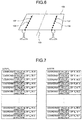
- FIG. 7 is a diagram illustrating an example of the data on the rail points 107 held in the rail detection unit 21 according to the first embodiment.
- the rail detection unit 21 holds therein the data on the rail points 107 illustrated in FIG. 7 .
- the reference setting unit 22 uses the data on the rail points 107 illustrated in FIG. 7 . As illustrated in FIGS.
- the rail detection unit 21 detects the two rails 101 per railway that are the left and right rails 101 in this example, and holds the data on rail points 107L i of the left-side rail 101 and the data on rail points 107R i of the right-side rail 101.
- FIG. 8 is a diagram illustrating how a railway center plane 110 derived by the reference setting unit 22 relates to the rail plane 106 and the railway center line 109 according to the first embodiment.
- the rail plane 106, the railway center line 109, and the railway center plane 110 are added to the illustrations in FIG. 2 .
- the reference setting unit 22 outputs the derived rail plane 106 and the derived railway center plane 110 as a first reference and a second reference, respectively, to the height and displacement measurement unit 40.
- the trolley-wire detection unit 30 detects points on the trolley wire 102 from the point-group data 11 stored in the storage unit 10.
- the trolley-wire detection unit 30 is capable of performing a process of detecting points on the trolley wire 102 on all of the pieces of point-group data 11 stored in the storage unit 10.
- a detection process for all of the pieces of point-group data increases the processing amount for detecting the points on the trolley wire 102.
- the trolley-wire detection unit 30 defines a specified range at a certain height or greater as an area of the point group 104 that is to be extracted.
- the lateral extraction area may be limited using information on the track of a vehicle having the measuring device mounted thereon at the time of the previous measurement, and information on the rail position.
- the position of the trolley wire 102 is defined such that the height of the trolley wire from the rail plane 106 falls within a specified range, and that the displacement of the trolley wire, which is a distance from the railway center plane 110, falls within a specified range.
- the trolley-wire detection unit 30 obtains information on the rail plane 106 and the railway center plane 110 from the reference setting unit 22, and then limits the area of the point group 104 that is to be extracted from the point-group data 11, to a range slightly greater than the range of the height and displacement specified as the position of the trolley wire 102.
- FIG. 1 the trolley-wire detection unit 30 obtains information on the rail plane 106 and the railway center plane 110 from the reference setting unit 22, and then limits the area of the point group 104 that is to be extracted from the point-group data 11, to a range slightly greater than the range of the height and displacement specified as the position of the trolley wire 102.
- FIG. 9 is a diagram illustrating an example of an extraction area of the point-group data 11 to be extracted from the storage unit 10 in the trolley-wire detection unit 30 according to the first embodiment.
- FIG. 9 illustrates a positional relation between an extraction area 112, and the rails 101, the trolley wire 102, the rail plane 106, the railway center plane 110, a train 111, a point 113 on the trolley wire 102, and the like.
- the trolley-wire detection unit 30, which extracts from the storage unit 10 the point-group data 11 within the limited extraction area 112, can reduce the processing amount for detecting the point 113 on the trolley wire 102.
- the trolley-wire detection unit 30 detects the lower one of the target objects as the point 113 on the trolley wire 102 because, in view of the overhead wire structure, the lower target object is regarded as the trolley wire 102 and the upper target object is regarded as the messenger wire 103 suspending the trolley wire 102.
- the trolley-wire detection unit 30 outputs the position of the detected point 113 on the trolley wire 102, that is, outputs information on the coordinate values of the point 113 on the trolley wire 102, to the height and displacement measurement unit 40.
- the height and displacement measurement unit 40 uses the position of the point 113 on the trolley wire 102 obtained from the trolley-wire detection unit 30, the rail plane 106 that is a first reference, and the railway center plane 110 that is a second reference obtained from the reference setting unit 22, thereby measuring the height of the point 113 on the trolley wire 102 from the rail plane 106, and the displacement of the point 113 on the trolley wire 102 from the railway center plane 110.
- FIG. 10 is a diagram illustrating a height 115 and a displacement 117 of the point 113 on the trolley wire 102 which are measured by the height and displacement measurement unit 40 according to the first embodiment.
- the height and displacement measurement unit 40 defines the height 115 of the point 113 on the trolley wire 102 as a length from the point 113 on the trolley wire 102 to a foot 114 of the perpendicular extending to the rail plane 106. That is, the height and displacement measurement unit 40 defines the height 115 as a distance between the rail plane 106 and the point 113 on the trolley wire 102. Further, the height and displacement measurement unit 40 defines the displacement 117 of the point 113 on the trolley wire 102 as a length from the point 113 on the trolley wire 102 to a foot 116 of the perpendicular extending to the railway center plane 110. That is, the height and displacement measurement unit 40 defines the displacement 117 as a distance between the railway center plane 110 and the point 113 on the trolley wire 102.
- FIG. 11 is a diagram illustrating a positional relation between the train 111 and the height 115 and the displacement 117 of the point 113 on the trolley wire 102 which have been measured by the height and displacement measurement unit 40 according to the first embodiment.
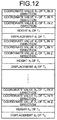
- FIG. 12 is a diagram illustrating data on the height 115 and the displacement 117 of a point 113T i on the trolley wire 102 which have been measured by the height and displacement measurement unit 40 according to the first embodiment.
- the height and displacement measurement unit 40 additionally stores therein information on the measured height 115 and displacement 117 of the point 113T i on the trolley wire 102 in association with the positional information on the point 113T i on the trolley wire 102 obtained from the trolley-wire detection unit 30, that is, in association with the coordinate values of the point 113T i on the trolley wire 102.
- the trolley-wire measurement device 1 performs a process of measuring the point 113 on the trolley wire 102 as is described next with reference to a flowchart.
- FIG. 13 is a flowchart illustrating a trolley-wire measuring process in the trolley-wire measurement device 1 according to the first embodiment.
- the railway measurement unit 20 and the trolley-wire detection unit 30 read the point-group data 11 obtained through plural scans from the storage unit 10 (Step S1).
- a measuring device having generated the point-group data 11 on the basis of three-dimensional measurement, scans a target object as the measuring device is mounted on a vehicle moving on a railway.
- the point-group data 11 obtained through the plural scans is, for example, data on a group of points with a dimension in the depth direction in three dimensions in FIG. 2 that is the traveling direction of a vehicle.
- the railway measurement unit 20 derives the rail plane 106, the railway center line 109, and the railway center plane 110 from the read point-group data 11 (Step S2) .
- FIG. 14 is a flowchart illustrating a process in the railway measurement unit 20 according to the first embodiment.
- the rail detection unit 21 detects the rails 101 from the read point-group data 11 (Step S11).
- the reference setting unit 22 derives the rail plane 106 on the basis of the rails 101 detected by the rail detection unit 21 (Step S12).
- the reference setting unit 22 derives the railway center line 109 on the rail plane 106 (Step S13).
- the reference setting unit 22 derives the railway center plane 110 which is located on the railway center line 109 and orthogonal to the rail plane 106 (Step S14).
- the rail detection unit 21 detects the rails 101 through the process as discussed above.
- the reference setting unit 22 derives the rail plane 106, the railway center line 109, and the railway center plane 110 through the process as described above.
- the trolley-wire detection unit 30 detects the point 113 on the trolley wire 102 from the read point-group data 11 (Step S3).
- the trolley-wire detection unit 30 detects the point 113 on the trolley wire 102 through the process as described above.
- the height and displacement measurement unit 40 obtains the rail plane 106 and the railway center plane 110 from the railway measurement unit 20, and obtains the position of the point 113 on the trolley wire 102 from the trolley-wire detection unit 30.
- the height and displacement measurement unit 40 extracts one of unprocessed points 113 on the trolley wire 102 (Step S4).
- the height and displacement measurement unit 40 measures the distance between the rail plane 106 and the point 113 on the trolley wire 102, as the height 115 of the point 113 on the trolley wire 102 (Step S5).
- the height and displacement measurement unit 40 measures the distance between the railway center plane 110 and the point 113 on the trolley wire 102, as the displacement 117 of the point 113 on the trolley wire 102 (Step S6).
- Step S7 When an unprocessed point on the trolley wire 102 having the height 115 and displacement 117 not yet derived exists (YES at Step S7), the process returns to Step S4 such that the height and displacement measurement unit 40 repeatedly executes the processes from Steps S4 to S6.
- the height and displacement measurement unit 40 ends the measuring process.
- FIG. 15 is a diagram illustrating the height 115 and the displacement 117 of the point 113 on the trolley wire 102 which are measured by the height and displacement measurement unit 40 according to the first embodiment in a case where the rails 101 are curved.
- the height and displacement measurement unit 40 can still measure a distance from the point 113 on the trolley wire 102 to the rail plane 106, as the height 115 of the point 113 on the trolley wire 102, and measure a distance from the point 113 on the trolley wire 102 to the railway center plane 110, as the displacement 117 of the point 113 on the trolley wire 102.
- the trolley-wire measurement device 1 as discussed above measures the height 115 and the displacement 117 of the point 113 on the trolley wire 102 for one railway.
- the trolley-wire measurement device 1 is also capable of measuring the height and the displacement of a point on a trolley wire for the rails of the parallel railway.
- the trolley-wire measurement device 1 is also capable of deriving rails, a rail plane, a railway center line, and a railway center plane for the right railway running in parallel to the left railway as illustrated in FIG.
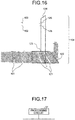
- FIG. 16 is a diagram illustrating a rail plane 122, a railway center line 123, and a railway center plane 124 for the parallel railway, which are derived by the reference setting unit 22 according to the first embodiment.
- FIG. 16 illustrates a positional relation between rails 121, the rail plane 122, the railway center line 123, the railway center plane 124, a trolley wire 125, and a messenger wire 126 for the parallel railway.
- the trolley-wire measurement device 1 when a measuring device having generated the point-group data 11 through three-dimensional measurement is mounted on a vehicle running on the left railway, the trolley-wire measurement device 1 is also capable of deriving the rail plane 122, the railway center line 123, and the railway center plane 124 on the basis of the rails 121 for the right, parallel railway running in parallel to the left railway, thereby measuring the height and the displacement of a point on the trolley wire 125.
- the trolley-wire measurement device 1 is also capable of deriving rails, a rail plane, a railway center line, and a railway center plane for each of the main and side railways, thereby measuring the height and the displacement of a point on a trolley wire on the basis of the rails of each of the main and side railways.
- the rail detection unit 21 detects rails on a railway-by-railway basis.
- the reference setting unit 22 derives a rail plane, a railway center line, and a railway center plane on a railway-by-railway basis, and outputs the first reference and the second reference for each railway, to the height and displacement measurement unit 40.
- the trolley-wire detection unit 30 detects a point on a trolley wire on a railway-by-railway basis.
- the height and displacement measurement unit 40 measures the height and the displacement of the point on the trolley wire on a railway-by-railway basis.
- the trolley-wire measurement device 1 obtains the entire image of the trolley wire 102, and measures the height 115 and the displacement 117 of the point 113 on the trolley wire 102
- the trolley-wire measurement device 1 is not limited to this approach.
- the trolley-wire measurement device 1 may approximate a combination of straight lines from the point group 104 to provide the trolley wire 102, thereby measuring the height 115 and the displacement 117 of the point 113 that is the vertex point of the trolley wire 102 resulting from the approximation.
- Such an approach enables the trolley-wire measurement device 1 to measure the height 115 and the displacement 117 of the point 113 on the trolley wire 102, as with the case of obtaining the entire image of the trolley wire 102 to measure the height 115 and the displacement 117 of the point 113 on the trolley wire 102.
- the volume of the point-group data 11 to be used can be reduced to thereby reduce the amount processed in measuring the height 115 and the displacement 117 of the point 113 on the trolley wire 102.
- the capacity of the storage unit 10 that stores therein the point-group data 11 can be small.
- the trolley-wire measurement device 1 includes a processing circuit to detect the rails 101 from the point-group data 11, derive the rail plane 106, the railway center line 109, and the railway center plane 110, detect the point 113 on the trolley wire 102 from the point-group data 11, and measure the height 115 and the displacement 117 of the point 113 on the trolley wire 102.
- the processing circuit may be dedicated hardware, or a memory and a Central Processing Unit (CPU) that executes a program stored in the memory.
- CPU Central Processing Unit
- FIG. 17 is a diagram illustrating an example in which the processing circuit of the trolley-wire measurement device 1 according to the first embodiment is defined by the dedicated hardware.
- the processing circuit is the dedicated hardware, then for example, a single circuit, a combined circuit, a programmed processor, a parallel-programmed processor, an Application Specific Integrated Circuit (ASIC), a Field Programmable Gate Array (FPGA), or a combination thereof is equivalent to a processing circuit 91 illustrated in FIG. 17 .
- ASIC Application Specific Integrated Circuit
- FPGA Field Programmable Gate Array
- Each of the functions of the railway measurement unit 20, the trolley-wire detection unit 30, and the height and displacement measurement unit 40 may be implemented by the processing circuit 91, or these respective functions may be implemented together by the processing circuit 91.
- FIG. 18 is a diagram illustrating an example in which the processing circuit of the trolley-wire measurement device 1 according to the first embodiment is defined by a CPU and a memory.
- the processing circuit is defined by a CPU 92 and a memory 93
- the functions of the railway measurement unit 20, the trolley-wire detection unit 30, and the height and displacement measurement unit 40 are implemented by software, firmware, or a combination thereof.
- the software or the firmware is described as a program and stored in the memory 93.
- the CPU 92 reads and executes the program stored in the memory 93, thereby implementing the function of each unit.
- the trolley-wire measurement device 1 includes the memory 93 that stores therein programs executed by the processing circuit to perform a step of detecting the rails 101 from the point-group data 11, a step of deriving the rail plane 106, a step of deriving the railway center line 109, a step of deriving the railway center plane 110, a step of detecting the point 113 on the trolley wire 102 from the point-group data 11, and a step of measuring the height 115 and the displacement 117 of the point 113 on the trolley wire 102.
- These programs are also regarded as causing a computer to execute the procedures and methods performed by the railway measurement unit 20, the trolley-wire detection unit 30, and the height and displacement measurement unit 40.
- the CPU 92 can be a processing device, an arithmetic device, a microprocessor, a microcomputer, a processor, or a DSP (Digital Signal Processor).
- a nonvolatile or volatile semiconductor memory such as a RAM (Random Access Memory), a ROM (Read Only Memory), a flash memory, an EPROM (Erasable Programmable ROM), and an EEPROM (Electrically EPROM), a magnetic disk, a flexible disk, an optical disk, a compact disk, a mini disk, or a DVD (Digital Versatile Disc), and the like correspond to the memory 93.
- a memory that implements the storage unit 10 can be used as the memory 93.
- the respective functions of the railway measurement unit 20, the trolley-wire detection unit 30, and the height and displacement measurement unit 40 may be partially implemented by dedicated hardware, and be partially implemented by software or firmware.
- the respective functions of the railway measurement unit 20 and the trolley-wire detection unit 30 can be implemented by the processing circuit 91 that serves as the dedicated hardware, and the CPU 92 can read and execute the program stored in the memory 93 to implement the function of the height and displacement measurement unit 40.
- the processing circuit can implement the respective functions described above by the dedicated hardware, the software, the firmware, or the combination thereof.
- the trolley-wire measurement device 1 detects the rails 101 from the point-group data 11 that is an aggregate of points obtained by measuring a target object three-dimensionally, derives the rail plane 106, the railway center line 109, and the railway center plane 110 on the basis of the detected rails 101, and detects the point 113 on the trolley wire 102 from the point-group data 11 to measure a distance between the rail plane 106 and the point 113 on the trolley wire 102, as the height 115 of the point 113 on the trolley wire 102, and measure a distance between the railway center plane 110 and the point 113 on the trolley wire 102, as the displacement 117 of the point 113 on the trolley wire 102.
- the trolley-wire measurement device 1 can detect the rails 101 and the point 113 on the trolley wire 102 from the same point-group data 11, and can measure the height 115 and the displacement 117 of the point 113 on the trolley wire 102 on the basis of the reference set on the railway, that is, on the basis of the detected rails 101.
- the trolley-wire measurement device 1 can accurately measure the height 115 and the displacement 117 of the point 113 on the trolley wire 102.
- the trolley-wire measurement device 1 detects the rails 101 and the point 113 on the trolley wire 102 from the same point-group data 11 and uses the detected rails 101 and the detected point 113, the trolley-wire measurement device 1 can accurately measure the height 115 and the displacement 117 of the point 113 on the trolley wire 102 even when a vehicle on which the measuring device having generated the point-group data 11 is mounted sways or oscillates during the three-dimensional measurement, or when the railway is curved.
- the trolley-wire measurement device 1 can measure the height and the displacement of a point on a trolley wire for the respective railways in the same manner, and thus can measure the height and the displacement of a point on a trolley wire for each of the parallel railways or each of the main and side railways at the crossover.
- the trolley-wire measurement device 1 can efficiently measure the height and the displacement of a point on a trolley wire on a plurality of railways.
- the reference setting unit 22 derives the railway center plane 110.
- a method of measuring the displacement 117 of the point 113 on the trolley wire 102 without deriving the railway center plane 110 is described.
- a configuration of the trolley-wire measurement device 1 according to the second embodiment is identical to that in the first embodiment (see FIG. 1 ).
- the reference setting unit 22 does not derive the railway center plane 110, and instead, outputs to the height and displacement measurement unit 40 the rail plane 106 as a first reference and the railway center line 109 as a second reference.
- the height and displacement measurement unit 40 measures the height 115 of the point 113 on the trolley wire 102 by using the method identical to that in the first embodiment.
- the height and displacement measurement unit 40 measures a distance between the railway center line 109 and the foot 114 of the perpendicular extending from the point 113 on the trolley wire 102 to the rail plane 106, the measured distance being defined as the displacement 117 of the point 113 on the trolley wire 102.
- the height and displacement measurement unit 40 measures a distance between the foot 114 of the perpendicular extending from the point 113 on the trolley wire 102 to the rail plane 106, and a foot 118 of the perpendicular extending from the point 113 on the trolley wire 102 to the railway center line 109, the measured distance being defined as the displacement 117 of the point 113 on the trolley wire 102.
- FIG. 19 is a diagram illustrating the height 115 and the displacement 117 of the point 113 on the trolley wire 102 which are measured by the height and displacement measurement unit 40 according to the second embodiment. In this manner, the height and displacement measurement unit 40 can measure the displacement 117 of the point 113 on the trolley wire 102 by using only the rail plane 106 and the railway center line 109 which have been obtained from the reference setting unit 22.
- FIG. 20 is a flowchart illustrating a trolley-wire measuring process in the trolley-wire measurement device 1 according to the second embodiment.
- the process at Step S1 is identical to the process in the first embodiment.
- the railway measurement unit 20 derives the rail plane 106 and the railway center line 109 from the read point-group data 11 (Step S2a).
- FIG. 21 is a flowchart illustrating a process in the railway measurement unit 20 according to the second embodiment.
- the flowchart of FIG. 21 does not include the process at Step S14 of the flowchart according to the first embodiment illustrated in FIG. 14 , and includes processes at Steps S11 to S13 of the flowchart of FIG. 21 that are identical to those in the first embodiment.
- a process at Step S3 of FIG. 20 is identical to the process in the first embodiment.
- Processes at Steps S4 and S5 in the height and displacement measurement unit 40 are identical to those in the first embodiment.
- the height and displacement measurement unit 40 measures a distance between the railway center line 109 and the foot 114 of the perpendicular extending from the point 113 on the trolley wire 102 to the rail plane 106, the measured distance being defined as the displacement 117 of the point 113 on the trolley wire 102 (Step S6a).
- a process at Step S7 in the height and displacement measurement unit 40 is identical to the process in the first embodiment.
- the rail detection unit 21 detects rails on a railway-by-railway basis.
- the reference setting unit 22 derives a rail plane and a railway center line on a railway-by-railway basis, and outputs the first reference and the second reference for each railway, to the height and displacement measurement unit 40.
- the trolley-wire detection unit 30 detects a point on a trolley wire on a railway-by-railway basis.
- the height and displacement measurement unit 40 measures the height and the displacement of the point on the trolley wire on a railway-by-railway basis.
- the trolley-wire measurement device 1 detects the rails 101 from the point-group data 11, derives the rail plane 106 and the railway center line 109 on the basis of the detected rails 101, and detects the point 113 on the trolley wire 102 from the point-group data 11 to measure a distance between the rail plane 106 and the point 113 on the trolley wire 102, as the height 115 of the point 113 on the trolley wire 102, and to measure a distance between the railway center line 109 and the foot 114 of the perpendicular extending from the point 113 on the trolley wire 102 to the rail plane 106, as the displacement 117 of the point 113 on the trolley wire 102. Also in this case, effects identical to those of the first embodiment can be obtained.
- the description has been made as to measuring the height 115 and the displacement 117 of the point 113 on the trolley wire 102 by using the point-group data 11 measured in advance.
- a description is made as to measuring the height 115 and the displacement 117 of the point 113 on the trolley wire 102 by using point-group data on a target object that is measured three-dimensionally in real time.
- FIG. 22 is a block diagram illustrating a configuration example of a trolley-wire measurement system 3 including a trolley-wire measurement device 1a and a measuring device 2 according to the third embodiment.
- the trolley-wire measurement system 3 includes the trolley-wire measurement device 1a and the measuring device 2.
- the measuring device 2 which is mounted on a vehicle, three-dimensionally measures target objects including the rails 101, the trolley wire 102, and the like as the measuring device 2 moves with the running vehicle.
- the measuring device 2 includes a three-dimensional measurement unit 81 and a data output unit 82.
- the three-dimensional measurement unit 81 measures a target object three-dimensionally by using the MMS described above, and outputs to the data output unit 82 the point-group data obtained by the three-dimensional measurement.
- the data output unit 82 outputs to the trolley-wire measurement device 1a the obtained point-group data measured three-dimensionally in the three-dimensional measurement unit 81.
- the data output unit 82 can transmit the point-group data to the trolley-wire measurement device 1a through, for example, wireless communication or wire communication. However, the data transmission method is not limited thereto.
- the data output unit 82 may output the point-group data to the trolley-wire measurement device 1a via a recording medium.
- the trolley-wire measurement device 1a is configured by removing the storage unit 10 from the trolley-wire measurement device 1, and adding a data input unit 50 and a measurement-result output unit 60 thereto.
- the data input unit 50 obtains the point-group data from the measuring device 2 that measures a target object three-dimensionally.
- the data input unit 50 can receive the point-group data from the measuring device 2 through, for example, wireless communication or wire communication. However, the data reception method is not limited thereto.
- the data input unit 50 may obtain the point-group data from the measuring device 2 via a recording medium.
- the measurement-result output unit 60 outputs a measurement result of the height 115 and the displacement 117 of the point 113 on the trolley wire 102 which have been measured by the height and displacement measurement unit 40.
- the measurement-result output unit 60 is, for example, a display device that displays the measurement result, a printing device that prints the measurement result, or an interface that outputs the measurement result to a recording medium.
- the measurement-result output unit 60 is not limited thereto.
- the measurement-result output unit 60 may output, for example, information on the coordinate values, the height 115, and the displacement 117 of the point 113T i on the trolley wire 102 illustrated in FIG. 12 as a measurement result.
- the measurement-result output unit 60 may be added to the trolley-wire measurement device 1 illustrated in FIG. 1 . That is, in the first and second embodiments, the measurement-result output unit 60 may output a measurement result of the height 115 and the displacement 117 of the point 113 on the trolley wire 102 which have been measured by the height and displacement measurement unit 40.
- FIG. 23 is a diagram illustrating the rails 101, the trolley wire 102, and the like expressed by point-group data measured three-dimensionally by the measuring device 2 according to the third embodiment.
- the measuring device 2 is defined as being mounted on a vehicle (not illustrated) and measuring a target object three-dimensionally as the measuring device 2 moves in the depth direction in three dimensions in FIG. 23 .
- a section illustrated by a point group 119 obtained through the latest scan is the latest point group measured three-dimensionally by the measuring device 2.
- the rail detection unit 21 can detect the rails 101 from the point group 119 obtained through the latest scan.
- the trolley-wire detection unit 30 can detect the point 113 on the trolley wire 102 from the point group 119 obtained through the latest scan.
- the reference setting unit 22 when the reference setting unit 22 derives the rail plane 106, the railway center line 109, and the railway center plane 110 on the basis of the rails 101 detected by the rail detection unit 21 from the data on the point group 119 obtained through the latest scan, these derived rail plane 106, railway center line 109, and railway center plane 110 may include an error.
- the reference setting unit 22 derives the rail plane 106, the railway center line 109, and the railway center plane 110 on the basis of the rails 101 detected using data on the point group 104 obtained through most recent plural scans, the point group 104 including the point group 119 obtained through the latest scan.
- the reference setting unit 22 stores therein information on the rails 101 detected using the data on the point group 104 obtained through the most recent plural scans.
- the reference setting unit 22 stores therein information on the rail points 107.
- the rail detection unit 21 updates the position of the rails 101 each time the rail detection unit 21 obtains data on the point group 119 detected through the latest scan from the measuring device 2.
- the trolley-wire detection unit 30 updates the point 113 on the trolley wire 102 each time the trolley-wire detection unit 30 obtains data on the point group 119 detected through the latest scan from the measuring device 2.
- the reference setting unit 22 updates the rail plane 106, the railway center line 109, and the railway center plane 110 on the basis of the rails 101 detected from the data on the point group 104 obtained through plural scans including the latest and previous scans.
- the trolley-wire measurement device 1a measures the point 113 on the trolley wire 102 through a process described next with reference to a flowchart.
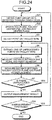
- FIG. 24 is a flowchart illustrating the trolley-wire measuring process in the trolley-wire measurement device 1a according to the third embodiment.
- the railway measurement unit 20 and the trolley-wire detection unit 30 obtain the point-group data detected through a single scan from the measuring device 2 via the data input unit 50 (Step S21).
- the railway measurement unit 20 updates the rail plane 106, the railway center line 109, and the railway center plane 110 by using the obtained point-group data (Step S22).
- FIG. 25 is a flowchart illustrating a process in the railway measurement unit 20 according to the third embodiment.
- the rail detection unit 21 detects and updates the rails 101 from the obtained point-group data (Step S31).
- the reference setting unit 22 derives and updates the rail plane 106 on the basis of the rails 101 detected and updated by the rail detection unit 21 and the rails 101 detected through the multiple previous scans (Step S32).
- the reference setting unit 22 derives and updates the railway center line 109 on the rail plane 106 (Step S33).
- the reference setting unit 22 then derives and updates the railway center plane 110 which is located on the railway center line 109 and orthogonal to the rail plane 106 (Step S34) .
- the trolley-wire detection unit 30 detects the point 113 on the trolley wire 102 from the obtained point-group data (Step S3).
- the trolley-wire detection unit 30 detects the trolley wire 102 and the point 113 on the trolley wire 102 through the process identical to the process in the first embodiment except that the number of pieces of point-group data to be used in Step 3 of the flowchart of FIG. 24 is different from that in the first embodiment.
- the measurement-result output unit 60 When the height and displacement measurement unit 40 outputs a measurement result of the height 115 and the displacement 117 of the point 113 on the trolley wire 102 to the measurement-result output unit 60, the measurement-result output unit 60 outputs the measurement result of the height 115 and the displacement 117 of the point 113 on the trolley wire 102 on a display or the like (Step S23). As a result, personnel in charge of maintenance or the like can check the measurement result of the height 115 and the displacement 117 of the point 113 on the trolley wire 102 in real time.
- Step S24 When the trolley-wire measurement device 1a continues the measurement of the trolley wire 102 (YES at Step S24), the process returns to Step S21 such that the trolley-wire measurement device 1a repeatedly executes the processes described above.
- the trolley-wire measurement device 1a terminates the measurement of the trolley wire 102 (NO at Step S24), the trolley-wire measurement device 1a ends the process.
- the data input unit 50 is configured by an interface circuit or the like that receives data input from a recording medium, a wire communication device, and a wireless communication device.
- the measurement-result output unit 60 is configured by an interface circuit or the like that outputs data to a recording medium, a printer, and a monitor.
- Individual configurations of the railway measurement unit 20, the trolley-wire detection unit 30, and the height and displacement measurement unit 40 are identical to those in the first embodiment, respectively.
- the trolley-wire measurement device 1a obtains point-group data from the measuring device 2 in real time, detects the rails 101 by using the obtained point-group data, derives the rail plane 106, the railway center line 109, and the railway center plane 110, detects the point 113 on the trolley wire 102 from the point-group data, measures the height 115 and the displacement 117 of the point 113 on the trolley wire 102, and outputs the measurement result of the height 115 and the displacement 117 of the point 113 on the trolley wire 102.
- the trolley-wire measurement device 1a can achieve the identical effects to those obtained in the first embodiment, and further can output the measurement result of the height 115 and the displacement 117 of the point 113 on the trolley wire 102 to the personnel in charge of maintenance or the like in real time.
- FIG. 26 is a block diagram illustrating a configuration example of a trolley-wire measurement device 1b according to the fourth embodiment.
- the trolley-wire measurement device 1b is configured by adding a support-point detection unit 70 to the configuration of the trolley-wire measurement device 1.
- the support-point detection unit 70 detects from the point-group data 11 stored in the storage unit 10 a point on the overhead wire, a point on the hanger wire, and a point on the fitting, the messenger wire 103, the hanger wire, and the fitting being arranged to support the trolley wire 102.
- the support-point detection unit 70 can detect, for example, the point above the trolley wire 102 as the messenger wire 103, and the point between the trolley wire 102 and the messenger wire 103 as the hanger wire, as with the process of detecting the trolley wire 102 in the trolley-wire detection unit 30.
- the support-point detection unit 70 can further detect the fitting by, for example, performing matching between the detected points and a template expressing the shape of the fitting, as with the manner of detecting the rails 101 in the rail detection unit 21.
- the process of detecting the messenger wire 103, the hanger wire, and the fitting in the support-point detection unit 70 described above is merely an example, and the process is not limited thereto.
- the height and displacement measurement unit 40 uses the respective positions of the messenger wire 103, the hanger wire, and the fitting which have been detected by the support-point detection unit 70.
- the measurement result of the height 115 and the displacement 117 of the trolley wire 102 can incorporate therein the information regarding whether the point 113 on the trolley wire 102 is at a section where there is the fitting, or at a section where there is the hanger wire.
- the information useful for the personnel in charge of the maintenance personnel can be provided.
- FIG. 27 is a flowchart illustrating a trolley-wire measuring process in the trolley-wire measurement device 1b according to the fourth embodiment.
- a process of detecting the messenger wire 103, the hanger wire, and the fitting in the support-point detection unit 70 is added as Step S41 between Step S3 and Step S4, Step S41 coming before Step S4 to which the process returns when the determination at Step S7 is YES.
- Other processes are identical to those in the first embodiment.
- the support-point detection unit 70 is implemented by a processing circuit similar to the processing circuit of the trolley-wire detection unit 30 and the like, that is, implemented by dedicated hardware, software, firmware, or a combination thereof.
- the trolley-wire measurement device 1b further detects the messenger wire 103, a hanger wire, a fitting, and the like that support the trolley wire 102, in addition to performing the processes in the first embodiment. Accordingly, information on the messenger wire 103, the hanger wire, and the fitting can be added to the measurement result of the height 115 and the displacement 117 of the point 113 on the trolley wire 102, thereby providing the information useful for the personnel in charge of maintenance.
- trolley-wire measurement device 1, 1a, 1b trolley-wire measurement device, 2 measuring device, 3 trolley-wire measurement system, 10 storage unit, 11 point-group data, 20 railway measurement unit, 21 rail detection unit, 22 reference setting unit, 30 trolley-wire detection unit, 40 height and displacement measurement unit, 50 data input unit, 60 measurement-result output unit, 70 support-point detection unit, 81 three-dimensional measurement unit, 82 data output unit.
Landscapes
- Physics & Mathematics (AREA)
- General Physics & Mathematics (AREA)
- Engineering & Computer Science (AREA)
- Mechanical Engineering (AREA)
- Manufacturing & Machinery (AREA)
- Length Measuring Devices With Unspecified Measuring Means (AREA)
- Length Measuring Devices By Optical Means (AREA)
Abstract
Description
- The present invention relates to a trolley-wire measurement device and a trolley-wire measurement method for measuring the position of a trolley wire.
- There has conventionally been a device that measures the position of a trolley wire for supplying the power to a train.
Patent Literature 1 below discloses a technique for determining that relatively low points of measured points within a set range are a trolley wire candidate to calculate coordinate values of the trolley wire on the basis of the installation conditions of the trolley wire and the speed of a vehicle with a measurement device mounted thereon. - Patent Literature 1: Japanese Patent Application No.
2010-243416 - For the conventional technique described above, unfortunately, the position of a trolley wire is measured with reference to the measurement device mounted on a vehicle. Such a measurement poses a problem of failure to accurately measure the position of a trolley wire relative to the reference if the vehicle sways.
- The present invention has been achieved to solve the above problems, and an object of the present invention is to provide a trolley-wire measurement device that is capable of measuring a height and a displacement of a trolley wire relative to a reference set on a railway.
- In order to solve the above problems and achieve the object, the present invention provides a trolley-wire measurement device comprising: a rail detection unit to detect rails from point-group data that is an aggregate of points obtained by measuring a target object three-dimensionally, the rails defining a railway on which a train runs; a reference setting unit to set a reference for measuring a height and a displacement of a point on a trolley wire on a basis of the rails detected; a trolley-wire detection unit to detect the point on the trolley wire from the point-group data; and a height and displacement measurement unit to measure the height and the displacement of the point on the trolley wire by using the reference.
- The present invention provides an effect of measuring the height and the displacement of the trolley wire relative to the reference set on the railway.
-
-
FIG. 1 is a block diagram illustrating a configuration example of a trolley-wire measurement device according to a first embodiment. -
FIG. 2 is a diagram illustrating an example of a three-dimensionally measured target object that is expressed by point-group data stored in a storage unit according to the first embodiment. -
FIG. 3 is a diagram illustrating a configuration example of the point-group data stored in the storage unit according to the first embodiment. -
FIG. 4 is a conceptual diagram illustrating a process of detecting a rail in a rail detection unit according to the first embodiment. -
FIG. 5 is a conceptual diagram illustrating a process of deriving a rail plane in a reference setting unit according to the first embodiment. -
FIG. 6 is a conceptual diagram illustrating a process of deriving a railway center line in the reference setting unit according to the first embodiment. -
FIG. 7 is a diagram illustrating an example of data on rail points held in the rail detection unit according to the first embodiment. -
FIG. 8 is a diagram illustrating how a railway center plane derived by the reference setting unit relates to a rail plane and the railway center line according to the first embodiment. -
FIG. 9 is a diagram illustrating an example of an extraction area of point-group data to be extracted from the storage unit in a trolley-wire detection unit according to the first embodiment. -
FIG. 10 is a diagram illustrating a height and a displacement of a point on a trolley wire which are measured by a height and displacement measurement unit according to the first embodiment. -
FIG. 11 is a diagram illustrating a positional relation between a train and a height and a displacement of a point on the trolley wire which have been measured by the height and displacement measurement unit according to the first embodiment. -
FIG. 12 is a diagram illustrating data on a height and a displacement of a point on the trolley wire which have been measured by the height and displacement measurement unit according to the first embodiment. -
FIG. 13 is a flowchart illustrating a trolley-wire measuring process in the trolley-wire measurement device according to the first embodiment. -
FIG. 14 is a flowchart illustrating a process in a railway measurement unit according to the first embodiment. -
FIG. 15 is a diagram illustrating a height and a displacement of a point on the trolley wire which are measured by the height and displacement measurement unit according to the first embodiment in a case where rails are curved. -
FIG. 16 is a diagram illustrating a rail plane, a railway center line, and a railway center plane of a parallel railway, which are derived by the reference setting unit according to the first embodiment. -
FIG. 17 is a diagram illustrating an example in which a processing circuit of the trolley-wire measurement device according to the first embodiment is defined by dedicated hardware. -
FIG. 18 is a diagram illustrating an example in which the processing circuit of the trolley-wire measurement device according to the first embodiment is defined by a CPU and a memory. -
FIG. 19 is a diagram illustrating a height and a displacement of a point on a trolley wire which are measured by a height and displacement measurement unit according to a second embodiment. -
FIG. 20 is a flowchart illustrating a trolley-wire measuring process in a trolley-wire measurement device according to the second embodiment. -
FIG. 21 is a flowchart illustrating a process in a railway measurement unit according to the second embodiment. -
FIG. 22 is a block diagram illustrating a configuration example of a trolley-wire measurement system including a trolley-wire measurement device and a measuring device according to a third embodiment. -
FIG. 23 is a diagram illustrating rails, a trolley wire, and the like expressed by point-group data measured three-dimensionally by the measuring device according to the third embodiment. -
FIG. 24 is a flowchart illustrating a trolley-wire measuring process in the trolley-wire measurement device according to the third embodiment. -
FIG. 25 is a flowchart illustrating a process in a railway measurement unit according to the third embodiment. -
FIG. 26 is a block diagram illustrating a configuration example of a trolley-wire measurement device according to a fourth embodiment. -
FIG. 27 is a flowchart illustrating a trolley-wire measuring process in the trolley-wire measurement device according to the fourth embodiment. - A trolley-wire measurement device and a trolley-wire measurement method according to embodiments of the present invention will be described in detail below with reference to the accompanying drawings. The present invention is not limited to the embodiments.
-
FIG. 1 is a block diagram illustrating a configuration example of a trolley-wire measurement device 1 according to a first embodiment of the present invention. The trolley-wire measurement device 1 measures the position of a trolley wire relative to a reference that is set on the basis of the position of rails that define a railway on which a train runs. Specifically, the trolley-wire measurement device 1 measures a height and a displacement of a trolley wire. The trolley-wire measurement device 1 includes astorage unit 10, arailway measurement unit 20, a trolley-wire detection unit 30, and a height anddisplacement measurement unit 40. - The
storage unit 10 stores point-group data 11 therein. The point-group data 11, which is an aggregate of points having three-dimensional coordinate values, is a result of a three-dimensional measurement of a target object such as a trolley wire, a messenger wire, and a rail. The point-group data 11 refers to data expressed in terms of coordinate values of the points measured three-dimensionally by a measuring device using a laser scanner, a camera, a GPS antenna, and the like. The point-group data 11 is data on points measured three-dimensionally by the measuring device such as a Mobile Mapping System (MMS). However, the point-group data 11 is not limited thereto.FIG. 2 is a diagram illustrating an example of a three-dimensionally measured target object that is expressed by the point-group data 11 stored in thestorage unit 10 according to the first embodiment. InFIG. 2 , the scope of the three-dimensionally measured target object expressed by the point-group data 11 is defined as includingrails 101 laid on the ground, atrolley wire 102 hanging in the air, amessenger wire 103 suspending thetrolley wire 102, and the like. One point Pi of apoint group 104 of the three-dimensionally measured target object can be expressed as Pi (xi, yi, zi) by using three-axis coordinate values in the x-axis direction, the y-axis direction, and the z-axis direction.FIG. 3 is a diagram illustrating a configuration example of the point-group data 11 stored in thestorage unit 10 according to the first embodiment. Thestorage unit 10 stores therein the point-group data 11 that is defined by the data on three-axis coordinate values of points P1 to PK including the aforementioned point Pi in the x-axis direction, the y-axis direction, and the z-axis direction. The x-axis direction, the y-axis direction, and the z-axis direction can be defined, for example, using a plane rectangular coordinate system such that the xy-axis is in the horizontal plane and the z-axis is oriented in the height direction. Alternatively, a coordinate system may be employed which has an origin at any point and defines, for example, the eastward direction as the x-axis direction, the northward direction as the y-axis direction, and the vertically upward direction as the z-axis direction. The unit indicating the data on the coordinate values of each point can be, but not limited to, meters (m) or the like. - The
railway measurement unit 20 includes arail detection unit 21 and areference setting unit 22. - The
rail detection unit 21 detects therail 101 from the point-group data 11 stored in thestorage unit 10. For example, therail detection unit 21 extracts from the point-group data 11 thepoint group 104 defined by a plurality of points, and then detects therail 101 by performing matching between the shape expressed by the extractedpoint group 104 and atemplate 105 that is an aggregate of points taking the shape of therail 101.FIG. 4 is a conceptual diagram illustrating a process of detecting therail 101 in therail detection unit 21 according to the first embodiment. As illustrated inFIG. 4 , therail detection unit 21 detects that there is therail 101 at the position of thepoint group 104 that matches the shape of thetemplate 105. - On the basis of the
rails 101 detected by therail detection unit 21, thereference setting unit 22 sets a reference for measurement of the height and the displacement of the point on thetrolley wire 102. Specifically, on the basis of therails 101 detected by therail detection unit 21, thereference setting unit 22 derives a rail plane which is a plane connecting respective top surfaces of the detected, two, left andright rails 101, that is, thereference setting unit 22 derives the rail plane that is a plane including the surfaces which a train contacts.FIG. 5 is a conceptual diagram illustrating a process of deriving arail plane 106 in thereference setting unit 22 according to the first embodiment. As illustrated inFIG. 5 , thereference setting unit 22 sets therail plane 106 that is the plane connecting the respective top surfaces of the two, left andright rails 101. In practice, thereference setting unit 22 may compute to thereby derive therail surface 106 from the point-group data 11 illustrated inFIG. 3 without drawing therails 101 as illustrated inFIG. 5 . - The
reference setting unit 22 derives from the rail plane 106 a railway center line positioned at the center between the two left and right side rails 101.FIG. 6 is a conceptual diagram illustrating a process of deriving arailway center line 109 in thereference setting unit 22 according to the first embodiment. For example, thereference setting unit 22 sets rail points 107 at positions on the inner sides of the top portions of the two, left and right ones of therails 101 detected by therail detection unit 21. Thereference setting unit 22 derives arail line 108 connecting the rail points 107 of each of the left andright rails 101 by, for example, least squares approximation of the rail points 107. Thereference setting unit 22 then derives therailway center line 109 that is a line positioned at the center between the respective derivedrail lines 108 of the left andright rails 101. Therailway center line 109 is equally distant from each of therails 101. The positions of the rail points 107 are not limited to the inner sides of the top portions of the two, left andright rails 101, but may be the outer sides of the top portions of the two, left andright rails 101. - In
FIG. 6 , the rail points 107 indicate particular positions on therail 101 detected by therail detection unit 21. In this example, the rail points 107 indicate the positions on the inner sides of the top portions of the two left andright rails 101. The detection process in therail detection unit 21 provides the coordinate values of the rail points 107 for the corrected location at which therail 101 should be disposed relative to the live measured point-group data stored in the point-group data 11.FIG. 7 is a diagram illustrating an example of the data on the rail points 107 held in therail detection unit 21 according to the first embodiment. Therail detection unit 21 holds therein the data on the rail points 107 illustrated inFIG. 7 . Thereference setting unit 22 uses the data on the rail points 107 illustrated inFIG. 7 . As illustrated inFIGS. 6 and 7 , therail detection unit 21 detects the tworails 101 per railway that are the left andright rails 101 in this example, and holds the data onrail points 107Li of the left-side rail 101 and the data on rail points 107Ri of the right-side rail 101. - Further, the
reference setting unit 22 derives a railway center plane orthogonal to therail plane 106 on therailway center line 109.FIG. 8 is a diagram illustrating how arailway center plane 110 derived by thereference setting unit 22 relates to therail plane 106 and therailway center line 109 according to the first embodiment. InFIG. 8 , therail plane 106, therailway center line 109, and therailway center plane 110 are added to the illustrations inFIG. 2 . Thereference setting unit 22 outputs the derivedrail plane 106 and the derivedrailway center plane 110 as a first reference and a second reference, respectively, to the height anddisplacement measurement unit 40. - The trolley-
wire detection unit 30 detects points on thetrolley wire 102 from the point-group data 11 stored in thestorage unit 10. The trolley-wire detection unit 30 is capable of performing a process of detecting points on thetrolley wire 102 on all of the pieces of point-group data 11 stored in thestorage unit 10. Unfortunately, such a detection process for all of the pieces of point-group data increases the processing amount for detecting the points on thetrolley wire 102. It is thus desirable for the trolley-wire detection unit 30 to limit the area of thepoint group 104 that is to be extracted from the point-group data 11. For example, the trolley-wire detection unit 30 defines a specified range at a certain height or greater as an area of thepoint group 104 that is to be extracted. Alternatively, where the measurement of thetrolley wire 102 has been previously performed, the lateral extraction area may be limited using information on the track of a vehicle having the measuring device mounted thereon at the time of the previous measurement, and information on the rail position. - In general, the position of the
trolley wire 102 is defined such that the height of the trolley wire from therail plane 106 falls within a specified range, and that the displacement of the trolley wire, which is a distance from therailway center plane 110, falls within a specified range. Although not illustrated inFIG. 1 , thus, the trolley-wire detection unit 30 obtains information on therail plane 106 and therailway center plane 110 from thereference setting unit 22, and then limits the area of thepoint group 104 that is to be extracted from the point-group data 11, to a range slightly greater than the range of the height and displacement specified as the position of thetrolley wire 102.FIG. 9 is a diagram illustrating an example of an extraction area of the point-group data 11 to be extracted from thestorage unit 10 in the trolley-wire detection unit 30 according to the first embodiment.FIG. 9 illustrates a positional relation between anextraction area 112, and therails 101, thetrolley wire 102, therail plane 106, therailway center plane 110, atrain 111, apoint 113 on thetrolley wire 102, and the like. The trolley-wire detection unit 30, which extracts from thestorage unit 10 the point-group data 11 within thelimited extraction area 112, can reduce the processing amount for detecting thepoint 113 on thetrolley wire 102. - When a plurality of target objects is extracted from the area of the extracted
point group 104 and the extracted target objects are arranged in the vertical direction, the trolley-wire detection unit 30 detects the lower one of the target objects as thepoint 113 on thetrolley wire 102 because, in view of the overhead wire structure, the lower target object is regarded as thetrolley wire 102 and the upper target object is regarded as themessenger wire 103 suspending thetrolley wire 102. The trolley-wire detection unit 30 outputs the position of the detectedpoint 113 on thetrolley wire 102, that is, outputs information on the coordinate values of thepoint 113 on thetrolley wire 102, to the height anddisplacement measurement unit 40. - The height and
displacement measurement unit 40 uses the position of thepoint 113 on thetrolley wire 102 obtained from the trolley-wire detection unit 30, therail plane 106 that is a first reference, and therailway center plane 110 that is a second reference obtained from thereference setting unit 22, thereby measuring the height of thepoint 113 on thetrolley wire 102 from therail plane 106, and the displacement of thepoint 113 on thetrolley wire 102 from therailway center plane 110.FIG. 10 is a diagram illustrating aheight 115 and adisplacement 117 of thepoint 113 on thetrolley wire 102 which are measured by the height anddisplacement measurement unit 40 according to the first embodiment. The height anddisplacement measurement unit 40 defines theheight 115 of thepoint 113 on thetrolley wire 102 as a length from thepoint 113 on thetrolley wire 102 to afoot 114 of the perpendicular extending to therail plane 106. That is, the height anddisplacement measurement unit 40 defines theheight 115 as a distance between therail plane 106 and thepoint 113 on thetrolley wire 102. Further, the height anddisplacement measurement unit 40 defines thedisplacement 117 of thepoint 113 on thetrolley wire 102 as a length from thepoint 113 on thetrolley wire 102 to afoot 116 of the perpendicular extending to therailway center plane 110. That is, the height anddisplacement measurement unit 40 defines thedisplacement 117 as a distance between therailway center plane 110 and thepoint 113 on thetrolley wire 102. -
FIG. 11 is a diagram illustrating a positional relation between thetrain 111 and theheight 115 and thedisplacement 117 of thepoint 113 on thetrolley wire 102 which have been measured by the height anddisplacement measurement unit 40 according to the first embodiment. By virtue of theheight 115 and thedisplacement 117 of thepoint 113 on thetrolley wire 102 which have been measured by the height anddisplacement measurement unit 40, personnel in charge of the railway facility maintenance can determine whether the position of thepoint 113 on thetrolley wire 102 falls within a range specified by a railway company or the like, that is, whether the position of thepoint 113 on thetrolley wire 102 agrees with the specifiedheight 115 and the specifieddisplacement 117.FIG. 12 is a diagram illustrating data on theheight 115 and thedisplacement 117 of a point 113Ti on thetrolley wire 102 which have been measured by the height anddisplacement measurement unit 40 according to the first embodiment. The height anddisplacement measurement unit 40 additionally stores therein information on the measuredheight 115 anddisplacement 117 of the point 113Ti on thetrolley wire 102 in association with the positional information on the point 113Ti on thetrolley wire 102 obtained from the trolley-wire detection unit 30, that is, in association with the coordinate values of the point 113Ti on thetrolley wire 102. - The trolley-
wire measurement device 1 performs a process of measuring thepoint 113 on thetrolley wire 102 as is described next with reference to a flowchart.FIG. 13 is a flowchart illustrating a trolley-wire measuring process in the trolley-wire measurement device 1 according to the first embodiment. In the trolley-wire measurement device 1, first, therailway measurement unit 20 and the trolley-wire detection unit 30 read the point-group data 11 obtained through plural scans from the storage unit 10 (Step S1). In general, a measuring device, having generated the point-group data 11 on the basis of three-dimensional measurement, scans a target object as the measuring device is mounted on a vehicle moving on a railway. The point-group data 11 obtained through the plural scans is, for example, data on a group of points with a dimension in the depth direction in three dimensions inFIG. 2 that is the traveling direction of a vehicle. - The
railway measurement unit 20 derives therail plane 106, therailway center line 109, and therailway center plane 110 from the read point-group data 11 (Step S2) . -
FIG. 14 is a flowchart illustrating a process in therailway measurement unit 20 according to the first embodiment. In therailway measurement unit 20, first, therail detection unit 21 detects therails 101 from the read point-group data 11 (Step S11). Next, thereference setting unit 22 derives therail plane 106 on the basis of therails 101 detected by the rail detection unit 21 (Step S12). Then, thereference setting unit 22 derives therailway center line 109 on the rail plane 106 (Step S13). Finally, thereference setting unit 22 derives therailway center plane 110 which is located on therailway center line 109 and orthogonal to the rail plane 106 (Step S14). Therail detection unit 21 detects therails 101 through the process as discussed above. Thereference setting unit 22 derives therail plane 106, therailway center line 109, and therailway center plane 110 through the process as described above. - Referring back to the flowchart in
FIG. 13 , the trolley-wire detection unit 30 detects thepoint 113 on thetrolley wire 102 from the read point-group data 11 (Step S3). The trolley-wire detection unit 30 detects thepoint 113 on thetrolley wire 102 through the process as described above. - The height and
displacement measurement unit 40 obtains therail plane 106 and therailway center plane 110 from therailway measurement unit 20, and obtains the position of thepoint 113 on thetrolley wire 102 from the trolley-wire detection unit 30. The height anddisplacement measurement unit 40 extracts one ofunprocessed points 113 on the trolley wire 102 (Step S4). - The height and
displacement measurement unit 40 measures the distance between therail plane 106 and thepoint 113 on thetrolley wire 102, as theheight 115 of thepoint 113 on the trolley wire 102 (Step S5). - The height and
displacement measurement unit 40 measures the distance between therailway center plane 110 and thepoint 113 on thetrolley wire 102, as thedisplacement 117 of thepoint 113 on the trolley wire 102 (Step S6). - When an unprocessed point on the
trolley wire 102 having theheight 115 anddisplacement 117 not yet derived exists (YES at Step S7), the process returns to Step S4 such that the height anddisplacement measurement unit 40 repeatedly executes the processes from Steps S4 to S6. - When an unprocessed point on the
trolley wire 102 havingheight 115 anddisplacement 117 not yet derived does not exist (NO at Step S7), the height anddisplacement measurement unit 40 ends the measuring process. - Although the present embodiment has been described by way of example with reference to the
rails 101 that are straight as illustrated inFIG. 10 and other diagrams, the present invention is also applicable to therails 101 that are curved.FIG. 15 is a diagram illustrating theheight 115 and thedisplacement 117 of thepoint 113 on thetrolley wire 102 which are measured by the height anddisplacement measurement unit 40 according to the first embodiment in a case where therails 101 are curved. Even in the case where therails 101 are curved, the height anddisplacement measurement unit 40 can still measure a distance from thepoint 113 on thetrolley wire 102 to therail plane 106, as theheight 115 of thepoint 113 on thetrolley wire 102, and measure a distance from thepoint 113 on thetrolley wire 102 to therailway center plane 110, as thedisplacement 117 of thepoint 113 on thetrolley wire 102. The same applies to other embodiments to be described later. - The trolley-
wire measurement device 1 as discussed above measures theheight 115 and thedisplacement 117 of thepoint 113 on thetrolley wire 102 for one railway. When there is another railway running in parallel to the one railway, the trolley-wire measurement device 1 is also capable of measuring the height and the displacement of a point on a trolley wire for the rails of the parallel railway. When the point-group data 11 stored in thestorage unit 10 includes point-group data regarding a plurality of railways, as illustrated inFIG. 8 , the trolley-wire measurement device 1 is also capable of deriving rails, a rail plane, a railway center line, and a railway center plane for the right railway running in parallel to the left railway as illustrated inFIG. 8 , as with the left railway, thereby measuring the height and the displacement of a point on a trolley wire for the parallel railway.FIG. 16 is a diagram illustrating arail plane 122, arailway center line 123, and arailway center plane 124 for the parallel railway, which are derived by thereference setting unit 22 according to the first embodiment.FIG. 16 illustrates a positional relation betweenrails 121, therail plane 122, therailway center line 123, therailway center plane 124, atrolley wire 125, and amessenger wire 126 for the parallel railway. For example, inFIG. 8 andFIG. 16 , when a measuring device having generated the point-group data 11 through three-dimensional measurement is mounted on a vehicle running on the left railway, the trolley-wire measurement device 1 is also capable of deriving therail plane 122, therailway center line 123, and therailway center plane 124 on the basis of therails 121 for the right, parallel railway running in parallel to the left railway, thereby measuring the height and the displacement of a point on thetrolley wire 125. - Further, at a crossover section where a plurality of railways branch off or join together, the trolley-
wire measurement device 1 is also capable of deriving rails, a rail plane, a railway center line, and a railway center plane for each of the main and side railways, thereby measuring the height and the displacement of a point on a trolley wire on the basis of the rails of each of the main and side railways. - When the point-
group data 11 includes points regarding a plurality of railways, therail detection unit 21 detects rails on a railway-by-railway basis. Thereference setting unit 22 derives a rail plane, a railway center line, and a railway center plane on a railway-by-railway basis, and outputs the first reference and the second reference for each railway, to the height anddisplacement measurement unit 40. The trolley-wire detection unit 30 detects a point on a trolley wire on a railway-by-railway basis. The height anddisplacement measurement unit 40 measures the height and the displacement of the point on the trolley wire on a railway-by-railway basis. - Although the trolley-
wire measurement device 1 discussed above obtains the entire image of thetrolley wire 102, and measures theheight 115 and thedisplacement 117 of thepoint 113 on thetrolley wire 102, the trolley-wire measurement device 1 is not limited to this approach. For example, the trolley-wire measurement device 1 may approximate a combination of straight lines from thepoint group 104 to provide thetrolley wire 102, thereby measuring theheight 115 and thedisplacement 117 of thepoint 113 that is the vertex point of thetrolley wire 102 resulting from the approximation. Such an approach enables the trolley-wire measurement device 1 to measure theheight 115 and thedisplacement 117 of thepoint 113 on thetrolley wire 102, as with the case of obtaining the entire image of thetrolley wire 102 to measure theheight 115 and thedisplacement 117 of thepoint 113 on thetrolley wire 102. For the trolley-wire measurement device 1, the volume of the point-group data 11 to be used can be reduced to thereby reduce the amount processed in measuring theheight 115 and thedisplacement 117 of thepoint 113 on thetrolley wire 102. As a result, the capacity of thestorage unit 10 that stores therein the point-group data 11 can be small. - Next, a hardware configuration of the trolley-
wire measurement device 1 is described. In the trolley-wire measurement device 1, thestorage unit 10 is implemented by a memory. Each of the functions of therailway measurement unit 20 defined by therail detection unit 21 and thereference setting unit 22, the trolley-wire detection unit 30, and the height anddisplacement measurement unit 40 is implemented by a processing circuit. That is, the trolley-wire measurement device 1 includes a processing circuit to detect therails 101 from the point-group data 11, derive therail plane 106, therailway center line 109, and therailway center plane 110, detect thepoint 113 on thetrolley wire 102 from the point-group data 11, and measure theheight 115 and thedisplacement 117 of thepoint 113 on thetrolley wire 102. The processing circuit may be dedicated hardware, or a memory and a Central Processing Unit (CPU) that executes a program stored in the memory. -
FIG. 17 is a diagram illustrating an example in which the processing circuit of the trolley-wire measurement device 1 according to the first embodiment is defined by the dedicated hardware. When the processing circuit is the dedicated hardware, then for example, a single circuit, a combined circuit, a programmed processor, a parallel-programmed processor, an Application Specific Integrated Circuit (ASIC), a Field Programmable Gate Array (FPGA), or a combination thereof is equivalent to aprocessing circuit 91 illustrated inFIG. 17 . Each of the functions of therailway measurement unit 20, the trolley-wire detection unit 30, and the height anddisplacement measurement unit 40 may be implemented by theprocessing circuit 91, or these respective functions may be implemented together by theprocessing circuit 91. -
FIG. 18 is a diagram illustrating an example in which the processing circuit of the trolley-wire measurement device 1 according to the first embodiment is defined by a CPU and a memory. In a case where the processing circuit is defined by aCPU 92 and amemory 93, the functions of therailway measurement unit 20, the trolley-wire detection unit 30, and the height anddisplacement measurement unit 40 are implemented by software, firmware, or a combination thereof. The software or the firmware is described as a program and stored in thememory 93. In the processing circuit, theCPU 92 reads and executes the program stored in thememory 93, thereby implementing the function of each unit. That is, the trolley-wire measurement device 1 includes thememory 93 that stores therein programs executed by the processing circuit to perform a step of detecting therails 101 from the point-group data 11, a step of deriving therail plane 106, a step of deriving therailway center line 109, a step of deriving therailway center plane 110, a step of detecting thepoint 113 on thetrolley wire 102 from the point-group data 11, and a step of measuring theheight 115 and thedisplacement 117 of thepoint 113 on thetrolley wire 102. These programs are also regarded as causing a computer to execute the procedures and methods performed by therailway measurement unit 20, the trolley-wire detection unit 30, and the height anddisplacement measurement unit 40. TheCPU 92 can be a processing device, an arithmetic device, a microprocessor, a microcomputer, a processor, or a DSP (Digital Signal Processor). A nonvolatile or volatile semiconductor memory such as a RAM (Random Access Memory), a ROM (Read Only Memory), a flash memory, an EPROM (Erasable Programmable ROM), and an EEPROM (Electrically EPROM), a magnetic disk, a flexible disk, an optical disk,
a compact disk, a mini disk, or a DVD (Digital Versatile Disc), and the like correspond to thememory 93. A memory that implements thestorage unit 10 can be used as thememory 93. - The respective functions of the
railway measurement unit 20, the trolley-wire detection unit 30, and the height anddisplacement measurement unit 40 may be partially implemented by dedicated hardware, and be partially implemented by software or firmware. For example, the respective functions of therailway measurement unit 20 and the trolley-wire detection unit 30 can be implemented by theprocessing circuit 91 that serves as the dedicated hardware, and theCPU 92 can read and execute the program stored in thememory 93 to implement the function of the height anddisplacement measurement unit 40. - In this manner, the processing circuit can implement the respective functions described above by the dedicated hardware, the software, the firmware, or the combination thereof.
- As described above, according to the present embodiment, the trolley-
wire measurement device 1 detects therails 101 from the point-group data 11 that is an aggregate of points obtained by measuring a target object three-dimensionally, derives therail plane 106, therailway center line 109, and therailway center plane 110 on the basis of the detectedrails 101, and detects thepoint 113 on thetrolley wire 102 from the point-group data 11 to measure a distance between therail plane 106 and thepoint 113 on thetrolley wire 102, as theheight 115 of thepoint 113 on thetrolley wire 102, and measure a distance between therailway center plane 110 and thepoint 113 on thetrolley wire 102, as thedisplacement 117 of thepoint 113 on thetrolley wire 102. That is, the trolley-wire measurement device 1 can detect therails 101 and thepoint 113 on thetrolley wire 102 from the same point-group data 11, and can measure theheight 115 and thedisplacement 117 of thepoint 113 on thetrolley wire 102 on the basis of the reference set on the railway, that is, on the basis of the detected rails 101. Thus, since the relative positions of therails 101 and thepoint 113 on thetrolley wire 102 are accurate, the trolley-wire measurement device 1 can accurately measure theheight 115 and thedisplacement 117 of thepoint 113 on thetrolley wire 102. - Further, since the trolley-
wire measurement device 1 detects therails 101 and thepoint 113 on thetrolley wire 102 from the same point-group data 11 and uses the detectedrails 101 and the detectedpoint 113, the trolley-wire measurement device 1 can accurately measure theheight 115 and thedisplacement 117 of thepoint 113 on thetrolley wire 102 even when a vehicle on which the measuring device having generated the point-group data 11 is mounted sways or oscillates during the three-dimensional measurement, or when the railway is curved. - Furthermore, when the point-
group data 11 includes the point-group data regarding a plurality of railways, the trolley-wire measurement device 1 can measure the height and the displacement of a point on a trolley wire for the respective railways in the same manner, and thus can measure the height and the displacement of a point on a trolley wire for each of the parallel railways or each of the main and side railways at the crossover. The trolley-wire measurement device 1 can efficiently measure the height and the displacement of a point on a trolley wire on a plurality of railways. - In the first embodiment, the
reference setting unit 22 derives therailway center plane 110. In a second embodiment, a method of measuring thedisplacement 117 of thepoint 113 on thetrolley wire 102 without deriving therailway center plane 110 is described. - A configuration of the trolley-
wire measurement device 1 according to the second embodiment is identical to that in the first embodiment (seeFIG. 1 ). In the present embodiment, thereference setting unit 22 does not derive therailway center plane 110, and instead, outputs to the height anddisplacement measurement unit 40 therail plane 106 as a first reference and therailway center line 109 as a second reference. - The height and
displacement measurement unit 40 measures theheight 115 of thepoint 113 on thetrolley wire 102 by using the method identical to that in the first embodiment. In the present embodiment, the height anddisplacement measurement unit 40 measures a distance between therailway center line 109 and thefoot 114 of the perpendicular extending from thepoint 113 on thetrolley wire 102 to therail plane 106, the measured distance being defined as thedisplacement 117 of thepoint 113 on thetrolley wire 102. For example, the height anddisplacement measurement unit 40 measures a distance between thefoot 114 of the perpendicular extending from thepoint 113 on thetrolley wire 102 to therail plane 106, and afoot 118 of the perpendicular extending from thepoint 113 on thetrolley wire 102 to therailway center line 109, the measured distance being defined as thedisplacement 117 of thepoint 113 on thetrolley wire 102.FIG. 19 is a diagram illustrating theheight 115 and thedisplacement 117 of thepoint 113 on thetrolley wire 102 which are measured by the height anddisplacement measurement unit 40 according to the second embodiment. In this manner, the height anddisplacement measurement unit 40 can measure thedisplacement 117 of thepoint 113 on thetrolley wire 102 by using only therail plane 106 and therailway center line 109 which have been obtained from thereference setting unit 22. -
FIG. 20 is a flowchart illustrating a trolley-wire measuring process in the trolley-wire measurement device 1 according to the second embodiment. The process at Step S1 is identical to the process in the first embodiment. Therailway measurement unit 20 derives therail plane 106 and therailway center line 109 from the read point-group data 11 (Step S2a).FIG. 21 is a flowchart illustrating a process in therailway measurement unit 20 according to the second embodiment. The flowchart ofFIG. 21 does not include the process at Step S14 of the flowchart according to the first embodiment illustrated inFIG. 14 , and includes processes at Steps S11 to S13 of the flowchart ofFIG. 21 that are identical to those in the first embodiment. A process at Step S3 ofFIG. 20 is identical to the process in the first embodiment. - Processes at Steps S4 and S5 in the height and
displacement measurement unit 40 are identical to those in the first embodiment. The height anddisplacement measurement unit 40 measures a distance between therailway center line 109 and thefoot 114 of the perpendicular extending from thepoint 113 on thetrolley wire 102 to therail plane 106, the measured distance being defined as thedisplacement 117 of thepoint 113 on the trolley wire 102 (Step S6a). A process at Step S7 in the height anddisplacement measurement unit 40 is identical to the process in the first embodiment. - When the point-
group data 11 includes points regarding a plurality of railways, therail detection unit 21 detects rails on a railway-by-railway basis. Thereference setting unit 22 derives a rail plane and a railway center line on a railway-by-railway basis, and outputs the first reference and the second reference for each railway, to the height anddisplacement measurement unit 40. The trolley-wire detection unit 30 detects a point on a trolley wire on a railway-by-railway basis. The height anddisplacement measurement unit 40 measures the height and the displacement of the point on the trolley wire on a railway-by-railway basis. - As described above, according to the present embodiment, the trolley-
wire measurement device 1 detects therails 101 from the point-group data 11, derives therail plane 106 and therailway center line 109 on the basis of the detectedrails 101, and detects thepoint 113 on thetrolley wire 102 from the point-group data 11 to measure a distance between therail plane 106 and thepoint 113 on thetrolley wire 102, as theheight 115 of thepoint 113 on thetrolley wire 102, and to measure a distance between therailway center line 109 and thefoot 114 of the perpendicular extending from thepoint 113 on thetrolley wire 102 to therail plane 106, as thedisplacement 117 of thepoint 113 on thetrolley wire 102. Also in this case, effects identical to those of the first embodiment can be obtained. - In the first and second embodiments, the description has been made as to measuring the
height 115 and thedisplacement 117 of thepoint 113 on thetrolley wire 102 by using the point-group data 11 measured in advance. In a third embodiment, a description is made as to measuring theheight 115 and thedisplacement 117 of thepoint 113 on thetrolley wire 102 by using point-group data on a target object that is measured three-dimensionally in real time. -
FIG. 22 is a block diagram illustrating a configuration example of a trolley-wire measurement system 3 including a trolley-wire measurement device 1a and ameasuring device 2 according to the third embodiment. The trolley-wire measurement system 3 includes the trolley-wire measurement device 1a and the measuringdevice 2. The measuringdevice 2, which is mounted on a vehicle, three-dimensionally measures target objects including therails 101, thetrolley wire 102, and the like as the measuringdevice 2 moves with the running vehicle. - The measuring
device 2 includes a three-dimensional measurement unit 81 and adata output unit 82. - The three-
dimensional measurement unit 81 measures a target object three-dimensionally by using the MMS described above, and outputs to thedata output unit 82 the point-group data obtained by the three-dimensional measurement. - The
data output unit 82 outputs to the trolley-wire measurement device 1a the obtained point-group data measured three-dimensionally in the three-dimensional measurement unit 81. Thedata output unit 82 can transmit the point-group data to the trolley-wire measurement device 1a through, for example, wireless communication or wire communication. However, the data transmission method is not limited thereto. Thedata output unit 82 may output the point-group data to the trolley-wire measurement device 1a via a recording medium. - The trolley-
wire measurement device 1a is configured by removing thestorage unit 10 from the trolley-wire measurement device 1, and adding adata input unit 50 and a measurement-result output unit 60 thereto. - The
data input unit 50 obtains the point-group data from the measuringdevice 2 that measures a target object three-dimensionally. Thedata input unit 50 can receive the point-group data from the measuringdevice 2 through, for example, wireless communication or wire communication. However, the data reception method is not limited thereto. Thedata input unit 50 may obtain the point-group data from the measuringdevice 2 via a recording medium. - The measurement-
result output unit 60 outputs a measurement result of theheight 115 and thedisplacement 117 of thepoint 113 on thetrolley wire 102 which have been measured by the height anddisplacement measurement unit 40. The measurement-result output unit 60 is, for example, a display device that displays the measurement result, a printing device that prints the measurement result, or an interface that outputs the measurement result to a recording medium. However, the measurement-result output unit 60 is not limited thereto. The measurement-result output unit 60 may output, for example, information on the coordinate values, theheight 115, and thedisplacement 117 of the point 113Ti on thetrolley wire 102 illustrated inFIG. 12 as a measurement result. The measurement-result output unit 60 may be added to the trolley-wire measurement device 1 illustrated inFIG. 1 . That is, in the first and second embodiments, the measurement-result output unit 60 may output a measurement result of theheight 115 and thedisplacement 117 of thepoint 113 on thetrolley wire 102 which have been measured by the height anddisplacement measurement unit 40. -
FIG. 23 is a diagram illustrating therails 101, thetrolley wire 102, and the like expressed by point-group data measured three-dimensionally by the measuringdevice 2 according to the third embodiment. In the third embodiment, the measuringdevice 2 is defined as being mounted on a vehicle (not illustrated) and measuring a target object three-dimensionally as the measuringdevice 2 moves in the depth direction in three dimensions inFIG. 23 . InFIG. 23 , a section illustrated by apoint group 119 obtained through the latest scan is the latest point group measured three-dimensionally by the measuringdevice 2. In the trolley-wire measurement device 1a, therail detection unit 21 can detect therails 101 from thepoint group 119 obtained through the latest scan. The trolley-wire detection unit 30 can detect thepoint 113 on thetrolley wire 102 from thepoint group 119 obtained through the latest scan. - Meanwhile, when the
reference setting unit 22 derives therail plane 106, therailway center line 109, and therailway center plane 110 on the basis of therails 101 detected by therail detection unit 21 from the data on thepoint group 119 obtained through the latest scan, these derivedrail plane 106,railway center line 109, andrailway center plane 110 may include an error. Thus, thereference setting unit 22 derives therail plane 106, therailway center line 109, and therailway center plane 110 on the basis of therails 101 detected using data on thepoint group 104 obtained through most recent plural scans, thepoint group 104 including thepoint group 119 obtained through the latest scan. Thereference setting unit 22 stores therein information on therails 101 detected using the data on thepoint group 104 obtained through the most recent plural scans. For example, thereference setting unit 22 stores therein information on the rail points 107. - In the trolley-
wire measurement device 1a, therail detection unit 21 updates the position of therails 101 each time therail detection unit 21 obtains data on thepoint group 119 detected through the latest scan from the measuringdevice 2. The trolley-wire detection unit 30 updates thepoint 113 on thetrolley wire 102 each time the trolley-wire detection unit 30 obtains data on thepoint group 119 detected through the latest scan from the measuringdevice 2. Each time therail detection unit 21 updates the position of therails 101, thereference setting unit 22 updates therail plane 106, therailway center line 109, and therailway center plane 110 on the basis of therails 101 detected from the data on thepoint group 104 obtained through plural scans including the latest and previous scans. - The trolley-
wire measurement device 1a measures thepoint 113 on thetrolley wire 102 through a process described next with reference to a flowchart.FIG. 24 is a flowchart illustrating the trolley-wire measuring process in the trolley-wire measurement device 1a according to the third embodiment. First, in the trolley-wire measurement device 1a, therailway measurement unit 20 and the trolley-wire detection unit 30 obtain the point-group data detected through a single scan from the measuringdevice 2 via the data input unit 50 (Step S21). - The
railway measurement unit 20 updates therail plane 106, therailway center line 109, and therailway center plane 110 by using the obtained point-group data (Step S22). -
FIG. 25 is a flowchart illustrating a process in therailway measurement unit 20 according to the third embodiment. In therailway measurement unit 20, first, therail detection unit 21 detects and updates therails 101 from the obtained point-group data (Step S31). Next, thereference setting unit 22 derives and updates therail plane 106 on the basis of therails 101 detected and updated by therail detection unit 21 and therails 101 detected through the multiple previous scans (Step S32). Then, thereference setting unit 22 derives and updates therailway center line 109 on the rail plane 106 (Step S33). Thereference setting unit 22 then derives and updates therailway center plane 110 which is located on therailway center line 109 and orthogonal to the rail plane 106 (Step S34) . - Referring back to the flowchart in
FIG. 24 , the trolley-wire detection unit 30 detects thepoint 113 on thetrolley wire 102 from the obtained point-group data (Step S3). The trolley-wire detection unit 30 detects thetrolley wire 102 and thepoint 113 on thetrolley wire 102 through the process identical to the process in the first embodiment except that the number of pieces of point-group data to be used inStep 3 of the flowchart ofFIG. 24 is different from that in the first embodiment. - The processes at Steps S4 to S7 in the height and
displacement measurement unit 40 are identical to those in the first embodiment. - When the height and
displacement measurement unit 40 outputs a measurement result of theheight 115 and thedisplacement 117 of thepoint 113 on thetrolley wire 102 to the measurement-result output unit 60, the measurement-result output unit 60 outputs the measurement result of theheight 115 and thedisplacement 117 of thepoint 113 on thetrolley wire 102 on a display or the like (Step S23). As a result, personnel in charge of maintenance or the like can check the measurement result of theheight 115 and thedisplacement 117 of thepoint 113 on thetrolley wire 102 in real time. - When the trolley-
wire measurement device 1a continues the measurement of the trolley wire 102 (YES at Step S24), the process returns to Step S21 such that the trolley-wire measurement device 1a repeatedly executes the processes described above. When the trolley-wire measurement device 1a terminates the measurement of the trolley wire 102 (NO at Step S24), the trolley-wire measurement device 1a ends the process. - Although the present embodiment has been described using, by way of example, the first embodiment, the present embodiment can be also applied to the second embodiment.
- In a hardware configuration of the trolley-
wire measurement device 1a, thedata input unit 50 is configured by an interface circuit or the like that receives data input from a recording medium, a wire communication device, and a wireless communication device. The measurement-result output unit 60 is configured by an interface circuit or the like that outputs data to a recording medium, a printer, and a monitor. Individual configurations of therailway measurement unit 20, the trolley-wire detection unit 30, and the height anddisplacement measurement unit 40 are identical to those in the first embodiment, respectively. - As described above, according to the present embodiment, the trolley-
wire measurement device 1a obtains point-group data from the measuringdevice 2 in real time, detects therails 101 by using the obtained point-group data, derives therail plane 106, therailway center line 109, and therailway center plane 110, detects thepoint 113 on thetrolley wire 102 from the point-group data, measures theheight 115 and thedisplacement 117 of thepoint 113 on thetrolley wire 102, and outputs the measurement result of theheight 115 and thedisplacement 117 of thepoint 113 on thetrolley wire 102. Accordingly, the trolley-wire measurement device 1a can achieve the identical effects to those obtained in the first embodiment, and further can output the measurement result of theheight 115 and thedisplacement 117 of thepoint 113 on thetrolley wire 102 to the personnel in charge of maintenance or the like in real time. - In a fourth embodiment, a description is made as to detecting the
messenger wire 103, a hanger wire between themessenger wire 103 and thetrolley wire 102, a fitting that supports themessenger wire 103, and the like, all of which define the overhead wire together with thetrolley wire 102. -
FIG. 26 is a block diagram illustrating a configuration example of a trolley-wire measurement device 1b according to the fourth embodiment. The trolley-wire measurement device 1b is configured by adding a support-point detection unit 70 to the configuration of the trolley-wire measurement device 1. - The support-
point detection unit 70 detects from the point-group data 11 stored in the storage unit 10 a point on the overhead wire, a point on the hanger wire, and a point on the fitting, themessenger wire 103, the hanger wire, and the fitting being arranged to support thetrolley wire 102. Within thetarget extraction area 112 illustrated inFIG. 9 , the support-point detection unit 70 can detect, for example, the point above thetrolley wire 102 as themessenger wire 103, and the point between thetrolley wire 102 and themessenger wire 103 as the hanger wire, as with the process of detecting thetrolley wire 102 in the trolley-wire detection unit 30. Further, the support-point detection unit 70 can further detect the fitting by, for example, performing matching between the detected points and a template expressing the shape of the fitting, as with the manner of detecting therails 101 in therail detection unit 21. The process of detecting themessenger wire 103, the hanger wire, and the fitting in the support-point detection unit 70 described above is merely an example, and the process is not limited thereto. - In the trolley-wire measurement device lb, the height and
displacement measurement unit 40 uses the respective positions of themessenger wire 103, the hanger wire, and the fitting which have been detected by the support-point detection unit 70. As a result, the measurement result of theheight 115 and thedisplacement 117 of thetrolley wire 102 can incorporate therein the information regarding whether thepoint 113 on thetrolley wire 102 is at a section where there is the fitting, or at a section where there is the hanger wire. Thus, the information useful for the personnel in charge of the maintenance personnel can be provided. -
FIG. 27 is a flowchart illustrating a trolley-wire measuring process in the trolley-wire measurement device 1b according to the fourth embodiment. As compared to the flowchart according to the first embodiment illustrated inFIG. 13 , a process of detecting themessenger wire 103, the hanger wire, and the fitting in the support-point detection unit 70 is added as Step S41 between Step S3 and Step S4, Step S41 coming before Step S4 to which the process returns when the determination at Step S7 is YES. Other processes are identical to those in the first embodiment. - Although the present embodiment has been described with reference to the first embodiment, the present embodiment can be also applied to the second and third embodiments.
- In a hardware configuration of the trolley-
wire measurement device 1b, the support-point detection unit 70 is implemented by a processing circuit similar to the processing circuit of the trolley-wire detection unit 30 and the like, that is, implemented by dedicated hardware, software, firmware, or a combination thereof. - As described above, according to the present embodiment, the trolley-
wire measurement device 1b further detects themessenger wire 103, a hanger wire, a fitting, and the like that support thetrolley wire 102, in addition to performing the processes in the first embodiment. Accordingly, information on themessenger wire 103, the hanger wire, and the fitting can be added to the measurement result of theheight 115 and thedisplacement 117 of thepoint 113 on thetrolley wire 102, thereby providing the information useful for the personnel in charge of maintenance. - The configurations described in the above embodiments are only examples of the content of the present invention. The configurations can be combined with other well-known techniques, and a part of each configuration can be omitted or modified without departing from the scope of the present invention.
- 1, 1a, 1b trolley-wire measurement device, 2 measuring device, 3 trolley-wire measurement system, 10 storage unit, 11 point-group data, 20 railway measurement unit, 21 rail detection unit, 22 reference setting unit, 30 trolley-wire detection unit, 40 height and displacement measurement unit, 50 data input unit, 60 measurement-result output unit, 70 support-point detection unit, 81 three-dimensional measurement unit, 82 data output unit.
Claims (17)
- A trolley-wire measurement device comprising:a rail detection unit to detect rails from point-group data that is an aggregate of points obtained by measuring a target object three-dimensionally, the rails defining a railway on which a train runs;a reference setting unit to set a reference for measuring a height and a displacement of a point on a trolley wire on a basis of the rails detected;a trolley-wire detection unit to detect the point on the trolley wire from the point-group data; anda height and displacement measurement unit to measure the height and the displacement of the point on the trolley wire by using the reference.
- The trolley-wire measurement device according to claim 1, wherein the rails are two in number, and
the reference setting unit derives a rail plane including surfaces through which the two rails contact the train, a railway center line positioned at a center between the two rails on the rail plane, and a railway center plane orthogonal to the rail plane on the railway center line, and outputs the rail plane as a first reference and the railway center plane as a second reference, to the height and displacement measurement unit, and
the height and displacement measurement unit measures a distance between the first reference and the point on the trolley wire, as the height of the point on the trolley wire, and measures a distance between the second reference and the point on the trolley wire, as the displacement of the point on the trolley wire. - The trolley-wire measurement device according to claim 2, wherein
when the point-group data includes points regarding a plurality of railways,
the rail detection unit detects the rails on a railway-by-railway basis,
the reference setting unit derives the rail plane, the railway center line, and the railway center plane on the railway-by-railway basis, and outputs the first reference and the second reference for each railway, to the height and displacement measurement unit,
the trolley-wire detection unit detects a point on the trolley wire on the railway-by-railway basis, and
the height and displacement measurement unit measures a height and a displacement of the point on the trolley wire on a railway-by-railway basis. - The trolley-wire measurement device according to claim 1, wherein the rails are two in number, and
the reference setting unit derives a rail plane including surfaces through which the two rails contact the train, and a railway center line positioned at a center between the two rails on the rail plane, and outputs the rail plane as a first reference and the railway center line as a second reference, to the height and displacement measurement unit, and
the height and displacement measurement unit measures a distance between the first reference and the point on the trolley wire, as the height of the point on the trolley wire, and measures a distance between the second reference and a foot of a perpendicular extending from the point on the trolley wire to the first reference, as the displacement of the point on the trolley wire. - The trolley-wire measurement device according to claim 4, wherein
when the point-group data includes points regarding a plurality of railways,
the rail detection unit detects the rails on a railway-by-railway basis,
the reference setting unit derives the rail plane and the railway center line on the railway-by-railway basis, and outputs the first reference and the second reference for each railway, to the height and displacement measurement unit,
the trolley-wire detection unit detects a point on the trolley wire on the railway-by-railway basis, and
the height and displacement measurement unit measures a height and a displacement of the point on the trolley wire on the railway-by-railway basis. - The trolley-wire measurement device according to any one of claims 1 to 5, comprising a storage unit to store therein the point-group data.
- The trolley-wire measurement device according to any one of claims 1 to 5, comprising a data input unit to obtain the point-group data from a measuring device to measure the target object three-dimensionally.
- The trolley-wire measurement device according to any one of claims 1 to 7, comprising a measurement-result output unit to output a measurement result of the height and the displacement of the point on the trolley wire which have been measured by the height and displacement measurement unit.
- The trolley-wire measurement device according to any one of claims 1 to 8, comprising a support-point detection unit to detect from the point-group data a point on an overhead wire, a point on a hanger wire, and a point on a fitting, the messenger wire, the hanger wire, and the fitting being arranged to support the trolley wire.
- A trolley-wire measurement method comprising:a rail detecting step of, by a rail detection unit, detecting rails from point-group data that is an aggregate of points obtained by measuring a target object three-dimensionally, the rails defining a railway on which a train runs;a reference setting step of, by a reference setting unit, setting a reference for measuring a height and a displacement of a point on a trolley wire on a basis of the rails detected;a trolley-wire detecting step of, by a trolley-wire detection unit, detecting the point on the trolley wire from the point-group data; anda height and displacement measuring step of, by a height and displacement measurement unit, measuring the height and the displacement of the point on the trolley wire by using the reference.
- The trolley-wire measurement method according to claim 10, wherein the rails are two in number, and
at the reference setting step, the reference setting unit derives a rail plane including surfaces through which the two rails contact the train, a railway center line positioned at a center between the two rails on the rail plane, and a railway center plane orthogonal to the rail plane on the railway center line, and outputs the rail plane as a first reference and the railway center plane as a second reference, to the height and displacement measurement unit, and
at the height and displacement measuring step, the height and displacement measurement unit measures a distance between the first reference and the point on the trolley wire, as the height of the point on the trolley wire, and measures a distance between the second reference and the point on the trolley wire, as the displacement of the point on the trolley wire. - The trolley-wire measurement method according to claim 11, wherein
when the point-group data includes points regarding a plurality of railways,
at the rail detecting step, the rail detection unit detects the rails on a railway-by-railway basis,
at the reference setting step, the reference setting unit derives the rail plane, the railway center line, and the railway center plane on the railway-by-railway basis, and outputs the first reference and the second reference for each railway, to the height and displacement measurement unit,
at the trolley-wire detecting step, the trolley-wire detection unit detects a point on the trolley wire on the railway-by-railway basis, and
at the height and displacement measuring step, the height and displacement measurement unit measures a height and a displacement of the point on the trolley wire on the railway-by-railway basis. - The trolley-wire measurement method according to claim 10, wherein the rails are two in number, and
at the reference setting step, the reference setting unit derives a rail plane including surfaces through which the two rails contact the train, and a railway center line positioned at a center between the two rails on the rail plane, and outputs the rail plane as a first reference and the railway center line as a second reference, to the height and displacement measurement unit, and
at the height and displacement measuring step, the height and displacement measurement unit measures a distance between the first reference and the point on the trolley wire, as the height of the point on the trolley wire, and measures a distance between the second reference and a foot of a perpendicular extending from the point on the trolley wire to the first reference, as the displacement of the point on the trolley wire. - The trolley-wire measurement method according to claim 13, wherein
when the point-group data includes points regarding a plurality of railways,
at the rail detecting step, the rail detection unit detects the rails on a railway-by-railway basis,
at the reference setting step, the reference setting unit derives the rail plane and the railway center line on the railway-by-railway basis, and outputs the first reference and the second reference for each railway, to the height and displacement measurement unit,
at the trolley-wire detecting step, the trolley-wire detection unit detects a point on the trolley wire on the railway-by-railway basis, and
at the height and displacement measuring step, the height and displacement measurement unit measures a height and a displacement of the point on the trolley wire on the railway-by-railway basis. - The trolley-wire measurement method according to any one of claims 10 to 14, comprising a data input step of, by a data input unit, obtaining the point-group data from a measuring device to measure the target object three-dimensionally.
- The trolley-wire measurement method according to any one of claims 10 to 15, comprising a measurement-result output step of, by a measurement-result output unit, outputting a measurement result of the height and the displacement of the point on the trolley wire which have been measured at the height and displacement measuring step.
- The trolley-wire measurement method according to any one of claims 10 to 16, comprising a support-point detecting step of, by a support-point detection unit, detecting a point on an overhead wire, a point on a hanger wire, and a point on a fitting, the messenger wire, the hanger wire, and the fitting being arranged to support the trolley wire.
Applications Claiming Priority (1)
| Application Number | Priority Date | Filing Date | Title |
|---|---|---|---|
| PCT/JP2015/085093 WO2017103999A1 (en) | 2015-12-15 | 2015-12-15 | Trolley wire measuring apparatus and trolley wire measuring method |
Publications (3)
| Publication Number | Publication Date |
|---|---|
| EP3392605A4 EP3392605A4 (en) | 2018-10-24 |
| EP3392605A1 true EP3392605A1 (en) | 2018-10-24 |
| EP3392605B1 EP3392605B1 (en) | 2020-01-29 |
Family
ID=59056231
Family Applications (1)
| Application Number | Title | Priority Date | Filing Date |
|---|---|---|---|
| EP15910690.5A Active EP3392605B1 (en) | 2015-12-15 | 2015-12-15 | Trolley wire measuring apparatus and trolley wire measuring method |
Country Status (6)
| Country | Link |
|---|---|
| US (1) | US10712144B2 (en) |
| EP (1) | EP3392605B1 (en) |
| JP (1) | JP6223601B1 (en) |
| CN (1) | CN108431547B (en) |
| SG (1) | SG11201803516QA (en) |
| WO (1) | WO2017103999A1 (en) |
Cited By (1)
| Publication number | Priority date | Publication date | Assignee | Title |
|---|---|---|---|---|
| EP3957518A3 (en) * | 2020-08-21 | 2022-03-09 | European Trans Energy GmbH | Method and device for determining the position of an overhead line contact wire |
Families Citing this family (4)
| Publication number | Priority date | Publication date | Assignee | Title |
|---|---|---|---|---|
| US10740936B2 (en) | 2016-11-14 | 2020-08-11 | Mitsubishi Electric Corporation | Trolley-wire display device, trolley-wire display system, and trolley-wire display data creation method |
| WO2020225886A1 (en) * | 2019-05-08 | 2020-11-12 | 日本電信電話株式会社 | Point cloud analysis device, method, and program |
| JP6890728B1 (en) * | 2019-11-29 | 2021-06-18 | 三菱電機株式会社 | Railway line equipment measuring device and railway line equipment measurement method |
| CN114347872B (en) * | 2022-01-19 | 2024-04-16 | 济南轨道交通集团第一运营有限公司 | Auxiliary adjustment device and method for line fork center |
Family Cites Families (28)
| Publication number | Priority date | Publication date | Assignee | Title |
|---|---|---|---|---|
| DE2440085A1 (en) * | 1974-08-19 | 1976-03-04 | Licentia Gmbh | Contactless measurement of contact wire position - is for electric railways and measures the height and lateral position |
| DE2547081A1 (en) * | 1975-10-17 | 1977-04-21 | Licentia Gmbh | Electric rail overhead wire photo:electric sensors - measures height and lateral position relative to rail and are independent of vehicle oscillations |
| JP2803963B2 (en) * | 1993-03-26 | 1998-09-24 | 財団法人鉄道総合技術研究所 | Measurement method for trolley wire height and deflection |
| JPH06281317A (en) | 1993-03-26 | 1994-10-07 | Toshiba Corp | refrigerator |
| JPH0829130A (en) * | 1994-07-12 | 1996-02-02 | Central Japan Railway Co | Height deviation measuring device for trolley wire |
| JP3706976B2 (en) | 1995-12-05 | 2005-10-19 | 東海旅客鉄道株式会社 | Dynamic deviation correction method for trolley wire |
| DE29716560U1 (en) * | 1997-09-15 | 1997-11-20 | Deutzer Technische Kohle GmbH, 12679 Berlin | Device for determining the strength, the side and the height of overhead contact lines and for the detection of shocks |
| JP3300883B2 (en) * | 1997-10-02 | 2002-07-08 | 財団法人鉄道総合技術研究所 | Method and apparatus for measuring trolley wire height |
| JP3681096B2 (en) * | 1999-03-09 | 2005-08-10 | 財団法人鉄道総合技術研究所 | Equipment for measuring height and deviation of facilities on railroad tracks |
| JP2000289499A (en) * | 1999-04-08 | 2000-10-17 | Nakata Seisakusho:Kk | Height/displacement measuring device for trolley wire on electric overhead line |
| JP4044242B2 (en) * | 1999-07-06 | 2008-02-06 | 東日本旅客鉄道株式会社 | Trolley wire height and deflection measuring device |
| JP2004286500A (en) * | 2003-03-20 | 2004-10-14 | Railway Technical Res Inst | Method and apparatus for measuring pantograph state of railway vehicle |
| JP2005070840A (en) | 2003-08-25 | 2005-03-17 | East Japan Railway Co | 3D model creation device, 3D model creation method, and 3D model creation program |
| CN101315274B (en) * | 2008-06-19 | 2011-06-01 | 西安交通大学 | Monitoring device and real-time monitoring method for bridge vibration deformation |
| JP2010202017A (en) * | 2009-03-03 | 2010-09-16 | Mitsubishi Electric Corp | Data analysis device and method, and program |
| JP5476775B2 (en) | 2009-04-09 | 2014-04-23 | 株式会社明電舎 | Trolley wire inspection device and inspection method |
| JP5473383B2 (en) * | 2009-04-17 | 2014-04-16 | 三菱電機株式会社 | Section measuring device, section measuring method and section measuring program |
| JP5321235B2 (en) * | 2009-05-15 | 2013-10-23 | 株式会社明電舎 | Pantograph displacement measuring device and trolley wire hard spot detection method |
| JP5504098B2 (en) * | 2010-08-24 | 2014-05-28 | 大日本スクリーン製造株式会社 | Position shift amount detection method and appearance inspection method using the position shift amount detection method |
| JP5946272B2 (en) | 2011-12-28 | 2016-07-06 | 川崎重工業株式会社 | Railway rail displacement detector |
| JP2014032444A (en) | 2012-08-01 | 2014-02-20 | Asia Air Survey Co Ltd | Low resolution image generation method, low resolution image generation device, and program for the same |
| JP6115997B2 (en) | 2013-05-15 | 2017-04-19 | 公益財団法人鉄道総合技術研究所 | Line separation occurrence prediction device and line separation occurrence prediction program |
| DE102013217160B3 (en) * | 2013-08-28 | 2015-02-05 | DB Systemtechnik GmbH | Method for measuring the contact wire heights and lateral position of the overhead line of a track |
| JP5750733B1 (en) | 2014-02-24 | 2015-07-22 | 株式会社カネコ | Railway track structure measurement support device, railway track structure measurement method, railroad track structure measurement support program, recording medium |
| DE112014006767B4 (en) | 2014-06-25 | 2021-02-04 | Mitsubishi Electric Corporation | Apparatus for creating a structure template measurement diagram or structure template measurement diagram data and methods therefor |
| JPWO2016006283A1 (en) | 2014-07-10 | 2017-04-27 | 三菱電機株式会社 | Structure maintenance management system and structure maintenance management method |
| SG11201700366UA (en) | 2014-08-07 | 2017-02-27 | Mitsubishi Electric Corp | Rail position measurement device |
| DE102014011821A1 (en) * | 2014-08-08 | 2016-02-11 | Cargometer Gmbh | Device and method for determining the volume of an object moved by an industrial truck |
-
2015
- 2015-12-15 US US15/775,859 patent/US10712144B2/en not_active Expired - Fee Related
- 2015-12-15 SG SG11201803516QA patent/SG11201803516QA/en unknown
- 2015-12-15 JP JP2016562617A patent/JP6223601B1/en active Active
- 2015-12-15 WO PCT/JP2015/085093 patent/WO2017103999A1/en not_active Ceased
- 2015-12-15 EP EP15910690.5A patent/EP3392605B1/en active Active
- 2015-12-15 CN CN201580085090.1A patent/CN108431547B/en not_active Expired - Fee Related
Cited By (3)
| Publication number | Priority date | Publication date | Assignee | Title |
|---|---|---|---|---|
| EP3957518A3 (en) * | 2020-08-21 | 2022-03-09 | European Trans Energy GmbH | Method and device for determining the position of an overhead line contact wire |
| AT524175A1 (en) * | 2020-08-21 | 2022-03-15 | European Trans Energy Gmbh | Method and device for determining the position of the contact wire |
| AT524175B1 (en) * | 2020-08-21 | 2024-02-15 | European Trans Energy Gmbh | Method and device for determining the contact wire position |
Also Published As
| Publication number | Publication date |
|---|---|
| EP3392605A4 (en) | 2018-10-24 |
| EP3392605B1 (en) | 2020-01-29 |
| CN108431547A (en) | 2018-08-21 |
| JP6223601B1 (en) | 2017-11-01 |
| JPWO2017103999A1 (en) | 2017-12-21 |
| WO2017103999A1 (en) | 2017-06-22 |
| CN108431547B (en) | 2020-04-03 |
| US10712144B2 (en) | 2020-07-14 |
| SG11201803516QA (en) | 2018-06-28 |
| US20180328714A1 (en) | 2018-11-15 |
Similar Documents
| Publication | Publication Date | Title |
|---|---|---|
| US10740936B2 (en) | Trolley-wire display device, trolley-wire display system, and trolley-wire display data creation method | |
| US11113543B2 (en) | Facility inspection system and facility inspection method | |
| EP3392605B1 (en) | Trolley wire measuring apparatus and trolley wire measuring method | |
| US11453422B2 (en) | Vehicle control system | |
| JP5698285B2 (en) | Overhead wire position measuring apparatus and method | |
| JP6424362B2 (en) | Filament measurement apparatus and method thereof | |
| JP6260026B2 (en) | Overhead wire position measuring apparatus and overhead wire position measuring method by image processing | |
| EP3069955A1 (en) | Train self-position estimation device | |
| JP5952759B2 (en) | Overhead wire position measuring apparatus and method | |
| TWI641515B (en) | Insulator detection device and obstacle detection method | |
| CN101592484A (en) | A distance measuring method for power lines | |
| HK40008164B (en) | Trolley wire display device, trolley wire display system, and trolley wire display data creation method | |
| HK40008164A (en) | Trolley wire display device, trolley wire display system, and trolley wire display data creation method | |
| JP2017165133A (en) | Construction gage display device and method | |
| CN120467285A (en) | Method, system, device and medium for measuring geometric parameters of contact wire | |
| JP2019043460A (en) | Electric pole distance measuring device |
Legal Events
| Date | Code | Title | Description |
|---|---|---|---|
| STAA | Information on the status of an ep patent application or granted ep patent |
Free format text: STATUS: THE INTERNATIONAL PUBLICATION HAS BEEN MADE |
|
| PUAI | Public reference made under article 153(3) epc to a published international application that has entered the european phase |
Free format text: ORIGINAL CODE: 0009012 |
|
| STAA | Information on the status of an ep patent application or granted ep patent |
Free format text: STATUS: REQUEST FOR EXAMINATION WAS MADE |
|
| 17P | Request for examination filed |
Effective date: 20180608 |
|
| A4 | Supplementary search report drawn up and despatched |
Effective date: 20180917 |
|
| AK | Designated contracting states |
Kind code of ref document: A1 Designated state(s): AL AT BE BG CH CY CZ DE DK EE ES FI FR GB GR HR HU IE IS IT LI LT LU LV MC MK MT NL NO PL PT RO RS SE SI SK SM TR |
|
| AX | Request for extension of the european patent |
Extension state: BA ME |
|
| DAV | Request for validation of the european patent (deleted) | ||
| DAX | Request for extension of the european patent (deleted) | ||
| RIC1 | Information provided on ipc code assigned before grant |
Ipc: G01B 11/245 20060101ALI20190425BHEP Ipc: B60M 1/13 20060101ALI20190425BHEP Ipc: B61L 23/04 20060101ALI20190425BHEP Ipc: B60M 1/28 20060101ALI20190425BHEP Ipc: G01B 11/00 20060101AFI20190425BHEP |
|
| GRAP | Despatch of communication of intention to grant a patent |
Free format text: ORIGINAL CODE: EPIDOSNIGR1 |
|
| STAA | Information on the status of an ep patent application or granted ep patent |
Free format text: STATUS: GRANT OF PATENT IS INTENDED |
|
| INTG | Intention to grant announced |
Effective date: 20190709 |
|
| GRAS | Grant fee paid |
Free format text: ORIGINAL CODE: EPIDOSNIGR3 |
|
| GRAA | (expected) grant |
Free format text: ORIGINAL CODE: 0009210 |
|
| STAA | Information on the status of an ep patent application or granted ep patent |
Free format text: STATUS: THE PATENT HAS BEEN GRANTED |
|
| AK | Designated contracting states |
Kind code of ref document: B1 Designated state(s): AL AT BE BG CH CY CZ DE DK EE ES FI FR GB GR HR HU IE IS IT LI LT LU LV MC MK MT NL NO PL PT RO RS SE SI SK SM TR |
|
| REG | Reference to a national code |
Ref country code: GB Ref legal event code: FG4D |
|
| REG | Reference to a national code |
Ref country code: CH Ref legal event code: EP |
|
| REG | Reference to a national code |
Ref country code: AT Ref legal event code: REF Ref document number: 1228810 Country of ref document: AT Kind code of ref document: T Effective date: 20200215 |
|
| REG | Reference to a national code |
Ref country code: IE Ref legal event code: FG4D |
|
| REG | Reference to a national code |
Ref country code: DE Ref legal event code: R096 Ref document number: 602015046330 Country of ref document: DE |
|
| REG | Reference to a national code |
Ref country code: NL Ref legal event code: MP Effective date: 20200129 |
|
| PG25 | Lapsed in a contracting state [announced via postgrant information from national office to epo] |
Ref country code: RS Free format text: LAPSE BECAUSE OF FAILURE TO SUBMIT A TRANSLATION OF THE DESCRIPTION OR TO PAY THE FEE WITHIN THE PRESCRIBED TIME-LIMIT Effective date: 20200129 Ref country code: PT Free format text: LAPSE BECAUSE OF FAILURE TO SUBMIT A TRANSLATION OF THE DESCRIPTION OR TO PAY THE FEE WITHIN THE PRESCRIBED TIME-LIMIT Effective date: 20200621 Ref country code: NO Free format text: LAPSE BECAUSE OF FAILURE TO SUBMIT A TRANSLATION OF THE DESCRIPTION OR TO PAY THE FEE WITHIN THE PRESCRIBED TIME-LIMIT Effective date: 20200429 Ref country code: FI Free format text: LAPSE BECAUSE OF FAILURE TO SUBMIT A TRANSLATION OF THE DESCRIPTION OR TO PAY THE FEE WITHIN THE PRESCRIBED TIME-LIMIT Effective date: 20200129 |
|
| REG | Reference to a national code |
Ref country code: LT Ref legal event code: MG4D |
|
| PG25 | Lapsed in a contracting state [announced via postgrant information from national office to epo] |
Ref country code: BG Free format text: LAPSE BECAUSE OF FAILURE TO SUBMIT A TRANSLATION OF THE DESCRIPTION OR TO PAY THE FEE WITHIN THE PRESCRIBED TIME-LIMIT Effective date: 20200429 Ref country code: GR Free format text: LAPSE BECAUSE OF FAILURE TO SUBMIT A TRANSLATION OF THE DESCRIPTION OR TO PAY THE FEE WITHIN THE PRESCRIBED TIME-LIMIT Effective date: 20200430 Ref country code: SE Free format text: LAPSE BECAUSE OF FAILURE TO SUBMIT A TRANSLATION OF THE DESCRIPTION OR TO PAY THE FEE WITHIN THE PRESCRIBED TIME-LIMIT Effective date: 20200129 Ref country code: LV Free format text: LAPSE BECAUSE OF FAILURE TO SUBMIT A TRANSLATION OF THE DESCRIPTION OR TO PAY THE FEE WITHIN THE PRESCRIBED TIME-LIMIT Effective date: 20200129 Ref country code: HR Free format text: LAPSE BECAUSE OF FAILURE TO SUBMIT A TRANSLATION OF THE DESCRIPTION OR TO PAY THE FEE WITHIN THE PRESCRIBED TIME-LIMIT Effective date: 20200129 Ref country code: IS Free format text: LAPSE BECAUSE OF FAILURE TO SUBMIT A TRANSLATION OF THE DESCRIPTION OR TO PAY THE FEE WITHIN THE PRESCRIBED TIME-LIMIT Effective date: 20200529 |
|
| PG25 | Lapsed in a contracting state [announced via postgrant information from national office to epo] |
Ref country code: NL Free format text: LAPSE BECAUSE OF FAILURE TO SUBMIT A TRANSLATION OF THE DESCRIPTION OR TO PAY THE FEE WITHIN THE PRESCRIBED TIME-LIMIT Effective date: 20200129 |
|
| PG25 | Lapsed in a contracting state [announced via postgrant information from national office to epo] |
Ref country code: SK Free format text: LAPSE BECAUSE OF FAILURE TO SUBMIT A TRANSLATION OF THE DESCRIPTION OR TO PAY THE FEE WITHIN THE PRESCRIBED TIME-LIMIT Effective date: 20200129 Ref country code: DK Free format text: LAPSE BECAUSE OF FAILURE TO SUBMIT A TRANSLATION OF THE DESCRIPTION OR TO PAY THE FEE WITHIN THE PRESCRIBED TIME-LIMIT Effective date: 20200129 Ref country code: EE Free format text: LAPSE BECAUSE OF FAILURE TO SUBMIT A TRANSLATION OF THE DESCRIPTION OR TO PAY THE FEE WITHIN THE PRESCRIBED TIME-LIMIT Effective date: 20200129 Ref country code: LT Free format text: LAPSE BECAUSE OF FAILURE TO SUBMIT A TRANSLATION OF THE DESCRIPTION OR TO PAY THE FEE WITHIN THE PRESCRIBED TIME-LIMIT Effective date: 20200129 Ref country code: SM Free format text: LAPSE BECAUSE OF FAILURE TO SUBMIT A TRANSLATION OF THE DESCRIPTION OR TO PAY THE FEE WITHIN THE PRESCRIBED TIME-LIMIT Effective date: 20200129 Ref country code: RO Free format text: LAPSE BECAUSE OF FAILURE TO SUBMIT A TRANSLATION OF THE DESCRIPTION OR TO PAY THE FEE WITHIN THE PRESCRIBED TIME-LIMIT Effective date: 20200129 Ref country code: CZ Free format text: LAPSE BECAUSE OF FAILURE TO SUBMIT A TRANSLATION OF THE DESCRIPTION OR TO PAY THE FEE WITHIN THE PRESCRIBED TIME-LIMIT Effective date: 20200129 Ref country code: ES Free format text: LAPSE BECAUSE OF FAILURE TO SUBMIT A TRANSLATION OF THE DESCRIPTION OR TO PAY THE FEE WITHIN THE PRESCRIBED TIME-LIMIT Effective date: 20200129 |
|
| REG | Reference to a national code |
Ref country code: DE Ref legal event code: R097 Ref document number: 602015046330 Country of ref document: DE |
|
| REG | Reference to a national code |
Ref country code: AT Ref legal event code: MK05 Ref document number: 1228810 Country of ref document: AT Kind code of ref document: T Effective date: 20200129 |
|
| PLBE | No opposition filed within time limit |
Free format text: ORIGINAL CODE: 0009261 |
|
| STAA | Information on the status of an ep patent application or granted ep patent |
Free format text: STATUS: NO OPPOSITION FILED WITHIN TIME LIMIT |
|
| 26N | No opposition filed |
Effective date: 20201030 |
|
| PG25 | Lapsed in a contracting state [announced via postgrant information from national office to epo] |
Ref country code: IT Free format text: LAPSE BECAUSE OF FAILURE TO SUBMIT A TRANSLATION OF THE DESCRIPTION OR TO PAY THE FEE WITHIN THE PRESCRIBED TIME-LIMIT Effective date: 20200129 Ref country code: AT Free format text: LAPSE BECAUSE OF FAILURE TO SUBMIT A TRANSLATION OF THE DESCRIPTION OR TO PAY THE FEE WITHIN THE PRESCRIBED TIME-LIMIT Effective date: 20200129 |
|
| PG25 | Lapsed in a contracting state [announced via postgrant information from national office to epo] |
Ref country code: SI Free format text: LAPSE BECAUSE OF FAILURE TO SUBMIT A TRANSLATION OF THE DESCRIPTION OR TO PAY THE FEE WITHIN THE PRESCRIBED TIME-LIMIT Effective date: 20200129 Ref country code: PL Free format text: LAPSE BECAUSE OF FAILURE TO SUBMIT A TRANSLATION OF THE DESCRIPTION OR TO PAY THE FEE WITHIN THE PRESCRIBED TIME-LIMIT Effective date: 20200129 |
|
| REG | Reference to a national code |
Ref country code: CH Ref legal event code: PL |
|
| GBPC | Gb: european patent ceased through non-payment of renewal fee |
Effective date: 20201215 |
|
| PG25 | Lapsed in a contracting state [announced via postgrant information from national office to epo] |
Ref country code: MC Free format text: LAPSE BECAUSE OF FAILURE TO SUBMIT A TRANSLATION OF THE DESCRIPTION OR TO PAY THE FEE WITHIN THE PRESCRIBED TIME-LIMIT Effective date: 20200129 |
|
| REG | Reference to a national code |
Ref country code: BE Ref legal event code: MM Effective date: 20201231 |
|
| PG25 | Lapsed in a contracting state [announced via postgrant information from national office to epo] |
Ref country code: LU Free format text: LAPSE BECAUSE OF NON-PAYMENT OF DUE FEES Effective date: 20201215 Ref country code: IE Free format text: LAPSE BECAUSE OF NON-PAYMENT OF DUE FEES Effective date: 20201215 |
|
| PG25 | Lapsed in a contracting state [announced via postgrant information from national office to epo] |
Ref country code: CH Free format text: LAPSE BECAUSE OF NON-PAYMENT OF DUE FEES Effective date: 20201231 Ref country code: LI Free format text: LAPSE BECAUSE OF NON-PAYMENT OF DUE FEES Effective date: 20201231 Ref country code: GB Free format text: LAPSE BECAUSE OF NON-PAYMENT OF DUE FEES Effective date: 20201215 |
|
| PGFP | Annual fee paid to national office [announced via postgrant information from national office to epo] |
Ref country code: FR Payment date: 20211109 Year of fee payment: 7 |
|
| PG25 | Lapsed in a contracting state [announced via postgrant information from national office to epo] |
Ref country code: TR Free format text: LAPSE BECAUSE OF FAILURE TO SUBMIT A TRANSLATION OF THE DESCRIPTION OR TO PAY THE FEE WITHIN THE PRESCRIBED TIME-LIMIT Effective date: 20200129 Ref country code: MT Free format text: LAPSE BECAUSE OF FAILURE TO SUBMIT A TRANSLATION OF THE DESCRIPTION OR TO PAY THE FEE WITHIN THE PRESCRIBED TIME-LIMIT Effective date: 20200129 Ref country code: CY Free format text: LAPSE BECAUSE OF FAILURE TO SUBMIT A TRANSLATION OF THE DESCRIPTION OR TO PAY THE FEE WITHIN THE PRESCRIBED TIME-LIMIT Effective date: 20200129 |
|
| PG25 | Lapsed in a contracting state [announced via postgrant information from national office to epo] |
Ref country code: MK Free format text: LAPSE BECAUSE OF FAILURE TO SUBMIT A TRANSLATION OF THE DESCRIPTION OR TO PAY THE FEE WITHIN THE PRESCRIBED TIME-LIMIT Effective date: 20200129 Ref country code: AL Free format text: LAPSE BECAUSE OF FAILURE TO SUBMIT A TRANSLATION OF THE DESCRIPTION OR TO PAY THE FEE WITHIN THE PRESCRIBED TIME-LIMIT Effective date: 20200129 |
|
| PG25 | Lapsed in a contracting state [announced via postgrant information from national office to epo] |
Ref country code: BE Free format text: LAPSE BECAUSE OF NON-PAYMENT OF DUE FEES Effective date: 20201231 |
|
| PGFP | Annual fee paid to national office [announced via postgrant information from national office to epo] |
Ref country code: DE Payment date: 20220622 Year of fee payment: 8 |
|
| PG25 | Lapsed in a contracting state [announced via postgrant information from national office to epo] |
Ref country code: FR Free format text: LAPSE BECAUSE OF NON-PAYMENT OF DUE FEES Effective date: 20221231 |
|
| REG | Reference to a national code |
Ref country code: DE Ref legal event code: R119 Ref document number: 602015046330 Country of ref document: DE |
|
| PG25 | Lapsed in a contracting state [announced via postgrant information from national office to epo] |
Ref country code: DE Free format text: LAPSE BECAUSE OF NON-PAYMENT OF DUE FEES Effective date: 20240702 |
|
| PG25 | Lapsed in a contracting state [announced via postgrant information from national office to epo] |
Ref country code: DE Free format text: LAPSE BECAUSE OF NON-PAYMENT OF DUE FEES Effective date: 20240702 |