EP3392491A1 - Combustion status estimation device - Google Patents
Combustion status estimation device Download PDFInfo
- Publication number
- EP3392491A1 EP3392491A1 EP15910719.2A EP15910719A EP3392491A1 EP 3392491 A1 EP3392491 A1 EP 3392491A1 EP 15910719 A EP15910719 A EP 15910719A EP 3392491 A1 EP3392491 A1 EP 3392491A1
- Authority
- EP
- European Patent Office
- Prior art keywords
- rotor
- angular velocity
- blade
- cylinder
- combustion
- Prior art date
- Legal status (The legal status is an assumption and is not a legal conclusion. Google has not performed a legal analysis and makes no representation as to the accuracy of the status listed.)
- Withdrawn
Links
Images


Classifications
-
- F—MECHANICAL ENGINEERING; LIGHTING; HEATING; WEAPONS; BLASTING
- F02—COMBUSTION ENGINES; HOT-GAS OR COMBUSTION-PRODUCT ENGINE PLANTS
- F02D—CONTROLLING COMBUSTION ENGINES
- F02D41/00—Electrical control of supply of combustible mixture or its constituents
- F02D41/02—Circuit arrangements for generating control signals
- F02D41/14—Introducing closed-loop corrections
- F02D41/1438—Introducing closed-loop corrections using means for determining characteristics of the combustion gases; Sensors therefor
- F02D41/1444—Introducing closed-loop corrections using means for determining characteristics of the combustion gases; Sensors therefor characterised by the characteristics of the combustion gases
- F02D41/1445—Introducing closed-loop corrections using means for determining characteristics of the combustion gases; Sensors therefor characterised by the characteristics of the combustion gases the characteristics being related to the exhaust flow
-
- F—MECHANICAL ENGINEERING; LIGHTING; HEATING; WEAPONS; BLASTING
- F02—COMBUSTION ENGINES; HOT-GAS OR COMBUSTION-PRODUCT ENGINE PLANTS
- F02D—CONTROLLING COMBUSTION ENGINES
- F02D23/00—Controlling engines characterised by their being supercharged
-
- F—MECHANICAL ENGINEERING; LIGHTING; HEATING; WEAPONS; BLASTING
- F01—MACHINES OR ENGINES IN GENERAL; ENGINE PLANTS IN GENERAL; STEAM ENGINES
- F01N—GAS-FLOW SILENCERS OR EXHAUST APPARATUS FOR MACHINES OR ENGINES IN GENERAL; GAS-FLOW SILENCERS OR EXHAUST APPARATUS FOR INTERNAL-COMBUSTION ENGINES
- F01N13/00—Exhaust or silencing apparatus characterised by constructional features
- F01N13/008—Mounting or arrangement of exhaust sensors in or on exhaust apparatus
-
- F—MECHANICAL ENGINEERING; LIGHTING; HEATING; WEAPONS; BLASTING
- F02—COMBUSTION ENGINES; HOT-GAS OR COMBUSTION-PRODUCT ENGINE PLANTS
- F02D—CONTROLLING COMBUSTION ENGINES
- F02D35/00—Controlling engines, dependent on conditions exterior or interior to engines, not otherwise provided for
- F02D35/02—Controlling engines, dependent on conditions exterior or interior to engines, not otherwise provided for on interior conditions
- F02D35/023—Controlling engines, dependent on conditions exterior or interior to engines, not otherwise provided for on interior conditions by determining the cylinder pressure
- F02D35/024—Controlling engines, dependent on conditions exterior or interior to engines, not otherwise provided for on interior conditions by determining the cylinder pressure using an estimation
-
- F—MECHANICAL ENGINEERING; LIGHTING; HEATING; WEAPONS; BLASTING
- F02—COMBUSTION ENGINES; HOT-GAS OR COMBUSTION-PRODUCT ENGINE PLANTS
- F02D—CONTROLLING COMBUSTION ENGINES
- F02D45/00—Electrical control not provided for in groups F02D41/00 - F02D43/00
-
- F—MECHANICAL ENGINEERING; LIGHTING; HEATING; WEAPONS; BLASTING
- F01—MACHINES OR ENGINES IN GENERAL; ENGINE PLANTS IN GENERAL; STEAM ENGINES
- F01N—GAS-FLOW SILENCERS OR EXHAUST APPARATUS FOR MACHINES OR ENGINES IN GENERAL; GAS-FLOW SILENCERS OR EXHAUST APPARATUS FOR INTERNAL-COMBUSTION ENGINES
- F01N2340/00—Dimensional characteristics of the exhaust system, e.g. length, diameter or volume of the exhaust apparatus; Spatial arrangements of exhaust apparatuses
- F01N2340/02—Distance of the exhaust apparatus to the engine or between two exhaust apparatuses
-
- F—MECHANICAL ENGINEERING; LIGHTING; HEATING; WEAPONS; BLASTING
- F01—MACHINES OR ENGINES IN GENERAL; ENGINE PLANTS IN GENERAL; STEAM ENGINES
- F01N—GAS-FLOW SILENCERS OR EXHAUST APPARATUS FOR MACHINES OR ENGINES IN GENERAL; GAS-FLOW SILENCERS OR EXHAUST APPARATUS FOR INTERNAL-COMBUSTION ENGINES
- F01N2560/00—Exhaust systems with means for detecting or measuring exhaust gas components or characteristics
- F01N2560/07—Exhaust systems with means for detecting or measuring exhaust gas components or characteristics the means being an exhaust gas flow rate or velocity meter or sensor, intake flow meters only when exclusively used to determine exhaust gas parameters
-
- F—MECHANICAL ENGINEERING; LIGHTING; HEATING; WEAPONS; BLASTING
- F01—MACHINES OR ENGINES IN GENERAL; ENGINE PLANTS IN GENERAL; STEAM ENGINES
- F01N—GAS-FLOW SILENCERS OR EXHAUST APPARATUS FOR MACHINES OR ENGINES IN GENERAL; GAS-FLOW SILENCERS OR EXHAUST APPARATUS FOR INTERNAL-COMBUSTION ENGINES
- F01N2900/00—Details of electrical control or of the monitoring of the exhaust gas treating apparatus
- F01N2900/04—Methods of control or diagnosing
- F01N2900/0416—Methods of control or diagnosing using the state of a sensor, e.g. of an exhaust gas sensor
-
- F—MECHANICAL ENGINEERING; LIGHTING; HEATING; WEAPONS; BLASTING
- F01—MACHINES OR ENGINES IN GENERAL; ENGINE PLANTS IN GENERAL; STEAM ENGINES
- F01N—GAS-FLOW SILENCERS OR EXHAUST APPARATUS FOR MACHINES OR ENGINES IN GENERAL; GAS-FLOW SILENCERS OR EXHAUST APPARATUS FOR INTERNAL-COMBUSTION ENGINES
- F01N2900/00—Details of electrical control or of the monitoring of the exhaust gas treating apparatus
- F01N2900/06—Parameters used for exhaust control or diagnosing
- F01N2900/14—Parameters used for exhaust control or diagnosing said parameters being related to the exhaust gas
- F01N2900/1411—Exhaust gas flow rate, e.g. mass flow rate or volumetric flow rate
Definitions
- the present invention relates to a combustion state estimating device.
- JP2013-68130A discloses to use an in-cylinder pressure sensor provided at each cylinder of an internal combustion engine so as to detect an in-cylinder pressure of each cylinder.
- the method of estimation of the combustion state of a cylinder the method of estimating the combustion state of a cylinder based on a detection value of an in-cylinder pressure sensor may be considered.
- a method of estimating a combustion state of a cylinder without using an in-cylinder pressure sensor is being sought.
- the present invention was made focusing on this problem and has as its object to estimate a combustion state of a cylinder without using an in-cylinder pressure sensor.
- a combustion state estimating device comprises a rotor rotatably housed inside a housing provided on an exhaust path of an engine body having a cylinder, having at least one blade, and driven to rotate by energy of exhaust discharged from the cylinder of the engine body, a passage detection sensor provided in the housing and detecting a predetermined position inside the housing being passed by a blade of the rotor, and a processing system configured to calculate an angular velocity of the rotor based on the results of detection of the passage detection sensor and to calculate at least one of the combustion energy or combustion interval of the cylinder of the engine body based on the angular velocity of the rotor.
- the combustion state estimating device it is possible to provide a combustion state estimating device on the exhaust path so as to estimate a combustion state of a cylinder such as a combustion energy or combustion interval of a cylinder of an engine body. For this reason, it is possible to estimate a combustion state of a cylinder without using an in-cylinder pressure sensor.
- FIG. 1 is a schematic view of the configuration of an internal combustion engine 100 according to one embodiment of the present invention.
- the internal combustion engine 100 comprises an engine body 1, intake system 20, exhaust system 30, and electronic control unit 200 for controlling the internal combustion engine 100.
- the internal combustion engine 100 is a so-called multicylinder internal combustion engine with an engine body 1 having a plurality of cylinders 4.
- the engine body 1 burns fuel in a combustion chamber 6 formed in each cylinder 4 to, for example, generate power for driving a vehicle etc.
- the engine body 1 has four cylinders 4, but the number of cylinders is not particularly limited. For example, it may also be one (single cylinder).
- the engine body 1 burns fuel in a combustion chamber 6 by spark ignition, but the method of combustion of the fuel is also not particularly limited. It is also possible to burn fuel in a combustion chamber by compression ignition. Below, the configuration of the engine body 1 will be explained.
- the engine body 1 comprises a cylinder block 2 and a cylinder head 3 fixed to a top surface of the cylinder block 2.
- the cylinder block 2 is formed with a plurality of cylinders 4. Inside of each cylinder 4, a piston 5 is held receiving the combustion pressure and moving back and forth inside of the cylinder 4. The piston 5 is connected through a connecting rod to a crankshaft. Due to the crankshaft, the reciprocating movement of the piston 5 is converted to rotary motion.
- the space defined by the inner wall surface of the cylinder head 3, the inner wall surface of a cylinder 4, and the top surface of a piston forms a combustion chamber 6.
- intake ports 7 opening at one side surface of the cylinder head 3 and opening at the combustion chambers 6 of the cylinders 4 and exhaust ports 8 opening at the other side surface of the cylinder head 3 and opening at the combustion chambers 6 of the cylinders 4 are formed.
- exhaust valves 10 for opening and closing openings of the combustion chambers 6 and exhaust ports 8 an intake camshaft 11 driving opening and closing of the intake valves 9, and an exhaust camshaft 12 driving opening and closing of the exhaust valves 10 are attached.
- fuel injectors 13 for injecting fuel into the combustion chambers 6 and spark plugs 14 for igniting the air-fuel mixtures of fuel and air injected from the fuel injectors 13 inside of the combustion chambers 6 are attached. Note that, the fuel injectors 13 may also be attached to inject fuel into the intake ports 7.
- the intake system 20 is a system for guiding air to the insides of the cylinders 4 through the intake ports 7 and comprises an air cleaner 21, intake pipe 22, intake manifold 23, electronically controlled throttle valve 24, and air flow meter 211.
- the air cleaner 21 removes sand and other foreign matter contained in the air.
- the intake pipe 22 is connected at one end to the air cleaner 21 and is connected at the other end to a surge tank 23a of the intake manifold 23. Due to the intake pipe 22, air (intake air) flowing through the air cleaner 21 to the inside of the intake pipe 22 is guided to the surge tank 23a of the intake manifold 23.
- the intake manifold 23 is comprised of the surge tank 23a and a plurality of intake runners 23b branched from the surge tank 23a and connected to openings of the intake ports 7 formed at the cylinder head side surfaces.
- the air introduced into the surge tank 23a is distributed evenly through the intake runners 23b to the insides of the cylinders 4.
- the throttle valve 24 is provided inside the intake pipe 22.
- the throttle valve 24 is driven by a throttle actuator 25 and changes a passage cross-sectional area of the intake pipe 22 continuously or in stages.
- the throttle actuator 25 By using the throttle actuator 25 to adjust the opening degree of the throttle valve 24 (below, referred to as the "throttle opening degree"), the amount of intake taken into each cylinder 4 is adjusted.
- the throttle opening degree is detected by the throttle sensor 212.
- the air flow meter 211 is provided inside the intake pipe 22 at the upstream side from the throttle valve 24.
- the air flow meter 211 detects the flow rate of air flowing through the inside of the intake pipe 22 (below, referred to as the "intake amount").
- the exhaust system 30 is a system for purifying the combustion gas (exhaust) produced inside the combustion chambers 6 and discharging it to the outside air and is comprised of an exhaust manifold 31, exhaust pipe 32, and exhaust post-treatment device 33.
- the exhaust manifold 31 is comprised of a plurality of exhaust runners 31a connected with the openings of the exhaust ports 8 formed at the side surface of the cylinder head and a header pipe 31b collecting the exhaust runners 31a and bundling them into one.
- the exhaust pipe 32 is connected at one end to the header pipe 31b of the exhaust manifold 31 and opens at the other end to the outside air.
- the exhaust discharged from the cylinders 4 through the exhaust ports 8 to the exhaust manifold 31 flows through the exhaust pipe 32 and is discharged to the outside air.
- the exhaust post treatment device 33 is a device for purifying the exhaust then discharging it to the outside air and is comprised of various types of catalysts removing the harmful substances and a filter for trapping harmful substances.
- the electronic control unit 200 receives as input through the input port the output signals of the above-mentioned air flow meter 211 and throttle sensor 212 etc. and, as a signal for calculating the engine speed, an output signal of a crank angle sensor 213 generating an output pulse each time a crankshaft of the engine body 1 rotates by, for example, 15° etc. In this way, the electronic control unit 200 receives an input through the input port the output signals of various types of sensors required for controlling the internal combustion engine 100.
- the electronic control unit 200 is electrically connected to the fuel injectors 13, spark plugs 14, throttle actuators 25, and other control parts through the output port.
- the electronic control unit 200 is connected with the amp unit 300 by a CAN (Controller Area Network) communication line and is designed to send and receive data by CAN communication.
- CAN Controller Area Network
- the combustion state of each cylinder 4 of the engine body 1 estimated by the amp unit 300 is sent to the electronic control unit 200.
- the electronic control unit 200 according to the present embodiment is configured to be able to control a parameter relating to combustion in each cylinder 4, that is, the amount of fuel injection, the amount of intake air, the ignition timing, etc., in accordance with the combustion state of each cylinder 4 of the engine body 1 sent from the amp unit 300.
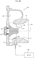
- FIG. 2A is a schematic cross-sectional view of the housing 41 and rotor 42.
- FIG. 2B is a schematic plan view of a rotor 42.
- the rotor 42 is comprised of a center member 421 fixed to a shaft 423 rotatably supported by a roller bearing 424 and a plurality of blades 422 extending from the surface of the center member 421 in the radial direction and axial direction of the rotor 42.
- the center member 421 is fixed to the shaft 423 so that the axis L becomes coaxial with the axis of the shaft 423.
- the rotor 42 is arranged inside of the housing 41 so as to be able to rotate about the axis L. Further, the rotor 42 is arranged inside the housing 41 so that when the rotor rotates, the radial direction end parts of the blades 422 move in the peripheral direction along the inside circumferential surface of the housing 41 in the state with a slight clearance from the inside circumferential surface.
- the rotor 42 has 12 blades 422 of the same shapes arranged at equal intervals.
- the blades 422 are assigned identifying numbers of B1 to B12. Note that, the number of blades 422 is not limited to 12 and may be greater than 12 or less than 12.
- each blade 422 is configured to extend in the radial direction and axial direction of the rotor 42.
- the plurality of blades 422 may be any shapes such as curved shapes so long as able to drive rotation of the rotor 42 by exhaust flowing into the housing 41. Further, the blades 422 do not necessarily have to be arranged at equal intervals. Part or all of the blades 422 may be shapes different from the other blades.
- the housing 41 has a center passage 411 extending through the center of the housing 41 and a ring-shaped passage 412 extending around the center passage 411 and through which exhaust flowing through the exhaust pipe flows.
- a ring-shaped passage 412 is arranged around one end part of the center passage 411 (left side in figure).
- a rotor 42 is arranged inside the center passage 411.
- the other end part of the center passage 411 (right side in figure) is open and forms an outlet 413 from which the exhaust flows out. Therefore, the exhaust flowing through the exhaust pipe 32 flows through the ring-shaped passage 412 and out through the rotor 42 from the outlet 413 of the center passage 411.
- a passage detection sensor 301 is attached at the housing 41 to detect the passage of a blade 422 through a predetermined angular position (predetermined position) inside the housing 41.
- the passage detection sensor 301 detects the passage of a blade 422 in front of the detecting part of the passage detection sensor 301.
- the passage detection sensor 301 is attached to the housing 41 so as to face the radial direction end faces 422a of the blades 422 of the rotor 42 and so as to become substantially parallel to the normal direction of the radial direction end faces 422a of the blades 422.
- the amp unit 300 receives as input the output value of the passage detection sensor 301.
- the amp unit 300 is comprised of an amplifier amplifying the output value of the passage detection sensor 301 and a CPU (microprocessor) utilizing the output value amplified by the amplifier to calculate the angular velocity of the rotor 42 etc. joined together.
- the passage detection sensor 301 and the amp unit 300 are made separate members, but the passage detection sensor 301 may also house the amp unit 300, and the passage detection sensor 301 and amp unit 300 may be joined together.
- an eddy current sensor is used as the passage detection sensor 301.
- An eddy current sensor is a sensor outputting a voltage value corresponding to the distance between a sensor detecting part and a metal substance being measured. Below, referring to FIG. 3 , the principle of detection of the eddy current sensor will be simply explained.
- the eddy current sensor has a coil 301a generating a magnetic field by an AC excitation current at the detecting part. If a blade 422 passes through the magnetic field X generated by the coil 301a, an eddy current Y is generated at the blade 422 so as to cancel out the magnetic field generated by the coil 301a.
- the intensity of the magnetic field X changes due to the eddy current generated at the blade 422 and, as a result, the value of the current flowing through the coil 301a changes. Therefore, by detecting a change of the voltage value derived from the change of the current value flowing through the coil 301a by the eddy current sensor, it is possible to detect if a blade 422 has passed.
- the time when the output value of the eddy current sensor has peaked can be judged as the time when a blade 422 has passed in front of the detecting part of the eddy current sensor 5 (that is, a predetermined angular position inside the housing 41).
- any sensor may be used so long as able to detect passage of the blade 422.
- a magnetic pickup (MPU) sensor may be mentioned.
- An MPU sensor is a sensor having a magnet and a detection coil in a detecting part. In such an MPU sensor, if the magnetic member of a blade approaches or moves away from the MPU sensor, the magnetic flux passing through the detection coil changes. Along with this, the induced electromotive force of the detection coil changes. Due to this, it is possible to detect the passage of a blade 422 at the front of the detecting part of the MPU sensor.
- an eddy current sensor as the passage detection sensor 301 will be explained.
- FIG. 4A and FIG. 4B are views showing the trend in the output value (voltage value) of the passage detection sensor 301 in the case of using an eddy current sensor as the passage detection sensor 301.
- FIG. 4A shows the trend in the output value in the case where the angular velocity of the rotor 42 is relatively slow (for example, speed of rotor 42 is 200,000 rpm)
- FIG. 4B shows the trend in the output value in the case where the angular velocity of the rotor 42 is relatively fast (for example, speed of rotor 42 is 400,000 rpm).
- the output value of the passage detection sensor 301 rapidly rises and falls and the time period between passages of two adjoining blades 422 is maintained constant at a low value.
- the shape error of the blades 422 of the rotor 42 (error within range of shape tolerance) may be mentioned. That is, sometimes shape error occurs in the blades 422 of the rotor 42 due to manufacturing error and aging. Due to this shape error, error arises when calculating the instantaneous angular velocity of the rotor 42.
- FIG. 6 the relationship between the calculated instantaneous angular velocity of the rotor 42 and the shape error of the blades 422 will be explained.
- the design value is used rather than the actual angular intervals between blades. For this reason, even if the rotor 42 rotates by a constant angular velocity, the instantaneous angular velocity ⁇ 1 of the rotor 42 based on the time interval ⁇ t1 from the first blade B1 to the second blade B2 is calculated as being faster than the instantaneous angular velocity ⁇ 2 of the rotor 42 based on the time interval ⁇ t2 from the second blade B2 to the third blade B3. As a result, as shown in FIG. 5 , the instantaneous angular velocity after passage of the first blade B1 is calculated as being faster than the instantaneous angular velocity after passage of the second blade B2.
- FIG. 6 shows an example of shape error when the shapes of blades 422 are shifted overall in the circumferential direction or radial direction.
- the shape error arising at the blades 422 includes error in the axial direction of the rotor 42, error in the curved shapes of the blades, and various other error besides the above shape error. Further, if such shape error occurs in the blades 422, the angular velocity of the rotor 42 can no longer be accurately calculated.
- FIG. 7 is a view showing the trends in the angular velocity of the rotor 42 and the kinetic energy in one cycle of the internal combustion engine 100.
- the abscissa in the figure shows the crank angle of the engine body 1.
- the solid line in FIG. 7 shows the kinetic energy of the rotor 42, while the broken line shows the angular velocity of the rotor 42.
- the angular velocity of the rotor 42 changes according to the crank angle of the engine body 1.
- the exhaust valve of the #1 cylinder opens and exhaust flows out from the combustion chamber 6, the exhaust flowing into the ring-shaped passage 412 inside the housing 41 increases. For this reason, the angular velocity of the rotor 42 increases. Further, along with this, the kinetic energy of the rotor 42 also increases.
- the angular velocity of the rotor 42 rises, then falls. Along with this, the kinetic energy of the rotor 42 increases, then decreases. Further, such angular velocity or kinetic energy trends in the same way in the exhaust stroke of other cylinders 4. Therefore, in a four-cylinder internal combustion engine 100, the angular velocity and kinetic energy of the rotor 42 greatly fluctuate up and down four times in one cycle of the internal combustion engine 100. That is, the angular velocity and kinetic energy of the rotor 42 fluctuate up and down several times in accordance with the number of cylinders of the internal combustion engine 100 during one cycle of the internal combustion engine 100.
- the time interval from the time of start of the exhaust stroke of the #4 cylinder to the time of end of the exhaust stroke corresponds to the combustion interval from the time of start of the combustion stroke of the #2 cylinder to the time of end of the combustion stroke.
- the amp unit 300 sets the angular velocity ⁇ as the current angular velocity value ⁇ z of the rotor 42 and calculates the differential value of the current angular velocity value ⁇ z as the current angular acceleration value ⁇ z '.
- the amp unit 300 sets the current angular velocity value ⁇ z of when the absolute value of the current angular acceleration value ⁇ z ' becomes the extremal value judgment threshold or less as the local minimum angular velocity ⁇ L.
- the previous angular acceleration value ⁇ z-1 ' is a positive value, that is, if the slant of the broken line of FIG.
- the amp unit 300 judges if the elapsed time counting start flag F1 has been set to "0".
- the elapsed time counting start flag F1 is a flag with an initial value which is set to "0".
- the elapsed time counting start flag F1 is set to "0"
- it is set to "1” if passage of a blade 422 is detected by the passage detection sensor 301. Further, if the angular velocity and speed of the rotor 42 are estimated, the flag is again returned to "0".
- the amp unit 300 proceeds to the processing of step S2 if the elapsed time counting start flag F1 is set to "0".
- the amp unit 300 proceeds to the processing of step S5 if the elapsed time counting start flag F1 is set to "1".
- the amp unit 300 judges if passage of a blade 422 has been detected.
- the blade 422 for which passage was detected at this step S3 becomes any one blade of the plurality of blades, that is, a reference blade.
- the amp unit 300 proceeds to the processing of step S4 if passage of a blade 422 is detected.
- the amp unit 300 ends the current processing if passage of a blade 422 is not detected.
- the amp unit 300 sets the elapsed time counting start flag F1 to "1" and starts the counting of the elapsed time t e1 from when the reference blade passes in front of the detecting part of the passage detection sensor 301.
- the positive integer "n” is set to "1", but the positive integer "n” may also be set to a value larger than "1" in accordance with the processing capacity etc. of the CPU of the amp unit 300.
- the amp unit 300 proceeds to the processing of step S9 if the blade 422 for which passage was detected at step S6 is the reference blade. On the other hand, the amp unit 300 ends the current processing if the blade 422 for which passage was detected at step S6 is not the reference blade.
- the amp unit 300 returns the elapsed time t e1 , the number of times "i" of blade passage, and the elapsed time counting start flag F1 to the initial value 0.
- the amp unit 300 judges if the angular velocity ⁇ of the rotor 42 is newly calculated by the control for calculation of the angular velocity of the above-mentioned rotor 42.
- the amp unit 300 proceeds to the processing of step S22 if the angular velocity ⁇ of the rotor 42 is newly calculated.
- the amp unit 300 ends the current processing if the angular velocity co of the rotor 42 is not newly calculated.
- the amp unit 300 reads the newly calculated angular velocity ⁇ of the rotor 42 and the reference blade passing time t m used for the calculation.
- the amp unit 300 judges if there are two points or more of data of the angular velocity co of the rotor 42 read up to then.
- the amp unit 300 proceeds to the processing of step S24 if there are two points or more of data of the angular velocity ⁇ of the rotor 42 read up to then.
- the amp unit 300 ends the current processing if there are not two points or more of data of the angular velocity ⁇ of the rotor 42 read up to then.
- the amp unit 300 calculates the current angular acceleration value ⁇ z ' of the rotor 42. Specifically, the amp unit 300 calculates the current newly read angular velocity ⁇ of the rotor 42 as the current angular velocity value ⁇ z of the rotor 42 and calculates the one previously read angular velocity ⁇ of the rotor 42 as the previous angular velocity value ⁇ z-1 of the rotor 42. Further, the amp unit 300 enters into the following formula (6) the current angular velocity value ⁇ z , the previous angular velocity value ⁇ z-1 , and the reference blade passing time t m read at step S22 to calculate the current angular acceleration value ⁇ z ' of the rotor 42.
- ⁇ z ′ ⁇ z ⁇ ⁇ z ⁇ 1 / t m
- the amp unit 300 judges if the absolute value of the current angular acceleration value ⁇ z ' of the rotor 42 is the extremal value judgment threshold or less.
- the amp unit 300 proceeds to the processing of step S26 if the current angular acceleration value ⁇ z ' of the rotor 42 is the extremal value judgment threshold or less.
- the amp unit 300 ends the current processing if the current angular acceleration value ⁇ z ' of the rotor 42 becomes larger than the extremal value judgment threshold.
- the amp unit 300 judges if the previous angular acceleration value ⁇ z-1 ' of the rotor 42 is a negative value.
- the amp unit 300 proceeds to the processing of step S27 if the previous angular acceleration value ⁇ z-1 ' of the rotor 42 is a negative value.
- the amp unit 300 proceeds to the processing of step S29 if the previous angular acceleration value ⁇ z-1 ' of the rotor 42 is a positive value.
- the amp unit 300 sets the current angular velocity value ⁇ z of the rotor 42 set at step S24 as the local minimum angular velocity ⁇ L.
- the amp unit 300 sets the flag F2 at "1".
- the flag F2 is a flag with an initial value set at "0".
- step S29 the amp unit 300 judges if the flag F2 has been set to "1".
- the amp unit 300 proceeds to the processing of step S30 if the flag F2 has been set to "1". On the other hand, it ends the current processing if the flag F2 has been set to "0".
- the amp unit 300 sets the current angular velocity value ⁇ z of the rotor 42 set at step S24 as the local maximum angular velocity ⁇ H.
- the amp unit 300 returns the flag F2 to the initial value of "0".
- the amp unit 300 judges if the flag F3 has been set to 0.
- the flag F3 is a flag with an initial value (value at start of operation of the internal combustion engine 100) set to "0". It is set to "1" when the local minimum angular velocity ⁇ L is first set after the start of the operation of the internal combustion engine 100.
- the flag F3 is returned to "0" at the time of stopping the operation of the internal combustion engine or the time of starting the operation.
- the amp unit 300 proceeds to the processing of step S42 if the flag F3 is set to "0".
- the amp unit 300 proceeds to the processing of step S44 if the flag F3 is set to "1".
- the amp unit 300 judges if the local minimum angular velocity ⁇ L has first been set from the start of the operation of the internal combustion engine 100. Specifically, the amp unit 300 judges if the local minimum angular velocity ⁇ L has been set after first proceeding to step S27 of the above-mentioned control for estimation of the combustion energy after the start of the operation of the internal combustion engine 100. The amp unit 300 proceeds to the processing of step S43 if the local minimum angular velocity ⁇ L has been set after first proceeding to step S27 of the above-mentioned control for estimation of the combustion energy after the start of the operation of the internal combustion engine 100.
- the amp unit 300 ends the current processing if it does not proceed to step S27 of the above-mentioned control for estimation of the combustion energy after start of the operation of the internal combustion engine 100 and the local minimum angular velocity ⁇ L is still not set.
- the amp unit 300 sets the flag F3 at "1" and starts counting the elapsed time t e2 from when the angular velocity of the rotor 42 becomes the local minimum angular velocity.
- the amp unit 300 calculates the cumulative value of the previous value of the elapsed time t e2 plus the sampling period t smp as the elapsed time t e2 . Note that, the initial value of the elapsed time t e2 is 0.
- step S45 the amp unit 300 judges if the local minimum angular velocity ⁇ L has been changed.
- the amp unit 300 proceeds to the processing of step S46 if the local minimum angular velocity ⁇ L has been changed.
- the amp unit 300 ends the current processing if the local minimum angular velocity ⁇ L is not updated.
- the amp unit 300 calculates the elapsed time t e2 calculated at step S44 as the combustion interval ⁇ tcom.
- the amp unit 300 returns the elapsed time t e2 to the initial value 0 and again starts to count the elapsed time t e2 from when the angular velocity of the rotor 42 becomes the local minimum angular velocity.
- the combustion state estimating device 40 comprises a rotor 42 housed rotatably inside a housing 41 provided on an exhaust pipe 32 (exhaust path) of the engine body 1 having a cylinder 4, having at least one blade 422, and driven to rotate by the energy of the exhaust discharged from each cylinder 4 of the engine body 1, a passage detection sensor 301 provided at the housing 41 and detecting a predetermined position inside the housing 41 being passed by a blade 422 of the rotor 42, and an amp unit 300 (processing system) configured to calculate an angular velocity of the rotor 42 based on the results of detection of the passage detection sensor 301 and calculate at least one of a combustion energy or combustion interval of a cylinder 4 of the engine body 1 based on the angular velocity of the rotor 42.
- a rotor 42 housed rotatably inside a housing 41 provided on an exhaust pipe 32 (exhaust path) of the engine body 1 having a cylinder 4, having at least one blade 422, and driven to rotate by the energy of the exhaust discharged
- a combustion energy or combustion interval of a cylinder 4 of an engine body 1 even without providing an in-cylinder pressure sensor by just providing a combustion state estimating device 40 comprised of a housing 41, rotor 42, passage detection sensor 301, and amp unit 300 in an exhaust pipe 32.
- the method of estimating the combustion energy of each cylinder 4 for example, there is the method of providing each cylinder 4 with an in-cylinder pressure sensor for detecting a pressure in a combustion chamber 6 and calculating the combustion energy of each cylinder 4 based on the detected value of the in-cylinder pressure sensor.
- the same number of in-cylinder pressure sensors as the number of cylinders is necessary.
- the precision of estimation of the combustion energy of each cylinder 4 falls.
- the degree of deterioration along with time of each in-cylinder pressure sensor is liable to differ. This being so, the precision of estimation of the combustion energy of each cylinder 4 falls along with the elapse of time.
- the amp unit 300 is configured to calculate the elapsed time from when any one blade 422 among the blades 422 passes a predetermined position one time as the reference blade passing time each time that any one blade passes the predetermined position a predetermined number of times and to calculate the angular velocity of the rotor 42 based on the reference blade passing time and the number of times any one blade 422 passes a predetermined position during the reference blade passing time.
- the amp unit 300 is configured to calculate the differential value of the angular velocity, that is, the angular acceleration, based on the angular velocity of the rotor 42 and to calculate the combustion energy of the cylinder 4 during the exhaust stroke based on the angular velocity of the rotor 42 when the absolute value of the angular acceleration becomes a predetermined extremal value judgment threshold or less.
- the amp unit 300 is configured to set the angular velocity of the rotor 42 when the absolute value of the angular acceleration becomes the predetermined extremal value judgment threshold or less as the local minimum angular velocity if the previous value of the angular acceleration is a negative value, to set the angular velocity of the rotor 42 when the absolute value of the angular acceleration becomes the predetermined extremal value judgment threshold or less as the local maximum angular velocity if the previous value of the angular acceleration is a positive value, and to calculate the combustion energy of the cylinder 4 during the exhaust stroke based on the local minimum angular velocity and the local maximum angular velocity.
- the amp unit 300 is configured to calculate the combustion interval of each cylinder 4 based on the time period from when the local minimum angular velocity is set to when the local minimum angular velocity is updated.
- the housing 41 of the combustion state estimating device 40 was provided at the upstream side in the direction of flow of exhaust compared with the exhaust post treatment device 33, but it may also be provided at the downstream side.
- the internal combustion engine 100 was not provided with a forced induction system (supercharger or turbocharger), but an internal combustion engine provided with a forced induction system may also be provided with the combustion state estimating device 40 and the combustion state of each cylinder of the internal combustion engine may be estimated.
- a forced induction system supercharger or turbocharger
Landscapes
- Engineering & Computer Science (AREA)
- Chemical & Material Sciences (AREA)
- Combustion & Propulsion (AREA)
- Mechanical Engineering (AREA)
- General Engineering & Computer Science (AREA)
- Analytical Chemistry (AREA)
- Combined Controls Of Internal Combustion Engines (AREA)
Abstract
Description
- The present invention relates to a combustion state estimating device.
-
JP2013-68130A - Here, as the method of estimation of the combustion state of a cylinder, the method of estimating the combustion state of a cylinder based on a detection value of an in-cylinder pressure sensor may be considered. However, in actuality, it is difficult to estimate a combustion state of a cylinder based on a detection value of an in-cylinder pressure sensor. A method of estimating a combustion state of a cylinder without using an in-cylinder pressure sensor is being sought.
- The present invention was made focusing on this problem and has as its object to estimate a combustion state of a cylinder without using an in-cylinder pressure sensor.
- To solve this problem, a combustion state estimating device according to one aspect of the present invention comprises a rotor rotatably housed inside a housing provided on an exhaust path of an engine body having a cylinder, having at least one blade, and driven to rotate by energy of exhaust discharged from the cylinder of the engine body, a passage detection sensor provided in the housing and detecting a predetermined position inside the housing being passed by a blade of the rotor, and a processing system configured to calculate an angular velocity of the rotor based on the results of detection of the passage detection sensor and to calculate at least one of the combustion energy or combustion interval of the cylinder of the engine body based on the angular velocity of the rotor.
- According to the combustion state estimating device according to this aspect of the present invention, it is possible to provide a combustion state estimating device on the exhaust path so as to estimate a combustion state of a cylinder such as a combustion energy or combustion interval of a cylinder of an engine body. For this reason, it is possible to estimate a combustion state of a cylinder without using an in-cylinder pressure sensor.
-
- [
FIG. 1] FIG. 1 is a schematic view of a configuration of an internal combustion engine according to one embodiment of the present invention. - [
FIG. 2A] FIG. 2A is a schematic cross-sectional view of a rotor and housing. - [
FIG. 2B] FIG. 2B is a schematic plan view of a rotor. - [
FIG. 3] FIG. 3 is a view for explaining a principle of detection of an eddy current sensor as a passage detection sensor. - [
FIG. 4A] FIG. 4A is a view showing a trend in output value in the case of using an eddy current sensor as a passage detection sensor. - [
FIG. 4B] FIG. 4B is a view showing a trend in output value in the case of using an eddy current sensor as a passage detection sensor. - [
FIG. 5] FIG. 5 is a view showing one example of the results of calculation of an angular velocity of a compressor wheel in the case of making the rotor rotate by a constant angular velocity. - [
FIG. 6] FIG. 6 is a schematic plan view of a rotor with blades in which shape error has occurred. - [
FIG. 7] FIG. 7 is a view showing trends in angular velocity and kinetic energy of a rotor in one cycle of an internal combustion engine. - [
FIG. 8] FIG. 8 is a view for explaining a method of calculation of a combustion energy of each cylinder and a combustion interval of each cylinder. - [
FIG. 9] FIG. 9 is a flow chart for explaining control for calculation of an angular velocity of a rotor according to one embodiment of the present invention. - [
FIG. 10] FIG. 10 is a flow chart for explaining control for estimation of the combustion energy of each cylinder of an engine body according to one embodiment of the present invention. - [
FIG. 11] FIG. 11 is a flow chart for explaining control for estimation of the combustion interval of each cylinder of an engine body according to one embodiment of the present invention. - Below, referring to the drawings, embodiments of the present invention will be explained in detail. Note that, in the following explanation, similar component elements are assigned the same reference notations.
-
FIG. 1 is a schematic view of the configuration of aninternal combustion engine 100 according to one embodiment of the present invention. - The
internal combustion engine 100 comprises anengine body 1,intake system 20,exhaust system 30, andelectronic control unit 200 for controlling theinternal combustion engine 100. Theinternal combustion engine 100 is a so-called multicylinder internal combustion engine with anengine body 1 having a plurality ofcylinders 4. - The
engine body 1 burns fuel in acombustion chamber 6 formed in eachcylinder 4 to, for example, generate power for driving a vehicle etc. In the present embodiment, theengine body 1 has fourcylinders 4, but the number of cylinders is not particularly limited. For example, it may also be one (single cylinder). Further, in the present embodiment, theengine body 1 burns fuel in acombustion chamber 6 by spark ignition, but the method of combustion of the fuel is also not particularly limited. It is also possible to burn fuel in a combustion chamber by compression ignition. Below, the configuration of theengine body 1 will be explained. - The
engine body 1 comprises acylinder block 2 and acylinder head 3 fixed to a top surface of thecylinder block 2. - The
cylinder block 2 is formed with a plurality ofcylinders 4. Inside of eachcylinder 4, apiston 5 is held receiving the combustion pressure and moving back and forth inside of thecylinder 4. Thepiston 5 is connected through a connecting rod to a crankshaft. Due to the crankshaft, the reciprocating movement of thepiston 5 is converted to rotary motion. The space defined by the inner wall surface of thecylinder head 3, the inner wall surface of acylinder 4, and the top surface of a piston forms acombustion chamber 6. - At the
cylinder head 3,intake ports 7 opening at one side surface of thecylinder head 3 and opening at thecombustion chambers 6 of thecylinders 4 andexhaust ports 8 opening at the other side surface of thecylinder head 3 and opening at thecombustion chambers 6 of thecylinders 4 are formed. - Further, at the
cylinder head 3,intake valves 9 for opening and closing openings of thecombustion chambers 6 andintake ports 7,exhaust valves 10 for opening and closing openings of thecombustion chambers 6 andexhaust ports 8, anintake camshaft 11 driving opening and closing of theintake valves 9, and anexhaust camshaft 12 driving opening and closing of theexhaust valves 10 are attached. - Further, at the
cylinder head 3,fuel injectors 13 for injecting fuel into thecombustion chambers 6 andspark plugs 14 for igniting the air-fuel mixtures of fuel and air injected from thefuel injectors 13 inside of thecombustion chambers 6 are attached. Note that, thefuel injectors 13 may also be attached to inject fuel into theintake ports 7. - The
intake system 20 is a system for guiding air to the insides of thecylinders 4 through theintake ports 7 and comprises anair cleaner 21,intake pipe 22,intake manifold 23, electronically controlledthrottle valve 24, andair flow meter 211. - The
air cleaner 21 removes sand and other foreign matter contained in the air. - The
intake pipe 22 is connected at one end to theair cleaner 21 and is connected at the other end to asurge tank 23a of theintake manifold 23. Due to theintake pipe 22, air (intake air) flowing through theair cleaner 21 to the inside of theintake pipe 22 is guided to thesurge tank 23a of theintake manifold 23. - The
intake manifold 23 is comprised of thesurge tank 23a and a plurality ofintake runners 23b branched from thesurge tank 23a and connected to openings of theintake ports 7 formed at the cylinder head side surfaces. The air introduced into thesurge tank 23a is distributed evenly through theintake runners 23b to the insides of thecylinders 4. - The
throttle valve 24 is provided inside theintake pipe 22. Thethrottle valve 24 is driven by athrottle actuator 25 and changes a passage cross-sectional area of theintake pipe 22 continuously or in stages. By using thethrottle actuator 25 to adjust the opening degree of the throttle valve 24 (below, referred to as the "throttle opening degree"), the amount of intake taken into eachcylinder 4 is adjusted. The throttle opening degree is detected by thethrottle sensor 212. - The
air flow meter 211 is provided inside theintake pipe 22 at the upstream side from thethrottle valve 24. Theair flow meter 211 detects the flow rate of air flowing through the inside of the intake pipe 22 (below, referred to as the "intake amount"). - The
exhaust system 30 is a system for purifying the combustion gas (exhaust) produced inside thecombustion chambers 6 and discharging it to the outside air and is comprised of anexhaust manifold 31,exhaust pipe 32, and exhaustpost-treatment device 33. - The
exhaust manifold 31 is comprised of a plurality ofexhaust runners 31a connected with the openings of theexhaust ports 8 formed at the side surface of the cylinder head and aheader pipe 31b collecting theexhaust runners 31a and bundling them into one. - The
exhaust pipe 32 is connected at one end to theheader pipe 31b of theexhaust manifold 31 and opens at the other end to the outside air. The exhaust discharged from thecylinders 4 through theexhaust ports 8 to theexhaust manifold 31 flows through theexhaust pipe 32 and is discharged to the outside air. - The exhaust
post treatment device 33 is a device for purifying the exhaust then discharging it to the outside air and is comprised of various types of catalysts removing the harmful substances and a filter for trapping harmful substances. - Further, the
internal combustion engine 100 according to the present embodiment further comprises a combustionstate estimating device 40 for estimating the combustion state of eachcylinder 4 such as the combustion energy of eachcylinder 4 or the combustion interval of eachcylinder 4 of theengine body 1. The combustionstate estimating device 40 comprises ahousing 41 connected to theexhaust pipe 32, arotor 42 arranged rotatably inside thehousing 41, apassage detection sensor 301 attached to thehousing 41, and anamp unit 300 configured to calculate the angular velocity of therotor 42 based on the output results of thepassage detection sensor 301 and to estimate the combustion state of eachcylinder 4 such as the combustion energy of eachcylinder 4 and the combustion interval of eachcylinder 4 of theengine body 1 based on the angular velocity of therotor 42. Details of the combustionstate estimating device 40 will be explained later with reference toFIG. 2 on. - The
electronic control unit 200 is comprised of a digital computer and is comprised of components connected to each other by a bidirectional bus such as a ROM (read only memory), RAM (random access memory), CPU (microprocessor), input port, and output port. - The
electronic control unit 200 receives as input through the input port the output signals of the above-mentionedair flow meter 211 andthrottle sensor 212 etc. and, as a signal for calculating the engine speed, an output signal of acrank angle sensor 213 generating an output pulse each time a crankshaft of theengine body 1 rotates by, for example, 15° etc. In this way, theelectronic control unit 200 receives an input through the input port the output signals of various types of sensors required for controlling theinternal combustion engine 100. - Further, the
electronic control unit 200 is electrically connected to thefuel injectors 13, spark plugs 14,throttle actuators 25, and other control parts through the output port. - Further, the
electronic control unit 200 is connected with theamp unit 300 by a CAN (Controller Area Network) communication line and is designed to send and receive data by CAN communication. In the present embodiment, the combustion state of eachcylinder 4 of theengine body 1 estimated by theamp unit 300 is sent to theelectronic control unit 200. Further theelectronic control unit 200 according to the present embodiment is configured to be able to control a parameter relating to combustion in eachcylinder 4, that is, the amount of fuel injection, the amount of intake air, the ignition timing, etc., in accordance with the combustion state of eachcylinder 4 of theengine body 1 sent from theamp unit 300. -
FIG. 2A is a schematic cross-sectional view of thehousing 41 androtor 42.FIG. 2B is a schematic plan view of arotor 42. - As shown in
FIG. 2A , therotor 42 is comprised of acenter member 421 fixed to ashaft 423 rotatably supported by aroller bearing 424 and a plurality ofblades 422 extending from the surface of thecenter member 421 in the radial direction and axial direction of therotor 42. Thecenter member 421 is fixed to theshaft 423 so that the axis L becomes coaxial with the axis of theshaft 423. - The
rotor 42 is arranged inside of thehousing 41 so as to be able to rotate about the axis L. Further, therotor 42 is arranged inside thehousing 41 so that when the rotor rotates, the radial direction end parts of theblades 422 move in the peripheral direction along the inside circumferential surface of thehousing 41 in the state with a slight clearance from the inside circumferential surface. - Further, as shown in
FIG. 2B , therotor 42 according to the present embodiment has 12blades 422 of the same shapes arranged at equal intervals. InFIG. 2B , to facilitate the explanation, theblades 422 are assigned identifying numbers of B1 to B12. Note that, the number ofblades 422 is not limited to 12 and may be greater than 12 or less than 12. In the present embodiment, eachblade 422 is configured to extend in the radial direction and axial direction of therotor 42. However, the plurality ofblades 422 may be any shapes such as curved shapes so long as able to drive rotation of therotor 42 by exhaust flowing into thehousing 41. Further, theblades 422 do not necessarily have to be arranged at equal intervals. Part or all of theblades 422 may be shapes different from the other blades. - Returning to
FIG. 2A , thehousing 41 has acenter passage 411 extending through the center of thehousing 41 and a ring-shapedpassage 412 extending around thecenter passage 411 and through which exhaust flowing through the exhaust pipe flows. Around one end part of the center passage 411 (left side in figure), a ring-shapedpassage 412 is arranged. At the inside of this ring-shapedpassage 412, arotor 42 is arranged inside thecenter passage 411. The other end part of the center passage 411 (right side in figure) is open and forms anoutlet 413 from which the exhaust flows out. Therefore, the exhaust flowing through theexhaust pipe 32 flows through the ring-shapedpassage 412 and out through therotor 42 from theoutlet 413 of thecenter passage 411. - Further, at the
housing 41, to detect the passage of ablade 422 through a predetermined angular position (predetermined position) inside thehousing 41, apassage detection sensor 301 is attached. Thepassage detection sensor 301 detects the passage of ablade 422 in front of the detecting part of thepassage detection sensor 301. In the present embodiment, thepassage detection sensor 301 is attached to thehousing 41 so as to face the radial direction end faces 422a of theblades 422 of therotor 42 and so as to become substantially parallel to the normal direction of the radial direction end faces 422a of theblades 422. - The
amp unit 300 receives as input the output value of thepassage detection sensor 301. Theamp unit 300 is comprised of an amplifier amplifying the output value of thepassage detection sensor 301 and a CPU (microprocessor) utilizing the output value amplified by the amplifier to calculate the angular velocity of therotor 42 etc. joined together. In the present embodiment, thepassage detection sensor 301 and theamp unit 300 are made separate members, but thepassage detection sensor 301 may also house theamp unit 300, and thepassage detection sensor 301 andamp unit 300 may be joined together. - Further, in the present embodiment, an eddy current sensor is used as the
passage detection sensor 301. An eddy current sensor is a sensor outputting a voltage value corresponding to the distance between a sensor detecting part and a metal substance being measured. Below, referring toFIG. 3 , the principle of detection of the eddy current sensor will be simply explained. - The eddy current sensor has a
coil 301a generating a magnetic field by an AC excitation current at the detecting part. If ablade 422 passes through the magnetic field X generated by thecoil 301a, an eddy current Y is generated at theblade 422 so as to cancel out the magnetic field generated by thecoil 301a. The intensity of the magnetic field X changes due to the eddy current generated at theblade 422 and, as a result, the value of the current flowing through thecoil 301a changes. Therefore, by detecting a change of the voltage value derived from the change of the current value flowing through thecoil 301a by the eddy current sensor, it is possible to detect if ablade 422 has passed. Specifically, the time when the output value of the eddy current sensor has peaked can be judged as the time when ablade 422 has passed in front of the detecting part of the eddy current sensor 5 (that is, a predetermined angular position inside the housing 41). - Note that, as the
passage detection sensor 301 for detecting passage of ablade 422, any sensor may be used so long as able to detect passage of theblade 422. As such a sensor, for example, a magnetic pickup (MPU) sensor may be mentioned. An MPU sensor is a sensor having a magnet and a detection coil in a detecting part. In such an MPU sensor, if the magnetic member of a blade approaches or moves away from the MPU sensor, the magnetic flux passing through the detection coil changes. Along with this, the induced electromotive force of the detection coil changes. Due to this, it is possible to detect the passage of ablade 422 at the front of the detecting part of the MPU sensor. In the following explanation, the case of use of an eddy current sensor as thepassage detection sensor 301 will be explained. -
FIG. 4A and FIG. 4B are views showing the trend in the output value (voltage value) of thepassage detection sensor 301 in the case of using an eddy current sensor as thepassage detection sensor 301.FIG. 4A shows the trend in the output value in the case where the angular velocity of therotor 42 is relatively slow (for example, speed ofrotor 42 is 200,000 rpm), whileFIG. 4B shows the trend in the output value in the case where the angular velocity of therotor 42 is relatively fast (for example, speed ofrotor 42 is 400,000 rpm). - When using an eddy current sensor as the
passage detection sensor 301, the shorter the distance between the detecting part of thepassage detection sensor 301 and an object passing in front of it (in the present embodiment, a blade 422), the larger the output value. Therefore, if ablade 422 passes in front of the detecting part of thepassage detection sensor 301, the output value of thepassage detection sensor 301 rapidly increases. Accordingly, the output changing to a spike inFIG. 4A and FIG. 4B means the passage of ablade 422. Note that, Nos. B1 to B12 ofFIG. 4A and FIG. 4B are identifying numbers of theblades 422 passing in front of the detecting part of thepassage detection sensor 301. - As shown in
FIG. 4A , if the angular velocity of therotor 42 is relatively slow, along with the passage of ablade 422, the output value of thepassage detection sensor 301 rapidly rises and falls and the time period between passages of two adjoiningblades 422 is maintained constant at a low value. - On the other hand, as shown in
FIG. 4B , if the angular velocity of therotor 42 is relatively fast, before the output value of thepassage detection sensor 301 which had risen along with the passage of oneblade 422 falls to the lowest value, the output value of thepassage detection sensor 301 starts to rise along with the passage of thenext blade 422. Therefore, as shown inFIG. 4B , even in the time period between passages of two adjoiningblades 422, the output value of thepassage detection sensor 301 is not maintained constant. However, in this case as well, the timing where the output value of thepassage detection sensor 301 becomes maximum shows the passage of ablade 422, so it is possible to accurately detect the passage of ablade 422 in front of the detecting part of thepassage detection sensor 301. - In this way, the
passage detection sensor 301 can accurately detect the passage of ablade 422 in front of the detecting part of thepassage detection sensor 301. For this reason, as one example of the method of calculation of the angular velocity of therotor 42 using thepassage detection sensor 301, the method of calculating the angular velocity of therotor 42 each time ablade 422 passes in front of thepassage detection sensor 301 based on the time interval from the passage of any one blade among the blades 422 (below, referred to as the "reference blade") in front of thepassage detection sensor 301 to when the blade passing in front of thepassage detection sensor 301 after the reference blade passes. - Below, referring to
FIG. 4A , one example of the method of calculation of the angular velocity of therotor 42 using thispassage detection sensor 301 will be explained. - In the example shown in
FIG. 4A , the time when the output value of thepassage detection sensor 301 peaks due to a first blade B1 passing in front of thepassage detection sensor 301 is made the time t1. Similarly, the times when the output value of thepassage detection sensor 301 peaks due to a second blade B2, a third blade B3, and a fourth blade B4 passing in front of thepassage detection sensor 301 are made the times t2, t3, and t4. - In this case, the time interval Δt1 from when the first blade B1 passes in front of the
passage detection sensor 301 to when the second blade B2 passes becomes t2-t1. On the other hand, in the present embodiment, 12 blades are provided at equal intervals, so the angular interval between the first blade B1 and the second blade B2 basically becomes (2π/12)[rad]. Therefore, an instantaneous angular velocity ω1[rad/s] of therotor 42 from when the first blade B1 passes in front of thepassage detection sensor 301 to when the second blade B2 passes (below, referred to as the "instantaneous angular velocity after passage of the first blade") becomes 2π/(12×Δt1). - Similarly, the time interval Δt2 from when the second blade B2 passes in front of the
passage detection sensor 301 to when the third blade B3 passes becomes t3-t2, while the time interval Δt3 from when the third blade B3 passes to when the fourth blade B4 passes becomes t4-t3. Therefore, the instantaneous angular velocity ω2 of therotor 42 from when the second blade B2 passes in front of thepassage detection sensor 301 to when the third blade B3 passes, that is, the instantaneous angular velocity ω2 after the passage of the second blade, becomes 2π/(12×Δt2). Similarly, the instantaneous angular velocity ω3 of therotor 42 from when the third blade B3 passes in front of thepassage detection sensor 301 to when the fourth blade B4 passes, that is, the instantaneous angular velocity ω3 after the passage of the third blade, becomes 2π/(12×Δt3). - Therefore, if representing the identifying number of the
blades 422 by "i", if calculating the time interval Δti between passages of an adjoining pair of blades 422 (that is, the i-th blade Bi and (i+1)th blade B(i+1)) in front of thepassage detection sensor 301 based on the output of thepassage detection sensor 301, it is possible to calculate the instantaneous angular velocity coi after passage of the i-th blade Bi based on the time interval Δti and the angular interval between the adjoining pair ofblades 422. - Specifically, by dividing the angular interval αi between the adjoining pair of
blades 422 like in the following formula (1) by the time interval Δti of passage between theseblades 422, it is possible to calculate the instantaneous angular velocity coi after passage of the i-th blade.
- Further, in the case, like the present embodiment, of the
rotor 42 withblades 422 provided at equal intervals in the circumferential direction, if designating the total number of theblades 422 as "p", the angular interval αi becomes (2π/p). Therefore, the instantaneous angular velocity ωi after passage of the i-th blade can be calculated by the following formula (2):
- In this regard, however, it will be understood that if using such a method of calculation to calculate the angular velocity of the
rotor 42, that is, if calculating the angular velocity of therotor 42 based on the time interval Δti from when the reference blade passes in front of thepassage detection sensor 301 to when the blade passing in front of thepassage detection sensor 301 after the reference blade passes, error arises between the actual angular velocity and the calculated angular velocity (calculation error). -
FIG. 5 is a view showing one example of the results of calculation when calculating the angular velocity of therotor 42 by the above-mentioned method of calculation if making therotor 42 rotate by a certain angular velocity. InFIG. 5 , the abscissa shows the identifying numbers of theblades 422, while the ordinate shows the instantaneous angular velocity of therotor 42 after passage of the blade with the corresponding blade number. - In the example shown in
FIG. 5 , therotor 42 is made to rotate by a certain angular velocity. Therefore, the instantaneous angular velocity of therotor 42 calculated at this time should also become a constant value. However, in actuality, as shown inFIG. 5 , the calculated instantaneous angular velocity of therotor 42 will not necessarily become constant after passage of eachblade 422. For example, in the example shown inFIG. 5 , the instantaneous angular velocity of therotor 42 after passage of the #2 blade becomes slower than the instantaneous angular velocity of therotor 42 after passage of the #1 blade. - In this way, as one of the reasons why the calculated instantaneous angular velocity of the
rotor 42 will not become a constant value, the shape error of theblades 422 of the rotor 42 (error within range of shape tolerance) may be mentioned. That is, sometimes shape error occurs in theblades 422 of therotor 42 due to manufacturing error and aging. Due to this shape error, error arises when calculating the instantaneous angular velocity of therotor 42. Below, referring toFIG. 6 , the relationship between the calculated instantaneous angular velocity of therotor 42 and the shape error of theblades 422 will be explained. -
FIG. 6 is a schematic plan view of arotor 42 in which shape error occurs in theblades 422. The broken line inFIG. 6 shows the shape of theblades 422 in the case where theblades 422 of therotor 42 are formed as designed. In the example shown inFIG. 6 , it will be understood that the second blade B2 and the 10th blade B10 have shape error with respect to the design blade shape. Specifically, the second blade B2 becomes a shape shifted to the first blade side in the circumferential direction with respect to the design shape. Further, the 10th blade B10 becomes a shape shifted to the outside in the radial direction with respect to the design shape. - If in this way error occurs in the blade shapes, the angular interval α between blades changes. In the example shown in
FIG. 6 , the shape of the second blade B2 becomes a shape shifted in the circumferential direction with respect to the design shape. As a result, in the region facing thepassage detection sensor 301, the actual angular interval between the first blade B1 and the second blade B2 becomes α1 smaller than the design value β1. Conversely, the actual angular interval between the second blade B2 and the third blade B3 becomes α2 larger than the design value β2. Therefore, the actual angular interval α1 between the first blade B1 and the second blade B2 becomes smaller than the actual angular interval α2 between the second blade B2 and the third blade B3. - On the other hand, in calculating the angular velocity, the design value is used rather than the actual angular intervals between blades. For this reason, even if the
rotor 42 rotates by a constant angular velocity, the instantaneous angular velocity ω1 of therotor 42 based on the time interval Δt1 from the first blade B1 to the second blade B2 is calculated as being faster than the instantaneous angular velocity ω2 of therotor 42 based on the time interval Δt2 from the second blade B2 to the third blade B3. As a result, as shown inFIG. 5 , the instantaneous angular velocity after passage of the first blade B1 is calculated as being faster than the instantaneous angular velocity after passage of the second blade B2. - Further, in the example shown in
FIG. 6 , the 10th blade BI0 becomes a shape shifted to the outside in the circumferential direction with respect to the design shape. As a result, the actual angular interval between the ninth blade B9 and the 10th blade B10 becomes α9 smaller than the design value β9. Further, the actual angular interval between the 10th blade B10 and the 11th blade B11 becomes α10 larger than the design value β10. As a result, even if therotor 42 rotates by a certain angular velocity, the instantaneous angular velocity after passage of the ninth blade B9 is calculated as one faster than the instantaneous angular velocity after passage of the 10th blade B10. - Note that,
FIG. 6 shows an example of shape error when the shapes ofblades 422 are shifted overall in the circumferential direction or radial direction. However, the shape error arising at theblades 422 includes error in the axial direction of therotor 42, error in the curved shapes of the blades, and various other error besides the above shape error. Further, if such shape error occurs in theblades 422, the angular velocity of therotor 42 can no longer be accurately calculated. - Therefore, in the present embodiment, rather than, like with the above-mentioned method of calculation, calculating the angular velocity of the
rotor 42 based on the time interval from when a reference blade passes in front of thepassage detection sensor 301 to when the blade passing in front of thepassage detection sensor 301 after the reference blade passes, that is, the time required for passage between adjoining blades, the angular velocity of therotor 42 is calculated based on the time interval from when the reference blade passes in front of thepassage detection sensor 301 to when the reference blade again passes in front of thepassage detection sensor 301, that is, the time required for therotor 42 to turn one time. - In this way, by calculating the angular velocity of the
rotor 42 based on the time required for therotor 42 to turn one time, even if shape error occurs in theblades 422, it is possible to calculate the angular velocity of therotor 42 without being affected by the shape error. For example, if the reference blade is made the first blade B1, as shown in the example shown inFIG. 6 , even if the actual angular interval α1 between the first blade B1 and the second blade B2 and the actual angular interval α9 between the ninth blade B9 and the 10th blade B10 respectively differ from the design values β1 and β9, the angular interval from the first blade B1 to the first blade B1 always becomes constant at 2π [rad]. Further, even if the first blade B1 itself changes in shape, the angular interval from the first blade B1 to the first blade B1 always becomes constant at 2π [rad]. - For this reason, by calculating the angular velocity of the
rotor 42 based on the time required for therotor 42 to turn one time, it is possible to accurately calculate the angular velocity of therotor 42 without being affected by shape error of theblades 422. - Further, as a result of intensive research of the inventors, it was learned that if it is possible to accurately calculate the angular velocity of the
rotor 42, it becomes possible to accurately estimate the combustion state of eachcylinder 4 of theengine body 1 based on the calculated angular velocity of therotor 42. Below, the method of estimating the combustion state of eachcylinder 4 of theengine body 1 based on the angular velocity of therotor 42 will be explained. - Inside of the
housing 41, therotor 42 rotates, but the kinetic energy KE of therotor 42 can be calculated by the following formula (3):
- In formula (3), "I" is the inertia moment of the
rotor 42, while "ω" is the angular velocity of therotor 42. The inertia moment I of therotor 42 can be found by calculations in advance etc. from the shape and material of therotor 42. Therefore, by finding the angular velocity of therotor 42, it is possible to calculate the kinetic energy of therotor 42 at the point of time of finding the angular velocity. - Therefore, in the present embodiment, during the operation of the
internal combustion engine 100, the angular velocity co of therotor 42 is calculated by theamp unit 300. Further, the kinetic energy of therotor 42 is calculated by theamp unit 300 by formula (3). In the present embodiment, it is possible to accurately estimate the angular velocity ω of therotor 42 without being affected by the shape error of therotor 42, so it is possible to accurately calculate the kinetic energy of therotor 42. - If, in this way, it is possible to accurately calculate the kinetic energy of the
rotor 42, based on the calculated kinetic energy, if theengine body 1 has a plurality ofcylinders 4, it is possible to estimate the combustion state of eachcylinder 4 such as the combustion energy generated when burning fuel in thecombustion chamber 6 of eachcylinder 4 or the combustion interval of the eachcylinder 4. Further, if theengine body 1 has a single cylinder, it is possible to estimate the combustion state of the single cylinder such as the combustion energy generated when burning fuel in the combustion chamber of the single cylinder or the combustion interval. Below, the relationship between the kinetic energy of therotor 42 and the combustion state of eachcylinder 4 in the case where theengine body 1 has a plurality ofcylinders 4 will be explained. -
FIG. 7 is a view showing the trends in the angular velocity of therotor 42 and the kinetic energy in one cycle of theinternal combustion engine 100. The abscissa in the figure shows the crank angle of theengine body 1. The solid line inFIG. 7 shows the kinetic energy of therotor 42, while the broken line shows the angular velocity of therotor 42. - As shown in
FIG. 7 , the angular velocity of therotor 42 changes according to the crank angle of theengine body 1. In the example shown inFIG. 7 , first, if the exhaust valve of the #1 cylinder opens and exhaust flows out from thecombustion chamber 6, the exhaust flowing into the ring-shapedpassage 412 inside thehousing 41 increases. For this reason, the angular velocity of therotor 42 increases. Further, along with this, the kinetic energy of therotor 42 also increases. - After that, at the end of the exhaust stroke of the #1 cylinder, the flow rate of exhaust flowing out from the
combustion chamber 6 decreases. As a result, the angular velocity of therotor 42 decreases. Further, along with this, the kinetic energy of therotor 42 decreases. - Therefore, as will be understood from
FIG. 7 , during the exhaust stroke of the #1 cylinder, the angular velocity of therotor 42 rises, then falls. Along with this, the kinetic energy of therotor 42 increases, then decreases. Further, such angular velocity or kinetic energy trends in the same way in the exhaust stroke ofother cylinders 4. Therefore, in a four-cylinderinternal combustion engine 100, the angular velocity and kinetic energy of therotor 42 greatly fluctuate up and down four times in one cycle of theinternal combustion engine 100. That is, the angular velocity and kinetic energy of therotor 42 fluctuate up and down several times in accordance with the number of cylinders of theinternal combustion engine 100 during one cycle of theinternal combustion engine 100. - Here, if considering the #4 cylinder as an example, the amount of rise of the kinetic energy of the
rotor 42 during the exhaust stroke of the #4 cylinder (ΔKE inFIG. 7 ) is proportional to the exhaust energy of the exhaust discharged from thecombustion chamber 6 of the #4 cylinder. Similarly, the amounts of rise of the kinetic energy of therotor 42 during the exhaust strokes of the #1 cylinder, #3 cylinder, and #2 cylinder are proportional to the exhaust energies of the exhausts respectively discharged from thecombustion chambers 6 of the #1 cylinder, #3 cylinder, and #2 cylinder. Here, the exhaust energy of the exhaust discharged from eachcylinder 4 basically is proportional to the combustion energy generated when fuel is burned in thecombustion chamber 6 of eachcylinder 4, that is, the torque (combustion torque) generated due to combustion of fuel in thecombustion chamber 6 of eachcylinder 4. - Therefore, by comparing the amount of rise of the kinetic energy of the
rotor 42 in the exhaust stroke of eachcylinder 4 between cylinders, it is possible to detect the difference in combustion energy (combustion torque) between cylinders. Specifically, it is possible to detect the difference in combustion energy (combustion torque) between cylinders based on the difference (ΔKE) between the minimum value of the kinetic energy of therotor 42 at the time of start of the exhaust stroke of eachcylinder 4 and the maximum value of the kinetic energy of therotor 42 during the exhaust stroke of thecylinder 4. Acylinder 4 with a large difference between these minimum value and maximum value can be judged as acylinder 4 with a large combustion energy (combustion torque), while acylinder 4 with a small difference between these minimum value and maximum value can be judged as acylinder 4 with a small combustion energy (combustion torque). - Further, if considering the #4 cylinder as an example, the time interval from the time of start of the exhaust stroke of the #4 cylinder to the time of end of the exhaust stroke (Δtcom in
FIG. 7 ), that is, the time period during which therotor 42 is made to rotate by the exhaust discharged from thecombustion chamber 6 of the #4 cylinder, corresponds to the combustion interval from the time of start of the combustion stroke of the #2 cylinder to the time of end of the combustion stroke. In the same way, the time intervals from the times of start of exhaust strokes of the #1 cylinder, #3 cylinder, and #2 cylinder to the times of end of the exhaust strokes respectively correspond to the combustion intervals from the times of start of the combustion strokes to the times of end of the combustion strokes of the #3 cylinder, #4 cylinder, and #1 cylinder. - Therefore, by comparing the time interval from the time of start of the exhaust stroke of each
cylinder 4 to the time of end of the exhaust stroke between cylinders, it is possible to detect the difference in combustion intervals between cylinders. - If in this way it is possible to detect the difference in combustion energy (combustion torque) or the difference in combustion intervals between cylinders, for example, it would be possible to control the fuel injection amount, the amount of intake air, the ignition timing, and other parameters relating to combustion in each
cylinder 4 by theelectronic control unit 200 by feedback control or feed forward control. Due to this, it becomes possible to keep the difference in combustion energy (combustion torque) or the difference in combustion intervals between cylinders to the minimum extent. Further, if theengine body 1 has a single cylinder, by calculating at all times the combustion state of the single cylinder such as the combustion energy (combustion torque) or combustion interval of the single cylinder, for example even when for example a difference in combustion state arises in the steady state (state with no load fluctuations), it is possible to control the fuel injection amount, the amount of intake air, the ignition timing, or other parameter relating to combustion in eachcylinder 4 by theelectronic control unit 200 by feedback control or feed forward control so as to match the combustion state. -
FIG. 8 is a view for explaining the method of calculation of the combustion energy ΔKE of eachcylinder 4 and the combustion interval Δtcom of eachcylinder 4. The abscissa in the figure shows the crank angle of theengine body 1. The solid line inFIG. 8 shows the kinetic energy of therotor 42 while the broken line shows the angular velocity of therotor 42. - To calculate the amount of rise of the kinetic energy of the
rotor 42 during the exhaust stroke of eachcylinder 4, that is, the combustion energy ΔKE generated when making fuel burn in thecombustion chamber 6 of eachcylinder 4, it is necessary to respectively calculate the minimum value of the kinetic energy of therotor 42 at the time of start of the exhaust stroke of eachcylinder 4 and the maximum value of the kinetic energy of therotor 42 during the exhaust stroke of thecylinder 4. - Here, if using the #4 cylinder as an example and considering the differential value ω' of the angular velocity co of the rotor 42 (below, referred to as the "angular acceleration") (=dω/dt; slant of broken line of
FIG. 8 ), as shown inFIG. 8 , the angular acceleration ω' becomes 0 at the time of start of the exhaust stroke of eachcylinder 4 where the kinetic energy of therotor 42 becomes the minimum value (local minimum value). Further, the angular acceleration ω' becomes 0 even at a certain time during the exhaust stroke of eachcylinder 4 where the kinetic energy of therotor 42 becomes the maximum value (local maximum value). - Therefore, each time calculating the angular velocity ω of the
rotor 42, theamp unit 300 according to present embodiment sets the angular velocity ω as the current angular velocity value ωz of therotor 42 and calculates the differential value of the current angular velocity value ωz as the current angular acceleration value ωz'. Further theamp unit 300 sets the current angular velocity value ωz of when the absolute value of the current angular acceleration value ωz' becomes the preset close to 0 value of the extremal value judgment threshold or less as the angular velocity ωL at the time of start of the exhaust stroke of each cylinder 4 (below, referred to as the "local minimum angular velocity") or as the angular velocity ωH at the time during the exhaust stroke of eachcylinder 4 where the kinetic energy of therotor 42 becomes the maximum value (local maximum value) (below, referred to as the "local maximum angular velocity"). - Note that, regarding the current angular velocity value ωz when the absolute value of the current angular acceleration value ωz' becomes the extremal value judgment threshold or less, whether the current angular velocity value ωz is the local minimum angular velocity ωL or the local maximum angular velocity ωH can be judged by judging if the immediately preceding calculated previous angular acceleration value ωz-1' is a positive value.
- Specifically, if the previous angular acceleration value ωz-1' is a negative value, that is, if the slant of the broken line in
FIG. 8 is negative, it can be judged that the angular velocity has turned from a fall to a rise. Therefore, theamp unit 300 according to present embodiment, in this case, sets the current angular velocity value ωz of when the absolute value of the current angular acceleration value ωz' becomes the extremal value judgment threshold or less as the local minimum angular velocity ωL. On the other hand, if the previous angular acceleration value ωz-1' is a positive value, that is, if the slant of the broken line ofFIG. 8 is positive, it can be judged that this is a time when the angular velocity ω turns from a rise to a fall. Therefore, theamp unit 300 according to present embodiment, in this case, sets the current angular velocity value ωz of when the absolute value of the current angular acceleration value ωz' becomes an extremal value judgment threshold or less as the local maximum angular velocity ωH. - If entering the thus set local minimum angular velocity ωL and local maximum angular velocity ωH into formula (3), it is possible to calculate the minimum value of the kinetic energy of the
rotor 42 at the time of start of the exhaust stroke of eachcylinder 4 and the maximum value of the kinetic energy of therotor 42 during the exhaust stroke of thecylinder 4. Further, if subtracting from the thus calculated maximum value of the kinetic energy the minimum value, it is possible to calculate the combustion energy ΔKE generated when making fuel burn in thecombustion chamber 6 of eachcylinder 4. - Further, the combustion interval Δtcom of each
cylinder 4, as explained above, corresponds to the time interval from the start of the exhaust stroke of eachcylinder 4 to the end of the exhaust stroke. Therefore, the combustion interval Δtcom of eachcylinder 4 matches the time from when the local minimum angular velocity ωL is set to when the local minimum angular velocity ωL is next set. Therefore, theamp unit 300 according to present embodiment measures the time from when the local minimum angular velocity ωL is set to when the local minimum angular velocity ωL is next set so as to calculate the combustion interval of eachcylinder 4. - Note that, aside from this as well, for example, it is also possible to count the time from when calculating the minimum value of the kinetic energy of the
rotor 42 to when next calculating the minimum value of the kinetic energy of therotor 42 so as to calculate the combustion interval Δtcom of eachcylinder 4. - Below, the control for estimation of the combustion energy of each
cylinder 4 and the combustion interval of eachcylinder 4 of theengine body 1 utilizing the output value of thepassage detection sensor 301 according to the present embodiment will be explained. - First, referring to
FIG. 9 , control for calculation of the angular velocity of therotor 42 which theamp unit 300 performs will be explained. Theamp unit 300 repeatedly performs this routine by a predetermined processing period (=sampling period tsmp). - At step S1, the
amp unit 300 reads the output value of thepassage detection sensor 301. - At step S2, the
amp unit 300 judges if the elapsed time counting start flag F1 has been set to "0". The elapsed time counting start flag F1 is a flag with an initial value which is set to "0". When the elapsed time counting start flag F1 is set to "0", it is set to "1" if passage of ablade 422 is detected by thepassage detection sensor 301. Further, if the angular velocity and speed of therotor 42 are estimated, the flag is again returned to "0". Theamp unit 300 proceeds to the processing of step S2 if the elapsed time counting start flag F1 is set to "0". On the other hand, theamp unit 300 proceeds to the processing of step S5 if the elapsed time counting start flag F1 is set to "1". - At step S3, the
amp unit 300 judges if passage of ablade 422 has been detected. Theblade 422 for which passage was detected at this step S3 becomes any one blade of the plurality of blades, that is, a reference blade. Theamp unit 300 proceeds to the processing of step S4 if passage of ablade 422 is detected. On the other hand, theamp unit 300 ends the current processing if passage of ablade 422 is not detected. - At step S4, the
amp unit 300 sets the elapsed time counting start flag F1 to "1" and starts the counting of the elapsed time te1 from when the reference blade passes in front of the detecting part of thepassage detection sensor 301. - At step S5, the
amp unit 300 calculates the previous value of the elapsed time te1 plus the sampling period tsmp as the elapsed time te1. Note that, the initial value of the elapsed time te is 0. - At step S6, the
amp unit 300 judges if passage of ablade 422 has been detected by thepassage detection sensor 301. Theamp unit 300 proceeds to the processing of step S7 if passage of ablade 422 is detected by thepassage detection sensor 301. On the other hand, theamp unit 300 ends the current processing if passage of ablade 422 is not detected by thepassage detection sensor 301. - At step S7, the
amp unit 300 calculates the number of times "i" of blade passage from when the reference blade passed in front of the detecting part of thepassage detection sensor 301. Specifically, theamp unit 300 calculates the previous value of the number of times "i" of blade passage plus 1 as the number of times "i" of blade passage. Note that, the initial value of the number of times "i" of blade passage is 0. - At step S8, the
amp unit 300 judges if theblade 422 for which passage was detected at step S6 is the reference blade. Specifically, theamp unit 300 judges if the number of times "i" of blade passage has become a value found by multiplying the total number of blades (in the present embodiment, 12) by a positive integer "n". - If setting the positive integer "n" to for, example, "1", it is possible to judge at step S8 if the
rotor 42 has turned one time, while if setting it to, for example, "2", it is possible to judge at step S8 if therotor 42 has turned two times. That is, it is possible to adjust the timing of estimation of the angular velocity of therotor 42 in accordance with the positive integer "n" and possible to adjust the number of estimated data of the angular velocity of therotor 42 per unit time. In the present embodiment, the positive integer "n" is set to "1", but the positive integer "n" may also be set to a value larger than "1" in accordance with the processing capacity etc. of the CPU of theamp unit 300. - The
amp unit 300 proceeds to the processing of step S9 if theblade 422 for which passage was detected at step S6 is the reference blade. On the other hand, theamp unit 300 ends the current processing if theblade 422 for which passage was detected at step S6 is not the reference blade. - At step S9, the
amp unit 300 sets the elapsed time te1 calculated at step S5 as the reference blade passing time tm. That is, theamp unit 300 sets the positive integer "n" of the present embodiment as "1", so sets the time period from when detecting a first passage of the reference blade in front of the detecting part of thepassage detection sensor 301 until when detecting the next passage of the reference blade in front of the detecting part of the passage detection sensor 301 (time required for therotor 42 to turn once) as the reference blade passing time tm. - At step S10, the
amp unit 300 calculates the angular velocity of therotor 42 based on the reference blade passing time tm. Specifically, theamp unit 300 enters the reference blade passing time tm into the following formula (4) to calculate the angular velocity ω of therotor 42. Note that, at step S10, it is also possible to enter the reference blade passing time tm into the following formula (5) to also calculate the speed N of therotor 42.

- At step S11, the
amp unit 300 returns the elapsed time te1, the number of times "i" of blade passage, and the elapsed time counting start flag F1 to theinitial value 0. - Next, referring to
FIG. 10 , the control for estimation of the combustion energy of eachcylinder 4 of theengine body 1 which theamp unit 300 performs will be explained. Theamp unit 300 repeatedly performs this routine by a predetermined processing period (=sampling period tsmp). - At step S21, the
amp unit 300 judges if the angular velocity ω of therotor 42 is newly calculated by the control for calculation of the angular velocity of the above-mentionedrotor 42. Theamp unit 300 proceeds to the processing of step S22 if the angular velocity ω of therotor 42 is newly calculated. On the other hand, theamp unit 300 ends the current processing if the angular velocity co of therotor 42 is not newly calculated. - At step S22, the
amp unit 300 reads the newly calculated angular velocity ω of therotor 42 and the reference blade passing time tm used for the calculation. - At step S23, the
amp unit 300 judges if there are two points or more of data of the angular velocity co of therotor 42 read up to then. Theamp unit 300 proceeds to the processing of step S24 if there are two points or more of data of the angular velocity ω of therotor 42 read up to then. On the other hand, theamp unit 300 ends the current processing if there are not two points or more of data of the angular velocity ω of therotor 42 read up to then. - At step S24, the
amp unit 300 calculates the current angular acceleration value ωz' of therotor 42. Specifically, theamp unit 300 calculates the current newly read angular velocity ω of therotor 42 as the current angular velocity value ωz of therotor 42 and calculates the one previously read angular velocity ω of therotor 42 as the previous angular velocity value ωz-1 of therotor 42. Further, theamp unit 300 enters into the following formula (6) the current angular velocity value ωz, the previous angular velocity value ωz-1, and the reference blade passing time tm read at step S22 to calculate the current angular acceleration value ωz' of therotor 42.
- At step S25, the
amp unit 300 judges if the absolute value of the current angular acceleration value ωz' of therotor 42 is the extremal value judgment threshold or less. Theamp unit 300 proceeds to the processing of step S26 if the current angular acceleration value ωz' of therotor 42 is the extremal value judgment threshold or less. On the other hand, theamp unit 300 ends the current processing if the current angular acceleration value ωz' of therotor 42 becomes larger than the extremal value judgment threshold. - At step S26, the
amp unit 300 judges if the previous angular acceleration value ωz-1' of therotor 42 is a negative value. Theamp unit 300 proceeds to the processing of step S27 if the previous angular acceleration value ωz-1' of therotor 42 is a negative value. On the other hand, theamp unit 300 proceeds to the processing of step S29 if the previous angular acceleration value ωz-1' of therotor 42 is a positive value. - At step S27, the
amp unit 300 sets the current angular velocity value ωz of therotor 42 set at step S24 as the local minimum angular velocity ωL. - At step S28, the
amp unit 300 sets the flag F2 at "1". The flag F2 is a flag with an initial value set at "0". - At step S29, the
amp unit 300 judges if the flag F2 has been set to "1". Theamp unit 300 proceeds to the processing of step S30 if the flag F2 has been set to "1". On the other hand, it ends the current processing if the flag F2 has been set to "0". - At step S30, the
amp unit 300 sets the current angular velocity value ωz of therotor 42 set at step S24 as the local maximum angular velocity ωH. - At step S31, the
amp unit 300 enters into the following formula (7) the local minimum angular velocity ωL and local maximum angular velocity ωH set at step S27 and step S30 to calculate the amount of rise ΔKE of the kinetic energy of therotor 42, that is, the combustion energy generated when burning fuel in acombustion chamber 6 of acylinder 4 during the current exhaust stroke:
- At step S32, the
amp unit 300 returns the flag F2 to the initial value of "0". - Next, referring to
FIG. 11 , the control for estimation of the combustion interval of eachcylinder 4 of theengine body 1 performed by theamp unit 300 during the operation of theinternal combustion engine 100 will be explained. Theamp unit 300 repeatedly performs this routine by a predetermined processing period (=sampling period tsmp). - At step S41, the
amp unit 300 judges if the flag F3 has been set to 0. The flag F3 is a flag with an initial value (value at start of operation of the internal combustion engine 100) set to "0". It is set to "1" when the local minimum angular velocity ωL is first set after the start of the operation of theinternal combustion engine 100. The flag F3 is returned to "0" at the time of stopping the operation of the internal combustion engine or the time of starting the operation. Theamp unit 300 proceeds to the processing of step S42 if the flag F3 is set to "0". On the other hand, theamp unit 300 proceeds to the processing of step S44 if the flag F3 is set to "1". - At step S42, the
amp unit 300 judges if the local minimum angular velocity ωL has first been set from the start of the operation of theinternal combustion engine 100. Specifically, theamp unit 300 judges if the local minimum angular velocity ωL has been set after first proceeding to step S27 of the above-mentioned control for estimation of the combustion energy after the start of the operation of theinternal combustion engine 100. Theamp unit 300 proceeds to the processing of step S43 if the local minimum angular velocity ωL has been set after first proceeding to step S27 of the above-mentioned control for estimation of the combustion energy after the start of the operation of theinternal combustion engine 100. On the other hand, theamp unit 300 ends the current processing if it does not proceed to step S27 of the above-mentioned control for estimation of the combustion energy after start of the operation of theinternal combustion engine 100 and the local minimum angular velocity ωL is still not set. - At step S43, the
amp unit 300 sets the flag F3 at "1" and starts counting the elapsed time te2 from when the angular velocity of therotor 42 becomes the local minimum angular velocity. - At step S44, the
amp unit 300 calculates the cumulative value of the previous value of the elapsed time te2 plus the sampling period tsmp as the elapsed time te2. Note that, the initial value of the elapsed time te2 is 0. - At step S45, the
amp unit 300 judges if the local minimum angular velocity ωL has been changed. Theamp unit 300 proceeds to the processing of step S46 if the local minimum angular velocity ωL has been changed. On the other hand, theamp unit 300 ends the current processing if the local minimum angular velocity ωL is not updated. - At step S46, the
amp unit 300 calculates the elapsed time te2 calculated at step S44 as the combustion interval Δtcom. - At
step 47, theamp unit 300 returns the elapsed time te2 to theinitial value 0 and again starts to count the elapsed time te2 from when the angular velocity of therotor 42 becomes the local minimum angular velocity. - The combustion
state estimating device 40 according to the present embodiment explained above comprises arotor 42 housed rotatably inside ahousing 41 provided on an exhaust pipe 32 (exhaust path) of theengine body 1 having acylinder 4, having at least oneblade 422, and driven to rotate by the energy of the exhaust discharged from eachcylinder 4 of theengine body 1, apassage detection sensor 301 provided at thehousing 41 and detecting a predetermined position inside thehousing 41 being passed by ablade 422 of therotor 42, and an amp unit 300 (processing system) configured to calculate an angular velocity of therotor 42 based on the results of detection of thepassage detection sensor 301 and calculate at least one of a combustion energy or combustion interval of acylinder 4 of theengine body 1 based on the angular velocity of therotor 42. - Therefore, according to the present embodiment, it is possible to calculate at least one of a combustion energy or combustion interval of a
cylinder 4 of anengine body 1 even without providing an in-cylinder pressure sensor by just providing a combustionstate estimating device 40 comprised of ahousing 41,rotor 42,passage detection sensor 301, andamp unit 300 in anexhaust pipe 32. - Further, as the method of estimating the combustion energy of each
cylinder 4, for example, there is the method of providing eachcylinder 4 with an in-cylinder pressure sensor for detecting a pressure in acombustion chamber 6 and calculating the combustion energy of eachcylinder 4 based on the detected value of the in-cylinder pressure sensor. However, in this case, the same number of in-cylinder pressure sensors as the number of cylinders is necessary. For this reason, due to the variation in individual in-cylinder pressure sensors, the precision of estimation of the combustion energy of eachcylinder 4 falls. Furthermore, the degree of deterioration along with time of each in-cylinder pressure sensor is liable to differ. This being so, the precision of estimation of the combustion energy of eachcylinder 4 falls along with the elapse of time. - As opposed to this, according to the present embodiment, as explained above, by just providing one combustion
state estimating device 40 at theexhaust pipe 32, it is possible to estimate the combustion state of each cylinder such as the combustion energy of eachcylinder 4 of theengine body 1 or the combustion interval of eachcylinder 4. For this reason, it is possible to suppress a drop in the precision of estimation of the combustion state of eachcylinder 4 due to individual variations or aging and precisely estimate the combustion state of eachcylinder 4. - Further, the
amp unit 300 according to present embodiment is configured to calculate the elapsed time from when any oneblade 422 among theblades 422 passes a predetermined position one time as the reference blade passing time each time that any one blade passes the predetermined position a predetermined number of times and to calculate the angular velocity of therotor 42 based on the reference blade passing time and the number of times any oneblade 422 passes a predetermined position during the reference blade passing time. - For this reason, it is possible to precisely calculate the angular velocity of the
rotor 42 without being affected by shape error of theblades 422 or aging. Therefore, it is possible to more precisely calculate the combustion energy of eachcylinder 4 or the combustion interval of eachcylinder 4 of theengine body 1 calculated based on the angular velocity of therotor 42. - Further, the
amp unit 300 according to present embodiment is configured to calculate the differential value of the angular velocity, that is, the angular acceleration, based on the angular velocity of therotor 42 and to calculate the combustion energy of thecylinder 4 during the exhaust stroke based on the angular velocity of therotor 42 when the absolute value of the angular acceleration becomes a predetermined extremal value judgment threshold or less. More specifically, theamp unit 300 according to present embodiment is configured to set the angular velocity of therotor 42 when the absolute value of the angular acceleration becomes the predetermined extremal value judgment threshold or less as the local minimum angular velocity if the previous value of the angular acceleration is a negative value, to set the angular velocity of therotor 42 when the absolute value of the angular acceleration becomes the predetermined extremal value judgment threshold or less as the local maximum angular velocity if the previous value of the angular acceleration is a positive value, and to calculate the combustion energy of thecylinder 4 during the exhaust stroke based on the local minimum angular velocity and the local maximum angular velocity. - Due to this, according to the present embodiment, it is possible to precisely calculate the combustion energy of each
cylinder 4 from the angular velocity of therotor 42 calculated by theamp unit 300. - Further, the
amp unit 300 according to present embodiment is configured to calculate the combustion interval of eachcylinder 4 based on the time period from when the local minimum angular velocity is set to when the local minimum angular velocity is updated. - Due to this, according to the present embodiment, it is possible to precisely calculate the combustion interval of each
cylinder 4 from the angular velocity of therotor 42 calculated by theamp unit 300. - Above, embodiments of the present invention were explained, but the above embodiments only shown some of the examples of application of the present invention and are not intended to limit the technical scope of the present invention to the specific constitutions of the embodiments.
- Note that, in the above embodiments, the
housing 41 of the combustionstate estimating device 40 was provided at the upstream side in the direction of flow of exhaust compared with the exhaustpost treatment device 33, but it may also be provided at the downstream side. - Further, in the above embodiments, the
internal combustion engine 100 was not provided with a forced induction system (supercharger or turbocharger), but an internal combustion engine provided with a forced induction system may also be provided with the combustionstate estimating device 40 and the combustion state of each cylinder of the internal combustion engine may be estimated. -
- 100. internal combustion engine
- 1. engine body
- 41. housing
- 42. rotor
- 422. blade
- 300. amp unit (processing system)
- 301. passage detection sensor
Claims (5)
- A combustion state estimating device comprising:a rotor rotatably housed inside a housing provided on an exhaust path of an engine body having a cylinder, having at least one blade, and driven to rotate by energy of exhaust discharged from the cylinder of the engine body,a passage detection sensor provided in the housing and detecting a predetermined position inside the housing being passed by a blade of the rotor, anda processing system configured to calculate an angular velocity of the rotor based on the results of detection of the passage detection sensor and to calculate at least one of the combustion energy or combustion interval of the cylinder of the engine body based on the angular velocity of the rotor.
- The combustion state estimating device according to claim 1, whereinthe processing system is configured to:calculate a differential value of the angular velocity of angular acceleration based on the angular velocity of the rotor andcalculate the combustion energy of the cylinder during the exhaust stroke based on the angular velocity of the rotor when the absolute value of the angular acceleration becomes a predetermined extremal value judgment threshold or less.
- The combustion state estimating device according to claim 2, whereinthe processing system is configured to:set the angular velocity of the rotor when an absolute value of the angular acceleration becomes a predetermined extremal value judgment threshold or less as a local minimum angular velocity if the previous value of the angular acceleration is a negative value,set the angular velocity of the rotor when an absolute value of the angular acceleration becomes a predetermined extremal value judgment threshold or less as a local maximum angular velocity if the previous value of the angular acceleration is a positive value, andcalculate a combustion energy of the cylinder during the exhaust stroke based on the local minimum angular velocity and the local maximum angular velocity.
- The combustion state estimating device according to claim 3, whereinthe processing system is configured to calculate the combustion interval of the cylinder based on the time period from when the local minimum angular velocity is set to when the local minimum angular velocity is updated.
- The combustion state estimating device according to any one of claim 1 to claim 4, whereinthe processing system is configured to:calculate an elapsed time from when any one blade among the blades passes a predetermined position once as a reference blade passing time each time the any one blade passes the predetermined position a predetermined number of times andcalculate the angular velocity of the rotor based on the reference blade passing time and the number of times the any one blade passes the predetermined position during the reference blade passing time.
Applications Claiming Priority (1)
| Application Number | Priority Date | Filing Date | Title |
|---|---|---|---|
| PCT/JP2015/085256 WO2017104029A1 (en) | 2015-12-16 | 2015-12-16 | Combustion status estimation device |
Publications (2)
| Publication Number | Publication Date |
|---|---|
| EP3392491A1 true EP3392491A1 (en) | 2018-10-24 |
| EP3392491A4 EP3392491A4 (en) | 2019-08-14 |
Family
ID=59056114
Family Applications (1)
| Application Number | Title | Priority Date | Filing Date |
|---|---|---|---|
| EP15910719.2A Withdrawn EP3392491A4 (en) | 2015-12-16 | 2015-12-16 | DEVICE FOR ESTIMATING COMBUSTION CONDITION |
Country Status (3)
| Country | Link |
|---|---|
| EP (1) | EP3392491A4 (en) |
| JP (1) | JP6490239B2 (en) |
| WO (1) | WO2017104029A1 (en) |
Family Cites Families (8)
| Publication number | Priority date | Publication date | Assignee | Title |
|---|---|---|---|---|
| JP3530474B2 (en) * | 2000-09-22 | 2004-05-24 | 三菱重工業株式会社 | Wing vibration measurement method and wing vibration monitoring system using the same |
| JP4513779B2 (en) * | 2006-04-26 | 2010-07-28 | トヨタ自動車株式会社 | Exhaust gas purification device for internal combustion engine |
| JP2008014656A (en) * | 2006-07-03 | 2008-01-24 | Denso Corp | Rotation speed detector |
| IT1400362B1 (en) * | 2010-06-03 | 2013-05-31 | Magneti Marelli Spa | METHOD OF DETERMINING THE ROTATION SPEED OF A COMPRESSOR IN AN INTERNAL COMBUSTION ENGINE |
| JP2012132423A (en) * | 2010-12-24 | 2012-07-12 | Toyota Motor Corp | Control device for internal combustion engine |
| DE102011110669B4 (en) * | 2011-08-19 | 2023-05-11 | Testo SE & Co. KGaA | Method and measuring arrangement for determining specific and/or absolute emission values for NOx and/or CO2 in an internal combustion engine |
| JP2014231830A (en) * | 2013-05-02 | 2014-12-11 | 株式会社電子応用 | Engine control device |
| JP2015197074A (en) * | 2014-04-01 | 2015-11-09 | トヨタ自動車株式会社 | Control device for internal combustion engine |
-
2015
- 2015-12-16 WO PCT/JP2015/085256 patent/WO2017104029A1/en not_active Ceased
- 2015-12-16 JP JP2017555931A patent/JP6490239B2/en not_active Expired - Fee Related
- 2015-12-16 EP EP15910719.2A patent/EP3392491A4/en not_active Withdrawn
Also Published As
| Publication number | Publication date |
|---|---|
| WO2017104029A1 (en) | 2017-06-22 |
| JPWO2017104029A1 (en) | 2018-07-19 |
| JP6490239B2 (en) | 2019-03-27 |
| EP3392491A4 (en) | 2019-08-14 |
Similar Documents
| Publication | Publication Date | Title |
|---|---|---|
| CA2598862C (en) | Exhaust gas purification apparatus, internal combustion engine comprising the same, and particulate filter restoring method | |
| EP3203058B1 (en) | Misfire determination device | |
| CN102562341B (en) | Engine control unit | |
| JP5459302B2 (en) | Abnormality diagnosis device for internal combustion engine control system | |
| US20110172898A1 (en) | Internal combustion engine system control device | |
| US20130003778A1 (en) | Method for evaluating an exhaust gas temperature in a exhaust pipe of an internal combustion engine | |
| CN104420990B (en) | Location-based air/fuel ratio calculates in internal combustion engine | |
| KR20160052671A (en) | Method for operating an internal combustion engine | |
| JP5844225B2 (en) | Internal EGR amount calculation device for internal combustion engine | |
| JP2011106309A (en) | Method and apparatus for detecting abnormality of engine | |
| EP3369918B1 (en) | Control device for internal combustion engine | |
| TW200404954A (en) | Engine control device | |
| WO2015107911A1 (en) | Exhaust gas purification apparatus for an internal combustion engine | |
| JP4875554B2 (en) | Operation control device for single cylinder internal combustion engine | |
| JP6414561B2 (en) | Control device for internal combustion engine | |
| EP3392491A1 (en) | Combustion status estimation device | |
| EP3348956B1 (en) | Rotation speed estimation device, multi-cylinder internal combustion engine, and device for controlling multi-cylinder internal combustion engine | |
| EP3392492A1 (en) | Internal combustion engine | |
| JP5246144B2 (en) | Intake air amount calculation device for internal combustion engine, control device for internal combustion engine | |
| JP6020499B2 (en) | Control device for internal combustion engine | |
| JP2017008784A (en) | Engine stop determination device | |
| CN107448312B (en) | Control device for internal combustion engine | |
| JP2017048798A (en) | Method for estimating amount of pm accumulated in dpf | |
| WO2019043853A1 (en) | Internal-combustion engine | |
| JP5737205B2 (en) | In-cylinder pressure sensor abnormality diagnosis device |
Legal Events
| Date | Code | Title | Description |
|---|---|---|---|
| STAA | Information on the status of an ep patent application or granted ep patent |
Free format text: STATUS: THE INTERNATIONAL PUBLICATION HAS BEEN MADE |
|
| PUAI | Public reference made under article 153(3) epc to a published international application that has entered the european phase |
Free format text: ORIGINAL CODE: 0009012 |
|
| STAA | Information on the status of an ep patent application or granted ep patent |
Free format text: STATUS: REQUEST FOR EXAMINATION WAS MADE |
|
| 17P | Request for examination filed |
Effective date: 20180716 |
|
| AK | Designated contracting states |
Kind code of ref document: A1 Designated state(s): AL AT BE BG CH CY CZ DE DK EE ES FI FR GB GR HR HU IE IS IT LI LT LU LV MC MK MT NL NO PL PT RO RS SE SI SK SM TR |
|
| AX | Request for extension of the european patent |
Extension state: BA ME |
|
| DAV | Request for validation of the european patent (deleted) | ||
| DAX | Request for extension of the european patent (deleted) | ||
| A4 | Supplementary search report drawn up and despatched |
Effective date: 20190712 |
|
| RIC1 | Information provided on ipc code assigned before grant |
Ipc: F02D 45/00 20060101AFI20190708BHEP Ipc: F02D 41/14 20060101ALI20190708BHEP Ipc: F02D 35/02 20060101ALI20190708BHEP Ipc: F02D 23/00 20060101ALI20190708BHEP |
|
| STAA | Information on the status of an ep patent application or granted ep patent |
Free format text: STATUS: THE APPLICATION HAS BEEN WITHDRAWN |
|
| 18W | Application withdrawn |
Effective date: 20200427 |