EP3392467B1 - Système de détection d'ingestion de particules de moteur de turbine a gaz et procédé associé - Google Patents
Système de détection d'ingestion de particules de moteur de turbine a gaz et procédé associé Download PDFInfo
- Publication number
- EP3392467B1 EP3392467B1 EP18167394.8A EP18167394A EP3392467B1 EP 3392467 B1 EP3392467 B1 EP 3392467B1 EP 18167394 A EP18167394 A EP 18167394A EP 3392467 B1 EP3392467 B1 EP 3392467B1
- Authority
- EP
- European Patent Office
- Prior art keywords
- gas turbine
- turbine engine
- particulate
- ice particles
- sensor
- Prior art date
- Legal status (The legal status is an assumption and is not a legal conclusion. Google has not performed a legal analysis and makes no representation as to the accuracy of the status listed.)
- Active
Links
Images

Classifications
-
- F—MECHANICAL ENGINEERING; LIGHTING; HEATING; WEAPONS; BLASTING
- F01—MACHINES OR ENGINES IN GENERAL; ENGINE PLANTS IN GENERAL; STEAM ENGINES
- F01D—NON-POSITIVE DISPLACEMENT MACHINES OR ENGINES, e.g. STEAM TURBINES
- F01D17/00—Regulating or controlling by varying flow
- F01D17/02—Arrangement of sensing elements
-
- F—MECHANICAL ENGINEERING; LIGHTING; HEATING; WEAPONS; BLASTING
- F01—MACHINES OR ENGINES IN GENERAL; ENGINE PLANTS IN GENERAL; STEAM ENGINES
- F01D—NON-POSITIVE DISPLACEMENT MACHINES OR ENGINES, e.g. STEAM TURBINES
- F01D17/00—Regulating or controlling by varying flow
- F01D17/10—Final actuators
- F01D17/12—Final actuators arranged in stator parts
-
- F—MECHANICAL ENGINEERING; LIGHTING; HEATING; WEAPONS; BLASTING
- F01—MACHINES OR ENGINES IN GENERAL; ENGINE PLANTS IN GENERAL; STEAM ENGINES
- F01D—NON-POSITIVE DISPLACEMENT MACHINES OR ENGINES, e.g. STEAM TURBINES
- F01D17/00—Regulating or controlling by varying flow
- F01D17/20—Devices dealing with sensing elements or final actuators or transmitting means between them, e.g. power-assisted
- F01D17/22—Devices dealing with sensing elements or final actuators or transmitting means between them, e.g. power-assisted the operation or power assistance being predominantly non-mechanical
- F01D17/24—Devices dealing with sensing elements or final actuators or transmitting means between them, e.g. power-assisted the operation or power assistance being predominantly non-mechanical electrical
-
- F—MECHANICAL ENGINEERING; LIGHTING; HEATING; WEAPONS; BLASTING
- F01—MACHINES OR ENGINES IN GENERAL; ENGINE PLANTS IN GENERAL; STEAM ENGINES
- F01D—NON-POSITIVE DISPLACEMENT MACHINES OR ENGINES, e.g. STEAM TURBINES
- F01D21/00—Shutting-down of machines or engines, e.g. in emergency; Regulating, controlling, or safety means not otherwise provided for
- F01D21/10—Shutting-down of machines or engines, e.g. in emergency; Regulating, controlling, or safety means not otherwise provided for responsive to unwanted deposits on blades, in working-fluid conduits or the like
-
- F—MECHANICAL ENGINEERING; LIGHTING; HEATING; WEAPONS; BLASTING
- F02—COMBUSTION ENGINES; HOT-GAS OR COMBUSTION-PRODUCT ENGINE PLANTS
- F02C—GAS-TURBINE PLANTS; AIR INTAKES FOR JET-PROPULSION PLANTS; CONTROLLING FUEL SUPPLY IN AIR-BREATHING JET-PROPULSION PLANTS
- F02C7/00—Features, components parts, details or accessories, not provided for in, or of interest apart form groups F02C1/00 - F02C6/00; Air intakes for jet-propulsion plants
- F02C7/04—Air intakes for gas-turbine plants or jet-propulsion plants
- F02C7/05—Air intakes for gas-turbine plants or jet-propulsion plants having provisions for obviating the penetration of damaging objects or particles
-
- F—MECHANICAL ENGINEERING; LIGHTING; HEATING; WEAPONS; BLASTING
- F05—INDEXING SCHEMES RELATING TO ENGINES OR PUMPS IN VARIOUS SUBCLASSES OF CLASSES F01-F04
- F05D—INDEXING SCHEME FOR ASPECTS RELATING TO NON-POSITIVE-DISPLACEMENT MACHINES OR ENGINES, GAS-TURBINES OR JET-PROPULSION PLANTS
- F05D2260/00—Function
- F05D2260/80—Diagnostics
-
- F—MECHANICAL ENGINEERING; LIGHTING; HEATING; WEAPONS; BLASTING
- F05—INDEXING SCHEMES RELATING TO ENGINES OR PUMPS IN VARIOUS SUBCLASSES OF CLASSES F01-F04
- F05D—INDEXING SCHEME FOR ASPECTS RELATING TO NON-POSITIVE-DISPLACEMENT MACHINES OR ENGINES, GAS-TURBINES OR JET-PROPULSION PLANTS
- F05D2270/00—Control
- F05D2270/01—Purpose of the control system
- F05D2270/11—Purpose of the control system to prolong engine life
-
- F—MECHANICAL ENGINEERING; LIGHTING; HEATING; WEAPONS; BLASTING
- F05—INDEXING SCHEMES RELATING TO ENGINES OR PUMPS IN VARIOUS SUBCLASSES OF CLASSES F01-F04
- F05D—INDEXING SCHEME FOR ASPECTS RELATING TO NON-POSITIVE-DISPLACEMENT MACHINES OR ENGINES, GAS-TURBINES OR JET-PROPULSION PLANTS
- F05D2270/00—Control
- F05D2270/80—Devices generating input signals, e.g. transducers, sensors, cameras or strain gauges
-
- G—PHYSICS
- G01—MEASURING; TESTING
- G01N—INVESTIGATING OR ANALYSING MATERIALS BY DETERMINING THEIR CHEMICAL OR PHYSICAL PROPERTIES
- G01N15/00—Investigating characteristics of particles; Investigating permeability, pore-volume or surface-area of porous materials
-
- G—PHYSICS
- G01—MEASURING; TESTING
- G01N—INVESTIGATING OR ANALYSING MATERIALS BY DETERMINING THEIR CHEMICAL OR PHYSICAL PROPERTIES
- G01N15/00—Investigating characteristics of particles; Investigating permeability, pore-volume or surface-area of porous materials
- G01N15/02—Investigating particle size or size distribution
Definitions
- the present invention generally relates to gas turbine engines, and more particularly relates to a system and method for sensing ice particulate ingestion and accumulation.
- Aircraft turbine engines such as a turbofan gas turbine engine, may be exposed to numerous and varied environmental conditions both on the ground and in flight.
- the engine may be exposed to supercooled liquid droplets, ice crystals, sand, dust, or volcanic ash.
- Such exposure may result in accumulation of ice or other particulate at various locations on or within the engine.
- accumulation can adversely affect engine performance and/or have various other deleterious effects on engine components.
- Patent Application Publication No. EP3301397 describes sensors monitoring environmental conditions and deformation of aircraft surfaces, and generating an alert when necessary.
- Patent Application Publication No. EP 2305958 describes analyzing the sounds of impacts of particles on a surface of a gas turbine engine, comparing them to a store of sounds, and adjusting operation of the engine if necessary.
- Patent Application Publication No. EP 2538199 describes debris monitoring in a gas turbine engine by continuous sensing of particulates. The time-domain sensor signal is Fourier transformed to a frequency domain signal.
- Patent Application Publication EP 3 061 691 A1 describes an anti-icing system for a gas turbine engine.
- a gas turbine engine ice particulate ingestion detection system includes a first particulate sensor, a second particulate sensor, and a processor.
- the first particulate sensor is mounted at a first position on the gas turbine engine, where the first position is located upstream of a gas turbine engine component.
- the first particulate sensor is configured to sense particulate at the first position and supply a first sensor signal representative thereof.
- the second particulate sensor is mounted at a second position on the gas turbine engine, where the second position is located downstream of the gas turbine engine component and the first position.
- the second particulate sensor is configured to sense ice particles at the second position and supply a second sensor signal representative thereof.
- the processor is coupled to receive the first sensor signal and the second sensor signal.
- the processor is configured, upon receipt of the first and second sensors signal, to: (i) determine the quantity and size of the ice particles at the first position, (ii) determine the quantity and size of the ice particles at the second position, and (iii) determine, based at least on the quantity and size of the ice particles at the first and second positions, an amount of ice accumulated on the gas turbine engine component; to compare the amount of ice accumulated on the gas turbine engine component to a threshold value; and to generate a signal when the amount exceeds the threshold value, where the gas turbine engine component is a fan and where the first and second sensors are each optical sensors.
- a method for determining particulate accumulation in a gas turbine engine where the particulate is frozen ice particles.
- the method includes the steps of sensing ice particles at a first position on the gas turbine engine and supplying a first sensor signal representative thereof, where the first position is located upstream of a gas turbine engine component, and sensing ice particles at a second position on the gas turbine engine and supplying a second sensor signal representative thereof, where the second position is located downstream of the gas turbine engine component and the first position.
- the first sensor signal is processed to determine the quantity, and size of the ice particles at the first position
- the second sensor signal is processed to determine the quantity, and size of the ice particles at the second position.
- an amount of ice particles accumulated on the gas turbine engine component is determined.
- the amount of ice accumulated on the gas turbine engine component is compared to a threshold value.
- a signal is generated when the amount exceeds the threshold value.
- the first and second sensors are each optical sensors, and the gas turbine engine component is a fan.
- FIG. 1 a simplified functional diagram of an exemplary engine system 100 for an aircraft is depicted and includes a turbofan gas turbine engine 102 and an engine control 104.
- the turbofan gas turbine engine 102 is implemented as multi-spool gas turbine engine and, as FIG. 1 further depicts, each includes an intake section 106, a compressor section 108, a combustion section 112, a propulsion turbine 114, and an exhaust section 116.
- the intake section 106 includes a fan 118, which draws air into the intake section 106.
- a fraction of the air exhausted from the fan 118 is directed through a bypass section 119 disposed between a fan case 121 and an engine cowl 123, and provides a forward thrust.
- the remaining fraction of air exhausted from the fan 118 is directed into the compressor section 108.
- the compressor section 108 which may include one or more compressors, raises the pressure of the air directed into it from the fan 118, and directs the compressed air into the combustion section 112. In the depicted embodiment, only a single compressor 110 is shown, though it will be appreciated that one or more additional compressors could be used.
- the combustion section 112 which includes a combustor assembly 113, the compressed air is mixed with fuel supplied from a non-illustrated fuel source. The fuel and air mixture is combusted, and the high energy combusted air mixture is then directed into the propulsion turbine 114.
- the propulsion turbine 114 includes one or more turbines.
- the propulsion turbine 114 includes two turbines, a high pressure turbine 122, and a low pressure turbine 124.
- the propulsion turbine 114 could be implemented with more or less than this number of turbines. No matter the particular number, the combusted air mixture from the combustion section 112 expands through each turbine 122, 124, causing it to rotate. The combusted air mixture is then exhausted through the exhaust section 116 providing additional forward thrust.
- each drives equipment in the engine 102 via concentrically disposed shafts or spools.
- the high pressure turbine 122 drives the compressor 110, via a high pressure spool 126, at a rotational speed that is generally referred to as core engine speed (N2).
- the low pressure turbine 124 drives the fan 118, via a low pressure spool 128, at a rotational speed that is generally referred to as fan speed (N1).
- the engine 102 may include a reduction gearbox between the low pressure turbine 124 and the fan 118.
- the engine control 104 is in operable communication with, and is configured to control the operation of the engine 102.
- the engine control 104 is configured, in response to a throttle setting 138, to control the flow of fuel to, and thus the power generated by, the engine 102.
- the engine control 104 is also configured to control the positions of one or more variable geometry devices, such as, for example, variable inlet guide vanes 132.
- the depicted engine system 100 also includes a plurality of particulate sensors 134 and a processor 136.
- the sensors 134 are each disposed at different positions on (or within) the gas turbine engine 102, and each sensor 134 is configured to sense particulate at its disposed position.
- the engine system 100 includes five particulate sensors disposed at five different locations. It will be appreciated that this is merely exemplary of one embodiment, and that the engine system 100 could be implemented with more or less than this number of particulate sensors 134.
- the particulate sensors 134 are implemented using optical sensors.
- particulate sensors 134 include capacitive sensors, electrostatic sensors, lidar sensors, and backscatter sensors, just to name a few. It will additionally be appreciated that the type of particulate that each sensor 134 is configured to sense may vary. According to the invention, the sensors 134 are configured to sense ice particles. Other examples of types of particulate include dust and volcanic ash, just to name a few.
- the engine system 100 includes at least a first particulate sensor 134-1 and a second particulate sensor 134-2.
- the first particulate sensor 134-1 is mounted at a first position on the gas turbine engine 102
- the second particulate sensor 134-2 is mounted at a second position on the gas turbine engine 102. It is seen that the first position is located at a first side of a gas turbine engine component, and the second position is located at a second side of the gas turbine engine component and downstream of the first position.
- the first particulate sensor 134-1 senses particulate at the first position and supplies a first sensor signal representative thereof
- the second particulate sensor 134-2 senses particulate at the second position and supplies a second sensor signal representative thereof.
- the particular gas turbine engine component may vary, in the depicted embodiment it is the fan 118.
- the processor 136 is coupled to receive the first sensor signal and the second sensor signal.
- the processor 136 is configured, upon receipt of the first and second sensor signals, to determine the type, quantity, and size of the particulate at the first and second positions.
- the processor 136 is additionally configured to determine, based at least on the quantity and size of the particulate at the first and second positions, the amount of particulate that has accumulated on the gas turbine engine component (e.g., the fan 118). It will be appreciated that the type of particulate accumulated on the gas turbine engine component may, at least in some embodiments, different from the type of particulate sensed at the first and second positions.
- the processor 136 may determine the amount of ice that has accreted on the gas turbine engine component.
- the processor 136 may determine the amount of dust or ash (which may be solidified into glass) that has accumulated on the gas turbine engine component.
- the processor is further configured to compare the amount of accumulated particulate to a threshold value.
- This threshold value may vary and may depend, for example, on the type of particulate being sensed, on the type of engine, and on the particular engine component. In any case, when the processor 136, based on this comparison, determines that the accumulated amount exceeds the threshold value, the processor 136 generates a signal. This signal may be used to generate an alert, to initiate a mitigation or corrective action, or both.
- the system 100 additionally includes an alert generator 140.
- the alert generator 140 may be implemented as a visual alert, an aural alert, a haptic alert, or any one of numerous combination of these types of alerts. No matter how it is implemented, the alert generator 140 is coupled to receive the signal from the processor 136 and is configured, upon receipt of the signal, to generate an alert. The alert may communicate, for example, the type of particulate accumulated, which may in turn be used to determine a type of mitigation or corrective action to pursue.
- the signal When the signal is used to initiate a mitigation or corrective action, the signal may be supplied to one or more of the engine control 104, one or more anti-ice heaters 142, one or more controllable bypass channels (or valves) 144, and one or more display devices 146.
- the specific mitigation or corrective action may be a function of the particular type of accumulated particulate, and preferably results in preventing or mitigating further particulate accumulation.
- the engine control 104 is configured to, among other things, control at least the rotational speed of one or more of the gas turbine engine components. In some embodiments, the engine control 104 is further configured, upon receipt of the signal from the processor 136, to increase the rotational speed of one or more of the gas turbine components.
- the engine control 104 may also be configured, upon receipt of the signal, to vary the positons of the one or more variable geometry devices (e.g., the variable inlet guide vanes 132).
- the heaters 142 upon receipt of the signal, will generate heat.
- the signal from the processor 136 may also be used to open one or more of the controllable bypass channels 144.
- the signal may be supplied directly to the controllable bypass channels 144 or to the engine control 104, which in turn opens the channels. Regardless, opening the bypass channels 144 will provide a flow path from the compressor 110 to the bypass section 119, which will exhaust particulate along the compressor outer diameter flow path out to the bypass section 119, thereby bypassing the combustor 113 and turbines 122, 124.
- the display device 146 render, for example, a message to change the route or altitude of the vehicle (e.g., aircraft), to thereby exit the particulate source. It will be appreciated that the message may also, or instead, be supplied by the alert generator.
- the engine system 100 may include additional sensors. Indeed, in the depicted embodiment, the engine system 100 includes three additional particulate sensors 134 disposed at three different additional locations. More specifically, in addition to the first and second particulate sensors 134-1, 134-2, the depicted system 100 includes a third particulate sensor 134-3, a fourth particulate sensor 134-4, and a fifth particulate sensor 134-5.
- the third particulate sensor 134-3 is mounted at a third position on the gas turbine engine 102
- the fourth particulate sensor 134-4 is mounted at a fourth position on the gas turbine engine 102
- the fifth particulate sensor 134-5 is mounted at a fifth position on the gas turbine engine 102.
- the third position is located at a first side of a second gas turbine engine component and downstream of the second position
- the fourth position is located at a second side of the second gas turbine engine component and downstream of the third position.
- the second side of the second gas turbine engine component corresponds to the first side of a third gas turbine engine component
- the fifth position is located at the second side of the third gas turbine engine component and downstream of the fourth position.
- the second and third gas turbine engine components may vary, in the depicted embodiment each is a different stage (e.g., the first and second stages) of the compressor 110.
- the third particulate sensor 134-3 senses particulate at the third position and supplies a third sensor signal representative thereof to the processor 136
- the fourth particulate sensor 134-4 senses particulate at the fourth position and supplies a fourth sensor signal representative thereof to the processor 136
- the fifth particulate sensor senses particulate at the fifth position and supplies a fifth sensor signal representative thereof to the processor 136.
- the processor 136 upon receipt of the additional sensor signals, determines the type, quantity, and size of particulate at the different positions.
- the processor 136 additionally determines, based at least on the quantity and size of particulate at each of the different positions, the amount of particulate accumulated on one or more additional gas turbine engine components (e.g., the first and second compressor stages).
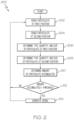
- FIG. 2 One embodiment of a process for determining particulate accumulation in the gas turbine engine 102 that the system 100 implements is depicted, in flowchart form, in FIG. 2 , and will now be described. Before proceeding, it is noted that the depicted process 200 is when the system 100 includes only two particulate sensors 134 (e.g., the first and second particulate sensors), but could readily be expanded for a system that includes three or more sensors 134.
- the process begins by sensing particulate at a first position on the gas turbine engine and supplying a first sensor signal representative thereof (202), and sensing particulate at a second position on the gas turbine engine and supplying a second sensor signal representative thereof (204).
- the first position is located at a first side of a gas turbine engine component
- the second position is located at a second side of the gas turbine engine component and downstream of the first position.
- the first sensor signal is processed to determine the type, quantity, and size of the particulate at the first position (206)
- the second sensor signal is processed to determine type, quantity, and size of the particulate at the second position (208).
- the amount of particulate accumulated on the gas turbine engine component is then determined (210). As previously noted, this determination is based at least on the quantity and size of particulate at the first and the second positions.
- the amount of particulate accumulated on the gas turbine engine component is then compared to a threshold value (212). If the amount exceeds the threshold value, then an alert is generated (214). If not, then the process 200 repeats. Though not depicted in FIG. 2 , it will be appreciated that the process 200 may be further expanded to include, for example, communicating the type of particulate accumulated on the gas turbine engine component, and/or initiating one or more mitigation or corrective actions.
- the systems and methods described herein differentiate between different types, quantities, and sizes of particulate at various locations within a gas turbine engine, which allows determining if, and how much, particulate is accumulating at various locations on or within the engine.
- a gas turbine engine particulate ingestion detection system includes a first particulate sensor, a second particulate sensor, and a processor.
- the first particulate sensor is mounted at a first position on the gas turbine engine, where the first position is located upstream of a gas turbine engine component.
- the first particulate sensor is configured to sense particulate at the first position and supply a first sensor signal representative thereof.
- the second particulate sensor is mounted at a second position on the gas turbine engine, where the second position is located downstream of the gas turbine engine component and downstream of the first position.
- the second particulate sensor is configured to sense particulate at the second position and supply a second sensor signal representative thereof.
- the processor is coupled to receive the first sensor signal and the second sensor signal.
- the processor is configured, upon receipt of the first and second sensors signal, to: (i) determine the type, quantity, and size of the particulate at the first position, (ii) determine the type, quantity, and size of the particulate at the second position, and (iii) determine, based at least on the quantity and size of the particulate at the first and second positions, an amount of particulate accumulated on the gas turbine engine component.
- the processor may be further configured to compare the amount of the particulate accumulated on the gas turbine engine component to a threshold value, and generate a signal when the amount exceeds the threshold value.
- the threshold value may depend on one or more of: the one or more types of particulate being sensed, the type of engine, and the particular engine component.
- An alert generator may coupled to receive the signal from the processor and configured, upon receipt of the signal, to generate an alert.
- the alert may communicate the type of particulate accumulated on the gas turbine engine component.
- the signal may initiate one or more actions to prevent or mitigate further particulate accumulation.
- the one or more actions may include one or more of: increasing the rotational speed of one or more gas turbine engine components; varying positons of one or more variable geometry devices; energizing one or more heaters; opening one or more compressor bypass channels; and displaying one or more messages to exit a source of the particulate.
- the particulate may comprise one or more of super-cooled water droplets, ice crystals, dust, and volcanic ash.
- the first and second sensors may each be selected from the group consisting of an optical sensor, a capacitive sensor, an electrostatic sensor, a lidar sensor, and a backscatter sensor.
- the system may further include a plurality of additional particulate sensors, where each additional particulate sensor is mounted at different positions on the gas turbine engine that are each different from the first and second positions, and each additional particulate sensor is configured to sense particulate at its position and supply an additional sensor signal representative thereof, and the processor may be further coupled to receive each of the additional sensor signals, and further configured, upon receipt of the additional sensors signal, to: determine type, quantity, and size of particulate at the different positions, and determine, based at least on the quantity and size of particulate at each of the different positions, an amount of the particulate accumulated on one or more additional gas turbine engine components.
- T he first turbine engine component may be a fan, and the additional turbine engine components may include a first compressor stage and a second compressor stage.
- a method for determining particulate accumulation in a gas turbine engine includes sensing particulate at a first position on the gas turbine engine and supplying a first sensor signal representative thereof, where the first position is located upstream of a gas turbine engine component, and sensing particulate at a second position on the gas turbine engine and supplying a second sensor signal representative thereof, where the second position is located downstream of the gas turbine engine component and downstream of the first position.
- the first sensor signal is processed to determine the type, quantity, and size of the particulate at the first position
- the second sensor signal is processed to determine the type, quantity, and size of the particulate at the second position. Based at least on the quantity and size of the particulate at the first and the second positions, an amount of the particulate accumulated on the gas turbine engine component is determined.
- aspects and other embodiments may include one or more of the following features. Comparing the amount of the particulate accumulated on the gas turbine engine component to a threshold value, and generating an alert when the amount exceeds the threshold value.
- the threshold value may depend on one or more of: the one or more types of particulate being sensed, the type of engine, and the particular engine component.
- the alert may communicate the type of particulate accumulated on the gas turbine engine component.
- One or more actions to prevent or mitigate further particulate accumulation may be initiated.
- the one or more actions may include one or more of: increasing the rotational speed of one or more gas turbine engine components; varying positons of one or more variable geometry devices; energizing one or more heaters; opening one or more compressor bypass channels; and displaying one or more messages to exit a source of the particulate.
- the particulate may comprise one or more of super-cooled water droplets, ice crystals, dust, and volcanic ash. Sensing particulate at a plurality of positions in the gas turbine engine that are each different from the first and second positions, and supplying a plurality of additional sensor signals.
- a gas turbine engine particulate ingestion detection system wherein the particulate is one or both of super cooled liquid droplets and frozen ice particles, includes a first particulate sensor, a second particulate sensor, and a processor.
- the first particulate sensor is mounted at a first position on the gas turbine engine, where the first position located at a first side upstream of a gas turbine engine component.
- the first particulate sensor is configured to sense particulate at the first position and supply a first sensor signal representative thereof.
- the second particulate sensor is mounted at a second position on the gas turbine engine, where the second position located downstream of the gas turbine engine component and downstream of the first position.
- the second particulate sensor is configured to sense particulate at the second position and supply a second sensor signal representative thereof.
- the processor is coupled to receive the first sensor signal and the second sensor signal, and is configured, upon receipt of the first and second sensors signal, to: (i) determine the type, quantity, and size of the particulate at the first position, (ii) determine the type, quantity, and size of the particulate at the second position, (iii) determine, based at least on the quantity and size of the particulate at the first and second positions, an amount of ice accreted on the gas turbine engine component, (iv) compare the amount of ice accreted on the gas turbine engine component to a threshold value, and (v) generate a signal when the amount exceeds the threshold value.
- Skilled artisans may implement the described functionality in varying ways for each particular application, but such implementation decisions should not be interpreted as causing a departure from the scope of the present invention.
- an embodiment of a system or a component may employ various integrated circuit components, e.g., memory elements, digital signal processing elements, logic elements, look-up tables, or the like, which may carry out a variety of functions under the control of one or more microprocessors or other control devices.
- integrated circuit components e.g., memory elements, digital signal processing elements, logic elements, look-up tables, or the like, which may carry out a variety of functions under the control of one or more microprocessors or other control devices.
- DSP digital signal processor
- ASIC application specific integrated circuit
- FPGA field programmable gate array
- a general-purpose processor may be a microprocessor, but in the alternative, the processor may be any conventional processor, controller, microcontroller, or state machine.
- a processor may also be implemented as a combination of computing devices, e.g., a combination of a DSP and a microprocessor, a plurality of microprocessors, one or more microprocessors in conjunction with a DSP core, or any other such configuration.
- a software module may reside in RAM memory, flash memory, ROM memory, EPROM memory, EEPROM memory, registers, hard disk, a removable disk, a CD-ROM, or any other form of storage medium known in the art.
- An exemplary storage medium is coupled to the processor such that the processor can read information from, and write information to, the storage medium.
- the storage medium may be integral to the processor.
- the processor and the storage medium may reside in an ASIC.
- an embodiment of a system or a component may employ various integrated circuit components, e.g., memory elements, digital signal processing elements, logic elements, look-up tables, or the like, which may carry out a variety of functions under the control of one or more microprocessors or other control devices.
- integrated circuit components e.g., memory elements, digital signal processing elements, logic elements, look-up tables, or the like, which may carry out a variety of functions under the control of one or more microprocessors or other control devices.
- various elements of the systems described herein are essentially the code segments or instructions that perform the various tasks.
- the program or code segments can be stored in a processor-readable medium or transmitted by a computer data signal embodied in a carrier wave over a transmission medium or communication path.
- the "computer-readable medium”, “processor-readable medium”, or “machine-readable medium” may include any medium that can store or transfer information. Examples of the processor-readable medium include an electronic circuit, a semiconductor memory device, a ROM, a flash memory, an erasable ROM (EROM), a floppy diskette, a CD-ROM, an optical disk, a hard disk, a fiber optic medium, a radio frequency (RF) link, or the like.
- RF radio frequency
- the computer data signal may include any signal that can propagate over a transmission medium such as electronic network channels, optical fibers, air, electromagnetic paths, or RF links.
- the code segments may be downloaded via computer networks such as the Internet, an intranet, a LAN, or the like.
Landscapes
- Engineering & Computer Science (AREA)
- Mechanical Engineering (AREA)
- General Engineering & Computer Science (AREA)
- Chemical & Material Sciences (AREA)
- Combustion & Propulsion (AREA)
- Supercharger (AREA)
- Output Control And Ontrol Of Special Type Engine (AREA)
Claims (7)
- Système de détection d'ingestion de particules de moteur à turbine à gaz (100), dans lequel les particules sont des particules de glace gelées, comprenant :un premier capteur de particules (134-1) monté au niveau d'une première position sur le moteur à turbine à gaz (102), la première position étant située en amont d'un composant de moteur à turbine à gaz (118), le premier capteur de particules étant configuré pour détecter des particules de glace au niveau de la première position et fournir un premier signal de capteur représentatif de celles-ci ;un deuxième capteur de particules (134-2) monté au niveau d'une deuxième position sur le moteur à turbine à gaz, la deuxième position étant située en aval du composant de moteur à turbine à gaz (118) et de la première position, le deuxième capteur de particules étant configuré pour détecter des particules de glace au niveau de la seconde position et fournir un deuxième signal de capteur représentatif de celles-ci ; etun processeur (136) couplé pour recevoir le premier signal de capteur et le deuxième signal de capteur, le processeur étant configuré, lors de la réception du premier et du deuxième signal de capteur, pour :déterminer la quantité et la taille des particules de glace au niveau de la première position ;déterminer la quantité et la taille des particules de glace au niveau de la deuxième position ;déterminer, sur la base au moins de la quantité et de la taille des particules de glace au niveau des première et deuxième positions, une quantité de glace accumulée sur le composant de moteur à turbine à gaz ;comparer (212) la quantité de glace accumulée sur le composant de moteur à turbine à gaz à une valeur seuil ; etgénérer (214) un signal lorsque la quantité dépasse la valeur seuil ;dans lequel le composant de moteur à turbine à gaz est une soufflante (118) ; etdans lequel les premier et deuxième capteurs sont chacun des capteurs optiques.
- Système selon la revendication 1, comprenant en outre :
un générateur d'alerte (140) couplé pour recevoir le signal du processeur et configuré, lors de la réception du signal, pour générer une alerte. - Système selon la revendication 1, dans lequel le signal lance une ou plusieurs actions pour empêcher ou atténuer une accumulation supplémentaire de particules.
- Système selon la revendication 3, dans lequel les une ou plusieurs actions incluent un ou plusieurs parmi :l'augmentation de la vitesse de rotation d'un ou plusieurs composants de moteur à turbine à gaz ;la variation de positions d'un ou plusieurs dispositifs à géométrie variable ;l'excitation d'un ou plusieurs éléments chauffants ;l'ouverture d'un ou plusieurs canaux de dérivation de compresseur ; etl'affichage d'un ou plusieurs messages pour quitter une source des particules.
- Système selon la revendication 1, comprenant en outre :une pluralité de capteurs de particules supplémentaires (134-3, 134-4, 134-5), chaque capteur de particules supplémentaire étant monté au niveau de différentes positions sur le moteur à turbine à gaz qui sont chacune différentes des première et deuxième positions, chaque capteur de particules supplémentaire étant configuré pour détecter des particules de glace au niveau de sa position et fournir un signal de capteur supplémentaire représentatif de celles-ci,dans lequel le processeur est en outre couplé pour recevoir chacun des signaux de capteurs supplémentaires, et est en outre configuré, lors de la réception du signal de capteurs supplémentaire, pour :déterminer la quantité et la taille des particules de glace au niveau des différentes positions, etdéterminer, sur la base au moins de la quantité et de la taille des particules de glace au niveau de chacune des différentes positions, une quantité des particules de glace accumulée sur un ou plusieurs composants de moteur à turbine à gaz supplémentaires.
- Système selon la revendication 5, dans lequel :
les composants de moteur à turbine supplémentaires incluent un premier étage de compresseur et un deuxième étage de compresseur. - Procédé (200) pour déterminer l'accumulation de particules dans un moteur à turbine à gaz (102), dans lequel les particules sont des particules de glace gelées, le procédé comprenant les étapes suivantes :la détection (202) de particules de glace au niveau d'une première position sur le moteur à turbine à gaz et la fourniture d'un premier signal de capteur représentatif de celles-ci, la première position étant située en amont d'un composant de moteur à turbine à gaz ;la détection (204) de particules de glace au niveau d'une deuxième position sur le moteur à turbine à gaz et la fourniture d'un deuxième signal de capteur représentatif de celles-ci, la deuxième position étant située en aval du composant de moteur à turbine à gaz et de la première position ;le traitement du premier signal de capteur pour déterminer (206) la quantité et la taille des particules de glace au niveau de la première position ;le traitement du deuxième signal de capteur pour déterminer (208) la quantité et la taille des particules de glace au niveau de la deuxième position ;la détermination (210), sur la base au moins de la quantité et de la taille des particules de glace au niveau des première et deuxième positions, d'une quantité de la glace accumulée sur le composant de moteur à turbine à gaz ;la comparaison (212) de la quantité de glace accumulée sur le composant de moteur à turbine à gaz à une valeur seuil ; etla génération (214) d'un signal lorsque la quantité dépasse la valeur seuil ;dans lequel les premier et deuxième capteurs sont chacun des capteurs optiques ; etdans lequel le composant de moteur à turbine à gaz est une soufflante (118).
Applications Claiming Priority (1)
| Application Number | Priority Date | Filing Date | Title |
|---|---|---|---|
| US15/490,029 US20180298778A1 (en) | 2017-04-18 | 2017-04-18 | Gas turbine engine particulate ingestion and accumulation sensor system and method |
Publications (2)
| Publication Number | Publication Date |
|---|---|
| EP3392467A1 EP3392467A1 (fr) | 2018-10-24 |
| EP3392467B1 true EP3392467B1 (fr) | 2024-11-06 |
Family
ID=62002046
Family Applications (1)
| Application Number | Title | Priority Date | Filing Date |
|---|---|---|---|
| EP18167394.8A Active EP3392467B1 (fr) | 2017-04-18 | 2018-04-13 | Système de détection d'ingestion de particules de moteur de turbine a gaz et procédé associé |
Country Status (2)
| Country | Link |
|---|---|
| US (2) | US20180298778A1 (fr) |
| EP (1) | EP3392467B1 (fr) |
Families Citing this family (8)
| Publication number | Priority date | Publication date | Assignee | Title |
|---|---|---|---|---|
| US11149583B2 (en) * | 2017-04-18 | 2021-10-19 | Honeywell International Inc. | Gas turbine engine particulate ingestion and accumulation sensor system and method |
| GB201820301D0 (en) * | 2018-12-13 | 2019-01-30 | Rolls Royce Plc | Water and ice detection |
| US10845294B1 (en) | 2019-07-03 | 2020-11-24 | Raytheon Technologies Corporation | Systems and methods for particulate ingestion sensing in gas turbine engines |
| US11492967B2 (en) | 2019-07-03 | 2022-11-08 | Raytheon Technologies Corporation | Particulate ingestion sensor for gas turbine engines |
| US11840933B2 (en) | 2019-12-13 | 2023-12-12 | Rtx Corporation | LiDAR based FOD detection for gas-turbine engines |
| EP3889395B1 (fr) * | 2020-03-30 | 2024-02-28 | Honeywell International Inc. | Système et procédé de capteur d'ingestion et d'accumulation de particules de moteur de turbine à gaz |
| US12196658B2 (en) | 2020-12-01 | 2025-01-14 | Rtx Corporation | Optical particulate detection for an aircraft |
| US11726035B2 (en) * | 2020-12-11 | 2023-08-15 | Raytheon Technologies Corporation | Terahertz enhanced foreign object debris discrimination for optical particulate sensor |
Citations (2)
| Publication number | Priority date | Publication date | Assignee | Title |
|---|---|---|---|---|
| WO2015034513A1 (fr) * | 2013-09-06 | 2015-03-12 | Ge Aviation Systems Llc | Avion, et procédé de détection de particules |
| EP3061691A1 (fr) * | 2015-02-24 | 2016-08-31 | General Electric Company | Système antigivrage de turbine à gaz assistée par imagerie |
Family Cites Families (5)
| Publication number | Priority date | Publication date | Assignee | Title |
|---|---|---|---|---|
| GB8707187D0 (en) * | 1987-03-25 | 1987-04-29 | Hughes Ltd Stewart | Monitoring of foreign object in engines |
| US8074498B2 (en) * | 2009-05-18 | 2011-12-13 | United Technologies Corporation | System and method of assessing thermal energy levels of a gas turbine engine component |
| GB0917319D0 (en) * | 2009-10-05 | 2009-11-18 | Rolls Royce Plc | An apparatus and method of operating a gas turbine engine |
| US8459103B2 (en) * | 2011-06-24 | 2013-06-11 | United Technologies Corporation | IDMS signal processing to distinguish inlet particulates |
| US9776731B1 (en) * | 2016-09-29 | 2017-10-03 | The Boeing Company | Methods and apparatus for detecting aircraft surface deformations |
-
2017
- 2017-04-18 US US15/490,029 patent/US20180298778A1/en not_active Abandoned
-
2018
- 2018-04-13 EP EP18167394.8A patent/EP3392467B1/fr active Active
-
2019
- 2019-09-09 US US16/564,617 patent/US20200018180A1/en not_active Abandoned
Patent Citations (2)
| Publication number | Priority date | Publication date | Assignee | Title |
|---|---|---|---|---|
| WO2015034513A1 (fr) * | 2013-09-06 | 2015-03-12 | Ge Aviation Systems Llc | Avion, et procédé de détection de particules |
| EP3061691A1 (fr) * | 2015-02-24 | 2016-08-31 | General Electric Company | Système antigivrage de turbine à gaz assistée par imagerie |
Also Published As
| Publication number | Publication date |
|---|---|
| US20180298778A1 (en) | 2018-10-18 |
| US20200018180A1 (en) | 2020-01-16 |
| EP3392467A1 (fr) | 2018-10-24 |
Similar Documents
| Publication | Publication Date | Title |
|---|---|---|
| EP3392467B1 (fr) | Système de détection d'ingestion de particules de moteur de turbine a gaz et procédé associé | |
| US11149583B2 (en) | Gas turbine engine particulate ingestion and accumulation sensor system and method | |
| Rath et al. | Aero engine health monitoring, diagnostics and prognostics for condition-based maintenance: An overview | |
| Lakshminarasimha et al. | Modeling and analysis of gas turbine performance deterioration | |
| US9133773B2 (en) | Method and controller for detecting ice | |
| EP3039270B1 (fr) | Détection de l'extinction d'une turbine à gaz | |
| US10496086B2 (en) | Gas turbine engine fleet performance deterioration | |
| US8869603B2 (en) | Debris detection in turbomachinery and gas turbine engines | |
| EP3889395B1 (fr) | Système et procédé de capteur d'ingestion et d'accumulation de particules de moteur de turbine à gaz | |
| EP3865695B1 (fr) | Stratégies de détection et d'atténuation d'inversion de température pour éviter la surtension du compresseur | |
| EP3139143B1 (fr) | Système et procédé de détermination d'une température d'air totale à partir de la température d'écoulement de dérivation à double flux | |
| US20180306052A1 (en) | Fluid supply line leakage detection system and method | |
| EP2835517B1 (fr) | Système empêcher l'accumulation de cristaux de glace dans des moteurs à turbine à gaz | |
| Veres et al. | Modeling of commercial turbofan engine with ice crystal ingestion; follow-on | |
| CN116620555A (zh) | 用于提供关于飞行器发动机内的颗粒物的信息的系统和方法 | |
| EP3106649A1 (fr) | Commande de moteur de propulsion d'avion à turbine à gaz sans capteurs de température d'air totale d'aéronef | |
| EP3561388B1 (fr) | Système et procédé de surveillance de colmatage de sable dans des moteurs à turbine à gaz | |
| Jorgenson et al. | Modeling the deterioration of engine and low pressure compressor performance during a rollback event due to ice accretion | |
| Lakshminarasimha et al. | Modelling and analysis of gas turbine performance deterioration | |
| Koh et al. | A computational study to investigate the effect of altitude on deteriorated engine performance | |
| Bin et al. | Icing certification of civil aircraft engines | |
| Mishra et al. | Analysis of compressor surge in a military turbojet engine: a case study | |
| US12188410B2 (en) | Icing condition identification for gas turbine engine | |
| Jorgenson et al. | Modeling of Commercial Turbofan Engine With Ice Crystal Ingestion: Follow-On | |
| US20230212956A1 (en) | System and method to increase the temperature of oil used to anti-ice a gas turbine propulsion engine |
Legal Events
| Date | Code | Title | Description |
|---|---|---|---|
| PUAI | Public reference made under article 153(3) epc to a published international application that has entered the european phase |
Free format text: ORIGINAL CODE: 0009012 |
|
| STAA | Information on the status of an ep patent application or granted ep patent |
Free format text: STATUS: REQUEST FOR EXAMINATION WAS MADE |
|
| 17P | Request for examination filed |
Effective date: 20180413 |
|
| AK | Designated contracting states |
Kind code of ref document: A1 Designated state(s): AL AT BE BG CH CY CZ DE DK EE ES FI FR GB GR HR HU IE IS IT LI LT LU LV MC MK MT NL NO PL PT RO RS SE SI SK SM TR |
|
| AX | Request for extension of the european patent |
Extension state: BA ME |
|
| STAA | Information on the status of an ep patent application or granted ep patent |
Free format text: STATUS: EXAMINATION IS IN PROGRESS |
|
| 17Q | First examination report despatched |
Effective date: 20190918 |
|
| RAP3 | Party data changed (applicant data changed or rights of an application transferred) |
Owner name: HONEYWELL INTERNATIONAL INC. |
|
| P01 | Opt-out of the competence of the unified patent court (upc) registered |
Effective date: 20230421 |
|
| GRAP | Despatch of communication of intention to grant a patent |
Free format text: ORIGINAL CODE: EPIDOSNIGR1 |
|
| STAA | Information on the status of an ep patent application or granted ep patent |
Free format text: STATUS: GRANT OF PATENT IS INTENDED |
|
| INTG | Intention to grant announced |
Effective date: 20240604 |
|
| GRAS | Grant fee paid |
Free format text: ORIGINAL CODE: EPIDOSNIGR3 |
|
| GRAA | (expected) grant |
Free format text: ORIGINAL CODE: 0009210 |
|
| STAA | Information on the status of an ep patent application or granted ep patent |
Free format text: STATUS: THE PATENT HAS BEEN GRANTED |
|
| AK | Designated contracting states |
Kind code of ref document: B1 Designated state(s): AL AT BE BG CH CY CZ DE DK EE ES FI FR GB GR HR HU IE IS IT LI LT LU LV MC MK MT NL NO PL PT RO RS SE SI SK SM TR |
|
| REG | Reference to a national code |
Ref country code: GB Ref legal event code: FG4D |
|
| REG | Reference to a national code |
Ref country code: CH Ref legal event code: EP |
|
| REG | Reference to a national code |
Ref country code: DE Ref legal event code: R096 Ref document number: 602018076189 Country of ref document: DE |
|
| REG | Reference to a national code |
Ref country code: IE Ref legal event code: FG4D |
|
| REG | Reference to a national code |
Ref country code: LT Ref legal event code: MG9D |
|
| REG | Reference to a national code |
Ref country code: NL Ref legal event code: MP Effective date: 20241106 |
|
| PG25 | Lapsed in a contracting state [announced via postgrant information from national office to epo] |
Ref country code: PT Free format text: LAPSE BECAUSE OF FAILURE TO SUBMIT A TRANSLATION OF THE DESCRIPTION OR TO PAY THE FEE WITHIN THE PRESCRIBED TIME-LIMIT Effective date: 20250306 Ref country code: HR Free format text: LAPSE BECAUSE OF FAILURE TO SUBMIT A TRANSLATION OF THE DESCRIPTION OR TO PAY THE FEE WITHIN THE PRESCRIBED TIME-LIMIT Effective date: 20241106 Ref country code: IS Free format text: LAPSE BECAUSE OF FAILURE TO SUBMIT A TRANSLATION OF THE DESCRIPTION OR TO PAY THE FEE WITHIN THE PRESCRIBED TIME-LIMIT Effective date: 20250306 |
|
| PG25 | Lapsed in a contracting state [announced via postgrant information from national office to epo] |
Ref country code: FI Free format text: LAPSE BECAUSE OF FAILURE TO SUBMIT A TRANSLATION OF THE DESCRIPTION OR TO PAY THE FEE WITHIN THE PRESCRIBED TIME-LIMIT Effective date: 20241106 Ref country code: NL Free format text: LAPSE BECAUSE OF FAILURE TO SUBMIT A TRANSLATION OF THE DESCRIPTION OR TO PAY THE FEE WITHIN THE PRESCRIBED TIME-LIMIT Effective date: 20241106 |
|
| REG | Reference to a national code |
Ref country code: AT Ref legal event code: MK05 Ref document number: 1739556 Country of ref document: AT Kind code of ref document: T Effective date: 20241106 |
|
| PG25 | Lapsed in a contracting state [announced via postgrant information from national office to epo] |
Ref country code: BG Free format text: LAPSE BECAUSE OF FAILURE TO SUBMIT A TRANSLATION OF THE DESCRIPTION OR TO PAY THE FEE WITHIN THE PRESCRIBED TIME-LIMIT Effective date: 20241106 |
|
| PG25 | Lapsed in a contracting state [announced via postgrant information from national office to epo] |
Ref country code: ES Free format text: LAPSE BECAUSE OF FAILURE TO SUBMIT A TRANSLATION OF THE DESCRIPTION OR TO PAY THE FEE WITHIN THE PRESCRIBED TIME-LIMIT Effective date: 20241106 |
|
| PG25 | Lapsed in a contracting state [announced via postgrant information from national office to epo] |
Ref country code: NO Free format text: LAPSE BECAUSE OF FAILURE TO SUBMIT A TRANSLATION OF THE DESCRIPTION OR TO PAY THE FEE WITHIN THE PRESCRIBED TIME-LIMIT Effective date: 20250206 |
|
| PG25 | Lapsed in a contracting state [announced via postgrant information from national office to epo] |
Ref country code: LV Free format text: LAPSE BECAUSE OF FAILURE TO SUBMIT A TRANSLATION OF THE DESCRIPTION OR TO PAY THE FEE WITHIN THE PRESCRIBED TIME-LIMIT Effective date: 20241106 Ref country code: GR Free format text: LAPSE BECAUSE OF FAILURE TO SUBMIT A TRANSLATION OF THE DESCRIPTION OR TO PAY THE FEE WITHIN THE PRESCRIBED TIME-LIMIT Effective date: 20250207 Ref country code: AT Free format text: LAPSE BECAUSE OF FAILURE TO SUBMIT A TRANSLATION OF THE DESCRIPTION OR TO PAY THE FEE WITHIN THE PRESCRIBED TIME-LIMIT Effective date: 20241106 |
|
| PG25 | Lapsed in a contracting state [announced via postgrant information from national office to epo] |
Ref country code: PL Free format text: LAPSE BECAUSE OF FAILURE TO SUBMIT A TRANSLATION OF THE DESCRIPTION OR TO PAY THE FEE WITHIN THE PRESCRIBED TIME-LIMIT Effective date: 20241106 |
|
| PG25 | Lapsed in a contracting state [announced via postgrant information from national office to epo] |
Ref country code: RS Free format text: LAPSE BECAUSE OF FAILURE TO SUBMIT A TRANSLATION OF THE DESCRIPTION OR TO PAY THE FEE WITHIN THE PRESCRIBED TIME-LIMIT Effective date: 20250206 |
|
| PG25 | Lapsed in a contracting state [announced via postgrant information from national office to epo] |
Ref country code: SM Free format text: LAPSE BECAUSE OF FAILURE TO SUBMIT A TRANSLATION OF THE DESCRIPTION OR TO PAY THE FEE WITHIN THE PRESCRIBED TIME-LIMIT Effective date: 20241106 |
|
| PGFP | Annual fee paid to national office [announced via postgrant information from national office to epo] |
Ref country code: DE Payment date: 20250428 Year of fee payment: 8 |
|
| PG25 | Lapsed in a contracting state [announced via postgrant information from national office to epo] |
Ref country code: DK Free format text: LAPSE BECAUSE OF FAILURE TO SUBMIT A TRANSLATION OF THE DESCRIPTION OR TO PAY THE FEE WITHIN THE PRESCRIBED TIME-LIMIT Effective date: 20241106 |
|
| PG25 | Lapsed in a contracting state [announced via postgrant information from national office to epo] |
Ref country code: EE Free format text: LAPSE BECAUSE OF FAILURE TO SUBMIT A TRANSLATION OF THE DESCRIPTION OR TO PAY THE FEE WITHIN THE PRESCRIBED TIME-LIMIT Effective date: 20241106 |
|
| PG25 | Lapsed in a contracting state [announced via postgrant information from national office to epo] |
Ref country code: RO Free format text: LAPSE BECAUSE OF FAILURE TO SUBMIT A TRANSLATION OF THE DESCRIPTION OR TO PAY THE FEE WITHIN THE PRESCRIBED TIME-LIMIT Effective date: 20241106 |
|
| PG25 | Lapsed in a contracting state [announced via postgrant information from national office to epo] |
Ref country code: SK Free format text: LAPSE BECAUSE OF FAILURE TO SUBMIT A TRANSLATION OF THE DESCRIPTION OR TO PAY THE FEE WITHIN THE PRESCRIBED TIME-LIMIT Effective date: 20241106 |
|
| PG25 | Lapsed in a contracting state [announced via postgrant information from national office to epo] |
Ref country code: CZ Free format text: LAPSE BECAUSE OF FAILURE TO SUBMIT A TRANSLATION OF THE DESCRIPTION OR TO PAY THE FEE WITHIN THE PRESCRIBED TIME-LIMIT Effective date: 20241106 |
|
| PG25 | Lapsed in a contracting state [announced via postgrant information from national office to epo] |
Ref country code: IT Free format text: LAPSE BECAUSE OF FAILURE TO SUBMIT A TRANSLATION OF THE DESCRIPTION OR TO PAY THE FEE WITHIN THE PRESCRIBED TIME-LIMIT Effective date: 20241106 |
|
| REG | Reference to a national code |
Ref country code: DE Ref legal event code: R097 Ref document number: 602018076189 Country of ref document: DE |
|
| PG25 | Lapsed in a contracting state [announced via postgrant information from national office to epo] |
Ref country code: SE Free format text: LAPSE BECAUSE OF FAILURE TO SUBMIT A TRANSLATION OF THE DESCRIPTION OR TO PAY THE FEE WITHIN THE PRESCRIBED TIME-LIMIT Effective date: 20241106 |
|
| PLBE | No opposition filed within time limit |
Free format text: ORIGINAL CODE: 0009261 |
|
| STAA | Information on the status of an ep patent application or granted ep patent |
Free format text: STATUS: NO OPPOSITION FILED WITHIN TIME LIMIT |
|
| 26N | No opposition filed |
Effective date: 20250807 |
|
| REG | Reference to a national code |
Ref country code: CH Ref legal event code: H13 Free format text: ST27 STATUS EVENT CODE: U-0-0-H10-H13 (AS PROVIDED BY THE NATIONAL OFFICE) Effective date: 20251125 |
|
| PG25 | Lapsed in a contracting state [announced via postgrant information from national office to epo] |
Ref country code: LU Free format text: LAPSE BECAUSE OF NON-PAYMENT OF DUE FEES Effective date: 20250413 |
|
| PG25 | Lapsed in a contracting state [announced via postgrant information from national office to epo] |
Ref country code: MC Free format text: LAPSE BECAUSE OF FAILURE TO SUBMIT A TRANSLATION OF THE DESCRIPTION OR TO PAY THE FEE WITHIN THE PRESCRIBED TIME-LIMIT Effective date: 20241106 |
|
| GBPC | Gb: european patent ceased through non-payment of renewal fee |
Effective date: 20250413 |
|
| REG | Reference to a national code |
Ref country code: BE Ref legal event code: MM Effective date: 20250430 |
|
| PG25 | Lapsed in a contracting state [announced via postgrant information from national office to epo] |
Ref country code: GB Free format text: LAPSE BECAUSE OF NON-PAYMENT OF DUE FEES Effective date: 20250413 |
|
| PG25 | Lapsed in a contracting state [announced via postgrant information from national office to epo] |
Ref country code: FR Free format text: LAPSE BECAUSE OF NON-PAYMENT OF DUE FEES Effective date: 20250430 |
|
| PG25 | Lapsed in a contracting state [announced via postgrant information from national office to epo] |
Ref country code: BE Free format text: LAPSE BECAUSE OF NON-PAYMENT OF DUE FEES Effective date: 20250430 |
|
| PG25 | Lapsed in a contracting state [announced via postgrant information from national office to epo] |
Ref country code: CH Free format text: LAPSE BECAUSE OF NON-PAYMENT OF DUE FEES Effective date: 20250430 |