EP3392123A1 - Front cabin frame assembly - Google Patents
Front cabin frame assembly Download PDFInfo
- Publication number
- EP3392123A1 EP3392123A1 EP16874573.5A EP16874573A EP3392123A1 EP 3392123 A1 EP3392123 A1 EP 3392123A1 EP 16874573 A EP16874573 A EP 16874573A EP 3392123 A1 EP3392123 A1 EP 3392123A1
- Authority
- EP
- European Patent Office
- Prior art keywords
- frame assembly
- cabin frame
- section
- upper side
- pillar
- Prior art date
- Legal status (The legal status is an assumption and is not a legal conclusion. Google has not performed a legal analysis and makes no representation as to the accuracy of the status listed.)
- Granted
Links
Images


Classifications
-
- B—PERFORMING OPERATIONS; TRANSPORTING
- B62—LAND VEHICLES FOR TRAVELLING OTHERWISE THAN ON RAILS
- B62D—MOTOR VEHICLES; TRAILERS
- B62D25/00—Superstructure or monocoque structure sub-units; Parts or details thereof not otherwise provided for
- B62D25/08—Front or rear portions
- B62D25/082—Engine compartments
-
- B—PERFORMING OPERATIONS; TRANSPORTING
- B60—VEHICLES IN GENERAL
- B60R—VEHICLES, VEHICLE FITTINGS, OR VEHICLE PARTS, NOT OTHERWISE PROVIDED FOR
- B60R19/00—Wheel guards; Radiator guards, e.g. grilles; Obstruction removers; Fittings damping bouncing force in collisions
- B60R19/02—Bumpers, i.e. impact receiving or absorbing members for protecting vehicles or fending off blows from other vehicles or objects
- B60R19/24—Arrangements for mounting bumpers on vehicles
- B60R19/26—Arrangements for mounting bumpers on vehicles comprising yieldable mounting means
- B60R19/34—Arrangements for mounting bumpers on vehicles comprising yieldable mounting means destroyed upon impact, e.g. one-shot type
-
- B—PERFORMING OPERATIONS; TRANSPORTING
- B62—LAND VEHICLES FOR TRAVELLING OTHERWISE THAN ON RAILS
- B62D—MOTOR VEHICLES; TRAILERS
- B62D21/00—Understructures, i.e. chassis frame on which a vehicle body may be mounted
- B62D21/15—Understructures, i.e. chassis frame on which a vehicle body may be mounted having impact absorbing means, e.g. a frame designed to permanently or temporarily change shape or dimension upon impact with another body
- B62D21/152—Front or rear frames
-
- B—PERFORMING OPERATIONS; TRANSPORTING
- B62—LAND VEHICLES FOR TRAVELLING OTHERWISE THAN ON RAILS
- B62D—MOTOR VEHICLES; TRAILERS
- B62D25/00—Superstructure or monocoque structure sub-units; Parts or details thereof not otherwise provided for
- B62D25/08—Front or rear portions
- B62D25/081—Cowls
-
- B—PERFORMING OPERATIONS; TRANSPORTING
- B62—LAND VEHICLES FOR TRAVELLING OTHERWISE THAN ON RAILS
- B62D—MOTOR VEHICLES; TRAILERS
- B62D25/00—Superstructure or monocoque structure sub-units; Parts or details thereof not otherwise provided for
- B62D25/20—Floors or bottom sub-units
- B62D25/2009—Floors or bottom sub-units in connection with other superstructure subunits
- B62D25/2018—Floors or bottom sub-units in connection with other superstructure subunits the subunits being front structures
Definitions
- the present invention relates to the field of vehicle body structure, and more particularly to a front cabin frame assembly.
- front cabin As main structure of a vehicle body to endure head-on collision, front cabin must have the ability of absorbing collision energy, distributing and transferring impact force effectively through reasonable deformation, so as to protect the passenger compartment. In addition, the front cabin should have sufficient flexural and torsional stiffness and good NVH (Noise, Vibration and Harshness) performance.
- NVH Noise, Vibration and Harshness
- the common front cabin frame is composed of front bumper, left and right front beams, front reinforcement structure and A-pillar.
- this structure does not have enough load transfer path and the load transfer path of this structure is insufficient and discontinuous.
- the front cabin will not be able to absorb and dissipate the collision energy effectively, result a large amount of invasion in the dash panel and a large amount of deformation of the floor and the middle channel, and further cause a great damage to the passengers in the passenger compartment and affect the collision safety of the entire vehicle.
- the flexural and torsional stiffness of the vehicle body is not good enough due to the structure does not have reasonable continuously connected structure. This is not benefit for the improvement of the vehicle NVH performance.
- the present invention provides a front cabin frame assembly which has reasonable load transfer path and could absorb and dissipate the collision energy effectively when subject to a head-on collision, and effectively increases the flexural and torsional stiffness of the entire vehicle and improves the collision safety and the vehicle NVH performance.
- the front cabin frame assembly of the present invention includes a front beam front section, an upper side beam, a cowl reinforcement crossbeam, a cowl outer reinforcement and an A-pillar.
- a front end of the front beam front section is laterally connected with a front end of the upper side beam.
- a root portion of the front beam front section is connected with the cowl reinforcement crossbeam.
- a root portion of the upper side beam is connected with the A-pillar.
- the cowl outer reinforcement is connected with the root portion of the front beam front section and the A-pillar.
- the front cabin frame assembly further includes an energy absorbing box disposed in the front of the front beam front section and a bumper beam disposed in the front of the energy absorbing box.
- the bumper beam, the energy absorbing box, the front beam front section and the cowl reinforcement crossbeam cooperatively form a frame having a shape of " ".
- the upper side beam is located at outer side of the front beam front section along a width direction of a vehicle body.
- the frontmost end of the upper side beam extends beyond a rear end of the energy absorbing box.
- the upper side beam includes a first portion, a second portion and a third portion.
- the first portion is connected with the front beam front section
- the third portion is connected with the A-pillar
- the second portion connects the first portion with the third portion and is configured in arc shape.
- a height of the first portion is lower than a height of the third portion.
- a front end of the second portion is connected with a front end of the front beam front section through a front headlamp crossbeam and a front module mounting pillar
- a front end of the first portion is connected with the front end of front beam front section through a front beam connection bracket.
- a height of the front end of the first portion is higher than a height of the front beam front section along a height direction of a vehicle body.
- the front cabin frame assembly further includes a drip rail and a front tower disposed between the front beam front section and the upper side beam.
- An upper portion of the front tower is connected with two opposite ends of the drip rail.
- the front beam connection bracket, the front tower, the front beam front section and the upper side beam cooperatively form a frame having a shape of " ".
- the frontmost of the first portion disposes a covering plate, and a lower part of a middle portion of the second portion disposes a plurality of energy absorbing ribs.
- a transverse area of the third portion gradually increases from an end connected with the second portion towards an end connected with the A-pillar.
- the third portion and the A-pillar connect to a continuously connected structure.
- the yield strength of the first portion, the second portion and the third portion increases gradually.
- the front cabin frame assembly further includes a front beam rear section, an outer connection bracket, an inner connection bracket and a middle channel side beam.
- the front beam rear section is connected with the root portion of the front beam front section
- the outer connection bracket is connected with the front beam rear section and the A-pillar
- the inner connection bracket is connected with the front beam rear section and the middle channel side beam.
- the front cabin frame assembly further includes a middle channel and a windshield crossbeam disposed above the cowl reinforcement crossbeam.
- the windshield crossbeam, the A-pillar, the cowl reinforcement crossbeam and the cowl outer reinforcement cooperatively form a frame having a shape of " ".
- a middle portion of the cowl reinforcement crossbeam is connected with the middle channel and the middle channel side beam to form a continuously connected structure.
- the front end of the upper side beam is connected with the front end of the front beam front section through the front beam connection bracket, the root portion of the front beam front section is connected with the cowl reinforcement crossbeam, the root portion of the upper side beam is connected with the A-pillar, thereby forming two longitudinal load transfer paths.
- the two longitudinal load transfer paths are designed to include a plurality of continuously connected overlapping crossbeams, thereby forming an enclosed ring-like front cabin frame. Therefore, the collision energy could be transferred along two paths and by the upper side beam and the front beam when the vehicle body is subject to a head-on collision.
- the collision energy is absorbed and transferred by a plurality of longitudinal beams and a plurality of lateral beams, which results the head-on collision energy be absorbed effectively and the load transfer path be more reasonable, thereby decreasing the deformation of the passenger compartment and the injury of the passengers, and increasing the collision safety of the entire vehicle.
- the enclosed ring-like front cabin frame includes a plurality of continuously connected overlapping beams along lateral and longitudinal directions, which improves the flexural and torsional stiffness of the vehicle body and further improves the NVH performance.
- the front cabin frame assembly of an embodiment of the present invention includes a bumper beam 10, two energy absorbing boxes 20, two front beam front sections 30, two upper side beams 40, two front beam connection brackets 50, two front headlamp crossbeams 60, two front module mounting pillars 70, a cowl reinforcement crossbeam 80, two cowl outer reinforcements 90, a front tower 100, two A-pillars 110, two front beam rear sections 120, two outer connection brackets 130, two inner connection brackets 140, a windshield crossbeam 150, a drip rail 160, a middle channel 170 and two middle channel side beams 180.
- the bumper beam 10 is disposed in front of the energy absorbing boxes 20, and the energy absorbing boxes 20 are disposed in front of the front beam front sections 30.
- the energy absorbing boxes 20 are disposed at two opposite ends of the bumper beam 10 and threadedly connected with front ends of the front beam front sections 30.
- the front beam front section 30 extends along a length direction (longitudinal direction) of the vehicle body, and the cowl reinforcement crossbeam 80 extends along a width direction (lateral direction) of the vehicle body. Two opposite ends of the cowl reinforcement crossbeam 80 are connected with root portions of the front beam front sections 30 respectively.
- This stable structure is capable of improving collision performance, the flexural and torsional stiffness and the NVH performance of the front cabin.
- the upper side beams 40 are disposed at outer sides of the front beam front sections 30 along the width direction of the vehicle body. Front ends of the upper side beams 40 are connected with the front ends of the front beam front sections 30 through the front beam connection brackets 50. Root portions of the upper side beams 40 are connected with the A-pillars 110.
- the front ends of the front beam front sections 30 are connected with the front ends of the upper side beams 40 through the front beam connection brackets 50, the root portions of the front beam front sections 30 are connected with the cowl reinforcement crossbeams 80, and the root portions of the upper side beams 40 are connected with the A-pillars 110, thereby providing two load transfer paths along the length direction of the vehicle body, that is to say, the impact force could be transferred along the front beam front section 30 and the upper side beam 40, and the collision energy could be absorbed and distributed effectively.
- the upper side beam 40 includes a first portion 41, a second portion 42 and a third portion 43.
- the first portion 41 is connected with the front end of the front beam front section 30, and the third portion 43 is connected with an upper portion of the A-pillar 110.
- a height of the first portion 41 is lower than a height of the third portion 43, this is because under the consideration of layout space requirement such as avoid the headlamp, the smaller the height difference between the first portion 41 and the third portion 43 is, the better the collision performance of the upper beam 40 is, due to the load transfer path along the upper side beam 40 is more straight.
- the second portion 42 connects the first portion 41 with the third portion 43 and is configured in arc shape.
- the arc-shaped configuration of the second portion 42 could avoid tire envelope and extend load absorb and transfer path, so that the upper side beam 40 could absorb and transfer the collision energy more effectively.
- the three portions of the upper side beam 40 could be arranged in different materials, for example, the first portion 41 and the second portion 42 are made of high-strength steel with a lower yield strength, while the third portion 43 is made of high-strength steel with a higher yield strength, thereby making the yield strength of the first portion 41, the second portion 42 and the third portion 43 increases gradually, and further making the entire structure of the upper side beam 40 be soft in front and hard in back, and weak in front and strong in back, so that the front portion of the upper side beam 40 could fully collapse and effectively absorb collision energy, making the rear portion of the upper side beam 40 could dissipate and transfer the rest of the collision energy effectively.
- the height of the front end of the first portion 41 is higher than a height of the front end of the front beam front section 30 along a height direction of the vehicle body. Moreover, the frontmost of the first portion 41, i.e., the frontmost of the upper side beam 40 extends beyond the rear end of the energy absorbing box 20 (i.e., the frontmost of the upper side beam 40 locates slightly in front of the rear end of the energy absorbing box 20).
- the obstacle could contact with the upper side beam 40 as it contacts with the front end of the front beam front section 30 in the case that the bumper beam 10 and the energy absorbing box 20 already collapsed and absorbed the collision energy effectively, so that the collision energy could be dissipated and transferred promptly and effectively.
- Due to the height of the front end of the first portion 41 is higher than the height of the front end of the front beam front section 30 along the height direction of the vehicle body, the collision energy could be transferred to the front end of the front beam 30 and the upper side beam 40, meanwhile, the height difference of two opposite ends of the upper side beam 40 is decreased, and a perfect energy absorb and transfer effect is obtained.
- a covering plate 411 is disposed at the frontmost of the first portion 41, which prevents the obstacle from invading in an inner compartment of the upper side beam 40 and reducing the energy absorb and transfer effect of the front end of the upper side beam 40.
- a plurality of energy absorbing ribs 421 are disposed at a lower part of a middle portion of the second portion 42 to benefit the first portion 41 and the second portion 42 of the upper side beam 40 to fully collapse and effectively absorb the collision energy, and decrease the impact of the rear portion of the upper side beam 40 (i.e., the third portion 43) on the A-pillar 110.
- a width of the upper side beam 40 substantially equals to a width of the A-pillar 110 along the width direction of the vehicle body, which prevents a curved structure being formed between the upper side beam 40 and the A-pillar 110, and further ensures the collision energy be transferred along a straight line.
- the front end of the first portion 41 is laterally connected with the front end of the front beam front section 30 through the front beam connection bracket 50
- the front end of the second portion 42 is connected with the front end of the front beam front section 30 through the front headlamp crossbeam 60 and the front module mounting pillar 70
- a middle rear end of the second portion 42 is connected with a middle portion of the front beam front section 30 through the front tower 100, thereby forming a frame having a shape of " ", which obviously improves the performance of 25% offset collision, and further increases the flexural and torsional stiffness of the vehicle body and improves the NVH performance.
- the windshield crossbeam 150 is disposed above the frame of the dash panel with left and right ends thereof connected with the A-pillar 10, and the cowl reinforcement crossbeam 80 is disposed below the frame of the dash panel and connected with the A-pillar 110, thereby forming two continuously connected reinforcement structures along lateral direction.
- the cowl outer reinforcements 90, the cowl reinforcement crossbeam 80, the front beam front section 30 and the A-pillars 110 cooperatively form a continuously connected structure along the width direction of the vehicle body, i.e., the windshield crossbeam 150, the A-pillars 110, the cowl reinforcement crossbeam 80 and the cowl outer reinforcements 90 cooperatively form a frame having a shape of " ", which further improves the capabilities of resisting flex and torsion under external load, thereby increasing the flexural and torsional stiffness as well as improving the flex and torsion mode of the vehicle body, and further improving the NVH performance.
- the front beam rear section 120 is connected with the root portion of the front beam front section 30 and extends along the length direction of the vehicle body.
- the outer connection bracket 130 connects the front beam rear section 120 with the A-pillar 110.
- the inner connection bracket 140 connects the front beam rear section 120 with the middle channel side beam 180.
- the outer connection bracket 130 and the inner connection bracket 140 are disposed at two opposite sides of a position of the front beam rear section 120, which is disposed adjacent to the root portion of the front beam front section 30 along a length direction of the front beam rear section 120, so that the front beam rear section 120, the outer connection bracket 130, and the inner connection bracket 140 cooperatively form a continuous overlapping structure along the width direction of the vehicle body, which improves the capabilities of resisting flex and torsion under external load as well, and is capable of dissipating the collision energy on the subframe from the front beam rear section 120 to the doorsill (not shown in Figures) and the middle channel side beam 180 when the vehicle is subject to a head-on collision, thereby increasing strength of subframe installation points on the frame.
- the middle portion of the cowl reinforcement crossbeam 80 connects with the middle channel 170 and the middle channel side beam 180 to form a continuously connected structure, which could effectively dissipate the collision energy and improve local mode of the front portion of the middle channel 170 and further increases the flexural and torsional stiffness of the entire vehicle.
- the obstacle impacts the bummer beam 10 firstly, the bumper beam 10 transfers the impact force to the energy absorbing box 20 and the front end of the front beam front section 30, furthermore, when the bumper beam 10 and the energy absorbing box 20 fully collapse and effectively absorb the collision energy, the obstacle contacts with the front end of the front beam front section 30 as well as the front end of the upper beam section 40, and the impact force on the front beam front section 30 and the upper side beam 40 could be dissipated through the front beam connection bracket 50, the front headlamp crossbeam 60 and the front module mounting pillar 70, so that the impact force could be dissipated in the longitudinal direction of the vehicle body to beams at the rear portion of the front cabin frame assembly by two load transfer paths (indicated by the arrows shown in FIG.
- the longitudinal beams are connected laterally through the cowl reinforcement crossbeam 80, the cowl reinforcement 90, the outer connection bracket 130 and the inner connection bracket 140, so that the impact force could be dissipated laterally (indicated by the arrows shown in FIG.
- the structure that the transverse area of the third portion 43 of the upper side beam 40 varies could dissipate the collision energy effectively towards the top end and the bottom end of the A-pillar 110 (indicated by the arrows shown in FIG. 7 ) and further towards the top and the bottom portions of the side wall so that the impact force is further dissipated and the collision energy is distributed along two load transfer paths reasonably, which makes the load transfer path be more sufficient and improves the collision safety of the entire vehicle.
- the front cabin frame assembly of the present invention includes the following advantages.
- the front end of the upper side beam is connected with the front end of the front beam front section through the front beam connection bracket, the root portion of the front beam front section is connected with the cowl reinforcement crossbeam, the root portion of the upper side beam is connected with the A-pillar, thereby forming two longitudinal load transfer paths.
- the two longitudinal load transfer paths are designed to include a plurality of continuously connected overlapping crossbeams, thereby forming an enclosed ring-like front cabin frame. Therefore, the collision energy could be transferred along two paths and by the upper side beam and the front beam when the vehicle body is subject to a head-on collision.
- the collision energy is absorbed and transferred by a plurality of longitudinal beams and a plurality of lateral beams, which results the head-on collision energy be absorbed effectively and the load transfer path be more reasonable, thereby decreasing the deformation of the passenger compartment and the injury of the passengers, and increasing the collision safety of the entire vehicle.
- the enclosed ring-like front cabin frame includes a plurality of continuously connected overlapping beams along lateral and longitudinal directions, which improves the flexural and torsional stiffness of the vehicle body and further improves the NVH performance.
Landscapes
- Engineering & Computer Science (AREA)
- Mechanical Engineering (AREA)
- Chemical & Material Sciences (AREA)
- Combustion & Propulsion (AREA)
- Transportation (AREA)
- Body Structure For Vehicles (AREA)
Abstract
Description
- This application claims priority of Chinese Patent Application No.
201510946358.8 - The present invention relates to the field of vehicle body structure, and more particularly to a front cabin frame assembly.
- As main structure of a vehicle body to endure head-on collision, front cabin must have the ability of absorbing collision energy, distributing and transferring impact force effectively through reasonable deformation, so as to protect the passenger compartment. In addition, the front cabin should have sufficient flexural and torsional stiffness and good NVH (Noise, Vibration and Harshness) performance.
- At present, the common front cabin frame is composed of front bumper, left and right front beams, front reinforcement structure and A-pillar. However, this structure does not have enough load transfer path and the load transfer path of this structure is insufficient and discontinuous. Furthermore, there is not reasonable lateral connection structure between the longitudinal beams. When the vehicle body is subject to a head-on collision, the front cabin will not be able to absorb and dissipate the collision energy effectively, result a large amount of invasion in the dash panel and a large amount of deformation of the floor and the middle channel, and further cause a great damage to the passengers in the passenger compartment and affect the collision safety of the entire vehicle. On the other hand, the flexural and torsional stiffness of the vehicle body is not good enough due to the structure does not have reasonable continuously connected structure. This is not benefit for the improvement of the vehicle NVH performance.
- The present invention provides a front cabin frame assembly which has reasonable load transfer path and could absorb and dissipate the collision energy effectively when subject to a head-on collision, and effectively increases the flexural and torsional stiffness of the entire vehicle and improves the collision safety and the vehicle NVH performance.
- The front cabin frame assembly of the present invention includes a front beam front section, an upper side beam, a cowl reinforcement crossbeam, a cowl outer reinforcement and an A-pillar. A front end of the front beam front section is laterally connected with a front end of the upper side beam. A root portion of the front beam front section is connected with the cowl reinforcement crossbeam. A root portion of the upper side beam is connected with the A-pillar. The cowl outer reinforcement is connected with the root portion of the front beam front section and the A-pillar.
- According to an embodiment of the present invention, the front cabin frame assembly further includes an energy absorbing box disposed in the front of the front beam front section and a bumper beam disposed in the front of the energy absorbing box. The bumper beam, the energy absorbing box, the front beam front section and the cowl reinforcement crossbeam cooperatively form a frame having a shape of "".

- According to an embodiment of the present invention, the upper side beam is located at outer side of the front beam front section along a width direction of a vehicle body. The frontmost end of the upper side beam extends beyond a rear end of the energy absorbing box.
- According to an embodiment of the present invention, the upper side beam includes a first portion, a second portion and a third portion. The first portion is connected with the front beam front section, the third portion is connected with the A-pillar, the second portion connects the first portion with the third portion and is configured in arc shape. A height of the first portion is lower than a height of the third portion.
- According to an embodiment of the present invention, a front end of the second portion is connected with a front end of the front beam front section through a front headlamp crossbeam and a front module mounting pillar, a front end of the first portion is connected with the front end of front beam front section through a front beam connection bracket. A height of the front end of the first portion is higher than a height of the front beam front section along a height direction of a vehicle body.
- According to an embodiment of the present invention, the front cabin frame assembly further includes a drip rail and a front tower disposed between the front beam front section and the upper side beam. An upper portion of the front tower is connected with two opposite ends of the drip rail. The front beam connection bracket, the front tower, the front beam front section and the upper side beam cooperatively form a frame having a shape of "".
- According to an embodiment of the present invention, the frontmost of the first portion disposes a covering plate, and a lower part of a middle portion of the second portion disposes a plurality of energy absorbing ribs.
- According to an embodiment of the present invention, a transverse area of the third portion gradually increases from an end connected with the second portion towards an end connected with the A-pillar. The third portion and the A-pillar connect to a continuously connected structure.
- According to an embodiment of the present invention, the yield strength of the first portion, the second portion and the third portion increases gradually.
- According to an embodiment of the present invention, the front cabin frame assembly further includes a front beam rear section, an outer connection bracket, an inner connection bracket and a middle channel side beam. The front beam rear section is connected with the root portion of the front beam front section, the outer connection bracket is connected with the front beam rear section and the A-pillar, the inner connection bracket is connected with the front beam rear section and the middle channel side beam.
- According to an embodiment of the present invention, the front cabin frame assembly further includes a middle channel and a windshield crossbeam disposed above the cowl reinforcement crossbeam. The windshield crossbeam, the A-pillar, the cowl reinforcement crossbeam and the cowl outer reinforcement cooperatively form a frame having a shape of "". A middle portion of the cowl reinforcement crossbeam is connected with the middle channel and the middle channel side beam to form a continuously connected structure.
- In embodiments of the present invention, the front end of the upper side beam is connected with the front end of the front beam front section through the front beam connection bracket, the root portion of the front beam front section is connected with the cowl reinforcement crossbeam, the root portion of the upper side beam is connected with the A-pillar, thereby forming two longitudinal load transfer paths. The two longitudinal load transfer paths are designed to include a plurality of continuously connected overlapping crossbeams, thereby forming an enclosed ring-like front cabin frame. Therefore, the collision energy could be transferred along two paths and by the upper side beam and the front beam when the vehicle body is subject to a head-on collision. Furthermore, the collision energy is absorbed and transferred by a plurality of longitudinal beams and a plurality of lateral beams, which results the head-on collision energy be absorbed effectively and the load transfer path be more reasonable, thereby decreasing the deformation of the passenger compartment and the injury of the passengers, and increasing the collision safety of the entire vehicle. Meanwhile, the enclosed ring-like front cabin frame includes a plurality of continuously connected overlapping beams along lateral and longitudinal directions, which improves the flexural and torsional stiffness of the vehicle body and further improves the NVH performance.
-
-
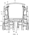
FIG. 1 is a schematic, three-dimensional view of a front cabin frame assembly according to an embodiment of the present invention. -
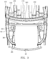
FIG. 2 is a schematic, bottom view of the front cabin frame assembly ofFIG. 1 . -
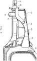
FIG. 3 is a schematic, top view of the front cabin frame assembly ofFIG. 1 . -
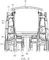
FIG. 4 is a schematic, side view of the front cabin frame assembly ofFIG. 1 . -
FIG. 5 is a schematic, three-dimensional view of some parts of the front cabin frame assembly ofFIG. 1 . -
FIG. 6 is a schematic, bottom view of load transfer paths of the front cabin frame assembly ofFIG. 1 when subject to a head-on collision. -
FIG. 7 is a schematic, side view of load transfer paths of the front cabin frame assembly ofFIG. 1 when subject to a head-on collision. - In order to further illustrate the techniques and effect of the present invention adopted for achieving predetermined invention purpose, exemplary embodiments, structures, features and the effects of the present invention will be described thoroughly in conjunction with the accompanying drawings and the preferred embodiments.
- Referring to
FIG. 1 to FIG. 4 , the front cabin frame assembly of an embodiment of the present invention includes abumper beam 10, twoenergy absorbing boxes 20, two frontbeam front sections 30, twoupper side beams 40, two frontbeam connection brackets 50, twofront headlamp crossbeams 60, two frontmodule mounting pillars 70, acowl reinforcement crossbeam 80, two cowlouter reinforcements 90, afront tower 100, twoA-pillars 110, two front beamrear sections 120, twoouter connection brackets 130, twoinner connection brackets 140, awindshield crossbeam 150, adrip rail 160, amiddle channel 170 and two middlechannel side beams 180. - Referring to
FIG. 1 andFIG. 2 , thebumper beam 10 is disposed in front of theenergy absorbing boxes 20, and theenergy absorbing boxes 20 are disposed in front of the frontbeam front sections 30. Theenergy absorbing boxes 20 are disposed at two opposite ends of thebumper beam 10 and threadedly connected with front ends of the frontbeam front sections 30. The frontbeam front section 30 extends along a length direction (longitudinal direction) of the vehicle body, and thecowl reinforcement crossbeam 80 extends along a width direction (lateral direction) of the vehicle body. Two opposite ends of thecowl reinforcement crossbeam 80 are connected with root portions of the frontbeam front sections 30 respectively. Thebumper beam 10, theenergy absorbing boxes 20, the frontbeam front sections 30 and the front beam reinforcement crossbeam 80 cooperatively connected to form an enclosed frame having a shape of "". This stable structure is capable of improving collision performance, the flexural and torsional stiffness and the NVH performance of the front cabin. - Referring to
FIG. 1 to FIG. 3 , theupper side beams 40 are disposed at outer sides of the frontbeam front sections 30 along the width direction of the vehicle body. Front ends of the upper side beams 40 are connected with the front ends of the frontbeam front sections 30 through the frontbeam connection brackets 50. Root portions of the upper side beams 40 are connected with the A-pillars 110. In an embodiment of the present invention, the front ends of the frontbeam front sections 30 are connected with the front ends of the upper side beams 40 through the frontbeam connection brackets 50, the root portions of the frontbeam front sections 30 are connected with thecowl reinforcement crossbeams 80, and the root portions of the upper side beams 40 are connected with the A-pillars 110, thereby providing two load transfer paths along the length direction of the vehicle body, that is to say, the impact force could be transferred along the frontbeam front section 30 and theupper side beam 40, and the collision energy could be absorbed and distributed effectively. - More concretely, accompanying with
FIG. 4 , theupper side beam 40 includes afirst portion 41, asecond portion 42 and athird portion 43. Thefirst portion 41 is connected with the front end of the frontbeam front section 30, and thethird portion 43 is connected with an upper portion of the A-pillar 110. A height of thefirst portion 41 is lower than a height of thethird portion 43, this is because under the consideration of layout space requirement such as avoid the headlamp, the smaller the height difference between thefirst portion 41 and thethird portion 43 is, the better the collision performance of theupper beam 40 is, due to the load transfer path along theupper side beam 40 is more straight. Thesecond portion 42 connects thefirst portion 41 with thethird portion 43 and is configured in arc shape. The arc-shaped configuration of thesecond portion 42 could avoid tire envelope and extend load absorb and transfer path, so that theupper side beam 40 could absorb and transfer the collision energy more effectively. In addition, the three portions of theupper side beam 40 could be arranged in different materials, for example, thefirst portion 41 and thesecond portion 42 are made of high-strength steel with a lower yield strength, while thethird portion 43 is made of high-strength steel with a higher yield strength, thereby making the yield strength of thefirst portion 41, thesecond portion 42 and thethird portion 43 increases gradually, and further making the entire structure of theupper side beam 40 be soft in front and hard in back, and weak in front and strong in back, so that the front portion of theupper side beam 40 could fully collapse and effectively absorb collision energy, making the rear portion of theupper side beam 40 could dissipate and transfer the rest of the collision energy effectively. - Furthermore, the height of the front end of the
first portion 41 is higher than a height of the front end of the frontbeam front section 30 along a height direction of the vehicle body. Moreover, the frontmost of thefirst portion 41, i.e., the frontmost of theupper side beam 40 extends beyond the rear end of the energy absorbing box 20 (i.e., the frontmost of theupper side beam 40 locates slightly in front of the rear end of the energy absorbing box 20). Due to the frontmost of theupper side beam 40 extends beyond the rear end of theenergy absorbing box 20, the obstacle could contact with theupper side beam 40 as it contacts with the front end of the frontbeam front section 30 in the case that thebumper beam 10 and theenergy absorbing box 20 already collapsed and absorbed the collision energy effectively, so that the collision energy could be dissipated and transferred promptly and effectively. Due to the height of the front end of thefirst portion 41 is higher than the height of the front end of the frontbeam front section 30 along the height direction of the vehicle body, the collision energy could be transferred to the front end of thefront beam 30 and theupper side beam 40, meanwhile, the height difference of two opposite ends of theupper side beam 40 is decreased, and a perfect energy absorb and transfer effect is obtained. Moreover, acovering plate 411 is disposed at the frontmost of thefirst portion 41, which prevents the obstacle from invading in an inner compartment of theupper side beam 40 and reducing the energy absorb and transfer effect of the front end of theupper side beam 40. - In addition, in this embodiment, a plurality of
energy absorbing ribs 421 are disposed at a lower part of a middle portion of thesecond portion 42 to benefit thefirst portion 41 and thesecond portion 42 of theupper side beam 40 to fully collapse and effectively absorb the collision energy, and decrease the impact of the rear portion of the upper side beam 40 (i.e., the third portion 43) on the A-pillar 110. Meanwhile, the transverse area of thethird portion 43 gradually increases from an end connected with thesecond portion 42 towards an end connected with the A-pillar 110, thereby forming a compartment between thethird portion 43 and the A-pillar 110, which facilitates to dissipate the collision energy to the top end and the bottom end of the A-pillar 110 and further transfer the energy to a top portion and a bottom portion of the side wall of the vehicle body. In the embodiment, a width of theupper side beam 40 substantially equals to a width of the A-pillar 110 along the width direction of the vehicle body, which prevents a curved structure being formed between theupper side beam 40 and the A-pillar 110, and further ensures the collision energy be transferred along a straight line. - Moreover, accompany referring to
FIG. 5 , the front end of thefirst portion 41 is laterally connected with the front end of the frontbeam front section 30 through the frontbeam connection bracket 50, the front end of thesecond portion 42 is connected with the front end of the frontbeam front section 30 through thefront headlamp crossbeam 60 and the frontmodule mounting pillar 70, and a middle rear end of thesecond portion 42 is connected with a middle portion of the frontbeam front section 30 through thefront tower 100, thereby forming a frame having a shape of "", which obviously improves the performance of 25% offset collision, and further increases the flexural and torsional stiffness of the vehicle body and improves the NVH performance. - Referring back to
FIG. 1 andFIG. 2 , thewindshield crossbeam 150 is disposed above the frame of the dash panel with left and right ends thereof connected with the A-pillar 10, and thecowl reinforcement crossbeam 80 is disposed below the frame of the dash panel and connected with the A-pillar 110, thereby forming two continuously connected reinforcement structures along lateral direction. The cowlouter reinforcements 90, thecowl reinforcement crossbeam 80, the frontbeam front section 30 and the A-pillars 110 cooperatively form a continuously connected structure along the width direction of the vehicle body, i.e., thewindshield crossbeam 150, the A-pillars 110, thecowl reinforcement crossbeam 80 and the cowlouter reinforcements 90 cooperatively form a frame having a shape of "", which further improves the capabilities of resisting flex and torsion under external load, thereby increasing the flexural and torsional stiffness as well as improving the flex and torsion mode of the vehicle body, and further improving the NVH performance. - The front beam
rear section 120 is connected with the root portion of the frontbeam front section 30 and extends along the length direction of the vehicle body. Theouter connection bracket 130 connects the front beamrear section 120 with the A-pillar 110. Theinner connection bracket 140 connects the front beamrear section 120 with the middlechannel side beam 180. In the embodiment, theouter connection bracket 130 and theinner connection bracket 140 are disposed at two opposite sides of a position of the front beamrear section 120, which is disposed adjacent to the root portion of the frontbeam front section 30 along a length direction of the front beamrear section 120, so that the front beamrear section 120, theouter connection bracket 130, and theinner connection bracket 140 cooperatively form a continuous overlapping structure along the width direction of the vehicle body, which improves the capabilities of resisting flex and torsion under external load as well, and is capable of dissipating the collision energy on the subframe from the front beamrear section 120 to the doorsill (not shown in Figures) and the middlechannel side beam 180 when the vehicle is subject to a head-on collision, thereby increasing strength of subframe installation points on the frame. In addition, the middle portion of thecowl reinforcement crossbeam 80 connects with themiddle channel 170 and the middlechannel side beam 180 to form a continuously connected structure, which could effectively dissipate the collision energy and improve local mode of the front portion of themiddle channel 170 and further increases the flexural and torsional stiffness of the entire vehicle. - The operating theory of the front cabin frame assembly in head-on collision is described as follow.
- Referring to
FIG. 6 andFIG. 7 , when the vehicle body is subject to a head-on collision, the obstacle impacts thebummer beam 10 firstly, thebumper beam 10 transfers the impact force to theenergy absorbing box 20 and the front end of the frontbeam front section 30, furthermore, when thebumper beam 10 and theenergy absorbing box 20 fully collapse and effectively absorb the collision energy, the obstacle contacts with the front end of the frontbeam front section 30 as well as the front end of theupper beam section 40, and the impact force on the frontbeam front section 30 and theupper side beam 40 could be dissipated through the frontbeam connection bracket 50, thefront headlamp crossbeam 60 and the frontmodule mounting pillar 70, so that the impact force could be dissipated in the longitudinal direction of the vehicle body to beams at the rear portion of the front cabin frame assembly by two load transfer paths (indicated by the arrows shown inFIG. 6 ) and along the frontbeam front section 30 and theupper side beam 40. The load transfer manner makes the impact force could be transferred by the entire frame structure of the front cabin, thereby preventing a single beam from becoming instability due to suffer excessive impact load. Meanwhile, in the present invention, the longitudinal beams are connected laterally through thecowl reinforcement crossbeam 80, thecowl reinforcement 90, theouter connection bracket 130 and theinner connection bracket 140, so that the impact force could be dissipated laterally (indicated by the arrows shown inFIG. 6 ) towards thecowl reinforcement crossbeam 80, the dash panel (not shown in Figures), themiddle channel 170 and the middlechannel side beam 180 as the impact force is dissipated backwards along the frontbeam front section 30 and theupper side beam 40, therefore, the collision energy could be dissipated to each region effectively, accordingly decreases the invasion rate in the passenger compartment effectively and ensures the safety of the passenger. On the other hand, the structure that the transverse area of thethird portion 43 of theupper side beam 40 varies could dissipate the collision energy effectively towards the top end and the bottom end of the A-pillar 110 (indicated by the arrows shown inFIG. 7 ) and further towards the top and the bottom portions of the side wall so that the impact force is further dissipated and the collision energy is distributed along two load transfer paths reasonably, which makes the load transfer path be more sufficient and improves the collision safety of the entire vehicle. - As mentioned above, the front cabin frame assembly of the present invention includes the following advantages.
- (1) The front cabin frame assembly of the present invention includes two load transfer paths for transferring collision energy, makes the front cabin frame could absorb the head-on collision energy effectively and results the load transfer path be more reasonable, thereby decreasing the injury of the passengers during collision, and increasing the collision safety of the entire vehicle.
- (2) The frontmost of the first portion of the upper side beam disposes a covering plate, the second portion disposes a plurality of energy absorbing ribs and is configured to arc shape which slightly bends upward, the third portion is configured to a structure with the transverse area thereof gradually increases, and the upper side beam is configured to soft in front and hard in back, and weak in front and strong in back, therefore could absorb and dissipate the collision energy effectively, and accordingly improve the collision performance of the front portion of the vehicle body, especially improve the performance of 25% offset collision.
- (3) The front cabin frame assembly of the present invention includes a plurality of enclosed structures having a shape of "" and a plurality of continuously connected overlapping structures along lateral and longitudinal directions, which could improve the flexural and torsional stiffness and the mode of the vehicle body and further improves the NVH performance.
- The descriptions above are embodiments of the present invention only and are not used, by any way, to limit the present invention. Although the present invention has been described with reference to the above embodiments, those embodiments are not used to limit the present invention, it will be apparent to anyone of ordinary skill in the art that slight changes or modifications to the described embodiments may be made to become equivalent embodiments without departing from the technique scope of the present invention. On the contrary, any slight and simple changes, equivalent variations and modifications according to the spirit of the present invention should fall within the technique scope of the present invention.
- In the present invention, the front end of the upper side beam is connected with the front end of the front beam front section through the front beam connection bracket, the root portion of the front beam front section is connected with the cowl reinforcement crossbeam, the root portion of the upper side beam is connected with the A-pillar, thereby forming two longitudinal load transfer paths. The two longitudinal load transfer paths are designed to include a plurality of continuously connected overlapping crossbeams, thereby forming an enclosed ring-like front cabin frame. Therefore, the collision energy could be transferred along two paths and by the upper side beam and the front beam when the vehicle body is subject to a head-on collision. Furthermore, the collision energy is absorbed and transferred by a plurality of longitudinal beams and a plurality of lateral beams, which results the head-on collision energy be absorbed effectively and the load transfer path be more reasonable, thereby decreasing the deformation of the passenger compartment and the injury of the passengers, and increasing the collision safety of the entire vehicle. Meanwhile, the enclosed ring-like front cabin frame includes a plurality of continuously connected overlapping beams along lateral and longitudinal directions, which improves the flexural and torsional stiffness of the vehicle body and further improves the NVH performance.
Claims (11)
- A front cabin frame assembly, characterized by comprising: a front beam front section (30), an upper side beam (40), a cowl reinforcement crossbeam (80), a cowl outer reinforcement (90) and an A-pillar (110), a front end of the front beam front section (30) laterally connected with a front end of the upper side beam (40), a root portion of the front beam front section (30) connected with the cowl reinforcement crossbeam (80), a root portion of the upper side beam (40) connected with the A-pillar (110), the cowl outer reinforcement (90) connected with the root portion of the front beam front section (30) and the A-pillar (110).
- The front cabin frame assembly according to claim 1, wherein the front cabin frame assembly further comprises an energy absorbing box (20) disposed in the front of the front beam front section (30) and a bumper beam (10) disposed in the front of the energy absorbing box (20), the bumper beam (10), the energy absorbing box (20), the front beam front section (30) and the cowl reinforcement crossbeam (80) cooperatively form a frame having a shape of "".

- The front cabin frame assembly according to claim 2, wherein the upper side beam (40) is located at outer side of the front beam front section (30) along a width direction of a vehicle body, the frontmost end of the upper side beam (40) extends beyond a rear end of the energy absorbing box (20).
- The front cabin frame assembly according to claim 1, wherein the upper side beam (40) comprises a first portion (41), a second portion (42) and a third portion (43), the first portion (41) is connected with the front beam front section (30), the third portion (43) is connected with the A-pillar (110), the second portion (42) connects the first portion (41) with the third portion (43) and is configured in arc shape, a height of the first portion (41) is lower than a height of the third portion (43).
- The front cabin frame assembly according to claim 4, wherein a front end of the second portion (42) is connected with a front end of the front beam front section (30) through a front headlamp crossbeam (60) and a front module mounting pillar (70), a front end of the first portion (41) is connected with the front end of front beam front section (30) through a front beam connection bracket (50), a height of the front end of the first portion (41) is higher than a height of the front beam front section (30) along a height direction of a vehicle body.
- The front cabin frame assembly according to claim 5, wherein the front cabin frame assembly further comprises a drip rail (160) and a front tower (100) disposed between the front beam front section (30) and the upper side beam (40), an upper portion of the front tower (100) is connected with two opposite ends of the drip rail (160), the front beam connection bracket (50), the front tower (100), the front beam front section (30) and the upper side beam (40) cooperatively form a frame having a shape of "".

- The front cabin frame assembly according to claim 4, wherein the frontmost of the first portion (41) disposes a covering plate (411), and a lower part of a middle portion of the second portion (42) disposes a plurality of energy absorbing ribs (421).
- The front cabin frame assembly according to claim 4, wherein a transverse area of the third portion (43) gradually increases from an end connected with the second portion (42) towards an end connected with the A-pillar (110), the third portion (43) and the A-pillar (110) connect to a continuously connected structure.
- The front cabin frame assembly according to claim 4, wherein the yield strength of the first portion (41), the second portion (42) and the third portion (43) increases gradually.
- The front cabin frame assembly according to claim 1, wherein the front cabin frame assembly further comprises a front beam rear section (120), an outer connection bracket (130), an inner connection bracket (140) and a middle channel side beam (180), the front beam rear section (120) is connected with the root portion of the front beam front section (30), the outer connection bracket (130) is connected with the front beam rear section (120) and the A-pillar (110), the inner connection bracket (140) is connected with the front beam rear section (120) and the middle channel side beam (180).
- The front cabin frame assembly according to claim 10, wherein the front cabin frame assembly further comprises a middle channel (170) and a windshield crossbeam (150) disposed above the cowl reinforcement crossbeam (80), the windshield crossbeam (150), the A-pillar (110), the cowl reinforcement crossbeam (80) and the cowl outer reinforcement (90) cooperatively form a frame having a shape of "", a middle portion of the cowl reinforcement crossbeam (80) is connected with the middle channel (170) and the middle channel side beam (180) to form a continuously connected structure.
Applications Claiming Priority (2)
| Application Number | Priority Date | Filing Date | Title |
|---|---|---|---|
| CN201510946358.8A CN106882272A (en) | 2015-12-16 | 2015-12-16 | Forward engine room frame assembly |
| PCT/CN2016/097569 WO2017101513A1 (en) | 2015-12-16 | 2016-08-31 | Front cabin frame assembly |
Publications (4)
| Publication Number | Publication Date |
|---|---|
| EP3392123A1 true EP3392123A1 (en) | 2018-10-24 |
| EP3392123A4 EP3392123A4 (en) | 2019-08-28 |
| EP3392123B1 EP3392123B1 (en) | 2024-07-03 |
| EP3392123C0 EP3392123C0 (en) | 2024-07-03 |
Family
ID=59055655
Family Applications (1)
| Application Number | Title | Priority Date | Filing Date |
|---|---|---|---|
| EP16874573.5A Active EP3392123B1 (en) | 2015-12-16 | 2016-08-31 | Front cabin frame assembly |
Country Status (4)
| Country | Link |
|---|---|
| US (1) | US10543873B2 (en) |
| EP (1) | EP3392123B1 (en) |
| CN (1) | CN106882272A (en) |
| WO (1) | WO2017101513A1 (en) |
Cited By (1)
| Publication number | Priority date | Publication date | Assignee | Title |
|---|---|---|---|---|
| EP4477499A4 (en) * | 2022-07-20 | 2026-02-18 | Voyah Automobile Tech Company Ltd | FRONT CAB AND VEHICLE |
Families Citing this family (41)
| Publication number | Priority date | Publication date | Assignee | Title |
|---|---|---|---|---|
| US10661832B2 (en) * | 2016-09-07 | 2020-05-26 | Thunder Power Electric Vehicle Development Company Limited | Angle and geometry of the front cross member |
| KR102371239B1 (en) * | 2017-04-21 | 2022-03-04 | 현대자동차 주식회사 | Front vehicle body reinforcing structure |
| KR20180129084A (en) * | 2017-05-25 | 2018-12-05 | 현대자동차주식회사 | Side member with impact absorbing structure |
| CN109204520B (en) * | 2017-06-30 | 2021-06-18 | 比亚迪股份有限公司 | Body Structure and Vehicle |
| CN109204544B (en) | 2017-06-30 | 2020-11-06 | 比亚迪股份有限公司 | Body Structure and Vehicle |
| CN109204527B (en) * | 2017-06-30 | 2021-04-20 | 比亚迪股份有限公司 | Body Structure and Vehicle |
| CN109204497B (en) * | 2017-06-30 | 2021-01-01 | 比亚迪股份有限公司 | Vehicle body structure and vehicle |
| CN108016506B (en) * | 2017-11-09 | 2020-02-21 | 广州汽车集团股份有限公司 | vehicle cabin assembly |
| CN107963130B (en) * | 2017-11-22 | 2019-08-13 | 威马智慧出行科技(上海)有限公司 | Front wall assembly and automobile including it |
| CN108001533A (en) * | 2017-11-22 | 2018-05-08 | 奇瑞汽车股份有限公司 | Front deck vehicle frame |
| JP7035848B2 (en) * | 2018-06-27 | 2022-03-15 | トヨタ自動車株式会社 | Vehicle lower body structure |
| CN109823410B (en) * | 2019-02-28 | 2024-04-19 | 东风小康汽车有限公司重庆分公司 | Front engine room sealing plate connecting structure |
| CN109910802B (en) * | 2019-03-06 | 2021-05-25 | 宁波吉利汽车研究开发有限公司 | Novel small offset structure |
| WO2020217085A1 (en) * | 2019-04-23 | 2020-10-29 | Arcelormittal | Tunnel having integrated lateral reinforcements |
| CN111619670B (en) * | 2019-09-19 | 2021-07-13 | 长城汽车股份有限公司 | Front body structure and car |
| CN112572614B (en) * | 2019-09-30 | 2022-06-21 | 广州汽车集团股份有限公司 | Beam structure assembly for vehicle and vehicle with beam structure assembly |
| CN112572618A (en) * | 2019-09-30 | 2021-03-30 | 比亚迪股份有限公司 | Vehicle front cabin structure and vehicle |
| CN113002633A (en) * | 2019-12-19 | 2021-06-22 | 观致汽车有限公司 | Front cabin skeleton assembly |
| CN113044117A (en) * | 2019-12-26 | 2021-06-29 | 观致汽车有限公司 | Upper longitudinal beam assembly of vehicle front cabin and vehicle with same |
| CN111152847B (en) * | 2020-01-08 | 2021-06-01 | 上海龙创汽车设计股份有限公司 | Automobile framework reinforcing structure |
| WO2022041185A1 (en) * | 2020-08-31 | 2022-03-03 | 华为技术有限公司 | Front structure of vehicle and vehicle |
| CN112622795B (en) * | 2020-12-28 | 2021-08-24 | 湖南大学 | Head-on collision resistant vehicle structure and manufacturing method |
| WO2022155905A1 (en) * | 2021-01-22 | 2022-07-28 | 浙江吉利控股集团有限公司 | Pillar structure, vehicle body structure, and vehicle |
| CN114954663A (en) * | 2021-02-19 | 2022-08-30 | 威马智慧出行科技(上海)股份有限公司 | Protective structure and vehicle to vehicle little overlapping collision |
| JP7604985B2 (en) * | 2021-03-29 | 2024-12-24 | マツダ株式会社 | Body structure |
| CN113147908A (en) * | 2021-04-20 | 2021-07-23 | 重庆长安汽车股份有限公司 | Front end structure of vehicle body |
| CN114932953B (en) * | 2021-06-29 | 2023-05-05 | 比亚迪股份有限公司 | Vehicle body frame and vehicle with same |
| CN113460166B (en) * | 2021-06-30 | 2022-04-01 | 东风汽车集团股份有限公司 | A modular offset bump reinforcement structure |
| CN113443010B (en) * | 2021-07-06 | 2022-09-09 | 合肥长安汽车有限公司 | Rear cross beam assembly of automobile cabin |
| CN113771954B (en) * | 2021-08-31 | 2023-09-22 | 重庆长安汽车股份有限公司 | Pure electric vehicles cabin prevents invading structure |
| JP7553414B2 (en) * | 2021-09-09 | 2024-09-18 | トヨタ自動車株式会社 | vehicle |
| CN113968285B (en) * | 2021-10-26 | 2023-01-10 | 东风越野车有限公司 | Front engine room structure of off-road vehicle body |
| CN116252864A (en) * | 2021-12-09 | 2023-06-13 | 广州汽车集团股份有限公司 | Automobile cabin frame structure and automobile |
| JP7485708B2 (en) | 2022-03-10 | 2024-05-16 | 本田技研工業株式会社 | Vehicle underbody structure |
| CN115158479B (en) * | 2022-06-29 | 2023-09-22 | 重庆长安汽车股份有限公司 | Automobile body front cabin integral type structure and car based on platform framework |
| CN116252863B (en) * | 2023-01-19 | 2025-05-27 | 东风汽车集团股份有限公司 | Front cabin frame and vehicle |
| CN118850189B (en) * | 2023-04-28 | 2025-11-18 | 长城汽车股份有限公司 | Front frame of the vehicle body and vehicle |
| CN116691843B (en) * | 2023-05-29 | 2025-09-09 | 重庆长安汽车股份有限公司 | Front-end frame structure and car |
| CN116654107B (en) * | 2023-06-26 | 2026-02-27 | 浙江吉利控股集团有限公司 | For use in vehicle body front longitudinal beam assembly, front frame assembly and vehicle |
| CN119611521B (en) * | 2023-09-13 | 2025-11-04 | 比亚迪股份有限公司 | Body frame structure and vehicle |
| CN117601970B (en) * | 2023-12-20 | 2026-01-27 | 蔚来汽车科技(安徽)有限公司 | Front longitudinal beam rear section part of vehicle and vehicle |
Family Cites Families (21)
| Publication number | Priority date | Publication date | Assignee | Title |
|---|---|---|---|---|
| JPH07228267A (en) | 1994-02-17 | 1995-08-29 | Mitsubishi Motors Corp | Strength member structure of car body |
| JP2004106704A (en) * | 2002-09-18 | 2004-04-08 | Fuji Heavy Ind Ltd | Car body front structure |
| JP4144385B2 (en) * | 2003-03-12 | 2008-09-03 | 三菱自動車工業株式会社 | Connecting structure at the front of the car compartment |
| JP4304537B2 (en) | 2007-02-23 | 2009-07-29 | トヨタ自動車株式会社 | Vehicle skeleton structure |
| JP5029328B2 (en) * | 2007-12-05 | 2012-09-19 | マツダ株式会社 | Front body structure of automobile |
| DE102009056840A1 (en) * | 2009-12-03 | 2011-06-09 | GM Global Technology Operations LLC, ( n. d. Ges. d. Staates Delaware ), Detroit | Substructure structure of a motor vehicle body |
| CN102358349B (en) | 2011-08-11 | 2013-06-12 | 奇瑞汽车股份有限公司 | Front body framework structure of automobile |
| US20150061320A1 (en) * | 2012-01-10 | 2015-03-05 | Honday Motor Co., Ltd. | Vehicle body frame structure of motor vehicle |
| US8770653B2 (en) * | 2012-04-16 | 2014-07-08 | Ford Global Technologies, Llc | Bodywork arrangement for a front end and a passenger compartment of a vehicle |
| KR101448747B1 (en) * | 2012-10-02 | 2014-10-08 | 현대자동차 주식회사 | Front vehicle body structure |
| CN202987288U (en) | 2012-12-07 | 2013-06-12 | 北京汽车股份有限公司 | Front fingerboard assembly, engine cabin and automobile |
| DE102014204516B4 (en) * | 2013-03-26 | 2023-06-22 | Subaru Corporation | vehicle body structure |
| CN103770841B (en) * | 2013-05-27 | 2015-05-27 | 广州汽车集团股份有限公司 | A car body skeleton structure |
| CN203306103U (en) * | 2013-05-30 | 2013-11-27 | 长城汽车股份有限公司 | Multi-channel force transferring mechanism, and forward engine room and vehicle comprising same |
| CN203358689U (en) * | 2013-05-31 | 2013-12-25 | 奇瑞汽车股份有限公司 | Vehicle body collision energy absorbing structure |
| CN203637949U (en) | 2013-12-02 | 2014-06-11 | 奇瑞汽车股份有限公司 | Automobile head board assembly |
| CN204415518U (en) | 2015-01-05 | 2015-06-24 | 广州汽车集团股份有限公司 | Front deck longeron rear section structure and automobile |
| CN204623579U (en) * | 2015-04-27 | 2015-09-09 | 北京汽车股份有限公司 | Automobile front wall structure and automobile |
| CN204775483U (en) * | 2015-05-29 | 2015-11-18 | 广州汽车集团股份有限公司 | Car cabin assembly |
| CN204821716U (en) * | 2015-05-29 | 2015-12-02 | 广州汽车集团股份有限公司 | Car cabin assembly |
| CN205273623U (en) * | 2015-12-16 | 2016-06-01 | 广州汽车集团股份有限公司 | Preceding cabin frame assembly |
-
2015
- 2015-12-16 CN CN201510946358.8A patent/CN106882272A/en active Pending
-
2016
- 2016-08-31 US US15/744,731 patent/US10543873B2/en active Active
- 2016-08-31 EP EP16874573.5A patent/EP3392123B1/en active Active
- 2016-08-31 WO PCT/CN2016/097569 patent/WO2017101513A1/en not_active Ceased
Cited By (1)
| Publication number | Priority date | Publication date | Assignee | Title |
|---|---|---|---|---|
| EP4477499A4 (en) * | 2022-07-20 | 2026-02-18 | Voyah Automobile Tech Company Ltd | FRONT CAB AND VEHICLE |
Also Published As
| Publication number | Publication date |
|---|---|
| WO2017101513A1 (en) | 2017-06-22 |
| EP3392123A4 (en) | 2019-08-28 |
| CN106882272A (en) | 2017-06-23 |
| US10543873B2 (en) | 2020-01-28 |
| EP3392123B1 (en) | 2024-07-03 |
| US20180201326A1 (en) | 2018-07-19 |
| EP3392123C0 (en) | 2024-07-03 |
Similar Documents
| Publication | Publication Date | Title |
|---|---|---|
| EP3392123B1 (en) | Front cabin frame assembly | |
| KR102730519B1 (en) | Body for vehicle | |
| US7810878B2 (en) | Vehicle body structure | |
| US10435076B2 (en) | Vehicle engine compartment assembly | |
| JP6372494B2 (en) | Front body structure of the vehicle | |
| KR102383247B1 (en) | Front vehicle body reinforcing structure | |
| JP6432535B2 (en) | Front body structure of the vehicle | |
| CN205273623U (en) | Preceding cabin frame assembly | |
| KR102440606B1 (en) | Front vehicle body reinforcing structure | |
| KR101371838B1 (en) | Structure for dispersing collision energy of front pillar during car crash | |
| CN107074296B (en) | Support device for the front compartment of a passenger car and a passenger car | |
| CN105313976B (en) | For vehicle vehicle body and there is its vehicle | |
| CN108297940A (en) | Car body frame structure | |
| KR102567273B1 (en) | Vehicle body structure | |
| US9266567B1 (en) | Vehicles having a dash panel reinforcement gusset | |
| CN116096623A (en) | Body structure for a motor vehicle | |
| US8888167B2 (en) | Body structure of vehicle | |
| US9290209B2 (en) | Vehicle body lower structure | |
| JP6248959B2 (en) | Vehicle skeleton structure | |
| JP5630615B2 (en) | Vehicle body structure | |
| CN214689769U (en) | A front end structure and vehicle | |
| KR20120051539A (en) | Reinforced structure of front suspension for vehicle | |
| CN110962936B (en) | Cross member structure and vehicle frame | |
| EP4108554A1 (en) | A cab-over engine truck | |
| CN114056433B (en) | Lower body structure of vehicle |
Legal Events
| Date | Code | Title | Description |
|---|---|---|---|
| STAA | Information on the status of an ep patent application or granted ep patent |
Free format text: STATUS: THE INTERNATIONAL PUBLICATION HAS BEEN MADE |
|
| PUAI | Public reference made under article 153(3) epc to a published international application that has entered the european phase |
Free format text: ORIGINAL CODE: 0009012 |
|
| STAA | Information on the status of an ep patent application or granted ep patent |
Free format text: STATUS: REQUEST FOR EXAMINATION WAS MADE |
|
| 17P | Request for examination filed |
Effective date: 20180116 |
|
| AK | Designated contracting states |
Kind code of ref document: A1 Designated state(s): AL AT BE BG CH CY CZ DE DK EE ES FI FR GB GR HR HU IE IS IT LI LT LU LV MC MK MT NL NO PL PT RO RS SE SI SK SM TR |
|
| AX | Request for extension of the european patent |
Extension state: BA ME |
|
| RIN1 | Information on inventor provided before grant (corrected) |
Inventor name: YE, BAOWEN Inventor name: GENG, FURONG Inventor name: WU, CHUNFU Inventor name: YANG, JINXIU Inventor name: CHEN, DONG Inventor name: YUAN, HUANQUAN |
|
| DAV | Request for validation of the european patent (deleted) | ||
| DAX | Request for extension of the european patent (deleted) | ||
| A4 | Supplementary search report drawn up and despatched |
Effective date: 20190731 |
|
| RIC1 | Information provided on ipc code assigned before grant |
Ipc: B62D 25/08 20060101AFI20190725BHEP Ipc: B60R 19/34 20060101ALI20190725BHEP Ipc: B62D 21/15 20060101ALI20190725BHEP Ipc: B62D 25/20 20060101ALI20190725BHEP |
|
| STAA | Information on the status of an ep patent application or granted ep patent |
Free format text: STATUS: EXAMINATION IS IN PROGRESS |
|
| 17Q | First examination report despatched |
Effective date: 20201216 |
|
| GRAP | Despatch of communication of intention to grant a patent |
Free format text: ORIGINAL CODE: EPIDOSNIGR1 |
|
| STAA | Information on the status of an ep patent application or granted ep patent |
Free format text: STATUS: GRANT OF PATENT IS INTENDED |
|
| INTG | Intention to grant announced |
Effective date: 20240416 |
|
| GRAS | Grant fee paid |
Free format text: ORIGINAL CODE: EPIDOSNIGR3 |
|
| GRAA | (expected) grant |
Free format text: ORIGINAL CODE: 0009210 |
|
| STAA | Information on the status of an ep patent application or granted ep patent |
Free format text: STATUS: THE PATENT HAS BEEN GRANTED |
|
| AK | Designated contracting states |
Kind code of ref document: B1 Designated state(s): AL AT BE BG CH CY CZ DE DK EE ES FI FR GB GR HR HU IE IS IT LI LT LU LV MC MK MT NL NO PL PT RO RS SE SI SK SM TR |
|
| REG | Reference to a national code |
Ref country code: CH Ref legal event code: EP |
|
| REG | Reference to a national code |
Ref country code: DE Ref legal event code: R096 Ref document number: 602016088266 Country of ref document: DE |
|
| U01 | Request for unitary effect filed |
Effective date: 20240703 |
|
| U07 | Unitary effect registered |
Designated state(s): AT BE BG DE DK EE FI FR IT LT LU LV MT NL PT SE SI Effective date: 20240711 |
|
| U20 | Renewal fee for the european patent with unitary effect paid |
Year of fee payment: 9 Effective date: 20240925 |
|
| PG25 | Lapsed in a contracting state [announced via postgrant information from national office to epo] |
Ref country code: NO Free format text: LAPSE BECAUSE OF FAILURE TO SUBMIT A TRANSLATION OF THE DESCRIPTION OR TO PAY THE FEE WITHIN THE PRESCRIBED TIME-LIMIT Effective date: 20241003 |
|
| PG25 | Lapsed in a contracting state [announced via postgrant information from national office to epo] |
Ref country code: GR Free format text: LAPSE BECAUSE OF FAILURE TO SUBMIT A TRANSLATION OF THE DESCRIPTION OR TO PAY THE FEE WITHIN THE PRESCRIBED TIME-LIMIT Effective date: 20241004 Ref country code: PL Free format text: LAPSE BECAUSE OF FAILURE TO SUBMIT A TRANSLATION OF THE DESCRIPTION OR TO PAY THE FEE WITHIN THE PRESCRIBED TIME-LIMIT Effective date: 20240703 |
|
| PG25 | Lapsed in a contracting state [announced via postgrant information from national office to epo] |
Ref country code: IS Free format text: LAPSE BECAUSE OF FAILURE TO SUBMIT A TRANSLATION OF THE DESCRIPTION OR TO PAY THE FEE WITHIN THE PRESCRIBED TIME-LIMIT Effective date: 20241103 |
|
| PG25 | Lapsed in a contracting state [announced via postgrant information from national office to epo] |
Ref country code: CZ Free format text: LAPSE BECAUSE OF FAILURE TO SUBMIT A TRANSLATION OF THE DESCRIPTION OR TO PAY THE FEE WITHIN THE PRESCRIBED TIME-LIMIT Effective date: 20240703 Ref country code: HR Free format text: LAPSE BECAUSE OF FAILURE TO SUBMIT A TRANSLATION OF THE DESCRIPTION OR TO PAY THE FEE WITHIN THE PRESCRIBED TIME-LIMIT Effective date: 20240703 |
|
| PG25 | Lapsed in a contracting state [announced via postgrant information from national office to epo] |
Ref country code: RS Free format text: LAPSE BECAUSE OF FAILURE TO SUBMIT A TRANSLATION OF THE DESCRIPTION OR TO PAY THE FEE WITHIN THE PRESCRIBED TIME-LIMIT Effective date: 20241003 Ref country code: ES Free format text: LAPSE BECAUSE OF FAILURE TO SUBMIT A TRANSLATION OF THE DESCRIPTION OR TO PAY THE FEE WITHIN THE PRESCRIBED TIME-LIMIT Effective date: 20240703 |
|
| PG25 | Lapsed in a contracting state [announced via postgrant information from national office to epo] |
Ref country code: RS Free format text: LAPSE BECAUSE OF FAILURE TO SUBMIT A TRANSLATION OF THE DESCRIPTION OR TO PAY THE FEE WITHIN THE PRESCRIBED TIME-LIMIT Effective date: 20241003 Ref country code: PL Free format text: LAPSE BECAUSE OF FAILURE TO SUBMIT A TRANSLATION OF THE DESCRIPTION OR TO PAY THE FEE WITHIN THE PRESCRIBED TIME-LIMIT Effective date: 20240703 Ref country code: NO Free format text: LAPSE BECAUSE OF FAILURE TO SUBMIT A TRANSLATION OF THE DESCRIPTION OR TO PAY THE FEE WITHIN THE PRESCRIBED TIME-LIMIT Effective date: 20241003 Ref country code: IS Free format text: LAPSE BECAUSE OF FAILURE TO SUBMIT A TRANSLATION OF THE DESCRIPTION OR TO PAY THE FEE WITHIN THE PRESCRIBED TIME-LIMIT Effective date: 20241103 Ref country code: HR Free format text: LAPSE BECAUSE OF FAILURE TO SUBMIT A TRANSLATION OF THE DESCRIPTION OR TO PAY THE FEE WITHIN THE PRESCRIBED TIME-LIMIT Effective date: 20240703 Ref country code: GR Free format text: LAPSE BECAUSE OF FAILURE TO SUBMIT A TRANSLATION OF THE DESCRIPTION OR TO PAY THE FEE WITHIN THE PRESCRIBED TIME-LIMIT Effective date: 20241004 Ref country code: ES Free format text: LAPSE BECAUSE OF FAILURE TO SUBMIT A TRANSLATION OF THE DESCRIPTION OR TO PAY THE FEE WITHIN THE PRESCRIBED TIME-LIMIT Effective date: 20240703 Ref country code: CZ Free format text: LAPSE BECAUSE OF FAILURE TO SUBMIT A TRANSLATION OF THE DESCRIPTION OR TO PAY THE FEE WITHIN THE PRESCRIBED TIME-LIMIT Effective date: 20240703 |
|
| REG | Reference to a national code |
Ref country code: CH Ref legal event code: PL |
|
| PG25 | Lapsed in a contracting state [announced via postgrant information from national office to epo] |
Ref country code: SM Free format text: LAPSE BECAUSE OF FAILURE TO SUBMIT A TRANSLATION OF THE DESCRIPTION OR TO PAY THE FEE WITHIN THE PRESCRIBED TIME-LIMIT Effective date: 20240703 |
|
| PG25 | Lapsed in a contracting state [announced via postgrant information from national office to epo] |
Ref country code: MC Free format text: LAPSE BECAUSE OF FAILURE TO SUBMIT A TRANSLATION OF THE DESCRIPTION OR TO PAY THE FEE WITHIN THE PRESCRIBED TIME-LIMIT Effective date: 20240703 Ref country code: CH Free format text: LAPSE BECAUSE OF NON-PAYMENT OF DUE FEES Effective date: 20240831 |
|
| PG25 | Lapsed in a contracting state [announced via postgrant information from national office to epo] |
Ref country code: SK Free format text: LAPSE BECAUSE OF FAILURE TO SUBMIT A TRANSLATION OF THE DESCRIPTION OR TO PAY THE FEE WITHIN THE PRESCRIBED TIME-LIMIT Effective date: 20240703 |
|
| PLBE | No opposition filed within time limit |
Free format text: ORIGINAL CODE: 0009261 |
|
| STAA | Information on the status of an ep patent application or granted ep patent |
Free format text: STATUS: NO OPPOSITION FILED WITHIN TIME LIMIT |
|
| 26N | No opposition filed |
Effective date: 20250404 |
|
| GBPC | Gb: european patent ceased through non-payment of renewal fee |
Effective date: 20241003 |
|
| PG25 | Lapsed in a contracting state [announced via postgrant information from national office to epo] |
Ref country code: GB Free format text: LAPSE BECAUSE OF NON-PAYMENT OF DUE FEES Effective date: 20241003 |
|
| PG25 | Lapsed in a contracting state [announced via postgrant information from national office to epo] |
Ref country code: IE Free format text: LAPSE BECAUSE OF NON-PAYMENT OF DUE FEES Effective date: 20240831 |
|
| U1N | Appointed representative for the unitary patent procedure changed after the registration of the unitary effect |
Representative=s name: METIDA; LT |
|
| U20 | Renewal fee for the european patent with unitary effect paid |
Year of fee payment: 10 Effective date: 20250826 |
|
| PG25 | Lapsed in a contracting state [announced via postgrant information from national office to epo] |
Ref country code: RO Free format text: LAPSE BECAUSE OF FAILURE TO SUBMIT A TRANSLATION OF THE DESCRIPTION OR TO PAY THE FEE WITHIN THE PRESCRIBED TIME-LIMIT Effective date: 20240703 |
|
| PG25 | Lapsed in a contracting state [announced via postgrant information from national office to epo] |
Ref country code: CY Free format text: LAPSE BECAUSE OF FAILURE TO SUBMIT A TRANSLATION OF THE DESCRIPTION OR TO PAY THE FEE WITHIN THE PRESCRIBED TIME-LIMIT; INVALID AB INITIO Effective date: 20160831 |
|
| PG25 | Lapsed in a contracting state [announced via postgrant information from national office to epo] |
Ref country code: HU Free format text: LAPSE BECAUSE OF FAILURE TO SUBMIT A TRANSLATION OF THE DESCRIPTION OR TO PAY THE FEE WITHIN THE PRESCRIBED TIME-LIMIT; INVALID AB INITIO Effective date: 20160831 |