EP3392118A1 - Body bolster and railroad vehicle structure provided with same - Google Patents
Body bolster and railroad vehicle structure provided with same Download PDFInfo
- Publication number
- EP3392118A1 EP3392118A1 EP15910742.4A EP15910742A EP3392118A1 EP 3392118 A1 EP3392118 A1 EP 3392118A1 EP 15910742 A EP15910742 A EP 15910742A EP 3392118 A1 EP3392118 A1 EP 3392118A1
- Authority
- EP
- European Patent Office
- Prior art keywords
- bolster
- composite material
- core
- center pin
- mounting seat
- Prior art date
- Legal status (The legal status is an assumption and is not a legal conclusion. Google has not performed a legal analysis and makes no representation as to the accuracy of the status listed.)
- Granted
Links
Images



Classifications
-
- B—PERFORMING OPERATIONS; TRANSPORTING
- B61—RAILWAYS
- B61F—RAIL VEHICLE SUSPENSIONS, e.g. UNDERFRAMES, BOGIES OR ARRANGEMENTS OF WHEEL AXLES; RAIL VEHICLES FOR USE ON TRACKS OF DIFFERENT WIDTH; PREVENTING DERAILING OF RAIL VEHICLES; WHEEL GUARDS, OBSTRUCTION REMOVERS OR THE LIKE FOR RAIL VEHICLES
- B61F1/00—Underframes
- B61F1/08—Details
- B61F1/12—Cross bearers
Definitions
- the present invention relates to a plate-shaped bolster that constitutes an underframe forming a floor surface of a railway car structure body and is provided on a lower surface of the underframe in a railroad tie direction and a railway car structure body including the same.
- a railway car structure body (hereinafter, referred to as "structure body") is a hexahedron structure including an underframe forming a floor surface, side structures erected on both end portions in a width direction of the underframe, end structures erected on both end portions in a longitudinal direction of the underframe, and a roof structure provided on top end portions of the side structures and end structures.
- a bogie for running on a railway is provided on lower surfaces of both end portions in a longitudinal direction of this structure body, and interior equipment, such as various kinds of electrical components that supply power for driving the bogie, seats, and lighting devices, is provided.
- the underframe mainly includes side beams provided in the longitudinal direction of the underframe on both the end portions in the width direction of the underframe, end sills connecting both end portions in a longitudinal direction of the side beams, bolsters provided along the end sills and separately disposed in a predetermined dimension on a center side in the longitudinal direction of the structure body, and center sills connecting the end sills and the bolsters in the longitudinal direction of the structure body and including a coupler for coupling cars.
- a center pin provided on a lower surface of each bolster forming the structure body (underframe) so as to hang downward is connected to a bogie frame forming a bogie via a traction device including a coupling link.
- Driving force of a railway car at the time of acceleration and brake force thereof at the time of deceleration are transmitted to the bolster of the underframe forming the structure body from the bogie via the traction device and the center pin. Therefore, the bolster needs to have high strength and rigidity.
- PTL 1 discloses a railroad car structure body having the above-mentioned structure.
- the structure body has been produced from a hollow extruded shape material made of an aluminum alloy.
- a current hollow extruded shape material having two face plates and a plurality of ribs connecting those face plates is thinned to near limits of an extrusion ability, and further reduction in weight is becoming difficult.
- An object of the invention is to provide a lightweight bolster having high reliability and capable of reducing a life cycle energy and a railway car structure body including this bolster.
- a bolster constituting an underframe of a representative railway car structure body of the invention includes: a core made of metal; and a composite material provided along the core, and the above-mentioned problems can be solved by a railway car structure body including this bolster.
- a railway car is a general term of a car operated along a laid railway and means a railroad car, a monorail car, a car for a new transportation system, a streetcar, and the like.
- an example disclosed herein relates to a bolster made up of a core made of metal and a composite material provided on both upper and lower surfaces of this core and also relates to a structure body in which this bolster is provided on side beams and center sills constituting an underframe by mechanical fastening means such as rivets or bolts.
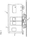
- Fig. 1 is a side view of the railroad car.
- the railroad car is made up of a railroad car structure body (hereinafter, referred to as "structure body 1"), a bogie 5, electrical components, interior equipment, and the like.
- the structure body 1 is a hexahedron including an underframe 10 (see Fig. 2 ) forming a floor surface, side structures 20 erected on both end portions in a width direction of the underframe 10, end structures 30 erected on both end portions in a longitudinal direction of the underframe 10, and a roof structure 40 supported by top end portions of the side structures 20 and top end portions of the end structures 30.
- Each side structure 20 includes window portions 22 for lighting and ventilation, a side exit/entrance 21 via which passengers and the like get on/off the railroad car, and the like.
- Both end portions in the longitudinal direction 100 of the structure body 1 are supported by the bogie 5 so as to be movable on a railway.
- Plate-shaped bolsters 14 are provided in the width direction of the underframe 10 on parts of a lower surface of the underframe forming the floor surface of the structure body 1, the parts being parts on which the bogie 5 is provided.
- the structure body 1 is elastically supported by a pair of air springs 8 (only one thereof is illustrated) provided at a center portion in the longitudinal direction 100 of a bogie frame 6 of the bogie 5 provided under the bolsters 14.
- the air springs 8 have a function of restraining vibration and the like of the bogie 5 caused by irregularity of the railway and the like from being transmitted to the structure body 1 and a function of maintaining a constant floor surface height of the structure body 1 changing in the height direction 120 in accordance with an increase and decrease in the number of passengers.
- Fig. 2 is a perspective view of the railroad car structure body seen from below.
- the underframe 10 forming the floor surface of the structure body 1 has high rigidity because the underframe 10 supports a weight of a passenger and a device provided under a floor and receives a compressive load and a tensile load from cars coupled to the own car.
- the underframe 10 includes side beams 11 that extend from the side structure 20 to both end portions in the width direction 110 and includes end sills 13 on both the end portions in the longitudinal direction 100.
- two center sills 12 are provided to extend in the longitudinal direction 100 of the underframe 10 from a center portion in the width direction 110 of the end sills 13.
- Each center sill 12 includes a coupler (not illustrated) for coupling cars.
- Each plate-shaped bolster 14 that connects one side beam 11 to the other side beam 11 is provided in the width direction 110 of the underframe 10 at a position having a predetermined distance from the end sill 13 toward the center in the longitudinal direction 100 of the underframe 10.
- the bolster 14 is connected to the side beams 11 by mechanical fastening means such as bolts at fastening portions 82a (see Fig. 3 ) on both end portions in the width direction 110 thereof and is also fastened to the two center sills 12 by mechanical fastening means such as bolts at fastening portions 82b (see Fig. 3 ) near the center in the width direction 110 thereof.
- Fig. 3 is a plan view of the bolster
- Fig. 4 is a plan view of a panel 51 constituting the bolster illustrated in Fig. 3 .
- the bolster 14 is a plate-shaped component and has a shape symmetrical to an imaginary line showing an E-E cross-section. Both the end portions in the width direction 110 of the bolster 14 serve as the fastening portions 82a on both the end portions, which are fastened to the side beams 11. Further, the fastening portions 82b near the center, which are fastened to the center sills 12, project in the longitudinal direction 100 from a center portion in the width direction 110 of the bolster 14.
- the bolster 14 in this example is made up of a core 50 made of metal and a composite material provided along this core 50. That is, at least part of a surface of the core 50 made of metal and part of a surface of the composite material exist substantially in parallel to each other.
- the core 50 is made up of the panel 51 made of metal and a center pin mounting seat 75 (see Fig. 5 ) made of metal and connected to a center portion of the panel 51.
- the bolster 14 is preferably made up of the core 50 (see Fig. 6 ) made of metal, a first composite material 33 provided on an upper surface in the height direction 120 of this core 50, and a second composite material 35 provided on a lower surface thereof.
- the above-mentioned composite materials having high tensile strength and compressive strength mainly bear the load, and therefore it is possible to promote reduction in weight of the bolster in this example and the bolster can have high bending strength and rigidity.
- the bolster 14 is preferably such that substantially the whole core 50 is wrapped in and sealed with the first composite material 33 covering the upper surface of the core 50 and the second composite material 35 covering the lower surface of the core 50 (see Fig. 6 ).
- the composite materials are a cylindrical body including the core 50 thereinside.
- the bolster in this example can have high strength, rigidity, and durability (weather resistance) of a metal component, and it is possible to provide a railway car capable of reducing a life cycle cost.
- the bolster 14 has a hybrid structure including the core 50 made of metal, the first composite material 33, and the second composite material 35. Therefore, even in a case where mechanical strength of the composite materials is lost due to degradation over time and the like, the metallic core 50 can secure residual strength, and thus the bolster 14 can have high reliability.
- the bolster 14 may be formed by inserting the core 50 through an opening of a cylindrical portion obtained by weaving fibers in a cylindrical shape, then closing this opening, impregnating this cylindrical body including the core 50 thereinside with resin, and curing the cylindrical body, instead of using the first composite material 33 and the second composite material 35.
- Fig. 4 is a plan view of the panel 51 constituting the bolster 14.
- the panel 51 is made of, for example, an aluminum alloy and includes a first member 53 having a rectangular shape and having a long side disposed in the width direction 110 at the center portion, second members 55 provided along both edges in the longitudinal direction 100 of the first member 53, third members 57 provided in the longitudinal direction 100 on both edges in the width direction 110 of the first member 53 and the second members 55, and fourth members 58 connected to the second members 55 and the third members 57.
- an integrated member in which the second members 55 and the third members 57 are integrally provided may be prepared, instead of using the second members 55 and the third members 57 which are individually prepared.
- a center portion in the width direction of the first member 53 constituting the panel 51 has an opening 61 in which the center pin mounting seat 75 (see Fig. 5 ) is provided. Further, in order to elastically support the structure body 1, openings 60 are provided on parts on which the air springs provided on an upper surface of the bogie 5 abut.
- Fig. 5 is a plan view of the center pin mounting seat 75 provided on the core illustrated in Fig. 4 .
- the center pin mounting seat 75 is, for example, a rectangular plate-shaped member that is produced by being cut off from an aluminum alloy and has a dimension in the longitudinal direction 100 larger than a dimension in the width direction 110.
- Flanges 75b provided in the longitudinal direction and flanges 75c provided in the width direction 110 are provided on a circumference of the center pin mounting seat 75.
- the center pin mounting seat 75 has an opening 75e at a center portion thereof, and a plurality of cylindrical portions 75d having axes in the height direction 120 are cut off around the opening 75e.
- the center pin mounting seat 75 is fastened to the bolster 14 by bolts to be inserted through the cylindrical portions 75d (see Fig. 9 ).
- Fig. 6 is a cross-sectional view of the bolster taken along the line A-A of Fig. 3 .
- the reference sign 50 in Fig. 6 denotes a range of the core 50.
- the core 50 in this cross-section is made up of the panel 51 including the first member 53 and the second members 55, the center pin mounting seat 75 provided on this panel 51, and the like.
- the reference sign 75 in Fig. 6 denotes a range of the center pin mounting seat 75.
- the reference sign 61 in Fig. 6 denotes an opening.
- the whole surface of the core 50 including the panel 51, the center pin mounting seat 75, and the like is sealed with the first composite material 33 and the second composite material 35 having a shell structure and divided in the height direction 120.
- Fig. 7 is a cross-sectional view of the bolster 14 taken along the line B-B of Fig. 3 .
- the bolster 14 is such that whole surfaces of the first member 53 and the second members 55 forming the core 50 are sealed with the first composite material 33 and the second composite material 35 having a shell structure and divided in the height direction 120.
- the bolster 14 has a hybrid structure in which both surfaces in a vertical direction (height direction 120) of a metallic member (core 50) disposed as a core are interposed between composite materials (first composite material 33 and second composite material 35) and is such that two composite materials (33 and 35) are separately disposed via the core 50 in the height direction 120.
- cylindrical bodies 59 penetrating in the height direction 120 are provided in the first composite material 33, the second composite material 35, and the first member 53 or the second members 55 which are part of the core 50.
- Fig. 8 is a cross-sectional view taken along the line C-C of Fig. 3 . Also in this cross-section, the bolster 14 is provided by sealing the whole surface of the assembled core 50 with the first composite material 33 and the second composite material 35 having a shell structure and divided in the height direction 120.
- Fig. 9 is a cross-sectional view of the bolster taken along the line D-D of Fig. 3 .
- the reference sign 75 in Fig. 9 denotes a range of the center pin mounting seat 75.
- the flanges 75b are fitted into openings of a face plate 53c under the first member 53.
- the whole surface is sealed with the first composite material 33 and the second composite material 35 having a shell structure, except for the cylindrical portions 75d.
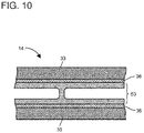
- FIG. 10 is an enlarged view of an F portion of the B-B cross-section of the bolster illustrated in Fig. 7 .
- a cross-sectional structure in Fig. 10 is a structure in which an insulating material 36 (glass fiber layer or GFRP) is provided on a surface of the core 50 (panel 51, center pin mounting seat 75, and the like) and outer sides of those insulating layers are sealed with composite materials (first composite material 33 and second composite material 35).
- an insulating material 36 glass fiber layer or GFRP
- the first composite material 33 and the second composite material 35 covering the core 50 are made of a carbon-fiber reinforced plastic (hereinafter, referred to as "CFRP") in which a carbon fiber is selected as a reinforced fiber and epoxy resin is selected as matrix resin.
- CFRP carbon-fiber reinforced plastic
- the reinforced fiber is not limited to a carbon fiber, and a glass fiber, an aramid fiber, or the like may be selected as the reinforced fiber.
- the matrix resin is not limited to epoxy resin, and unsaturated polyester resin, vinylester resin, phenol resin, or the like may be selected as the matrix resin.
- CFRP may have a quasi-isotropic laminate configuration without having an anisotropy or may have a laminate configuration having an anisotropy in order to apply strength based on a load condition (load direction) to the CFRP.
- the panel 51 forming the core 50 is produced.
- the first member 53, the second members 55, the third members 57, and the fourth members 58 forming the panel 51 are prepared.
- the first member 53 and the second members 55 are a hollow extruded shape material having two face plates 53a(55a) and 53c(55c) facing each other and a rib 53b(55b) connecting the face plates and are extruded and molded in the width direction 110.
- the panel 51 is produced by positioning four types of members, i.e., the first member 53, the second members 55, the third members 57, and the fourth members 58 and then joining those members by welding (or friction stir joining) along joining lines 71, 72, and 73.
- a part into which the center pin mounting seat 75 described below is fitted is processed in the panel 51.
- the face plate 53c under the center portion of the first member 53 (panel 51) is removed in accordance with a rectangular shape of the center pin mounting seat 75 (a rectangular shape having the dimension in the longitudinal direction 100 larger than the dimension in the width direction 110).
- a plurality of holes 80 into which the plurality of cylindrical portions 75d provided on the center pin mounting seat 75 are fitted are processed in the upper face plate 53a facing the removed lower face plate (see Fig. 3 , Fig. 4 , and Fig. 9 ).
- the center pin mounting seat 75 is shaped to have a rectangular shape having the dimension in the longitudinal direction 100 larger than the dimension in the width direction 110, and the opening 75e is processed at the center portion thereof.
- the flanges 75b provided in the longitudinal direction 100 and the flanges 75c provided in the width direction 110 are cut out on the whole circumference of the center pin mounting seat 75, and the plurality of cylindrical portions 75d to which a center pin 15 is fastened are cut out around the opening 75e so as to have an axis direction in the height direction 120.
- the center pin mounting seat 75 is connected to the panel 51 to produce the core 50.
- the center pin mounting seat 75 is fitted into the processed part of the panel 51 (first member 53).
- the flanges 75b(75c) provided on the circumference of the center pin mounting seat 75 are fitted until the flanges 75b(75c) abut on the face plate 53a of the first member 53, and the plurality of cylindrical portions 75d of the center pin mounting seat 75 are fitted into the plurality of holes 80 processed in the panel 51 (first member 53).
- superimposition of the joining lines 71 of the first member 53 and the second members 55 on the flanges 75c of the center pin mounting seat 75 is confirmed, and then the first member 53 and the center pin mounting seat 75 are welded.
- the first composite material 33 and the second composite material 35 which have been subjected to a prepreg step in which a carbon fiber is impregnated with epoxy resin in advance and then have been subjected to autoclave molding, and the core 50 are put together by being bonded with a cold-setting adhesive so as to prevent a residual stress from being generated due to a difference between linear expansion coefficients.
- the thin insulating material 36 glass fiber layer or GFRP; see Fig. 10
- the composite materials first composite material 33 and second composite material 35
- the core 50 panel 51, center pin mounting seat 75, and the like
- screws small screws
- screws may be additionally provided at intervals of several hundreds of millimeters to secure a surface pressure at the time of bonding.
- the producing method in which autoclave molding is performed after a prepreg step has been described as an example of a producing method of composite materials.
- members that have been molded by a continuous molding method such as press molding, a resin transfer molding (RTM) method, a reaction injection molding (RIM) method, or a pultrusion method may be cut in an appropriate dimension and then those members may be joined to be put together.
- RTM resin transfer molding
- RIM reaction injection molding
- pultrusion method a pultrusion method
- SCRIMP method integrally molding method in which a dispersing agent of matrix resin to be injected is disposed at the same time when a molded portion is decompressed.
- holes 81 through which the cylindrical bodies 59 (bushes; see Fig. 7 ) are inserted are machined, and then the cylindrical bodies 59 that penetrate the first composite material 33, the second composite material 35, and the core 50 in the height direction 120 to bind those members in the vertical direction are fixed. In this way, the bolster 14 is finished.
- an axial-direction dimension t1 of each cylindrical body 59 is set to be slightly larger than a dimension between the upper surface of the first composite material 33 and the lower surface of the second composite material 35.
- the cylindrical body 59 is fixed to the bolster 14 so that a top end portion of the cylindrical body 59 projects upward (direction of the underframe 10) from the upper surface of the first composite material 33 and a bottom end portion of the cylindrical body 59 projects downward from the lower surface (surface facing the railway) of the second composite material 35.
- recessed portions suitable for a shape of abutting surfaces of the cylindrical bodies 59 may be processed on parts of the side beams 11 and the center sills 12 on which the cylindrical bodies 59 (bolster 14) abut and the bolster 14 may be mechanically fastened to the side beams 11 and the center sills 12 in a state in which abutting portions of the cylindrical bodies 59 are fitted into the recessed portions provided on the side beams 11 and the center sills 12.
- the recessed portions may be provided on the side beams 11 and the center sills 12 on which all the cylindrical bodies 59 abut, or the recessed portions may be provided only on parts on which selected cylindrical bodies 59 abut.
- the recessed portions are provided on the side beams 11 and the center sills 12 in accordance with the shape of the cylindrical bodies 59 that project from the upper surface of the first composite material 33 and the surface of the second composite material 35 as described above, it is possible to maintain fastening without the bolster 14 sliding on the side beams 11 or the center sills 12 even in a case where traction force or brake force is applied to the bolster 14 from the bogie 5. Further, because the recessed portions are provided, it is possible to reduce the number of mechanical fastening portions and the number of cylindrical bodies 59, and therefore it is possible to reduce a production cost and promote reduction in weight.
- the bolster 14 is mechanically fastened to the side beams 11 and the center sills 12 constituting the underframe 10 by bolts inserted through the cylindrical bodies 59. Further, the center pin 15 is mechanically fastened to the bolster 14 by bolts inserted through the cylindrical portions 75d.
- the cylindrical bodies 59 are components provided to prevent buckling caused by a bearing surface pressure generated due to fastening force of the bolts and do not necessarily need to be made of an aluminum alloy and may be made of, for example, iron having high buckling strength.
- cylindrical bodies 59 are made of an electroconductive material, it is possible to provide a railway car having high reliability and capable of restraining an electric device from being broken or reset in a case where a current caused by a large voltage (hereinafter, surge current) is generated.
- surge current a current caused by a large voltage
- This surge current causes breakage of electric devices such as a main converter, an auxiliary power supply device, and an air conditioner mounted on the railway car and causes reset operation of those electric devices in some cases. Therefore, in order to protect the electric devices from a surge current, there is provided a grounded circuit that electrically connects the structure body 1 and the bogie 5 and is grounded on the railway (railroad) via a wheel set 7 (including wheels on both end portions of an axle) provided in the bogie 5.
- Fig. 11 is an E-E cross-sectional view (see Fig. 3 ) of the bolster constituting the underframe.
- the bolster 14 is connected to the side beams 11 and the center sills 12 constituting the underframe of the structure body 1 by mechanical fastening means such as bolts.
- the cylindrical bodies 59 (bushes) provided in the bolster 14, which are used for the above fastening, are provided in two rows or a row in the longitudinal direction 100 of the structure body 1.
- the center pin 15 serving as center of revolution of the bogie 5 is provided on a center portion in the width direction 110 of the lower surface (a surface on which the bogie 5 is provided) of the bolster 14.
- the center pin 15 and the bogie are coupled by a traction device, and traction force and brake force are transmitted to the structure body 1 from the bogie 5 via the traction device.
- the pair of air springs 8 are provided on a center portion in the longitudinal direction 100 of the bolster 14 so as to be provided in the width direction 110 thereof and interposes the center pin 15 therebetween.
- the bolster 14 in this example is not made up of only metal components.
- the first composite material 33 and the second composite material 35 are provided on both the surfaces in the vertical direction (height direction) of the plate-shaped core 50 made of metal, and therefore, even in a case where a bending load is applied to the bolster 14, the above-mentioned composite materials having high tensile strength and compressive strength mainly bear the load.
- the above-mentioned composite materials having high tensile strength and compressive strength mainly bear the load.
- it is possible to promote reduction in weight of the bolster 14 and the bolster 14 can have high bending strength and rigidity.
- the bolster 14 in this example can have high strength, rigidity, and durability (weather resistance) of a metal component, and it is possible to provide a railway car capable of reducing a life cycle cost.
- recessed portions are provided on the side beams 11 and the center sills 12 and the bolster 14 and the side beams 11 and the center sills 12 are mechanically fastened to each other in a state in which the cylindrical bodies 59 forming the bolster 14 are fitted into those recessed portions, it is possible to maintain fastening without the bolster 14 sliding on the side beams 11 or the center sills 12 even in a case where traction force or brake force is applied to the bolster 14 from the bogie 5. Furthermore, because the recessed portions are provided, it is possible to reduce the number of mechanical fastening portions and the number of cylindrical bodies 59, and therefore it is possible to reduce a production cost and promote reduction in weight.
- the bolster 14 in this example is assembled by a metallic core and composite materials with an adhesive and therefore has a high attenuation rate.
- the vibration is attenuated in a process of transmitting the vibration through the inside of the bolster 14, and therefore the vibration is hardly transmitted to the underframe 10. Accordingly, it is possible to reduce in-car noise and vibration which are generated due to vibration of the structure body 1 from the bogie 5. This makes it possible to provide a comfortable railway car.
- a state monitor system that includes an accelerometer 90 and monitors a vibration level of the bolster 14 that is in an operation state may be mounted on the upper surface (surface facing the lower surface of the underframe 10) of the bolster 14 constituting the underframe 10.
- the vibration level and a natural oscillation frequency of the bolster 14 monitored by the accelerometer 90 are changed.
- normality of the bolster 14 can be always monitored. This makes it possible to provide a railway car having high reliability.
- the bolster 14 includes a glass fiber layer (see Fig. 10 ) serving as the insulating material 36 on boundary surfaces between the core 50 made of an aluminum alloy and the composite materials (first composite material 33 and second composite material 35). With this configuration, it is possible to restrain the core 50 made of an aluminum alloy from being deteriorated due to electric corrosion. This makes it possible to provide a railway car including the bolster 14 having high reliability.
- the bolster 14 includes the electroconductive cylindrical bodies 59, and therefore it is possible to easily form the grounded circuit (see Fig. 11 ) that extends to the bogie 5 from the structure body 1 (center sills 12 and side beams 11 forming underframe 10) via the bolster 14 through those cylindrical bodies 59.
- This makes it possible to provide a railway car having high reliability and capable of restraining electric devices from being broken or reset due to a surge current.
- the invention is not limited to the above-mentioned examples and includes various modification examples.
- the above-mentioned examples have been described in detail to easily change the invention, and therefore the invention is not necessarily limited to the examples having all the configurations described above.
- a part of a configuration of an example can be replaced with another configuration, and another configuration can be added to a configuration of an example.
- a configuration can be added to, removed from, or replaced with a part of the configuration in an example.
Landscapes
- Engineering & Computer Science (AREA)
- Mechanical Engineering (AREA)
- Body Structure For Vehicles (AREA)
- Laminated Bodies (AREA)
- Electric Propulsion And Braking For Vehicles (AREA)
Abstract
Description
- The present invention relates to a plate-shaped bolster that constitutes an underframe forming a floor surface of a railway car structure body and is provided on a lower surface of the underframe in a railroad tie direction and a railway car structure body including the same.
- Generally, a railway car structure body (hereinafter, referred to as "structure body") is a hexahedron structure including an underframe forming a floor surface, side structures erected on both end portions in a width direction of the underframe, end structures erected on both end portions in a longitudinal direction of the underframe, and a roof structure provided on top end portions of the side structures and end structures. In the following production steps, a bogie for running on a railway is provided on lower surfaces of both end portions in a longitudinal direction of this structure body, and interior equipment, such as various kinds of electrical components that supply power for driving the bogie, seats, and lighting devices, is provided.
- The underframe mainly includes side beams provided in the longitudinal direction of the underframe on both the end portions in the width direction of the underframe, end sills connecting both end portions in a longitudinal direction of the side beams, bolsters provided along the end sills and separately disposed in a predetermined dimension on a center side in the longitudinal direction of the structure body, and center sills connecting the end sills and the bolsters in the longitudinal direction of the structure body and including a coupler for coupling cars.
- A center pin provided on a lower surface of each bolster forming the structure body (underframe) so as to hang downward is connected to a bogie frame forming a bogie via a traction device including a coupling link. Driving force of a railway car at the time of acceleration and brake force thereof at the time of deceleration are transmitted to the bolster of the underframe forming the structure body from the bogie via the traction device and the center pin. Therefore, the bolster needs to have high strength and rigidity.
PTL 1 discloses a railroad car structure body having the above-mentioned structure. - [PTL 1]
WO 2013/157464 - Because of a growing interest in environmental problems, reduction in life cycle energy that is a sum total of energy amounts at stages of procurement, production, use (operation), and reuse is strongly required. Reduction in weight of a structure body contributes to saving of resources and reduction in energy used at the time of operation, and therefore it is possible to reduce energy regarding use that occupies most of the life cycle energy, procurement, and production.
- Further, a shock to the railway generated when the railway car runs is alleviated because of reduction in weight, and therefore it is possible to reduce a maintenance cost of the railway.
- In order to promote reduction in weight, the structure body has been produced from a hollow extruded shape material made of an aluminum alloy. However, a current hollow extruded shape material having two face plates and a plurality of ribs connecting those face plates is thinned to near limits of an extrusion ability, and further reduction in weight is becoming difficult.
- An object of the invention is to provide a lightweight bolster having high reliability and capable of reducing a life cycle energy and a railway car structure body including this bolster.
- In order to solve the above problems, a bolster constituting an underframe of a representative railway car structure body of the invention includes: a core made of metal; and a composite material provided along the core, and the above-mentioned problems can be solved by a railway car structure body including this bolster.
- According to the invention, it is possible to provide a lightweight bolster having high reliability and capable of reducing a life cycle energy and a railway car structure body including this bolster.
- Problems, configurations, and effects other than those described above will be described by the following description of embodiments.
-
- [
Fig. 1] Fig. 1 is a side view of a railroad car. - [
Fig. 2] Fig. 2 is a perspective view of a railroad car structure body seen from below. - [
Fig. 3] Fig. 3 is a plan view of a bolster. - [
Fig. 4] Fig. 4 is a plan view of a panel constituting the bolster illustrated inFig. 3 . - [
Fig. 5] Fig. 5 is a plan view of a center pin mounting seat provided on a core illustrated inFig. 4 . - [
Fig. 6] Fig. 6 is an A-A cross-sectional view of the bolster illustrated inFig. 3 . - [
Fig. 7] Fig. 7 is a B-B cross-sectional view of the bolster illustrated inFig. 3 . - [
Fig. 8] Fig. 8 is a C-C cross-sectional view of the bolster illustrated inFig. 3 . - [
Fig. 9] Fig. 9 is a D-D cross-sectional view of the bolster illustrated inFig. 3 . - [
Fig. 10] Fig. 10 is an enlarged view of an F portion of the B-B cross-section of the bolster illustrated inFig. 7 . - [
Fig. 11] Fig. 11 is an E-E cross-sectional view (seeFig. 3 ) of the bolster constituting an underframe. - A railway car is a general term of a car operated along a laid railway and means a railroad car, a monorail car, a car for a new transportation system, a streetcar, and the like.
- Further, an example disclosed herein relates to a bolster made up of a core made of metal and a composite material provided on both upper and lower surfaces of this core and also relates to a structure body in which this bolster is provided on side beams and center sills constituting an underframe by mechanical fastening means such as rivets or bolts.
- Hereinafter, an example of the invention will be described with reference to the drawings by using a railroad car as a representative example of the railway cars.
- Note that directions regarding the railroad car for use in the following description are defined as a longitudinal direction (rail direction) 100 of the railroad car, a width direction (railroad tie direction) 110 of the railroad car, and a
height direction 120 of the railroad car crossing thelongitudinal direction 100 and thewidth direction 110. Hereinafter, those directions will be simply referred to as thelongitudinal direction 100, thewidth direction 110, and theheight direction 120. -
Fig. 1 is a side view of the railroad car. The railroad car is made up of a railroad car structure body (hereinafter, referred to as "structure body 1"), abogie 5, electrical components, interior equipment, and the like. Thestructure body 1 is a hexahedron including an underframe 10 (seeFig. 2 ) forming a floor surface,side structures 20 erected on both end portions in a width direction of theunderframe 10,end structures 30 erected on both end portions in a longitudinal direction of theunderframe 10, and aroof structure 40 supported by top end portions of theside structures 20 and top end portions of theend structures 30. Eachside structure 20 includeswindow portions 22 for lighting and ventilation, a side exit/entrance 21 via which passengers and the like get on/off the railroad car, and the like. - Both end portions in the
longitudinal direction 100 of thestructure body 1 are supported by thebogie 5 so as to be movable on a railway. Plate-shaped bolsters 14 are provided in the width direction of theunderframe 10 on parts of a lower surface of the underframe forming the floor surface of thestructure body 1, the parts being parts on which thebogie 5 is provided. Thestructure body 1 is elastically supported by a pair of air springs 8 (only one thereof is illustrated) provided at a center portion in thelongitudinal direction 100 of a bogie frame 6 of thebogie 5 provided under thebolsters 14. Theair springs 8 have a function of restraining vibration and the like of thebogie 5 caused by irregularity of the railway and the like from being transmitted to thestructure body 1 and a function of maintaining a constant floor surface height of thestructure body 1 changing in theheight direction 120 in accordance with an increase and decrease in the number of passengers. -
Fig. 2 is a perspective view of the railroad car structure body seen from below. Theunderframe 10 forming the floor surface of thestructure body 1 has high rigidity because theunderframe 10 supports a weight of a passenger and a device provided under a floor and receives a compressive load and a tensile load from cars coupled to the own car. Theunderframe 10 includesside beams 11 that extend from theside structure 20 to both end portions in thewidth direction 110 and includesend sills 13 on both the end portions in thelongitudinal direction 100. Further, twocenter sills 12 are provided to extend in thelongitudinal direction 100 of theunderframe 10 from a center portion in thewidth direction 110 of theend sills 13. Eachcenter sill 12 includes a coupler (not illustrated) for coupling cars. - Each plate-
shaped bolster 14 that connects oneside beam 11 to theother side beam 11 is provided in thewidth direction 110 of theunderframe 10 at a position having a predetermined distance from theend sill 13 toward the center in thelongitudinal direction 100 of theunderframe 10. Thebolster 14 is connected to theside beams 11 by mechanical fastening means such as bolts at fasteningportions 82a (seeFig. 3 ) on both end portions in thewidth direction 110 thereof and is also fastened to the twocenter sills 12 by mechanical fastening means such as bolts at fasteningportions 82b (seeFig. 3 ) near the center in thewidth direction 110 thereof. -
Fig. 3 is a plan view of the bolster, andFig. 4 is a plan view of apanel 51 constituting the bolster illustrated inFig. 3 . Thebolster 14 is a plate-shaped component and has a shape symmetrical to an imaginary line showing an E-E cross-section. Both the end portions in thewidth direction 110 of thebolster 14 serve as the fasteningportions 82a on both the end portions, which are fastened to theside beams 11. Further, the fasteningportions 82b near the center, which are fastened to thecenter sills 12, project in thelongitudinal direction 100 from a center portion in thewidth direction 110 of thebolster 14. - The
bolster 14 in this example is made up of acore 50 made of metal and a composite material provided along thiscore 50. That is, at least part of a surface of thecore 50 made of metal and part of a surface of the composite material exist substantially in parallel to each other. Thecore 50 is made up of thepanel 51 made of metal and a center pin mounting seat 75 (seeFig. 5 ) made of metal and connected to a center portion of thepanel 51. - With such a configuration, it is possible to promote reduction in weight of the bolster in this example, as compared to a conventional bolster made up of only metal components.
- Further, the bolster 14 is preferably made up of the core 50 (see
Fig. 6 ) made of metal, a firstcomposite material 33 provided on an upper surface in theheight direction 120 of thiscore 50, and a secondcomposite material 35 provided on a lower surface thereof. - With such a configuration, even in a case where a bending load is applied to the bolster 14, the above-mentioned composite materials having high tensile strength and compressive strength mainly bear the load, and therefore it is possible to promote reduction in weight of the bolster in this example and the bolster can have high bending strength and rigidity.
- Further, the bolster 14 is preferably such that substantially the
whole core 50 is wrapped in and sealed with the firstcomposite material 33 covering the upper surface of thecore 50 and the secondcomposite material 35 covering the lower surface of the core 50 (seeFig. 6 ). In other words, the composite materials are a cylindrical body including the core 50 thereinside. - With such a configuration, the bolster in this example can have high strength, rigidity, and durability (weather resistance) of a metal component, and it is possible to provide a railway car capable of reducing a life cycle cost.
- Further, the bolster 14 has a hybrid structure including the core 50 made of metal, the first
composite material 33, and the secondcomposite material 35. Therefore, even in a case where mechanical strength of the composite materials is lost due to degradation over time and the like, themetallic core 50 can secure residual strength, and thus the bolster 14 can have high reliability. - Note that, although not illustrated, the bolster 14 may be formed by inserting the core 50 through an opening of a cylindrical portion obtained by weaving fibers in a cylindrical shape, then closing this opening, impregnating this cylindrical body including the core 50 thereinside with resin, and curing the cylindrical body, instead of using the first
composite material 33 and the secondcomposite material 35. -
Fig. 4 is a plan view of thepanel 51 constituting the bolster 14. Thepanel 51 is made of, for example, an aluminum alloy and includes afirst member 53 having a rectangular shape and having a long side disposed in thewidth direction 110 at the center portion,second members 55 provided along both edges in thelongitudinal direction 100 of thefirst member 53,third members 57 provided in thelongitudinal direction 100 on both edges in thewidth direction 110 of thefirst member 53 and thesecond members 55, andfourth members 58 connected to thesecond members 55 and thethird members 57. Note that an integrated member in which thesecond members 55 and thethird members 57 are integrally provided may be prepared, instead of using thesecond members 55 and thethird members 57 which are individually prepared. - A center portion in the width direction of the
first member 53 constituting thepanel 51 has anopening 61 in which the center pin mounting seat 75 (seeFig. 5 ) is provided. Further, in order to elastically support thestructure body 1,openings 60 are provided on parts on which the air springs provided on an upper surface of thebogie 5 abut. -
Fig. 5 is a plan view of the centerpin mounting seat 75 provided on the core illustrated inFig. 4 . The centerpin mounting seat 75 is, for example, a rectangular plate-shaped member that is produced by being cut off from an aluminum alloy and has a dimension in thelongitudinal direction 100 larger than a dimension in thewidth direction 110.Flanges 75b provided in the longitudinal direction andflanges 75c provided in thewidth direction 110 are provided on a circumference of the centerpin mounting seat 75. - The center
pin mounting seat 75 has anopening 75e at a center portion thereof, and a plurality ofcylindrical portions 75d having axes in theheight direction 120 are cut off around theopening 75e. The centerpin mounting seat 75 is fastened to the bolster 14 by bolts to be inserted through thecylindrical portions 75d (seeFig. 9 ). -
Fig. 6 is a cross-sectional view of the bolster taken along the line A-A ofFig. 3 . Thereference sign 50 inFig. 6 denotes a range of thecore 50. The core 50 in this cross-section is made up of thepanel 51 including thefirst member 53 and thesecond members 55, the centerpin mounting seat 75 provided on thispanel 51, and the like. In addition, thereference sign 75 inFig. 6 denotes a range of the centerpin mounting seat 75. Further, thereference sign 61 inFig. 6 denotes an opening. - Further, the whole surface of the core 50 including the
panel 51, the centerpin mounting seat 75, and the like is sealed with the firstcomposite material 33 and the secondcomposite material 35 having a shell structure and divided in theheight direction 120. -
Fig. 7 is a cross-sectional view of the bolster 14 taken along the line B-B ofFig. 3 . In this cross-section, the bolster 14 is such that whole surfaces of thefirst member 53 and thesecond members 55 forming the core 50 are sealed with the firstcomposite material 33 and the secondcomposite material 35 having a shell structure and divided in theheight direction 120. - In other words, the bolster 14 has a hybrid structure in which both surfaces in a vertical direction (height direction 120) of a metallic member (core 50) disposed as a core are interposed between composite materials (first
composite material 33 and second composite material 35) and is such that two composite materials (33 and 35) are separately disposed via thecore 50 in theheight direction 120. - Further,
cylindrical bodies 59 penetrating in theheight direction 120 are provided in the firstcomposite material 33, the secondcomposite material 35, and thefirst member 53 or thesecond members 55 which are part of thecore 50. -
Fig. 8 is a cross-sectional view taken along the line C-C ofFig. 3 . Also in this cross-section, the bolster 14 is provided by sealing the whole surface of the assembledcore 50 with the firstcomposite material 33 and the secondcomposite material 35 having a shell structure and divided in theheight direction 120. -
Fig. 9 is a cross-sectional view of the bolster taken along the line D-D ofFig. 3 . Thereference sign 75 inFig. 9 denotes a range of the centerpin mounting seat 75. In the centerpin mounting seat 75, theflanges 75b are fitted into openings of aface plate 53c under thefirst member 53. In addition, as well as in other cross-sectional views, the whole surface is sealed with the firstcomposite material 33 and the secondcomposite material 35 having a shell structure, except for thecylindrical portions 75d. -
Fig. 10 is an enlarged view of an F portion of the B-B cross-section of the bolster illustrated inFig. 7 . A cross-sectional structure inFig. 10 is a structure in which an insulating material 36 (glass fiber layer or GFRP) is provided on a surface of the core 50 (panel 51, centerpin mounting seat 75, and the like) and outer sides of those insulating layers are sealed with composite materials (firstcomposite material 33 and second composite material 35). - With this configuration, it is possible to restrain the core 50 made of an aluminum alloy from being deteriorated due to electric corrosion. This makes it possible to provide a railway car including the bolster 14 having high reliability.
- Next, the first
composite material 33 and the secondcomposite material 35 covering thecore 50 will be described. The firstcomposite material 33 and the secondcomposite material 35 are made of a carbon-fiber reinforced plastic (hereinafter, referred to as "CFRP") in which a carbon fiber is selected as a reinforced fiber and epoxy resin is selected as matrix resin. Note that the reinforced fiber is not limited to a carbon fiber, and a glass fiber, an aramid fiber, or the like may be selected as the reinforced fiber. Similarly, the matrix resin is not limited to epoxy resin, and unsaturated polyester resin, vinylester resin, phenol resin, or the like may be selected as the matrix resin. - Further, in order to equalize an elastic modulus of CFRP with that of the core made of an aluminum alloy, CFRP may have a quasi-isotropic laminate configuration without having an anisotropy or may have a laminate configuration having an anisotropy in order to apply strength based on a load condition (load direction) to the CFRP.
- Hereinafter, production steps of the bolster 14 will be described. First, the
panel 51 forming thecore 50 is produced. Thefirst member 53, thesecond members 55, thethird members 57, and thefourth members 58 forming thepanel 51 are prepared. - The
first member 53 and thesecond members 55 are a hollow extruded shape material having twoface plates 53a(55a) and 53c(55c) facing each other and arib 53b(55b) connecting the face plates and are extruded and molded in thewidth direction 110. Thepanel 51 is produced by positioning four types of members, i.e., thefirst member 53, thesecond members 55, thethird members 57, and thefourth members 58 and then joining those members by welding (or friction stir joining) along joininglines - Then, a part into which the center
pin mounting seat 75 described below is fitted is processed in thepanel 51. Theface plate 53c under the center portion of the first member 53 (panel 51) is removed in accordance with a rectangular shape of the center pin mounting seat 75 (a rectangular shape having the dimension in thelongitudinal direction 100 larger than the dimension in the width direction 110). Further, a plurality ofholes 80 into which the plurality ofcylindrical portions 75d provided on the centerpin mounting seat 75 are fitted are processed in theupper face plate 53a facing the removed lower face plate (seeFig. 3 ,Fig. 4 , andFig. 9 ). - Next, an aluminum alloy is cut out to produce the center
pin mounting seat 75. The centerpin mounting seat 75 is shaped to have a rectangular shape having the dimension in thelongitudinal direction 100 larger than the dimension in thewidth direction 110, and theopening 75e is processed at the center portion thereof. Theflanges 75b provided in thelongitudinal direction 100 and theflanges 75c provided in thewidth direction 110 are cut out on the whole circumference of the centerpin mounting seat 75, and the plurality ofcylindrical portions 75d to which acenter pin 15 is fastened are cut out around theopening 75e so as to have an axis direction in theheight direction 120. - Then, the center
pin mounting seat 75 is connected to thepanel 51 to produce thecore 50. First, the centerpin mounting seat 75 is fitted into the processed part of the panel 51 (first member 53). Theflanges 75b(75c) provided on the circumference of the centerpin mounting seat 75 are fitted until theflanges 75b(75c) abut on theface plate 53a of thefirst member 53, and the plurality ofcylindrical portions 75d of the centerpin mounting seat 75 are fitted into the plurality ofholes 80 processed in the panel 51 (first member 53). At this time, superimposition of the joininglines 71 of thefirst member 53 and thesecond members 55 on theflanges 75c of the centerpin mounting seat 75 is confirmed, and then thefirst member 53 and the centerpin mounting seat 75 are welded. By performing attachment as described above, it is possible to firmly fix the centerpin mounting seat 75 to thepanel 51. - Next, the first
composite material 33 and the secondcomposite material 35, which have been subjected to a prepreg step in which a carbon fiber is impregnated with epoxy resin in advance and then have been subjected to autoclave molding, and the core 50 are put together by being bonded with a cold-setting adhesive so as to prevent a residual stress from being generated due to a difference between linear expansion coefficients. At this time, the thin insulating material 36 (glass fiber layer or GFRP; seeFig. 10 ) which achieves electrical insulation to restrain electric corrosion is provided on the surfaces of the composite materials (firstcomposite material 33 and second composite material 35) which are in contact with the core 50 (panel 51, centerpin mounting seat 75, and the like) made of an aluminum alloy. Further, in order to obtain a firm bonding surface, screws (small screws) and the like may be additionally provided at intervals of several hundreds of millimeters to secure a surface pressure at the time of bonding. - Note that the producing method in which autoclave molding is performed after a prepreg step has been described as an example of a producing method of composite materials. However, instead of this producing method, members that have been molded by a continuous molding method such as press molding, a resin transfer molding (RTM) method, a reaction injection molding (RIM) method, or a pultrusion method may be cut in an appropriate dimension and then those members may be joined to be put together. Further, there may also be employed, for example, an integrally molding method (SCRIMP method) in which a dispersing agent of matrix resin to be injected is disposed at the same time when a molded portion is decompressed.
- After assembly is completed, holes 81 through which the cylindrical bodies 59 (bushes; see
Fig. 7 ) are inserted are machined, and then thecylindrical bodies 59 that penetrate the firstcomposite material 33, the secondcomposite material 35, and the core 50 in theheight direction 120 to bind those members in the vertical direction are fixed. In this way, the bolster 14 is finished. - As illustrated in
Fig. 7 , an axial-direction dimension t1 of eachcylindrical body 59 is set to be slightly larger than a dimension between the upper surface of the firstcomposite material 33 and the lower surface of the secondcomposite material 35. Thecylindrical body 59 is fixed to the bolster 14 so that a top end portion of thecylindrical body 59 projects upward (direction of the underframe 10) from the upper surface of the firstcomposite material 33 and a bottom end portion of thecylindrical body 59 projects downward from the lower surface (surface facing the railway) of the secondcomposite material 35. - Further, although not illustrated, recessed portions suitable for a shape of abutting surfaces of the
cylindrical bodies 59 may be processed on parts of the side beams 11 and thecenter sills 12 on which the cylindrical bodies 59 (bolster 14) abut and the bolster 14 may be mechanically fastened to the side beams 11 and thecenter sills 12 in a state in which abutting portions of thecylindrical bodies 59 are fitted into the recessed portions provided on the side beams 11 and thecenter sills 12. - Note that the recessed portions may be provided on the side beams 11 and the
center sills 12 on which all thecylindrical bodies 59 abut, or the recessed portions may be provided only on parts on which selectedcylindrical bodies 59 abut. - When the recessed portions are provided on the side beams 11 and the
center sills 12 in accordance with the shape of thecylindrical bodies 59 that project from the upper surface of the firstcomposite material 33 and the surface of the secondcomposite material 35 as described above, it is possible to maintain fastening without the bolster 14 sliding on the side beams 11 or thecenter sills 12 even in a case where traction force or brake force is applied to the bolster 14 from thebogie 5. Further, because the recessed portions are provided, it is possible to reduce the number of mechanical fastening portions and the number ofcylindrical bodies 59, and therefore it is possible to reduce a production cost and promote reduction in weight. - The bolster 14 is mechanically fastened to the side beams 11 and the
center sills 12 constituting theunderframe 10 by bolts inserted through thecylindrical bodies 59. Further, thecenter pin 15 is mechanically fastened to the bolster 14 by bolts inserted through thecylindrical portions 75d. Thecylindrical bodies 59 are components provided to prevent buckling caused by a bearing surface pressure generated due to fastening force of the bolts and do not necessarily need to be made of an aluminum alloy and may be made of, for example, iron having high buckling strength. - Further, when the
cylindrical bodies 59 are made of an electroconductive material, it is possible to provide a railway car having high reliability and capable of restraining an electric device from being broken or reset in a case where a current caused by a large voltage (hereinafter, surge current) is generated. - For example, when a power collector (pantograph) is brought into contact with an overhead line or is separated from the overhead line or when a vacuum circuit breaker (VCB) provided in a circuit connecting the power collector and a main transformer is switched on/off, an extremely large voltage is momentarily generated and a surge current is generated due to this large voltage in some cases.
- This surge current causes breakage of electric devices such as a main converter, an auxiliary power supply device, and an air conditioner mounted on the railway car and causes reset operation of those electric devices in some cases. Therefore, in order to protect the electric devices from a surge current, there is provided a grounded circuit that electrically connects the
structure body 1 and thebogie 5 and is grounded on the railway (railroad) via a wheel set 7 (including wheels on both end portions of an axle) provided in thebogie 5. - In other words, by providing an electroconductive or high electroconductive member that penetrates the upper surface and lower surface in the
height direction 120 of the bolster covered with the composite materials, it is possible to form a grounded circuit (seeFig. 11 ) that extends to thebogie 5 from the structure body 1 (thecenter sills 12 and the side beams 11 forming the underframe 10) via the bolster 14. Therefore, even when the bolster 14 is covered with composite materials having lower electroconductivity than that of a metal or the like, it is possible to provide a railway car having high reliability and capable of restraining electric devices from being broken or reset due to a surge current. -
Fig. 11 is an E-E cross-sectional view (seeFig. 3 ) of the bolster constituting the underframe. The bolster 14 is connected to the side beams 11 and thecenter sills 12 constituting the underframe of thestructure body 1 by mechanical fastening means such as bolts. The cylindrical bodies 59 (bushes) provided in the bolster 14, which are used for the above fastening, are provided in two rows or a row in thelongitudinal direction 100 of thestructure body 1. - The
center pin 15 serving as center of revolution of thebogie 5 is provided on a center portion in thewidth direction 110 of the lower surface (a surface on which thebogie 5 is provided) of the bolster 14. Thecenter pin 15 and the bogie are coupled by a traction device, and traction force and brake force are transmitted to thestructure body 1 from thebogie 5 via the traction device. Further, the pair of air springs 8 are provided on a center portion in thelongitudinal direction 100 of the bolster 14 so as to be provided in thewidth direction 110 thereof and interposes thecenter pin 15 therebetween. - A sufficient space exists between the lower surface of the
underframe 10 and the upper surface of the bolster 14, and a piping (wiring) module 9 obtained by bundling a plurality of wires and pipes is provided on the lower surface of theunderframe 10 in thelongitudinal direction 100 of thestructure body 1 from end portions thereof to a center portion thereof without interfering with the bolster 14. Further, an air tank may also be provided in the above-mentioned space. - As described above, by employing the configuration in this example, it is possible to promote reduction in weight of the bolster 14 because the bolster 14 in this example is not made up of only metal components. Further, because the first
composite material 33 and the secondcomposite material 35 are provided on both the surfaces in the vertical direction (height direction) of the plate-shapedcore 50 made of metal, and therefore, even in a case where a bending load is applied to the bolster 14, the above-mentioned composite materials having high tensile strength and compressive strength mainly bear the load. Thus, it is possible to promote reduction in weight of the bolster 14 and the bolster 14 can have high bending strength and rigidity. - Further, because both the whole surfaces in the vertical direction (height direction) of the plate-shaped
core 50 made of metal is sealed with the firstcomposite material 33 and the secondcomposite material 35, the bolster 14 in this example can have high strength, rigidity, and durability (weather resistance) of a metal component, and it is possible to provide a railway car capable of reducing a life cycle cost. - Further, the bolster 14 in this example has a hybrid structure including the core 50 made of metal, the first
composite material 33, and the secondcomposite material 35. Therefore, even in a case where mechanical strength of the composite materials is lost due to degradation over time and the like, themetallic core 50 can secure residual strength, and thus the bolster 14 can have high reliability. - Further, with the configuration in which recessed portions are provided on the side beams 11 and the
center sills 12 and the bolster 14 and the side beams 11 and thecenter sills 12 are mechanically fastened to each other in a state in which thecylindrical bodies 59 forming the bolster 14 are fitted into those recessed portions, it is possible to maintain fastening without the bolster 14 sliding on the side beams 11 or thecenter sills 12 even in a case where traction force or brake force is applied to the bolster 14 from thebogie 5. Furthermore, because the recessed portions are provided, it is possible to reduce the number of mechanical fastening portions and the number ofcylindrical bodies 59, and therefore it is possible to reduce a production cost and promote reduction in weight. - Further, the bolster 14 in this example is assembled by a metallic core and composite materials with an adhesive and therefore has a high attenuation rate. Thus, when vibration is input to the bolster 14 from the
bogie 5 via the traction device and thecenter pin 15, the vibration is attenuated in a process of transmitting the vibration through the inside of the bolster 14, and therefore the vibration is hardly transmitted to theunderframe 10. Accordingly, it is possible to reduce in-car noise and vibration which are generated due to vibration of thestructure body 1 from thebogie 5. This makes it possible to provide a comfortable railway car. - Further, as a modification example of this example, a state monitor system that includes an
accelerometer 90 and monitors a vibration level of the bolster 14 that is in an operation state may be mounted on the upper surface (surface facing the lower surface of the underframe 10) of the bolster 14 constituting theunderframe 10. When the first (second) composite material 33(35) constituting the bolster 14 is deteriorated or bonding surfaces of thecore 50 and the composite materials constituting the bolster 14 are peeled off, the vibration level and a natural oscillation frequency of the bolster 14 monitored by theaccelerometer 90 are changed. By monitoring those changes in the vibration level and the like, normality of the bolster 14 can be always monitored. This makes it possible to provide a railway car having high reliability. - Further, the bolster 14 includes a glass fiber layer (see
Fig. 10 ) serving as the insulatingmaterial 36 on boundary surfaces between the core 50 made of an aluminum alloy and the composite materials (firstcomposite material 33 and second composite material 35). With this configuration, it is possible to restrain the core 50 made of an aluminum alloy from being deteriorated due to electric corrosion. This makes it possible to provide a railway car including the bolster 14 having high reliability. - Further, the bolster 14 includes the electroconductive
cylindrical bodies 59, and therefore it is possible to easily form the grounded circuit (seeFig. 11 ) that extends to thebogie 5 from the structure body 1 (center sills 12 andside beams 11 forming underframe 10) via the bolster 14 through thosecylindrical bodies 59. This makes it possible to provide a railway car having high reliability and capable of restraining electric devices from being broken or reset due to a surge current. - With the above configuration, it is possible to provide a lightweight bolster having high reliability and capable of reducing a life cycle energy and a railway car structure body including this bolster.
- Note that the invention is not limited to the above-mentioned examples and includes various modification examples. For example, the above-mentioned examples have been described in detail to easily change the invention, and therefore the invention is not necessarily limited to the examples having all the configurations described above. Further, a part of a configuration of an example can be replaced with another configuration, and another configuration can be added to a configuration of an example. Further, a configuration can be added to, removed from, or replaced with a part of the configuration in an example.
-
- 1 ... structure body
- 5 ... bogie
- 6 ... bogie frame
- 7 ... wheel set
- 8 ... air spring
- 9 ... piping (wiring) module
- 10 ... underframe
- 11 ... side beam
- 12 ... center sill
- 13 ... end sill
- 14 ... bolster
- 15 ... center pin
- 20 ... side structure
- 21 ... side exit/entrance
- 22 ... window portion
- 50 ... core
- 30 ... end structure
- 40 ... roof structure
- 33 ... first composite material
- 35 ... second composite material
- 36 ... insulating material
- 51 ... panel
- 53 ... first member
- 55 ... second member
- 57 ... third member
- 58 ... fourth member
- 59 ... cylindrical body
- 60, 61 ... opening
- 71, 72, 73 ... joining line
- 75 ... center pin mounting seat
- 75b, 75c ... flange
- 75d ... cylindrical portion
- 75e ... opening
- 80, 81 ... hole
- 82a, 82b ... fastening portion
- 90 ... accelerometer
- 100 ... longitudinal direction
- 110 ... width direction
- 120 ... height direction
Claims (12)
- A bolster forming an underframe of a railway car structure body, the bolster comprising:a core made of metal; anda composite material provided along the core.
- The bolster according to claim 1, wherein
the composite material is a cylindrical body including the core. - The bolster according to claim 1, wherein
the composite material includes
a first composite material provided on an upper surface of the core, and
a second composite material provided on a lower surface of the core. - The bolster according to claim 3, further comprising
an electroconductive member penetrating the first composite material, the core, and the second composite material in a height direction of the railway car structure body. - The bolster according to claim 4, wherein
the core includes
a panel made of metal, and
a center pin mounting seat provided on a center portion of the panel. - The bolster according to claim 5, wherein
the panel is an extruded shape material made of an aluminum alloy and having two face plates facing each other and a rib connecting the face plates. - The bolster according to claim 5, wherein
the panel includes
a first member provided in a width direction on a center portion in a longitudinal direction of the bolster, and
second members joined to the first member along both end portions in a longitudinal direction of the first member. - The bolster according to claim 5, wherein
the center pin mounting seat
is a rectangular plate-shaped member having a dimension in a longitudinal direction larger than a dimension in a width direction, and
has a flange to abut on and be welded to one of the face plates on a circumference of the plate-shaped member and a plurality of cylindrical portions through which bolts for fixing the center pin to the center pin mounting seat are inserted. - The bolster according to claim 8, wherein
the center pin mounting seat is welded to the panel so that the flange is superimposed on a joining line. - The bolster according to claim 4, wherein
the bolster includes an insulating material on boundary surfaces between the core and the first composite material and the second composite material. - The bolster according to claim 4, wherein
the electroconductive member has a cylindrical body, and a top end portion of the electroconductive member projects from an upper surface of the first composite material. - A railway car structure body, comprising
the bolster according to any one of claims 1 to 11.
Applications Claiming Priority (1)
| Application Number | Priority Date | Filing Date | Title |
|---|---|---|---|
| PCT/JP2015/085374 WO2017104052A1 (en) | 2015-12-17 | 2015-12-17 | Body bolster and railroad vehicle structure provided with same |
Publications (3)
| Publication Number | Publication Date |
|---|---|
| EP3392118A1 true EP3392118A1 (en) | 2018-10-24 |
| EP3392118A4 EP3392118A4 (en) | 2019-08-28 |
| EP3392118B1 EP3392118B1 (en) | 2021-06-02 |
Family
ID=59056226
Family Applications (1)
| Application Number | Title | Priority Date | Filing Date |
|---|---|---|---|
| EP15910742.4A Active EP3392118B1 (en) | 2015-12-17 | 2015-12-17 | Body bolster and railroad vehicle structure provided with same |
Country Status (3)
| Country | Link |
|---|---|
| EP (1) | EP3392118B1 (en) |
| JP (1) | JP6535757B2 (en) |
| WO (1) | WO2017104052A1 (en) |
Families Citing this family (3)
| Publication number | Priority date | Publication date | Assignee | Title |
|---|---|---|---|---|
| EP3865368B1 (en) * | 2018-10-11 | 2022-11-23 | Hitachi, Ltd. | Rail vehicle underframe structure and rail vehicle |
| JP6823631B2 (en) * | 2018-10-12 | 2021-02-03 | 株式会社日立製作所 | Rail vehicle structure |
| CN113619626B (en) * | 2021-08-20 | 2023-01-24 | 中车唐山机车车辆有限公司 | Vehicle body and magnetic levitation vehicle |
Family Cites Families (5)
| Publication number | Priority date | Publication date | Assignee | Title |
|---|---|---|---|---|
| JPH04292258A (en) * | 1991-03-20 | 1992-10-16 | Hitachi Ltd | Framed structure used with fiber reinforced plastic composite material |
| JPH0717398A (en) * | 1993-06-30 | 1995-01-20 | Hitachi Ltd | Undercarriage of railway vehicle |
| AU734375B2 (en) * | 1997-08-21 | 2001-06-14 | Toray Industries, Inc. | Light metal/CFRP-made structural members |
| JP5685494B2 (en) * | 2011-06-14 | 2015-03-18 | 株式会社日立製作所 | Railway vehicle body structure with wiring and piping modules |
| FR3009262B1 (en) * | 2013-08-02 | 2015-09-18 | Astrium Sas | STRUCTURE IN COMPOSITE MATERIALS FOR WAGON CHASSIS |
-
2015
- 2015-12-17 JP JP2017556279A patent/JP6535757B2/en active Active
- 2015-12-17 EP EP15910742.4A patent/EP3392118B1/en active Active
- 2015-12-17 WO PCT/JP2015/085374 patent/WO2017104052A1/en not_active Ceased
Also Published As
| Publication number | Publication date |
|---|---|
| JPWO2017104052A1 (en) | 2018-09-06 |
| EP3392118B1 (en) | 2021-06-02 |
| JP6535757B2 (en) | 2019-06-26 |
| EP3392118A4 (en) | 2019-08-28 |
| WO2017104052A1 (en) | 2017-06-22 |
Similar Documents
| Publication | Publication Date | Title |
|---|---|---|
| EP3392118B1 (en) | Body bolster and railroad vehicle structure provided with same | |
| CN114194242B (en) | Rail train bogie frame structure and forming method | |
| JP2013071469A (en) | Railroad vehicle structure, and method for manufacturing the same | |
| CN112644550B (en) | Steering frame | |
| CN101624055B (en) | Frame car body structure of magnetic levitation type rail polling car | |
| JP2016530152A (en) | Composite material structure for rail car chassis | |
| JP2017532255A (en) | Vehicle face wall structures such as train vehicles made from sandwich composite materials | |
| CN105235697A (en) | Train body structure of magnetic suspension train | |
| CN110312653A (en) | Cross member with load distribution element for receiving pivot pin | |
| US5303657A (en) | Bogie frame of rolling stock having composite hollow beam construction | |
| KR101231835B1 (en) | one-piece braking and traction equipment for composite bogie frame | |
| EP4219264B1 (en) | Frame structure for a bogie | |
| US20250171057A1 (en) | Rail vehicle | |
| WO1993019965A1 (en) | Railway vehicle of modular construction | |
| JP2010254122A (en) | Track system traffic vehicle | |
| CN110312651A (en) | Rail vehicle collision system | |
| CN110291000B (en) | Rail vehicle head module | |
| CN113022610B (en) | Floor composition for magnetic levitation vehicle and magnetic levitation vehicle | |
| JP2010254123A (en) | Joint structure | |
| JP5466114B2 (en) | Railway vehicle structure | |
| CN112644548B (en) | Framework of bogie | |
| CN112644546B (en) | Framework of bogie | |
| CN112644543B (en) | Steering frame | |
| CN112644545B (en) | Framework of bogie | |
| CN115485178B (en) | Device for transmitting longitudinal forces on rail vehicles |
Legal Events
| Date | Code | Title | Description |
|---|---|---|---|
| STAA | Information on the status of an ep patent application or granted ep patent |
Free format text: STATUS: THE INTERNATIONAL PUBLICATION HAS BEEN MADE |
|
| PUAI | Public reference made under article 153(3) epc to a published international application that has entered the european phase |
Free format text: ORIGINAL CODE: 0009012 |
|
| STAA | Information on the status of an ep patent application or granted ep patent |
Free format text: STATUS: REQUEST FOR EXAMINATION WAS MADE |
|
| 17P | Request for examination filed |
Effective date: 20180523 |
|
| AK | Designated contracting states |
Kind code of ref document: A1 Designated state(s): AL AT BE BG CH CY CZ DE DK EE ES FI FR GB GR HR HU IE IS IT LI LT LU LV MC MK MT NL NO PL PT RO RS SE SI SK SM TR |
|
| AX | Request for extension of the european patent |
Extension state: BA ME |
|
| DAV | Request for validation of the european patent (deleted) | ||
| DAX | Request for extension of the european patent (deleted) | ||
| A4 | Supplementary search report drawn up and despatched |
Effective date: 20190725 |
|
| RIC1 | Information provided on ipc code assigned before grant |
Ipc: B61F 1/12 20060101AFI20190719BHEP |
|
| GRAP | Despatch of communication of intention to grant a patent |
Free format text: ORIGINAL CODE: EPIDOSNIGR1 |
|
| STAA | Information on the status of an ep patent application or granted ep patent |
Free format text: STATUS: GRANT OF PATENT IS INTENDED |
|
| INTG | Intention to grant announced |
Effective date: 20210120 |
|
| GRAS | Grant fee paid |
Free format text: ORIGINAL CODE: EPIDOSNIGR3 |
|
| GRAA | (expected) grant |
Free format text: ORIGINAL CODE: 0009210 |
|
| STAA | Information on the status of an ep patent application or granted ep patent |
Free format text: STATUS: THE PATENT HAS BEEN GRANTED |
|
| REG | Reference to a national code |
Ref country code: CH Ref legal event code: EP |
|
| AK | Designated contracting states |
Kind code of ref document: B1 Designated state(s): AL AT BE BG CH CY CZ DE DK EE ES FI FR GB GR HR HU IE IS IT LI LT LU LV MC MK MT NL NO PL PT RO RS SE SI SK SM TR |
|
| REG | Reference to a national code |
Ref country code: GB Ref legal event code: FG4D |
|
| REG | Reference to a national code |
Ref country code: AT Ref legal event code: REF Ref document number: 1398195 Country of ref document: AT Kind code of ref document: T Effective date: 20210615 |
|
| REG | Reference to a national code |
Ref country code: IE Ref legal event code: FG4D |
|
| REG | Reference to a national code |
Ref country code: DE Ref legal event code: R096 Ref document number: 602015070143 Country of ref document: DE |
|
| REG | Reference to a national code |
Ref country code: LT Ref legal event code: MG9D |
|
| PG25 | Lapsed in a contracting state [announced via postgrant information from national office to epo] |
Ref country code: HR Free format text: LAPSE BECAUSE OF FAILURE TO SUBMIT A TRANSLATION OF THE DESCRIPTION OR TO PAY THE FEE WITHIN THE PRESCRIBED TIME-LIMIT Effective date: 20210602 Ref country code: BG Free format text: LAPSE BECAUSE OF FAILURE TO SUBMIT A TRANSLATION OF THE DESCRIPTION OR TO PAY THE FEE WITHIN THE PRESCRIBED TIME-LIMIT Effective date: 20210902 Ref country code: FI Free format text: LAPSE BECAUSE OF FAILURE TO SUBMIT A TRANSLATION OF THE DESCRIPTION OR TO PAY THE FEE WITHIN THE PRESCRIBED TIME-LIMIT Effective date: 20210602 Ref country code: LT Free format text: LAPSE BECAUSE OF FAILURE TO SUBMIT A TRANSLATION OF THE DESCRIPTION OR TO PAY THE FEE WITHIN THE PRESCRIBED TIME-LIMIT Effective date: 20210602 |
|
| REG | Reference to a national code |
Ref country code: NL Ref legal event code: MP Effective date: 20210602 |
|
| REG | Reference to a national code |
Ref country code: AT Ref legal event code: MK05 Ref document number: 1398195 Country of ref document: AT Kind code of ref document: T Effective date: 20210602 |
|
| PG25 | Lapsed in a contracting state [announced via postgrant information from national office to epo] |
Ref country code: GR Free format text: LAPSE BECAUSE OF FAILURE TO SUBMIT A TRANSLATION OF THE DESCRIPTION OR TO PAY THE FEE WITHIN THE PRESCRIBED TIME-LIMIT Effective date: 20210903 Ref country code: LV Free format text: LAPSE BECAUSE OF FAILURE TO SUBMIT A TRANSLATION OF THE DESCRIPTION OR TO PAY THE FEE WITHIN THE PRESCRIBED TIME-LIMIT Effective date: 20210602 Ref country code: SE Free format text: LAPSE BECAUSE OF FAILURE TO SUBMIT A TRANSLATION OF THE DESCRIPTION OR TO PAY THE FEE WITHIN THE PRESCRIBED TIME-LIMIT Effective date: 20210602 Ref country code: RS Free format text: LAPSE BECAUSE OF FAILURE TO SUBMIT A TRANSLATION OF THE DESCRIPTION OR TO PAY THE FEE WITHIN THE PRESCRIBED TIME-LIMIT Effective date: 20210602 Ref country code: NO Free format text: LAPSE BECAUSE OF FAILURE TO SUBMIT A TRANSLATION OF THE DESCRIPTION OR TO PAY THE FEE WITHIN THE PRESCRIBED TIME-LIMIT Effective date: 20210902 Ref country code: PL Free format text: LAPSE BECAUSE OF FAILURE TO SUBMIT A TRANSLATION OF THE DESCRIPTION OR TO PAY THE FEE WITHIN THE PRESCRIBED TIME-LIMIT Effective date: 20210602 |
|
| PG25 | Lapsed in a contracting state [announced via postgrant information from national office to epo] |
Ref country code: AT Free format text: LAPSE BECAUSE OF FAILURE TO SUBMIT A TRANSLATION OF THE DESCRIPTION OR TO PAY THE FEE WITHIN THE PRESCRIBED TIME-LIMIT Effective date: 20210602 Ref country code: ES Free format text: LAPSE BECAUSE OF FAILURE TO SUBMIT A TRANSLATION OF THE DESCRIPTION OR TO PAY THE FEE WITHIN THE PRESCRIBED TIME-LIMIT Effective date: 20210602 Ref country code: PT Free format text: LAPSE BECAUSE OF FAILURE TO SUBMIT A TRANSLATION OF THE DESCRIPTION OR TO PAY THE FEE WITHIN THE PRESCRIBED TIME-LIMIT Effective date: 20211004 Ref country code: RO Free format text: LAPSE BECAUSE OF FAILURE TO SUBMIT A TRANSLATION OF THE DESCRIPTION OR TO PAY THE FEE WITHIN THE PRESCRIBED TIME-LIMIT Effective date: 20210602 Ref country code: NL Free format text: LAPSE BECAUSE OF FAILURE TO SUBMIT A TRANSLATION OF THE DESCRIPTION OR TO PAY THE FEE WITHIN THE PRESCRIBED TIME-LIMIT Effective date: 20210602 Ref country code: SM Free format text: LAPSE BECAUSE OF FAILURE TO SUBMIT A TRANSLATION OF THE DESCRIPTION OR TO PAY THE FEE WITHIN THE PRESCRIBED TIME-LIMIT Effective date: 20210602 Ref country code: SK Free format text: LAPSE BECAUSE OF FAILURE TO SUBMIT A TRANSLATION OF THE DESCRIPTION OR TO PAY THE FEE WITHIN THE PRESCRIBED TIME-LIMIT Effective date: 20210602 Ref country code: CZ Free format text: LAPSE BECAUSE OF FAILURE TO SUBMIT A TRANSLATION OF THE DESCRIPTION OR TO PAY THE FEE WITHIN THE PRESCRIBED TIME-LIMIT Effective date: 20210602 Ref country code: EE Free format text: LAPSE BECAUSE OF FAILURE TO SUBMIT A TRANSLATION OF THE DESCRIPTION OR TO PAY THE FEE WITHIN THE PRESCRIBED TIME-LIMIT Effective date: 20210602 |
|
| REG | Reference to a national code |
Ref country code: DE Ref legal event code: R097 Ref document number: 602015070143 Country of ref document: DE |
|
| PLBE | No opposition filed within time limit |
Free format text: ORIGINAL CODE: 0009261 |
|
| STAA | Information on the status of an ep patent application or granted ep patent |
Free format text: STATUS: NO OPPOSITION FILED WITHIN TIME LIMIT |
|
| PG25 | Lapsed in a contracting state [announced via postgrant information from national office to epo] |
Ref country code: DK Free format text: LAPSE BECAUSE OF FAILURE TO SUBMIT A TRANSLATION OF THE DESCRIPTION OR TO PAY THE FEE WITHIN THE PRESCRIBED TIME-LIMIT Effective date: 20210602 |
|
| 26N | No opposition filed |
Effective date: 20220303 |
|
| PG25 | Lapsed in a contracting state [announced via postgrant information from national office to epo] |
Ref country code: AL Free format text: LAPSE BECAUSE OF FAILURE TO SUBMIT A TRANSLATION OF THE DESCRIPTION OR TO PAY THE FEE WITHIN THE PRESCRIBED TIME-LIMIT Effective date: 20210602 |
|
| PG25 | Lapsed in a contracting state [announced via postgrant information from national office to epo] |
Ref country code: MC Free format text: LAPSE BECAUSE OF FAILURE TO SUBMIT A TRANSLATION OF THE DESCRIPTION OR TO PAY THE FEE WITHIN THE PRESCRIBED TIME-LIMIT Effective date: 20210602 |
|
| REG | Reference to a national code |
Ref country code: CH Ref legal event code: PL |
|
| REG | Reference to a national code |
Ref country code: BE Ref legal event code: MM Effective date: 20211231 |
|
| PG25 | Lapsed in a contracting state [announced via postgrant information from national office to epo] |
Ref country code: LU Free format text: LAPSE BECAUSE OF NON-PAYMENT OF DUE FEES Effective date: 20211217 Ref country code: IE Free format text: LAPSE BECAUSE OF NON-PAYMENT OF DUE FEES Effective date: 20211217 |
|
| PG25 | Lapsed in a contracting state [announced via postgrant information from national office to epo] |
Ref country code: BE Free format text: LAPSE BECAUSE OF NON-PAYMENT OF DUE FEES Effective date: 20211231 |
|
| PG25 | Lapsed in a contracting state [announced via postgrant information from national office to epo] |
Ref country code: LI Free format text: LAPSE BECAUSE OF NON-PAYMENT OF DUE FEES Effective date: 20211231 Ref country code: CH Free format text: LAPSE BECAUSE OF NON-PAYMENT OF DUE FEES Effective date: 20211231 |
|
| P01 | Opt-out of the competence of the unified patent court (upc) registered |
Effective date: 20230515 |
|
| PG25 | Lapsed in a contracting state [announced via postgrant information from national office to epo] |
Ref country code: CY Free format text: LAPSE BECAUSE OF FAILURE TO SUBMIT A TRANSLATION OF THE DESCRIPTION OR TO PAY THE FEE WITHIN THE PRESCRIBED TIME-LIMIT Effective date: 20210602 |
|
| PG25 | Lapsed in a contracting state [announced via postgrant information from national office to epo] |
Ref country code: HU Free format text: LAPSE BECAUSE OF FAILURE TO SUBMIT A TRANSLATION OF THE DESCRIPTION OR TO PAY THE FEE WITHIN THE PRESCRIBED TIME-LIMIT; INVALID AB INITIO Effective date: 20151217 |
|
| PG25 | Lapsed in a contracting state [announced via postgrant information from national office to epo] |
Ref country code: MK Free format text: LAPSE BECAUSE OF FAILURE TO SUBMIT A TRANSLATION OF THE DESCRIPTION OR TO PAY THE FEE WITHIN THE PRESCRIBED TIME-LIMIT Effective date: 20210602 |
|
| PG25 | Lapsed in a contracting state [announced via postgrant information from national office to epo] |
Ref country code: MT Free format text: LAPSE BECAUSE OF FAILURE TO SUBMIT A TRANSLATION OF THE DESCRIPTION OR TO PAY THE FEE WITHIN THE PRESCRIBED TIME-LIMIT Effective date: 20210602 |
|
| PG25 | Lapsed in a contracting state [announced via postgrant information from national office to epo] |
Ref country code: TR Free format text: LAPSE BECAUSE OF FAILURE TO SUBMIT A TRANSLATION OF THE DESCRIPTION OR TO PAY THE FEE WITHIN THE PRESCRIBED TIME-LIMIT Effective date: 20210602 |
|
| PGFP | Annual fee paid to national office [announced via postgrant information from national office to epo] |
Ref country code: DE Payment date: 20251126 Year of fee payment: 11 |
|
| PGFP | Annual fee paid to national office [announced via postgrant information from national office to epo] |
Ref country code: GB Payment date: 20251119 Year of fee payment: 11 |
|
| PGFP | Annual fee paid to national office [announced via postgrant information from national office to epo] |
Ref country code: IT Payment date: 20251119 Year of fee payment: 11 |
|
| PGFP | Annual fee paid to national office [announced via postgrant information from national office to epo] |
Ref country code: FR Payment date: 20251120 Year of fee payment: 11 |