EP3391966B1 - Verfahren zur biologischen multireaktionsdetektion unter verwendung einer strömungskanalkonstruktion - Google Patents
Verfahren zur biologischen multireaktionsdetektion unter verwendung einer strömungskanalkonstruktion Download PDFInfo
- Publication number
- EP3391966B1 EP3391966B1 EP17185295.7A EP17185295A EP3391966B1 EP 3391966 B1 EP3391966 B1 EP 3391966B1 EP 17185295 A EP17185295 A EP 17185295A EP 3391966 B1 EP3391966 B1 EP 3391966B1
- Authority
- EP
- European Patent Office
- Prior art keywords
- tank
- liquid
- temporary tank
- temporary
- microchannel
- Prior art date
- Legal status (The legal status is an assumption and is not a legal conclusion. Google has not performed a legal analysis and makes no representation as to the accuracy of the status listed.)
- Active
Links
Images





Classifications
-
- G—PHYSICS
- G01—MEASURING; TESTING
- G01N—INVESTIGATING OR ANALYSING MATERIALS BY DETERMINING THEIR CHEMICAL OR PHYSICAL PROPERTIES
- G01N33/00—Investigating or analysing materials by specific methods not covered by groups G01N1/00 - G01N31/00
- G01N33/48—Biological material, e.g. blood, urine; Haemocytometers
- G01N33/483—Physical analysis of biological material
- G01N33/487—Physical analysis of biological material of liquid biological material
- G01N33/49—Blood
-
- G—PHYSICS
- G01—MEASURING; TESTING
- G01N—INVESTIGATING OR ANALYSING MATERIALS BY DETERMINING THEIR CHEMICAL OR PHYSICAL PROPERTIES
- G01N33/00—Investigating or analysing materials by specific methods not covered by groups G01N1/00 - G01N31/00
- G01N33/48—Biological material, e.g. blood, urine; Haemocytometers
- G01N33/50—Chemical analysis of biological material, e.g. blood, urine; Testing involving biospecific ligand binding methods; Immunological testing
-
- B—PERFORMING OPERATIONS; TRANSPORTING
- B01—PHYSICAL OR CHEMICAL PROCESSES OR APPARATUS IN GENERAL
- B01L—CHEMICAL OR PHYSICAL LABORATORY APPARATUS FOR GENERAL USE
- B01L3/00—Containers or dishes for laboratory use, e.g. laboratory glassware; Droppers
- B01L3/50—Containers for the purpose of retaining a material to be analysed, e.g. test tubes
- B01L3/502—Containers for the purpose of retaining a material to be analysed, e.g. test tubes with fluid transport, e.g. in multi-compartment structures
- B01L3/5027—Containers for the purpose of retaining a material to be analysed, e.g. test tubes with fluid transport, e.g. in multi-compartment structures by integrated microfluidic structures, i.e. dimensions of channels and chambers are such that surface tension forces are important, e.g. lab-on-a-chip
- B01L3/502715—Containers for the purpose of retaining a material to be analysed, e.g. test tubes with fluid transport, e.g. in multi-compartment structures by integrated microfluidic structures, i.e. dimensions of channels and chambers are such that surface tension forces are important, e.g. lab-on-a-chip characterised by interfacing components, e.g. fluidic, electrical, optical or mechanical interfaces
-
- B—PERFORMING OPERATIONS; TRANSPORTING
- B01—PHYSICAL OR CHEMICAL PROCESSES OR APPARATUS IN GENERAL
- B01L—CHEMICAL OR PHYSICAL LABORATORY APPARATUS FOR GENERAL USE
- B01L3/00—Containers or dishes for laboratory use, e.g. laboratory glassware; Droppers
- B01L3/50—Containers for the purpose of retaining a material to be analysed, e.g. test tubes
- B01L3/502—Containers for the purpose of retaining a material to be analysed, e.g. test tubes with fluid transport, e.g. in multi-compartment structures
- B01L3/5027—Containers for the purpose of retaining a material to be analysed, e.g. test tubes with fluid transport, e.g. in multi-compartment structures by integrated microfluidic structures, i.e. dimensions of channels and chambers are such that surface tension forces are important, e.g. lab-on-a-chip
-
- B—PERFORMING OPERATIONS; TRANSPORTING
- B01—PHYSICAL OR CHEMICAL PROCESSES OR APPARATUS IN GENERAL
- B01L—CHEMICAL OR PHYSICAL LABORATORY APPARATUS FOR GENERAL USE
- B01L3/00—Containers or dishes for laboratory use, e.g. laboratory glassware; Droppers
- B01L3/50—Containers for the purpose of retaining a material to be analysed, e.g. test tubes
- B01L3/502—Containers for the purpose of retaining a material to be analysed, e.g. test tubes with fluid transport, e.g. in multi-compartment structures
- B01L3/5027—Containers for the purpose of retaining a material to be analysed, e.g. test tubes with fluid transport, e.g. in multi-compartment structures by integrated microfluidic structures, i.e. dimensions of channels and chambers are such that surface tension forces are important, e.g. lab-on-a-chip
- B01L3/50273—Containers for the purpose of retaining a material to be analysed, e.g. test tubes with fluid transport, e.g. in multi-compartment structures by integrated microfluidic structures, i.e. dimensions of channels and chambers are such that surface tension forces are important, e.g. lab-on-a-chip characterised by the means or forces applied to move the fluids
-
- B—PERFORMING OPERATIONS; TRANSPORTING
- B01—PHYSICAL OR CHEMICAL PROCESSES OR APPARATUS IN GENERAL
- B01L—CHEMICAL OR PHYSICAL LABORATORY APPARATUS FOR GENERAL USE
- B01L3/00—Containers or dishes for laboratory use, e.g. laboratory glassware; Droppers
- B01L3/50—Containers for the purpose of retaining a material to be analysed, e.g. test tubes
- B01L3/502—Containers for the purpose of retaining a material to be analysed, e.g. test tubes with fluid transport, e.g. in multi-compartment structures
- B01L3/5027—Containers for the purpose of retaining a material to be analysed, e.g. test tubes with fluid transport, e.g. in multi-compartment structures by integrated microfluidic structures, i.e. dimensions of channels and chambers are such that surface tension forces are important, e.g. lab-on-a-chip
- B01L3/502746—Containers for the purpose of retaining a material to be analysed, e.g. test tubes with fluid transport, e.g. in multi-compartment structures by integrated microfluidic structures, i.e. dimensions of channels and chambers are such that surface tension forces are important, e.g. lab-on-a-chip characterised by the means for controlling flow resistance, e.g. flow controllers, baffles or throttle valves
-
- G—PHYSICS
- G01—MEASURING; TESTING
- G01N—INVESTIGATING OR ANALYSING MATERIALS BY DETERMINING THEIR CHEMICAL OR PHYSICAL PROPERTIES
- G01N35/00—Automatic analysis not limited to methods or materials provided for in any single one of groups G01N1/00 - G01N33/00; Handling materials therefor
- G01N35/10—Devices for transferring samples or any liquids to, in, or from, the analysis apparatus, e.g. suction devices, injection devices
- G01N35/1004—Cleaning sample transfer devices
-
- B—PERFORMING OPERATIONS; TRANSPORTING
- B01—PHYSICAL OR CHEMICAL PROCESSES OR APPARATUS IN GENERAL
- B01L—CHEMICAL OR PHYSICAL LABORATORY APPARATUS FOR GENERAL USE
- B01L2200/00—Solutions for specific problems relating to chemical or physical laboratory apparatus
- B01L2200/06—Fluid handling related problems
- B01L2200/0605—Metering of fluids
-
- B—PERFORMING OPERATIONS; TRANSPORTING
- B01—PHYSICAL OR CHEMICAL PROCESSES OR APPARATUS IN GENERAL
- B01L—CHEMICAL OR PHYSICAL LABORATORY APPARATUS FOR GENERAL USE
- B01L2200/00—Solutions for specific problems relating to chemical or physical laboratory apparatus
- B01L2200/06—Fluid handling related problems
- B01L2200/0621—Control of the sequence of chambers filled or emptied
-
- B—PERFORMING OPERATIONS; TRANSPORTING
- B01—PHYSICAL OR CHEMICAL PROCESSES OR APPARATUS IN GENERAL
- B01L—CHEMICAL OR PHYSICAL LABORATORY APPARATUS FOR GENERAL USE
- B01L2200/00—Solutions for specific problems relating to chemical or physical laboratory apparatus
- B01L2200/10—Integrating sample preparation and analysis in single entity, e.g. lab-on-a-chip concept
-
- B—PERFORMING OPERATIONS; TRANSPORTING
- B01—PHYSICAL OR CHEMICAL PROCESSES OR APPARATUS IN GENERAL
- B01L—CHEMICAL OR PHYSICAL LABORATORY APPARATUS FOR GENERAL USE
- B01L2200/00—Solutions for specific problems relating to chemical or physical laboratory apparatus
- B01L2200/16—Reagents, handling or storing thereof
-
- B—PERFORMING OPERATIONS; TRANSPORTING
- B01—PHYSICAL OR CHEMICAL PROCESSES OR APPARATUS IN GENERAL
- B01L—CHEMICAL OR PHYSICAL LABORATORY APPARATUS FOR GENERAL USE
- B01L2300/00—Additional constructional details
- B01L2300/08—Geometry, shape and general structure
- B01L2300/0803—Disc shape
-
- B—PERFORMING OPERATIONS; TRANSPORTING
- B01—PHYSICAL OR CHEMICAL PROCESSES OR APPARATUS IN GENERAL
- B01L—CHEMICAL OR PHYSICAL LABORATORY APPARATUS FOR GENERAL USE
- B01L2300/00—Additional constructional details
- B01L2300/08—Geometry, shape and general structure
- B01L2300/0861—Configuration of multiple channels and/or chambers in a single devices
- B01L2300/087—Multiple sequential chambers
-
- B—PERFORMING OPERATIONS; TRANSPORTING
- B01—PHYSICAL OR CHEMICAL PROCESSES OR APPARATUS IN GENERAL
- B01L—CHEMICAL OR PHYSICAL LABORATORY APPARATUS FOR GENERAL USE
- B01L2300/00—Additional constructional details
- B01L2300/08—Geometry, shape and general structure
- B01L2300/0861—Configuration of multiple channels and/or chambers in a single devices
- B01L2300/0883—Serpentine channels
-
- B—PERFORMING OPERATIONS; TRANSPORTING
- B01—PHYSICAL OR CHEMICAL PROCESSES OR APPARATUS IN GENERAL
- B01L—CHEMICAL OR PHYSICAL LABORATORY APPARATUS FOR GENERAL USE
- B01L2400/00—Moving or stopping fluids
- B01L2400/04—Moving fluids with specific forces or mechanical means
- B01L2400/0403—Moving fluids with specific forces or mechanical means specific forces
- B01L2400/0406—Moving fluids with specific forces or mechanical means specific forces capillary forces
-
- B—PERFORMING OPERATIONS; TRANSPORTING
- B01—PHYSICAL OR CHEMICAL PROCESSES OR APPARATUS IN GENERAL
- B01L—CHEMICAL OR PHYSICAL LABORATORY APPARATUS FOR GENERAL USE
- B01L2400/00—Moving or stopping fluids
- B01L2400/04—Moving fluids with specific forces or mechanical means
- B01L2400/0403—Moving fluids with specific forces or mechanical means specific forces
- B01L2400/0409—Moving fluids with specific forces or mechanical means specific forces centrifugal forces
Definitions
- the invention relates to a detection method of the flow passage apparatus and particularly relates to a detection method of the flow passage apparatus for multi-reaction biological detection.
- a specimen that is to be detected (such as blood) is required to react with two or more kinds of reagents in sequence before a required detection item is detected from a result of reaction.
- a reaction tank needs to be washed with a cleaning solution and a redundant waste solution needs to be discharged from the reaction tank before reaction with the next reagent.
- a biological specimen reacts with a first reagent in the reaction tank, and the remaining biological specimen that is not used in a reaction is drained after the reaction is complete.
- the cleaning liquid is poured into the reaction tank for washing, and the cleaning reagent is drained to ensure no specimen that is not used in the reaction is left in the reaction tank.
- a second reagent is poured into the reaction tank for reaction, and the result of reaction is detected with a detection apparatus.
- EP 1 462 805 A1 provides a sample measuring device capable of allowing not only one but more than one kind of samples to react with a reagent, and enhancing a reliability in photometric analysis accuracy by reliably mixing and agitating the sample and the reagent prior to the photometric analysis.
- the device includes a reagent melting/mixing means, a sample supply chamber positioned on the upstream side of, and communicating with, the reagent melting/mixing means when the sample is allowed to flow into the reagent melting/mixing means, and at least one measuring chamber positioned on the downstream side of, and communicating with, the reagent melting/mixing means, wherein the sample supply chamber, the reagent melting/mixing means, and the measuring chamber are arranged sequentially from the upstream to the downstream directions of the flow passage, with the sample supply chamber positioned on the upstream side with respect to the sample flow by a sample moving means.
- the sample supply chamber can be provided to be positioned on the radially inner side of the rotor in the centrifugal machine.
- WO 2006/070772 A1 discloses is a testing device, comprising therein an inlet port introducing a blood specimen thereinto, a blood separating chamber held in fluid communication with the inlet port through a fluid passageway to receive a blood specimen, and a hemolyzed blood chamber having accommodated therein a hemolyzed blood fluid.
- the testing device is operative to be rotated around a rotation center and stop from being rotated to have the blood specimen accommodated in the blood separating chamber into blood cells and a blood plasma fluid, and the blood separating chamber is held in fluid communication with the passageway merging area through a fluid passageway to have the blood plasma fluid separated from the blood specimen flowed through the fluid passageway, in such a manner that the hemolyzed blood fluid is mixed and diluted with the blood plasma fluid in the passageway merging area at a predetermined dilution ratio.
- WO2008/106782 A1 discloses methods and devices using a co-radial arrangement of serial siphon structures composed of siphon valves each separated by a capillary valve to save radial space in a fluidic system. Such serial siphon valves allow to sequentially distribute liquids in a fluidic system upon application of successive centripetal accelerations and decelerations applied to a rotary platform.
- the invention provides a detection method of a flow passage apparatus for multi-reaction biological detection capable of significantly reducing the usage of a microchannel as well as the volume.
- the present invention is set out in the appended set of claims.
- the inlet end and the outlet end of the microchannel disposed between the temporary tanks are covered by the liquids stored temporarily in the temporary tanks in the initial state to prevent a capillary phenomenon from being induced and consequently control the timing of the liquids leaving the reaction tank.
- the invention is able to admit samples stepwise and significantly reduce the usage of the microchannel, thereby reducing the volume and simplifying manufacturing.
- multi-reaction biological detection is defined as a biological detection where a specimen for the biological detection is required to react with at least two kinds of reagents in sequence.
- two or more kinds of liquids are required to be poured into a reaction tank to achieve the multi-reaction biological detection.
- the liquid may be a specimen, a reagent, a cleaning liquid or such like.
- the actual kind of the liquids and the sequence of pouring the liquids into the reaction tank may depend on the multi-reaction process of actual biological detection. For instance, in some biological detections, the specimen needs to react with a first reagent in the reaction tank firstly.
- a cleaning liquid needs to be poured into the reaction tank and is drained together with the remaining specimen that is not used in the reaction.
- a second reagent is poured into the reaction tank to react with a chemical compound in the reaction tank, so the result of reaction is detected with a detection apparatus.
- the disclosure provides a flow passage apparatus for multi-reaction biological detection able to effectively reduce the complexity of the flow passage apparatus and lower the difficulty of manufacturing.
- the embodiment of the invention illustrates an example of pouring three kinds of liquids into the reaction tank sequentially.
- persons skilled in the art may adjust the number of temporary tanks correspondingly within the framework of the embodiments of the invention.
- the flow passage apparatus 100 of the embodiment includes a reaction tank 120, a waste liquid tank 130 and a plurality of temporary tanks 110, 112 and 114.
- the reaction tank 120, the waste liquid tank 130 and the temporary tanks 110, 112 and 114 are connected by microchannel.
- the waste liquid tank 130 is located downstream of the reaction tank 120, while the temporary tanks 110, 112 and 114 are located upstream of the reaction tank 120 and sequentially connected in series along a flowing direction of the liquids.
- the number of the temporary tanks may be equal to or more than the number of the liquids that are required to be poured into the reaction tank to temporarily store the liquids that are required to be poured into the reaction tank respectively in an initial state.
- the number of the temporary tanks may be equal to or more than three. Taking three temporary tanks for instance, the temporary tanks includes the first temporary tank 110, the second temporary tank 112 and the third temporary tank 114 that are configured to temporarily store the three liquids 152, 154 and 156 respectively in an initial state, as FIG. 2A suggests.
- the third temporary tank 114 connects to the second temporary tank 112 via a fourth microchannel 146
- the second temporary tank 112 connects to the first temporary tank 110 via a first microchannel 140
- the first temporary tank 110 connects to the reaction tank 120 via the second microchannel 142
- the reaction tank 120 connects to the waste liquid tank 130 via a third microchannel 144.
- the flow passage apparatus 100 of the embodiment includes a plurality of vents 170, 172, 174, 176 and 178, respectively connecting to the first temporary tank 110, the second temporary tank 112, the reaction tank 120, the waste liquid tank 130 and the third temporary tank 114, so the first temporary tank 110, the second temporary tank 112, the reaction tank 120, the waste liquid tank 130 and the third temporary tank 114 are connected to the outside.
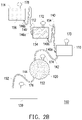
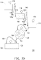
- FIGs. 2A to 2F are schematic views illustrating the detection method according to the flow passage apparatus 100 of FIG. 1 .
- FIG. 2A illustrates a schematic view illustrating the initial state of the flow passage apparatus 100 of FIG. 1 in which detection is about to begin.
- the three liquids 152, 154 and 156 are temporarily stored in the corresponding temporary tanks 110, 112 and 114 according to a sequence of the liquids being poured into the reaction tank 120 and a sequence in which the temporary tanks 110, 112 and 114 are disposed along the flowing direction of the liquids.
- the three liquids 152, 154 and 156 are the specimen 152, the cleaning liquid 154 and the reagent 156 respectively, and the specimen 152 is firstly poured into the reaction tank 120, followed by the cleaning liquid 154, and then followed by the reagent 156, the specimen 152 is temporarily stored in the first temporary tank 110, and the cleaning liquid 154 and the reagent 156 that are poured subsequently are respectively temporarily stored in the second temporary tank 112 and the third temporary tank 114 sequentially along an upstream direction from the first temporary tank 110.
- the temporary tanks for storing the liquids in the initial state, are connected to each other in sequence. In other words, in the initial state, there is no empty temporary tank between the temporary tanks for storing the liquids temporarily.
- FIG. 2A suggests, in the initial state, the first temporary tank 110, the second temporary tank 112 and the third temporary tank 114 temporarily storing the specimen 152, the cleaning liquid 154 and the reagent 156 respectively are connected to each other in sequence, and there is no empty temporary tank between the first temporary tank 110, the second temporary tank 112 and the third temporary tank 114.
- the liquids may be provided in the temporary tanks in advance, or collected from the outside and put into the temporary tanks. Alternatively, the liquids may also enter the temporary tanks through other storage tanks other than those of the flow passage apparatus of the embodiments of the invention.
- the microchannel disposed between the two adjacent temporary tanks of the temporary tanks has an inlet end and an outlet end, respectively connecting to the temporary tank located upstream and the temporary tank located downstream.
- the first microchannel 140 disposed between the temporary tank 110 and the second temporary tank 112 for example, the first microchannel 140 has an outlet end 140a and an inlet end 140b. The outlet end 140b is connected to the first temporary tank 110 located downstream, while the inlet end 140b is connected to the second temporary tank 112 located upstream.
- the fourth microchannel 146 disposed between the second temporary tank 112 and the third temporary tank 114 for example, the fourth microchannel 146 has an outlet end 146a and an inlet end 146b. The outlet end 146a is connected to the second temporary tank 112 located downstream, while the inlet end 146b is connected to the third temporary tank 114 located upstream.
- the inlet end and the outlet end of the microchannel disposed between the two adjacent temporary tanks of the temporary tanks are covered by the liquids in the temporary tanks that are connected to the inlet end and the outlet end.
- the outlet end 140a and the inlet end 140b of the first microchannel 140 disposed between the first temporary tank 110 and the second temporary tank 112 are covered by the specimen 152 in the first temporary tank 110 and the cleaning liquid 154 in the second temporary tank 112 respectively.
- the outlet end 146a and the inlet end 146b of the fourth microchannel 146 disposed between the second temporary tank 112 and the third temporary tank 114 are covered by the cleaning liquid 154 in the second temporary tank 112 and the reagent 156 in the third temporary tank 114 respectively.
- the liquid in each tank is driven to flow due to the capillary phenomenon and the siphon phenomenon.
- the liquid in the tank is driven into the microchannel due to the capillary phenomenon when the flow passage apparatus is kept standing. Then, an external force is applied to the liquid, so the liquid in the microchannel is driven to the next tank due to the siphon phenomenon.
- the flow passage apparatus illustrated in the embodiment of the invention may be rotated to apply a centrifugal force to the liquid as above mentioned external force, and the siphon phenomenon is induced in the liquid in the microchannel.
- a rotating axis X may be adopted as a center of rotation of the flow passage apparatus 100, and the flow passage apparatus 100 may be rotated along a rotating direction A to generate a centrifugal force to the liquid in the flow passage apparatus 100.
- the following is an example of applying the centrifugal force as the external force, detailing the process of the detection method of the flow passage apparatus 100 according to the embodiments of the invention.
- the specimen 152, the cleaning liquid 154 and the reagent 156 that are to be sequentially poured into the reaction tank 120 are temporarily stored in the first temporary tank 110, the second temporary tank 112 and the third temporary tank 114 respectively.
- the inlet end 140b, 146b and the outlet end 140a, 146a of the first microchannel 140 and the fourth microchannel 146 disposed between the first temporary tank 110, the second temporary tank 112 and the third temporary tank 114 are respectively covered by the specimen 152 in the first temporary tank 110, the cleaning liquid 154 in the second temporary tank 112 or the reagent 156 in the third temporary tank 114.
- the flow passage apparatus 100 is kept standing for a period. During the period, a portion of the specimen 152 temporarily stored in the first temporary tank 110 enters the second microchannel 142 due to the capillary phenomenon.
- the cleaning liquid 154 is unable to enter the first microchannel 140 by the capillary phenomenon.
- the inlet end 146b and the outlet end 146a of the fourth microchannel 146 are covered by the reagent 156 and the cleaning liquid 154 respectively, the reagent 156 is unable to enter the fourth microchannel 146 by the capillary phenomenon.
- the flow passage apparatus 100 is rotated to apply a centrifugal force to the liquid in the microchannel.
- the specimen 152 in the second microchannel 142 is subjected to the centrifugal force and the siphon phenomenon is induced to drive the specimen 152 in the first temporary tank 110 to enter the reaction tank 120.
- the cleaning liquid 154 in the second temporary tank 112 and the reagent 156 in the third temporary tank 114 are not driven when the flow passage apparatus 100 is rotated.
- the specimen 152 enters the reaction tank 120, while the cleaning liquid 154 and the reagent 156 remain stored temporarily in the second temporary tank 112 and the third temporary tank 114 respectively.
- the first temporary tank 110 is empty at this time, that is, the outlet end 140a of the first microchannel 140 is not covered. Consequently, when the flow passage apparatus 100 is kept standing for a period, a portion of the cleaning liquid 154 in the second temporary tank 112 enters the first microchannel 140 due to the capillary phenomenon. Meanwhile, a portion of the specimen 152 in the reaction tank 120 may also enter the third microchannel 144 due to the capillary phenomenon.
- the reagent 156 remains unable to enter the fourth microchannel 146 by the capillary phenomenon.
- the next rotation may serve to discharge the redundant waste liquid in the reaction tank 120 into the waste liquid tank 130.
- the flow passage apparatus 100 is rotated again to apply a centrifugal force to the liquid in the microchannel.
- the cleaning liquid 154 in the first microchannel 140 and the specimen 152 in the third microchannel 144 are subjected to the centrifugal force and the siphon phenomenon is induced to respectively drive the cleaning liquid 154 in the second temporary tank 112 into the first temporary tank 110 and drive the specimen 152 in the reaction tank 120 into the waste liquid tank 130.
- the reagent 156 in the third temporary tank 114 is not driven when the flow passage apparatus 100 is rotated.
- the specimen 152 enters the waste liquid tank 130
- the cleaning liquid 154 enters the first temporary tank 110
- the reagent 156 remains stored temporarily in the third temporary tank 114.
- the second temporary tank 112 is empty at this time, that is, the outlet end 146a of the fourth microchannel 146 is not covered. Consequently, when the flow passage apparatus 100 is kept standing for a period, a portion of the reagent 156 in the third temporary tank 114 may enter the fourth microchannel 146 due to the capillary phenomenon. Meanwhile, a portion of the cleaning liquid 154 in the first temporary tank 110 may also enter the second microchannel 142 due to the capillary phenomenon.
- the flow passage apparatus 110 is rotated again to apply a centrifugal force to the liquid in the microchannel.
- the cleaning liquid 154 in the second microchannel 142 and the reagent 156 in the fourth microchannel 146 are subjected to the centrifugal force and the siphon phenomenon is induced to respectively drive the cleaning liquid 154 in the first temporary tank 110 into the reaction tank 120 and drive the reagent 156 in the third temporary tank 114 into the second temporary tank 112.
- FIG. 2D suggests, after rotation of the flow passage apparatus 100, the cleaning liquid 154 enters the reaction tank 120, and the reagent 156 enters the second temporary tank 112. Specifically, after the cleaning liquid 154 enters the reaction tank 120, the first temporary tank 110 is empty at this time, that is, the outlet end 140a of the first microchannel 140 is not covered. Consequently, when the flow passage apparatus 100 is kept standing for a period, a portion of the reagent 156 in the second temporary tank 112 may enter the first microchannel 140 due to the capillary phenomenon. Meanwhile, a portion of the cleaning liquid 154 in the reaction tank 120 may also enter the third microchannel 144 due to the capillary phenomenon.
- next rotation may serve to discharge the redundant waste liquid in the reaction tank 120 into the waste liquid tank 130.
- the flow passage apparatus 100 is rotated again to apply a centrifugal force to the liquid in the microchannel.
- the cleaning liquid 154 in the third microchannel 144 and the reagent 156 in the first microchannel 140 are subjected to the centrifugal force and the siphon phenomenon is induced to respectively drive the cleaning liquid 154 in the reaction tank 120 into the waste liquid tank 130 and drive the reagent 156 in the second temporary tank 112 into the first temporary tank 110.
- FIG. 2E suggests, after rotation of the flow passage apparatus 100, the cleaning liquid 154 enters the waste liquid tank 130, and the reagent 156 enters the first temporary tank 110. Likewise, when the flow passage apparatus 100 is kept standing for a period, a portion of the reagent 156 in the first temporary tank 110 enters the second microchannel 142 due to the capillary phenomenon. Next, the flow passage apparatus 100 is rotated again to apply a centrifugal force to the liquid in the microchannel.
- the specimen 152, the cleaning liquid 154 and the reagent 156 may be poured into the reaction tank 120 in sequence, and before the pouring of the specimen 152, the cleaning liquid 154 and the reagent 156 into the reaction tank 120, the redundant waste liquid in the reaction tank 120 is discharged into the waste liquid tank 130.
- the inlet end and the outlet end of the microchannel disposed between the temporary tanks are covered by the liquids temporarily stored in the temporary tanks in the initial state to prevent the capillary phenomenon from being induced and consequently control the timing of the liquids pouring and leaving the reaction tank.
- the invention is able to admit samples stepwise and significantly reduce the usage of the microchannel, reducing the volume and simplifying manufacturing.
Landscapes
- Health & Medical Sciences (AREA)
- Chemical & Material Sciences (AREA)
- Life Sciences & Earth Sciences (AREA)
- Hematology (AREA)
- Engineering & Computer Science (AREA)
- Analytical Chemistry (AREA)
- General Health & Medical Sciences (AREA)
- Biomedical Technology (AREA)
- Physics & Mathematics (AREA)
- Dispersion Chemistry (AREA)
- Clinical Laboratory Science (AREA)
- Chemical Kinetics & Catalysis (AREA)
- Immunology (AREA)
- Biochemistry (AREA)
- General Physics & Mathematics (AREA)
- Urology & Nephrology (AREA)
- Pathology (AREA)
- Molecular Biology (AREA)
- Medicinal Chemistry (AREA)
- Food Science & Technology (AREA)
- Biophysics (AREA)
- Ecology (AREA)
- Biotechnology (AREA)
- Cell Biology (AREA)
- Microbiology (AREA)
- Automatic Analysis And Handling Materials Therefor (AREA)
- Investigating Or Analysing Biological Materials (AREA)
- Micromachines (AREA)
- Apparatus Associated With Microorganisms And Enzymes (AREA)
- Measuring Or Testing Involving Enzymes Or Micro-Organisms (AREA)
Claims (8)
- Nachweisverfahren zur Verwendung einer Durchflussvorrichtung (100) zum biologischen Mehrfachreaktionsnachweis, dadurch gekennzeichnet, dass es umfasst:in einem Anfangszustand, vorübergehendes Speichern einer ersten Flüssigkeit (152) in einem ersten temporären Tank (110) und vorübergehendes Speichern einer zweiten Flüssigkeit (154) in einem zweiten temporären Tank (112), wobei ein erster Mikrokanal (140) stromaufwärts des ersten temporären Tanks (110) angeordnet ist und ein Auslassende (140a) und ein Einlassende (140b) umfasst, die jeweils mit dem ersten temporären Tank (110) und dem zweiten temporären Tank (112) verbunden sind, im Ausgangszustand das Auslassende (140a) des ersten Mikrokanals (140) von der ersten Flüssigkeit (152) bedeckt ist, das Einlassende (140b) des ersten Mikrokanals (140) von der zweiten Flüssigkeit (154) bedeckt ist, und ein Teil der ersten Flüssigkeit (152) in einen zweiten Mikrokanal (142) eintritt, wobei der zweite Mikrokanal (142) stromabwärts des ersten temporären Tanks (110) angeordnet ist und mit dem ersten temporären Tank (110) verbunden ist; undnach dem Anfangszustand, Drehen der Durchflussvorrichtung (100) für ein erstes Mal, so dass die erste Flüssigkeit (152) den ersten temporären Tank (110) durch den zweiten Mikrokanal (142) durch eine Zentrifugalkraft und ein Siphonphänomen verlässt, während die zweite Flüssigkeit (154) in dem zweiten temporären Tank (112) verbleibt, wobei eine Vielzahl von Entlüftungen (170, 172) jeweils mit dem ersten temporären Tank (110) und dem zweiten temporären Tank (112) verbunden sind, so dass der erste temporäre Tank (110) und der zweite temporäre Tank (112) mit der Außenseite verbunden sind.
- Das Nachweisverfahren nach Anspruch 1, wobei im Anfangszustand die zweite Flüssigkeit (154) nicht in der Lage ist, durch ein Kapillarphänomen in den ersten Mikrokanal (140) einzutreten.
- Das Nachweisverfahren nach Anspruch 1 oder 2 umfasst ferner:Stehenlassen der Durchflussvorrichtung (100) für einen Zeitraum, so dass ein Teil der zweiten Flüssigkeit (154) in den ersten Mikrokanal (140) eintritt; undDrehen der Strömungsdurchlassvorrichtung (100) zu einem zweiten Zeitpunkt, so dass die zweite Flüssigkeit (154) den zweiten temporären Tank (112) durch den ersten Mikrokanal (140) verlässt und in den ersten temporären Tank (110) eintritt.
- Das Nachweisverfahren nach einem der Ansprüche 1 bis 3, umfassend:
Einfüllen der ersten Flüssigkeit (152) und der zweiten Flüssigkeit (154) in einen Reaktionsbehälter (120) zu unterschiedlichen Zeitpunkten. - Das Nachweisverfahren nach Anspruch 1, umfassend:
im Anfangszustand die erste Flüssigkeit (152) und die zweite Flüssigkeit (154) in dem ersten temporären Tank (110) bzw. dem zweiten temporären Tank (112) lagert und sich kein leerer temporärer Tank zwischen dem ersten temporären Tank (110) und dem zweiten temporären Tank (112) befindet. - Das Nachweisverfahren nach einem der Ansprüche 1 bis 4, wobei es sich bei der ersten Flüssigkeit (152) und der zweiten Flüssigkeit (154) jeweils um eine Probe, ein Reagenz oder eine Reinigungsflüssigkeit handelt.
- Das Nachweisverfahren nach Anspruch 1, umfassend:Einfüllen der ersten Flüssigkeit (152) und der zweiten Flüssigkeit (154) in einen Reaktionsbehälter (120) nacheinander zu verschiedenen Zeitpunkten,wobei der erste temporäre Tank (110) stromaufwärts des Reaktionstanks (120) und der zweite temporäre Tank (112) stromaufwärts des ersten temporären Tanks (110) angeordnet ist,wobei sich im Ausgangszustand kein leerer Zwischentank zwischen dem ersten Zwischentank (110) und dem zweiten Zwischentank (112) befindet.
- Das Nachweisverfahren nach Anspruch 7, wobei es sich bei der ersten Flüssigkeit (152) und der zweiten Flüssigkeit (154) jeweils um eine Probe, ein Reagenz oder eine Reinigungsflüssigkeit handelt.
Applications Claiming Priority (1)
| Application Number | Priority Date | Filing Date | Title |
|---|---|---|---|
| CN201710256394.0A CN108732339B (zh) | 2017-04-19 | 2017-04-19 | 用于多重反应生物检测的流道装置及其检测方法 |
Publications (2)
| Publication Number | Publication Date |
|---|---|
| EP3391966A1 EP3391966A1 (de) | 2018-10-24 |
| EP3391966B1 true EP3391966B1 (de) | 2022-05-04 |
Family
ID=59699473
Family Applications (1)
| Application Number | Title | Priority Date | Filing Date |
|---|---|---|---|
| EP17185295.7A Active EP3391966B1 (de) | 2017-04-19 | 2017-08-08 | Verfahren zur biologischen multireaktionsdetektion unter verwendung einer strömungskanalkonstruktion |
Country Status (4)
| Country | Link |
|---|---|
| US (1) | US11065617B2 (de) |
| EP (1) | EP3391966B1 (de) |
| JP (1) | JP2018174907A (de) |
| CN (1) | CN108732339B (de) |
Families Citing this family (4)
| Publication number | Priority date | Publication date | Assignee | Title |
|---|---|---|---|---|
| CN111122893B (zh) * | 2018-10-31 | 2024-04-12 | 天亮医疗器材股份有限公司 | 检测卡匣、检测方法及检测装置 |
| CN113970634B (zh) | 2020-07-22 | 2024-07-30 | 天亮医疗器材股份有限公司 | 生物检测系统及生物检测装置 |
| TWI777356B (zh) * | 2020-07-22 | 2022-09-11 | 天亮醫療器材股份有限公司 | 生物檢測系統及生物檢測裝置 |
| CN115074230B (zh) * | 2022-07-21 | 2023-05-23 | 北京泰豪生物科技有限公司 | 试剂控释模块、生物反应器以及生物检测装置 |
Family Cites Families (17)
| Publication number | Priority date | Publication date | Assignee | Title |
|---|---|---|---|---|
| US20010055812A1 (en) | 1995-12-05 | 2001-12-27 | Alec Mian | Devices and method for using centripetal acceleration to drive fluid movement in a microfluidics system with on-board informatics |
| US6632399B1 (en) * | 1998-05-22 | 2003-10-14 | Tecan Trading Ag | Devices and methods for using centripetal acceleration to drive fluid movement in a microfluidics system for performing biological fluid assays |
| GB9808836D0 (en) | 1998-04-27 | 1998-06-24 | Amersham Pharm Biotech Uk Ltd | Microfabricated apparatus for cell based assays |
| AU2002366474A1 (en) | 2001-12-14 | 2003-06-30 | Arkray, Inc. | Sample measuring device |
| JP2008525791A (ja) * | 2004-12-28 | 2008-07-17 | 松下電器産業株式会社 | 検査用デバイスおよび血液混合希釈方法 |
| CA2614180A1 (en) * | 2005-07-06 | 2007-01-11 | The Regents Of The University Of California | Apparatuses, systems, and methods for isolating and separating biological materials |
| EP2135069A4 (de) | 2007-03-02 | 2011-03-09 | Univ Laval | In reihe geschaltete heberventile für fluidik- oder mikrofluidik-vorrichtungen |
| SG10201608159XA (en) | 2012-02-29 | 2016-11-29 | Fluidigm Corp | Methods, systems, and devices for multiple single-cell capturing and processing using microfluidics |
| KR20150016043A (ko) * | 2013-08-02 | 2015-02-11 | 삼성전자주식회사 | 미세유동장치 및 그 제조방법 |
| CN103486091B (zh) * | 2013-09-25 | 2016-08-17 | 中国科学院长春光学精密机械与物理研究所 | 离心式微流控芯片的虹吸阀及其应用方法 |
| EP2952258A1 (de) * | 2014-06-06 | 2015-12-09 | Roche Diagnostics GmbH | Drehbare Kartusche zur Analyse einer biologischen Probe |
| CN107690582B (zh) | 2015-04-03 | 2023-10-20 | 雅培制药有限公司 | 用于样品分析的装置和方法 |
| US10775370B2 (en) | 2015-07-17 | 2020-09-15 | Stat-Diagnostica & Innovation, S.L. | Fluidic system for performing assays |
| CN205347420U (zh) * | 2015-12-07 | 2016-06-29 | 中国科学院苏州生物医学工程技术研究所 | 全自动核酸提取与pcr扩增微流控芯片 |
| CN105785054A (zh) * | 2016-05-13 | 2016-07-20 | 绍兴普施康生物科技有限公司 | 降钙素原定量检测的化学发光微流控盘片及其使用方法 |
| CN106268994B (zh) * | 2016-09-22 | 2018-04-20 | 博奥生物集团有限公司 | 一种离心式微流控芯片 |
| CN106525724A (zh) * | 2016-10-26 | 2017-03-22 | 杭州霆科生物科技有限公司 | 一种离心式全集成的甲醛和ph值的检测系统 |
-
2017
- 2017-04-19 CN CN201710256394.0A patent/CN108732339B/zh not_active Expired - Fee Related
- 2017-07-03 US US15/641,208 patent/US11065617B2/en active Active
- 2017-08-08 EP EP17185295.7A patent/EP3391966B1/de active Active
- 2017-08-10 JP JP2017155572A patent/JP2018174907A/ja active Pending
Also Published As
| Publication number | Publication date |
|---|---|
| US11065617B2 (en) | 2021-07-20 |
| CN108732339B (zh) | 2021-04-13 |
| CN108732339A (zh) | 2018-11-02 |
| EP3391966A1 (de) | 2018-10-24 |
| JP2018174907A (ja) | 2018-11-15 |
| US20180304256A1 (en) | 2018-10-25 |
Similar Documents
| Publication | Publication Date | Title |
|---|---|---|
| CN101520454B (zh) | 离心流体分析仪的转子 | |
| CN112756018B (zh) | 微流控芯片及体外检测系统 | |
| US7727472B2 (en) | Chemical analysis apparatus and chemical analysis cartridge | |
| US10031053B2 (en) | Microfluidic element for thoroughly mixing a liquid with a reagent | |
| EP2947463B1 (de) | Probenreinigungseinheit | |
| JP4775039B2 (ja) | マイクロ流体チップ | |
| KR101930610B1 (ko) | 생물학적 샘플을 분석하기 위한 회전가능한 카트리지 | |
| US20040203136A1 (en) | Microfluidics devices and methods of diluting samples and reagents | |
| KR102076809B1 (ko) | 시료 분석용 칩, 이를 포함하는 시료 분석용 디바이스, 그리고 시료 분석용 칩에 장착되는 카트리지 | |
| US11065617B2 (en) | Flow passage design for multi-reaction biological detection and detection method thereof | |
| KR20170029410A (ko) | 생물학적 샘플을 분석하기 위한 계측 챔버를 갖는 회전 가능한 카트리지 | |
| KR20190084046A (ko) | 마이크로 유체 장치 및 핵산 분석 방법 | |
| CN115518698B (zh) | 微流控芯片 | |
| US10166541B2 (en) | Centrifugal microfluidic platform for automated media exchange | |
| EP3235570B1 (de) | Biologische detektionskartusche und strömungsverfahren des erkannten fluids davon | |
| KR101965963B1 (ko) | 시료 분석용 칩, 이를 포함하는 시료 분석용 디바이스, 그리고 시료 분석용 칩에 장착되는 카트리지 | |
| US20060104863A1 (en) | Sample preparation system for a laboratory apparatus | |
| CN108554466B (zh) | 微流控芯片的离心分离装置 | |
| WO2003096008A1 (en) | Chemical analyzer and gene diagnosing apparatus | |
| TWI650542B (zh) | 用於多重反應生物檢測的流道設計及其檢測方法 | |
| CN118416971A (zh) | 一种微流控芯片及检测系统 | |
| CN113877646B (zh) | 一种微流控分配芯片 | |
| JP4593517B2 (ja) | 化学分析装置 | |
| CN119060840B (zh) | 一种高度集成式微流控芯片 | |
| CN109174788B (zh) | 微球清洗芯片及包含其的微球清洗装置 |
Legal Events
| Date | Code | Title | Description |
|---|---|---|---|
| PUAI | Public reference made under article 153(3) epc to a published international application that has entered the european phase |
Free format text: ORIGINAL CODE: 0009012 |
|
| STAA | Information on the status of an ep patent application or granted ep patent |
Free format text: STATUS: REQUEST FOR EXAMINATION WAS MADE |
|
| 17P | Request for examination filed |
Effective date: 20170808 |
|
| AK | Designated contracting states |
Kind code of ref document: A1 Designated state(s): AL AT BE BG CH CY CZ DE DK EE ES FI FR GB GR HR HU IE IS IT LI LT LU LV MC MK MT NL NO PL PT RO RS SE SI SK SM TR |
|
| AX | Request for extension of the european patent |
Extension state: BA ME |
|
| RBV | Designated contracting states (corrected) |
Designated state(s): AL AT BE BG CH CY CZ DE DK EE ES FI FR GB GR HR HU IE IS IT LI LT LU LV MC MK MT NL NO PL PT RO RS SE SI SK SM TR |
|
| STAA | Information on the status of an ep patent application or granted ep patent |
Free format text: STATUS: EXAMINATION IS IN PROGRESS |
|
| 17Q | First examination report despatched |
Effective date: 20190716 |
|
| GRAP | Despatch of communication of intention to grant a patent |
Free format text: ORIGINAL CODE: EPIDOSNIGR1 |
|
| STAA | Information on the status of an ep patent application or granted ep patent |
Free format text: STATUS: GRANT OF PATENT IS INTENDED |
|
| INTG | Intention to grant announced |
Effective date: 20220209 |
|
| GRAS | Grant fee paid |
Free format text: ORIGINAL CODE: EPIDOSNIGR3 |
|
| GRAA | (expected) grant |
Free format text: ORIGINAL CODE: 0009210 |
|
| STAA | Information on the status of an ep patent application or granted ep patent |
Free format text: STATUS: THE PATENT HAS BEEN GRANTED |
|
| AK | Designated contracting states |
Kind code of ref document: B1 Designated state(s): AL AT BE BG CH CY CZ DE DK EE ES FI FR GB GR HR HU IE IS IT LI LT LU LV MC MK MT NL NO PL PT RO RS SE SI SK SM TR |
|
| REG | Reference to a national code |
Ref country code: GB Ref legal event code: FG4D |
|
| REG | Reference to a national code |
Ref country code: CH Ref legal event code: EP |
|
| REG | Reference to a national code |
Ref country code: AT Ref legal event code: REF Ref document number: 1488438 Country of ref document: AT Kind code of ref document: T Effective date: 20220515 |
|
| REG | Reference to a national code |
Ref country code: IE Ref legal event code: FG4D Ref country code: DE Ref legal event code: R096 Ref document number: 602017056810 Country of ref document: DE |
|
| REG | Reference to a national code |
Ref country code: NL Ref legal event code: FP |
|
| REG | Reference to a national code |
Ref country code: LT Ref legal event code: MG9D |
|
| REG | Reference to a national code |
Ref country code: AT Ref legal event code: MK05 Ref document number: 1488438 Country of ref document: AT Kind code of ref document: T Effective date: 20220504 |
|
| PG25 | Lapsed in a contracting state [announced via postgrant information from national office to epo] |
Ref country code: SE Free format text: LAPSE BECAUSE OF FAILURE TO SUBMIT A TRANSLATION OF THE DESCRIPTION OR TO PAY THE FEE WITHIN THE PRESCRIBED TIME-LIMIT Effective date: 20220504 Ref country code: PT Free format text: LAPSE BECAUSE OF FAILURE TO SUBMIT A TRANSLATION OF THE DESCRIPTION OR TO PAY THE FEE WITHIN THE PRESCRIBED TIME-LIMIT Effective date: 20220905 Ref country code: NO Free format text: LAPSE BECAUSE OF FAILURE TO SUBMIT A TRANSLATION OF THE DESCRIPTION OR TO PAY THE FEE WITHIN THE PRESCRIBED TIME-LIMIT Effective date: 20220804 Ref country code: LT Free format text: LAPSE BECAUSE OF FAILURE TO SUBMIT A TRANSLATION OF THE DESCRIPTION OR TO PAY THE FEE WITHIN THE PRESCRIBED TIME-LIMIT Effective date: 20220504 Ref country code: HR Free format text: LAPSE BECAUSE OF FAILURE TO SUBMIT A TRANSLATION OF THE DESCRIPTION OR TO PAY THE FEE WITHIN THE PRESCRIBED TIME-LIMIT Effective date: 20220504 Ref country code: GR Free format text: LAPSE BECAUSE OF FAILURE TO SUBMIT A TRANSLATION OF THE DESCRIPTION OR TO PAY THE FEE WITHIN THE PRESCRIBED TIME-LIMIT Effective date: 20220805 Ref country code: FI Free format text: LAPSE BECAUSE OF FAILURE TO SUBMIT A TRANSLATION OF THE DESCRIPTION OR TO PAY THE FEE WITHIN THE PRESCRIBED TIME-LIMIT Effective date: 20220504 Ref country code: ES Free format text: LAPSE BECAUSE OF FAILURE TO SUBMIT A TRANSLATION OF THE DESCRIPTION OR TO PAY THE FEE WITHIN THE PRESCRIBED TIME-LIMIT Effective date: 20220504 Ref country code: BG Free format text: LAPSE BECAUSE OF FAILURE TO SUBMIT A TRANSLATION OF THE DESCRIPTION OR TO PAY THE FEE WITHIN THE PRESCRIBED TIME-LIMIT Effective date: 20220804 Ref country code: AT Free format text: LAPSE BECAUSE OF FAILURE TO SUBMIT A TRANSLATION OF THE DESCRIPTION OR TO PAY THE FEE WITHIN THE PRESCRIBED TIME-LIMIT Effective date: 20220504 |
|
| PG25 | Lapsed in a contracting state [announced via postgrant information from national office to epo] |
Ref country code: RS Free format text: LAPSE BECAUSE OF FAILURE TO SUBMIT A TRANSLATION OF THE DESCRIPTION OR TO PAY THE FEE WITHIN THE PRESCRIBED TIME-LIMIT Effective date: 20220504 Ref country code: PL Free format text: LAPSE BECAUSE OF FAILURE TO SUBMIT A TRANSLATION OF THE DESCRIPTION OR TO PAY THE FEE WITHIN THE PRESCRIBED TIME-LIMIT Effective date: 20220504 Ref country code: LV Free format text: LAPSE BECAUSE OF FAILURE TO SUBMIT A TRANSLATION OF THE DESCRIPTION OR TO PAY THE FEE WITHIN THE PRESCRIBED TIME-LIMIT Effective date: 20220504 Ref country code: IS Free format text: LAPSE BECAUSE OF FAILURE TO SUBMIT A TRANSLATION OF THE DESCRIPTION OR TO PAY THE FEE WITHIN THE PRESCRIBED TIME-LIMIT Effective date: 20220904 |
|
| PG25 | Lapsed in a contracting state [announced via postgrant information from national office to epo] |
Ref country code: SM Free format text: LAPSE BECAUSE OF FAILURE TO SUBMIT A TRANSLATION OF THE DESCRIPTION OR TO PAY THE FEE WITHIN THE PRESCRIBED TIME-LIMIT Effective date: 20220504 Ref country code: SK Free format text: LAPSE BECAUSE OF FAILURE TO SUBMIT A TRANSLATION OF THE DESCRIPTION OR TO PAY THE FEE WITHIN THE PRESCRIBED TIME-LIMIT Effective date: 20220504 Ref country code: RO Free format text: LAPSE BECAUSE OF FAILURE TO SUBMIT A TRANSLATION OF THE DESCRIPTION OR TO PAY THE FEE WITHIN THE PRESCRIBED TIME-LIMIT Effective date: 20220504 Ref country code: EE Free format text: LAPSE BECAUSE OF FAILURE TO SUBMIT A TRANSLATION OF THE DESCRIPTION OR TO PAY THE FEE WITHIN THE PRESCRIBED TIME-LIMIT Effective date: 20220504 Ref country code: DK Free format text: LAPSE BECAUSE OF FAILURE TO SUBMIT A TRANSLATION OF THE DESCRIPTION OR TO PAY THE FEE WITHIN THE PRESCRIBED TIME-LIMIT Effective date: 20220504 Ref country code: CZ Free format text: LAPSE BECAUSE OF FAILURE TO SUBMIT A TRANSLATION OF THE DESCRIPTION OR TO PAY THE FEE WITHIN THE PRESCRIBED TIME-LIMIT Effective date: 20220504 |
|
| REG | Reference to a national code |
Ref country code: DE Ref legal event code: R097 Ref document number: 602017056810 Country of ref document: DE |
|
| PLBE | No opposition filed within time limit |
Free format text: ORIGINAL CODE: 0009261 |
|
| STAA | Information on the status of an ep patent application or granted ep patent |
Free format text: STATUS: NO OPPOSITION FILED WITHIN TIME LIMIT |
|
| PG25 | Lapsed in a contracting state [announced via postgrant information from national office to epo] |
Ref country code: MC Free format text: LAPSE BECAUSE OF FAILURE TO SUBMIT A TRANSLATION OF THE DESCRIPTION OR TO PAY THE FEE WITHIN THE PRESCRIBED TIME-LIMIT Effective date: 20220504 Ref country code: AL Free format text: LAPSE BECAUSE OF FAILURE TO SUBMIT A TRANSLATION OF THE DESCRIPTION OR TO PAY THE FEE WITHIN THE PRESCRIBED TIME-LIMIT Effective date: 20220504 |
|
| 26N | No opposition filed |
Effective date: 20230207 |
|
| PG25 | Lapsed in a contracting state [announced via postgrant information from national office to epo] |
Ref country code: LU Free format text: LAPSE BECAUSE OF NON-PAYMENT OF DUE FEES Effective date: 20220808 |
|
| REG | Reference to a national code |
Ref country code: BE Ref legal event code: MM Effective date: 20220831 |
|
| PG25 | Lapsed in a contracting state [announced via postgrant information from national office to epo] |
Ref country code: SI Free format text: LAPSE BECAUSE OF FAILURE TO SUBMIT A TRANSLATION OF THE DESCRIPTION OR TO PAY THE FEE WITHIN THE PRESCRIBED TIME-LIMIT Effective date: 20220504 |
|
| PG25 | Lapsed in a contracting state [announced via postgrant information from national office to epo] |
Ref country code: IE Free format text: LAPSE BECAUSE OF NON-PAYMENT OF DUE FEES Effective date: 20220808 |
|
| PG25 | Lapsed in a contracting state [announced via postgrant information from national office to epo] |
Ref country code: BE Free format text: LAPSE BECAUSE OF NON-PAYMENT OF DUE FEES Effective date: 20220831 |
|
| PG25 | Lapsed in a contracting state [announced via postgrant information from national office to epo] |
Ref country code: HU Free format text: LAPSE BECAUSE OF FAILURE TO SUBMIT A TRANSLATION OF THE DESCRIPTION OR TO PAY THE FEE WITHIN THE PRESCRIBED TIME-LIMIT; INVALID AB INITIO Effective date: 20170808 |
|
| PG25 | Lapsed in a contracting state [announced via postgrant information from national office to epo] |
Ref country code: CY Free format text: LAPSE BECAUSE OF FAILURE TO SUBMIT A TRANSLATION OF THE DESCRIPTION OR TO PAY THE FEE WITHIN THE PRESCRIBED TIME-LIMIT Effective date: 20220504 |
|
| PG25 | Lapsed in a contracting state [announced via postgrant information from national office to epo] |
Ref country code: MK Free format text: LAPSE BECAUSE OF FAILURE TO SUBMIT A TRANSLATION OF THE DESCRIPTION OR TO PAY THE FEE WITHIN THE PRESCRIBED TIME-LIMIT Effective date: 20220504 |
|
| PG25 | Lapsed in a contracting state [announced via postgrant information from national office to epo] |
Ref country code: TR Free format text: LAPSE BECAUSE OF FAILURE TO SUBMIT A TRANSLATION OF THE DESCRIPTION OR TO PAY THE FEE WITHIN THE PRESCRIBED TIME-LIMIT Effective date: 20220504 |
|
| PG25 | Lapsed in a contracting state [announced via postgrant information from national office to epo] |
Ref country code: MT Free format text: LAPSE BECAUSE OF FAILURE TO SUBMIT A TRANSLATION OF THE DESCRIPTION OR TO PAY THE FEE WITHIN THE PRESCRIBED TIME-LIMIT Effective date: 20220504 |
|
| PG25 | Lapsed in a contracting state [announced via postgrant information from national office to epo] |
Ref country code: BG Free format text: LAPSE BECAUSE OF FAILURE TO SUBMIT A TRANSLATION OF THE DESCRIPTION OR TO PAY THE FEE WITHIN THE PRESCRIBED TIME-LIMIT Effective date: 20220504 |
|
| PG25 | Lapsed in a contracting state [announced via postgrant information from national office to epo] |
Ref country code: BG Free format text: LAPSE BECAUSE OF FAILURE TO SUBMIT A TRANSLATION OF THE DESCRIPTION OR TO PAY THE FEE WITHIN THE PRESCRIBED TIME-LIMIT Effective date: 20220504 |
|
| PGFP | Annual fee paid to national office [announced via postgrant information from national office to epo] |
Ref country code: GB Payment date: 20250612 Year of fee payment: 9 |
|
| PGFP | Annual fee paid to national office [announced via postgrant information from national office to epo] |
Ref country code: FR Payment date: 20250612 Year of fee payment: 9 |
|
| PGFP | Annual fee paid to national office [announced via postgrant information from national office to epo] |
Ref country code: NL Payment date: 20250825 Year of fee payment: 9 |
|
| PGFP | Annual fee paid to national office [announced via postgrant information from national office to epo] |
Ref country code: DE Payment date: 20250605 Year of fee payment: 9 |
|
| PGFP | Annual fee paid to national office [announced via postgrant information from national office to epo] |
Ref country code: IT Payment date: 20250821 Year of fee payment: 9 |
|
| PGFP | Annual fee paid to national office [announced via postgrant information from national office to epo] |
Ref country code: CH Payment date: 20250901 Year of fee payment: 9 |