EP3391481B1 - Pulse compression in chirped pulse laser systems - Google Patents
Pulse compression in chirped pulse laser systems Download PDFInfo
- Publication number
- EP3391481B1 EP3391481B1 EP16874208.8A EP16874208A EP3391481B1 EP 3391481 B1 EP3391481 B1 EP 3391481B1 EP 16874208 A EP16874208 A EP 16874208A EP 3391481 B1 EP3391481 B1 EP 3391481B1
- Authority
- EP
- European Patent Office
- Prior art keywords
- pulse
- optical
- dispersive
- compressor
- diffraction grating
- Prior art date
- Legal status (The legal status is an assumption and is not a legal conclusion. Google has not performed a legal analysis and makes no representation as to the accuracy of the status listed.)
- Active
Links
Images



Classifications
-
- H—ELECTRICITY
- H01—ELECTRIC ELEMENTS
- H01S—DEVICES USING THE PROCESS OF LIGHT AMPLIFICATION BY STIMULATED EMISSION OF RADIATION [LASER] TO AMPLIFY OR GENERATE LIGHT; DEVICES USING STIMULATED EMISSION OF ELECTROMAGNETIC RADIATION IN WAVE RANGES OTHER THAN OPTICAL
- H01S3/00—Lasers, i.e. devices using stimulated emission of electromagnetic radiation in the infrared, visible or ultraviolet wave range
- H01S3/005—Optical devices external to the laser cavity, specially adapted for lasers, e.g. for homogenisation of the beam or for manipulating laser pulses, e.g. pulse shaping
- H01S3/0057—Temporal shaping, e.g. pulse compression, frequency chirping
-
- H—ELECTRICITY
- H01—ELECTRIC ELEMENTS
- H01S—DEVICES USING THE PROCESS OF LIGHT AMPLIFICATION BY STIMULATED EMISSION OF RADIATION [LASER] TO AMPLIFY OR GENERATE LIGHT; DEVICES USING STIMULATED EMISSION OF ELECTROMAGNETIC RADIATION IN WAVE RANGES OTHER THAN OPTICAL
- H01S3/00—Lasers, i.e. devices using stimulated emission of electromagnetic radiation in the infrared, visible or ultraviolet wave range
- H01S3/02—Constructional details
- H01S3/025—Constructional details of solid state lasers, e.g. housings or mountings
- H01S3/027—Constructional details of solid state lasers, e.g. housings or mountings comprising a special atmosphere inside the housing
-
- H—ELECTRICITY
- H01—ELECTRIC ELEMENTS
- H01S—DEVICES USING THE PROCESS OF LIGHT AMPLIFICATION BY STIMULATED EMISSION OF RADIATION [LASER] TO AMPLIFY OR GENERATE LIGHT; DEVICES USING STIMULATED EMISSION OF ELECTROMAGNETIC RADIATION IN WAVE RANGES OTHER THAN OPTICAL
- H01S3/00—Lasers, i.e. devices using stimulated emission of electromagnetic radiation in the infrared, visible or ultraviolet wave range
- H01S3/10—Controlling the intensity, frequency, phase, polarisation or direction of the emitted radiation, e.g. switching, gating, modulating or demodulating
- H01S3/10007—Controlling the intensity, frequency, phase, polarisation or direction of the emitted radiation, e.g. switching, gating, modulating or demodulating in optical amplifiers
- H01S3/10023—Controlling the intensity, frequency, phase, polarisation or direction of the emitted radiation, e.g. switching, gating, modulating or demodulating in optical amplifiers by functional association of additional optical elements, e.g. filters, gratings, reflectors
- H01S3/1003—Controlling the intensity, frequency, phase, polarisation or direction of the emitted radiation, e.g. switching, gating, modulating or demodulating in optical amplifiers by functional association of additional optical elements, e.g. filters, gratings, reflectors tunable optical elements, e.g. acousto-optic filters, tunable gratings
-
- H—ELECTRICITY
- H01—ELECTRIC ELEMENTS
- H01S—DEVICES USING THE PROCESS OF LIGHT AMPLIFICATION BY STIMULATED EMISSION OF RADIATION [LASER] TO AMPLIFY OR GENERATE LIGHT; DEVICES USING STIMULATED EMISSION OF ELECTROMAGNETIC RADIATION IN WAVE RANGES OTHER THAN OPTICAL
- H01S3/00—Lasers, i.e. devices using stimulated emission of electromagnetic radiation in the infrared, visible or ultraviolet wave range
- H01S3/10—Controlling the intensity, frequency, phase, polarisation or direction of the emitted radiation, e.g. switching, gating, modulating or demodulating
- H01S3/10038—Amplitude control
-
- H—ELECTRICITY
- H01—ELECTRIC ELEMENTS
- H01S—DEVICES USING THE PROCESS OF LIGHT AMPLIFICATION BY STIMULATED EMISSION OF RADIATION [LASER] TO AMPLIFY OR GENERATE LIGHT; DEVICES USING STIMULATED EMISSION OF ELECTROMAGNETIC RADIATION IN WAVE RANGES OTHER THAN OPTICAL
- H01S3/00—Lasers, i.e. devices using stimulated emission of electromagnetic radiation in the infrared, visible or ultraviolet wave range
- H01S3/10—Controlling the intensity, frequency, phase, polarisation or direction of the emitted radiation, e.g. switching, gating, modulating or demodulating
- H01S3/10061—Polarization control
-
- H—ELECTRICITY
- H01—ELECTRIC ELEMENTS
- H01S—DEVICES USING THE PROCESS OF LIGHT AMPLIFICATION BY STIMULATED EMISSION OF RADIATION [LASER] TO AMPLIFY OR GENERATE LIGHT; DEVICES USING STIMULATED EMISSION OF ELECTROMAGNETIC RADIATION IN WAVE RANGES OTHER THAN OPTICAL
- H01S3/00—Lasers, i.e. devices using stimulated emission of electromagnetic radiation in the infrared, visible or ultraviolet wave range
- H01S3/005—Optical devices external to the laser cavity, specially adapted for lasers, e.g. for homogenisation of the beam or for manipulating laser pulses, e.g. pulse shaping
-
- H—ELECTRICITY
- H01—ELECTRIC ELEMENTS
- H01S—DEVICES USING THE PROCESS OF LIGHT AMPLIFICATION BY STIMULATED EMISSION OF RADIATION [LASER] TO AMPLIFY OR GENERATE LIGHT; DEVICES USING STIMULATED EMISSION OF ELECTROMAGNETIC RADIATION IN WAVE RANGES OTHER THAN OPTICAL
- H01S3/00—Lasers, i.e. devices using stimulated emission of electromagnetic radiation in the infrared, visible or ultraviolet wave range
- H01S3/005—Optical devices external to the laser cavity, specially adapted for lasers, e.g. for homogenisation of the beam or for manipulating laser pulses, e.g. pulse shaping
- H01S3/0078—Frequency filtering
-
- H—ELECTRICITY
- H01—ELECTRIC ELEMENTS
- H01S—DEVICES USING THE PROCESS OF LIGHT AMPLIFICATION BY STIMULATED EMISSION OF RADIATION [LASER] TO AMPLIFY OR GENERATE LIGHT; DEVICES USING STIMULATED EMISSION OF ELECTROMAGNETIC RADIATION IN WAVE RANGES OTHER THAN OPTICAL
- H01S3/00—Lasers, i.e. devices using stimulated emission of electromagnetic radiation in the infrared, visible or ultraviolet wave range
- H01S3/10—Controlling the intensity, frequency, phase, polarisation or direction of the emitted radiation, e.g. switching, gating, modulating or demodulating
- H01S3/10053—Phase control
-
- H—ELECTRICITY
- H01—ELECTRIC ELEMENTS
- H01S—DEVICES USING THE PROCESS OF LIGHT AMPLIFICATION BY STIMULATED EMISSION OF RADIATION [LASER] TO AMPLIFY OR GENERATE LIGHT; DEVICES USING STIMULATED EMISSION OF ELECTROMAGNETIC RADIATION IN WAVE RANGES OTHER THAN OPTICAL
- H01S3/00—Lasers, i.e. devices using stimulated emission of electromagnetic radiation in the infrared, visible or ultraviolet wave range
- H01S3/14—Lasers, i.e. devices using stimulated emission of electromagnetic radiation in the infrared, visible or ultraviolet wave range characterised by the material used as the active medium
- H01S3/16—Solid materials
- H01S3/1601—Solid materials characterised by an active (lasing) ion
- H01S3/162—Solid materials characterised by an active (lasing) ion transition metal
- H01S3/1625—Solid materials characterised by an active (lasing) ion transition metal titanium
-
- H—ELECTRICITY
- H01—ELECTRIC ELEMENTS
- H01S—DEVICES USING THE PROCESS OF LIGHT AMPLIFICATION BY STIMULATED EMISSION OF RADIATION [LASER] TO AMPLIFY OR GENERATE LIGHT; DEVICES USING STIMULATED EMISSION OF ELECTROMAGNETIC RADIATION IN WAVE RANGES OTHER THAN OPTICAL
- H01S3/00—Lasers, i.e. devices using stimulated emission of electromagnetic radiation in the infrared, visible or ultraviolet wave range
- H01S3/14—Lasers, i.e. devices using stimulated emission of electromagnetic radiation in the infrared, visible or ultraviolet wave range characterised by the material used as the active medium
- H01S3/16—Solid materials
- H01S3/163—Solid materials characterised by a crystal matrix
- H01S3/1631—Solid materials characterised by a crystal matrix aluminate
- H01S3/1636—Al2O3 (Sapphire)
-
- H—ELECTRICITY
- H01—ELECTRIC ELEMENTS
- H01S—DEVICES USING THE PROCESS OF LIGHT AMPLIFICATION BY STIMULATED EMISSION OF RADIATION [LASER] TO AMPLIFY OR GENERATE LIGHT; DEVICES USING STIMULATED EMISSION OF ELECTROMAGNETIC RADIATION IN WAVE RANGES OTHER THAN OPTICAL
- H01S3/00—Lasers, i.e. devices using stimulated emission of electromagnetic radiation in the infrared, visible or ultraviolet wave range
- H01S3/23—Arrangements of two or more lasers not provided for in groups H01S3/02 - H01S3/22, e.g. tandem arrangements of separate active media
- H01S3/2308—Amplifier arrangements, e.g. MOPA
Definitions
- the following description relates to optical pulse compression in chirped pulse laser systems.
- Chirped pulse laser systems such as chirped pulse amplifiers (CPA), amplify short duration laser pulses by stretching a short duration optical pulse, amplifying the stretched optical pulse, and compressing the amplified optical pulse.
- CPAs chirped pulse amplifiers
- Optical pulse compression in CPAs is typically performed by diffraction gratings, and the surfaces of these diffraction gratings may deteriorate due to the high field intensity of the compressed amplified optical pulse incident upon the diffraction gratings.
- US20140166906 A1 describes an extreme ultra violet (EUV) generation device including a light source for outputting a laser beam, a pulse width compression system for compressing a pulse width of the laser beam, a gas cell for receiving the laser beam having the compressed pulse width incident from the pulse width compression system and generating EUV light, and a vacuum chamber housing the pulse width compression system and the gas cell.
- EUV extreme ultra violet
- a chirped pulse laser system (such as a chirped pulse amplifier (CPA)) includes a programmable optical dispersive filter (PODF) and a pulse compressor, among other components.
- the pulse compressor includes optical elements in a vacuum chamber (e.g., a chamber that operates at less than 10 -3 Torr, less than 2 ⁇ 10 -8 Torr, or another high vacuum pressure), and the optical elements define an optical path through the pulse compressor.
- the pulse compressor may be operated such that an optical signal in the optical path of the pulse compressor is below a critical power at which self-channeling effects may appear.
- the optical elements of the pulse compressor are arranged to compress the optical pulse, and include diffraction gratings and a dispersive mirror.
- each diffraction grating has a ridged reflective surface and the dispersive mirror has a smooth reflective surface. Because the ridged nanostructure of the diffraction gratings makes them susceptible to field enhancement, the dispersive mirror's flat reflective surface may have a higher damage threshold relative to the diffraction gratings.
- the smooth reflective surface of the dispersive mirror can be formed by alternating layers of dielectric materials on a substrate (e.g., alternating layers of high- and low-index materials, such as Titanium dioxide (TiO 2 ) and Silicon dioxide (SiO 2 ), respectively). In some instances, the dispersive mirror is the last optical element in the optical path.
- the dispersive mirror provides for second order dispersion (or group delay dispersion) of approximately (+/-)300 femtoseconds squared (fs 2 ) for optical pulses with a duration of approximately 15-17 femtoseconds (fs).
- a dispersive mirror may better withstand high-intensity optical pulses found in a chirped pulse laser system compared to diffraction gratings (e.g., a dispersive mirror may have a damage threshold more than four (4) times greater than the damage threshold of a diffraction grating).
- the dispersive mirror may be used in a pulse compressor of a CPA to reduce the intensity and the damage threshold fluence incident upon one or more diffraction gratings (e.g., the last diffraction grating in an optical path in the pulse compressor) in the pulse compressor by an order of magnitude or more (e.g., by approximately forty percent (40%)).
- a wave plate may be used to modify the polarization of the optical pulse in a pulse compressor, which may reduce the damage threshold of the dispersive mirror in the pulse compressor.
- a pulse compressor comprising a dispersive mirror may produce optical pulses having higher peak power, and may do so over the same or similar lifetime as previous systems with only diffraction gratings.
- a pulse compressor comprising a dispersive mirror may produce optical pulses having the same or similar peak power as previous systems with only diffraction gratings, but with smaller optical elements and therefore reduced costs (e.g., through reduced costs related to one or more of the diffraction gratings or other optical elements in the pulse compressor).
- the dispersive mirror and diffraction gratings of a pulse compressor may operate under high vacuum pressures (e.g., less than 10 -3 Torr), reducing cumulative non-linear effects caused by certain types of media or combinations of media (e.g., air, Helium, glass, or combinations thereof).
- the pulse compressor may be configured to produce a transform-limited optical pulse with a negligible B-Integral.
- the pulse compressor may be configured to produce a single-cycle optical pulse.
- FIG. 1 is a block diagram showing aspects of an example pulse amplification system 100.
- the pulse amplification system 100 includes a pulse generator 102, a pulse stretcher 104, a pulse amplifier 106, and a pulse compressor 108.
- a pulse amplification system may include additional or different components.
- the pulse amplification system 100 amplifies broad-spectrum, short duration chirped optical pulses, such as, for example, optical pulses with a duration of less than 50 fs.
- the duration of the pulse may be measured as the full width of the pulse at half maximum intensity (FWHM).
- the pulse amplification system 100 may be configured to produce a pulse with a duration of approximately 15-17 fs with a peak power of approximately 100 TeraWatts (TW).
- TW TeraWatts
- the example pulse generator 102 generates an optical pulse 103 for amplification by the pulse amplification system 100.
- the optical pulse 103 is a Fourier transform limited (or transform-limited) optical pulse.
- the pulse generator 102 includes a femtosecond laser oscillator, such as, for example, a femtosecond Ti:sapphire laser.
- the pulse generator 102 may include additional or different components.
- the pulse generator 102 includes a chirped pulse amplifier (CPA) in addition to a femtosecond laser oscillator.
- CPA chirped pulse amplifier
- the example pulse stretcher 104 receives the optical pulse 103 generated by the pulse generator 102, and stretches the optical pulse 103 to produce the stretched optical pulse 105.
- the stretched optical pulse 105 may be a chirped optical pulse, with a frequency that is time dependent. The frequency of the stretched optical pulse 105 may increase with time (an up-chirped pulse) or decrease with time (a down-chirped pulse).
- the pulse stretcher 104 stretches the optical pulse 103 using one or more dispersive optical elements, such as diffraction gratings, optical glass with chromatic dispersion characteristics (e.g., SCHOTT SF57 glass).
- the dispersive optical elements of the pulse stretcher 104 cause the different wavelength components of the optical pulse 103 to disperse spatially and temporally from one another while travelling through the pulse stretcher 104, causing the stretched optical pulse 105 to have a lower intensity (e.g., an intensity below the damage threshold of the pulse amplifier 106).
- the dispersive optical elements of the pulse stretcher 104 may positively or negatively disperse the chirped optical pulse received from the pulse generator 102.
- the spectral phase of the optical signal produced by the pulse stretcher 104 can be modified.
- the pulse amplification system 100 may include a programmable optical dispersive filter (PODF) that modifies the spectral phase of the optical signal provided to the pulse amplifier 106.
- PODF programmable optical dispersive filter
- An optical signal may have another form, for example, with the spectral intensity and spectral phase having another representation.
- a PODF is used to modify the spectral phase of an optical signal such that the optical signal output from the pulse compressor 108 has a flat spectral phase (with all frequency components having the same phase), or to modify the spectral phase of an optical signal such that the optical signal output from the pulse compressor 108 has another spectral phase profile.
- the example pulse stretcher 104 includes or is coupled to an acousto-optic programmable dispersive filter (AOPDF), which modifies the spectral phase of the stretched optical pulse 105 while travelling through the AOPDF.
- the spectral phase modification may be based on an acoustic signal received by the AOPDF.
- the AOPDF may include a piezoelectric medium having mechanical properties (e.g., mechanical stress) that are controlled by an applied acoustic signal and influence a spectral phase modification applied to the optical signal.
- the AOPDF may modify the spectral phase of the stretched optical pulse 105 such that the pulse compressor 108 produces an optical signal that has a flat spectral phase over the different wavelength components of the optical signal.
- the AOPDF may be programmed based on properties of the pulse compressor 108.
- the AOPDF may be programmed to modify the spectral phase of the optical signal based on the optical properties of dispersive optical elements in the pulse compressor 108.
- the example pulse amplifier 106 receives the stretched optical pulse 105 from the pulse stretcher 104, and increases the peak power of the stretched optical pulse.
- the example pulse amplifier 106 increases the power of the stretched optical pulse using one or more optical elements having a gain medium (e.g., Ti:sapphire) which transfers energy input to the gain medium (e.g., electrical energy) to the stretched optical pulse 105 to produce the amplified optical pulse 107.
- the pulse amplifier 106 includes a multipass amplifier.
- the example pulse compressor 108 is a system of one or more components that receives the amplified optical pulse 107 from the pulse amplifier 106, and compresses the amplified optical pulse 107 using optical dispersion.
- the example pulse compressor 108 compresses the pulse using one or more dispersive optical elements, such as, for example, diffraction gratings or dispersive mirrors.
- the dispersive optical elements of the pulse compressor 108 cause an opposite magnitude dispersion of the optical pulse than the dispersive optical elements of the pulse stretcher 104. For example, where the pulse stretcher 104 positively disperses the optical pulse, the pulse compressor 108 negatively disperses the optical pulse.
- the pulse compressor 108 is configured to at least approximately cancel out the amount of dispersion imparted to the chirped optical pulse 103 by the pulse stretcher 104.
- the pulse compressor 108 includes a highly dispersive mirror (HDM) that has a smooth reflective surface and is composed of layers of dielectric materials.
- the HDM includes alternating layers of high- and low-index dielectric materials, such as Titanium dioxide (TiO 2 ) and Silicon dioxide (SiO 2 ), respectively.
- the total physical thickness of the high-index material is approximately 4700 nm, while the total physical thickness of the low-index material is approximately 7700 m. Other materials and layer thickness can be used.
- FIG. 2 is a diagram showing aspects of an example chirped pulse amplifier (CPA) system 200.
- the CPA system 200 includes a pulse generator 202, a pulse stretcher 204, a programmable optical dispersive filter (PODF) 206, a pulse amplifier 208, and a pulse compressor 210.
- the example CPA system 200 amplifies broad-spectrum, short duration chirped optical pulses, such as, for example, those with durations of less than 50 fs.
- the CPA system 200 may be configured to produce an amplified optical pulse having a duration of approximately 15-17 fs, a spectrum of 730-870 nm, and peak power of approximately 100 TW.
- the CPA system 200 may be configured to generate single-cycle optical pulses.
- the CPA system 200 may be configured to produce an amplified optical pulse having a duration of approximately 2.66 fs at a wavelength of approximately 800 nm.
- the pulse generator 202 generates an optical pulse that is transmitted to the pulse stretcher 204.
- the example pulse generator 202 includes one or more components that generate a broad-spectrum ultrashort optical pulse.
- the pulse generator 202 can produce Fourier transform limited ultrashort optical pulses.
- the pulse generator 202 may generate an optical pulse having a duration of 15-17 fs and spectrum of 730-870 nm.
- the example pulse generator 202 is implemented similar to the pulse generator 102 of FIG. 1 .
- the pulse generator 202 may include a femtosecond laser oscillator, such as a femtosecond Ti:sapphire laser.
- the example pulse stretcher 204 includes one or more dispersive optical elements that stretch an optical signal as it traverses an optical path through the pulse stretcher 204.
- the dispersive optical elements of the example pulse stretcher 204 temporally broaden the pulse by spatially dispersing the different wavelength components of the optical pulse received from the pulse generator 202.
- the dispersive optical elements may positively or negatively disperse the optical pulse.
- the pulse stretcher 204 is implemented similar to the pulse stretcher 104 of FIG. 1 .
- the pulse stretcher 204 may include one or more diffraction gratings that act to disperse the optical pulse from the pulse generator 202.
- the pulse stretcher 204 receives the optical pulse from the pulse generator 202, stretches the optical pulse, and transmits the stretched optical pulse to the PODF 206.
- the example PODF 206 includes one or more components that modify the spectral phase of the optical pulse as it travels through the PODF 206.
- the PODF 206 includes an acousto-optic programmable dispersive filter (AOPDF), which receives an acoustic signal and modifies the spectral phase of an optical pulse travelling through the PODF based on the acoustic signal.
- AOPDF acousto-optic programmable dispersive filter
- the PODF 206 is implemented using a DAZZLER system available from FASTLITE. Another type of PODF may be used, and the PODF 206 may include additional or different components.
- the PODF 206 receives the stretched optical pulse from the pulse stretcher 204, modifies the spectral phase of the stretched optical pulse, and transmits the phase-modified optical pulse to the pulse amplifier 208.
- the example pulse amplifier 208 includes one or more components that increase the power of an optical pulse using one or more optical elements having a gain medium (e.g., Ti:sapphire), which transfers energy input to the gain medium (e.g., electrical energy) to the optical pulse.
- the pulse amplifier 208 includes a multipass amplifier. In the example shown, the pulse amplifier 208 receives the phase-modified optical pulse from the PODF 206, amplifies the optical pulse, and transmits the amplified optical pulse to the pulse compressor 210.
- the example pulse compressor 210 includes one or more dispersive optical elements that compress an optical signal as it traverses an optical path through the pulse compressor 210.
- the dispersive optical elements of the example pulse compressor 210 temporally compress the pulse by spatially dispersing the different wavelength components of the optical pulse received from the pulse amplifier 208.
- the dispersive optical elements of the pulse compressor 210 are in a vacuum chamber.
- the example pulse compressor 210 includes an optical inlet 211, a first diffraction grating 212, a second diffraction grating 213, a third diffraction grating 214 a fourth diffraction grating 215, a wave plate 216, a dispersive mirror 217, and an optical outlet 218.
- the pulse compressor 210 includes additional optical elements, such as, for example, one or more mirrors or thin optics between the fourth diffraction grating 215 and the dispersive mirror 217.
- the pulse compressor 210 receives the amplified optical pulse from the pulse amplifier 208 at the optical inlet 211, compresses the amplified optical pulse, and transmits the compressed optical pulse to the chamber 230 from the optical outlet 218.
- the optical pulse produced from the optical outlet 218 is a transform-limited pulse.
- the pulse compressor 210 produces a transform-limited pulse with a negligible B-Integral.
- the beam diameter of the optical pulse at the outlet 218 is approximately 150 millimeters (mm); or the pulse compressor 210 may produce an optical signal having another beam diameter.
- the optical inlet 211 comprises glass, while the optical outlet 218 comprises an optical tunnel to the chamber 230.
- the optical tunnel of the optical outlet 218 may be operated at a vacuum pressure, such as, for example, the vacuum pressure of the pulse compressor (e.g., less than 10 -3 Torr).
- the example chamber 230 includes components that interact with the compressed optical pulse from the optical outlet 218.
- the chamber 230 comprises a vacuum chamber operated at a vacuum pressure (e.g., less than 10 -3 Torr).
- the vacuum chamber of the chamber 230 is operated at the same vacuum pressure as the vacuum chamber of the pulse compressor 210.
- the chamber 230 includes crystalline materials or other elements that can be used to produce high-energy particles based on the optical pulse from the pulse compressor 210.
- the chamber 230 may produce a particle beam, a gamma ray beam, an x-ray beam or another type of output.
- the chamber 230 may be configured to produce a x-ray beam by Betatron, Compton, or K-alpha scattering.
- the chamber 120 may be configured to produce high duty cycle particle beams or radiation beams.
- the diffraction gratings 212-215, wave plate 216, and the dispersive mirror 217 define an optical path within the pulse compressor 210 that includes path portions 221-227.
- the optical path generally extends from the optical inlet 211 to the optical outlet 218 and includes the series of optical elements and path portions between respective pairs of the optical elements.
- the path portions 221-227 are regions of the vacuum chamber that reside between the optical elements in the pulse compressor 210, and during operation of the pulse compressor 210, the path portions 221-227 contain gas (e.g., air, Helium, or another gas) at vacuum pressure (e.g., in the range of 2 ⁇ 10 -8 to 3 ⁇ 10 -8 Torr).
- the example diffraction gratings 212-215 and the dispersive mirror 217 are arranged in the pulse compressor 210 such that they disperse the optical pulse in the optical path.
- the diffraction gratings 212-215 and the dispersive mirror 217 may impart positive or negative dispersion on the optical pulse, depending on the dispersion imparted by the pulse stretcher 204 in the example CPA system 200.
- the pulse compressor 210 negatively disperses the optical pulse.
- the pulse compressor 210 is configured to at least approximately cancel out the amount of dispersion imparted to the optical pulse by the pulse stretcher 204.
- the diffraction gratings 212-215 are arranged before the dispersive mirror 217 in the optical path.
- the diffraction gratings 212-215 may each have 1480 lines per millimeter (l/mm), and may be displaced from one another by 1 mm. Where the diffraction gratings 212-215 are displaced from one another by 1 mm, the diffraction gratings 212-215 may each induce a dispersion of 5500 fs 2 and 11,000 fs 3 onto an optical pulse in the optical path.
- the example wave plate 216 modifies a polarization of the optical pulse as it travels therethrough.
- the wave plate 216 may modify the polarization of the optical pulse such that it is entirely s-polarized (e.g., by converting p-polarized components to s-polarized components of the optical pulse), which may impart less damage when incident upon the dispersive mirror 217.
- the wave plate 216 may modify the polarization of the optical pulse in another manner, such as, for example, modifying the optical pulse to be circularly polarized.
- the wave plate 216 is a half-wave plate. In some implementations, the wave plate 216 is a quarter-wave plate.
- the wave plate 216 is a segmented wave plate (e.g., with a mosaic pattern) that creates radial-typed polarizations.
- the wave plate 216 is between the last diffraction grating 215 (the final diffraction grating in the optical path) and the dispersive mirror 217.
- the pulse compressor 210 may include no wave plates or may include additional wave plates.
- the example diffraction gratings 212-215, wave plate 216, and dispersive mirror 217 of the pulse compressor 210 reside in a vacuum chamber.
- one or more diffraction gratings e.g., the diffraction gratings 212, 213 may reside outside of the vacuum chamber.
- the vacuum chamber may be configured to operate at a vacuum pressure of less than 10 -3 Torr.
- the diffraction gratings 212-215, wave plate 216, and dispersive mirror 217 reside in a vacuum chamber that operates at approximately 2.5 ⁇ 10 -8 Torr (in the range of 2 ⁇ 10 -8 to 3 ⁇ 10 -8 Torr).
- the vacuum chamber may be configured to operate at a vacuum pressure that is based on the peak power of the optical pulses travelling in the pulse compressor 210.
- the vacuum chamber of the pulse compressor 210 may be operated at a particular vacuum pressure such that the peak power of the optical pulses is below a critical power, and the optical pulses may avoid self-channeling effects while traversing the optical path through the pulse compressor 210.
- the optical pulses produced by the pulse compressor 210 may have higher peak power.
- the dispersive mirror 217 imparts a second order dispersion (or group delay dispersion) of approximately (+/-)300 fs 2 onto an optical pulse with a spectrum centered around 800 nm (e.g., having a spectrum of 730-870 nm).
- the second order dispersion characteristics of the dispersive mirror 217 are wavelength dependent.
- Trace 304 is an example measurement of temporal intensity incident upon a last diffraction grating in a pulse compressor of a pulse amplification system, such as a CPA, that includes a dispersive mirror as the last optical element in the optical path of the pulse compressor.
- the measurements of trace 304 may be indicative of the intensity incident upon diffraction grating 215 of FIG. 2 relative to a system similar to what is shown in FIG. 2 except that it does not include the dispersive mirror 217.
- the inclusion of a dispersive mirror 217 as the last optical element in the optical path of the pulse compressor 210 may reduce the intensity of the optical pulse incident upon the diffraction grating 215, which may allow for a longer lifespan and increased duty cycle of the diffraction grating.
- FIG. 4 is a flow diagram showing an example process 400 for amplifying chirped optical pulses.
- the process 400 may be implemented using the pulse amplification system 100 of FIG. 1 , the CPA system 200 of FIG. 2 or another system.
- one or more operations of the process 400 are performed by optical elements or other components operating under high vacuum pressure.
- the diffraction gratings and dispersive mirror that compress the optical pulse at 450 may reside in a vacuum chamber that operates at pressures below 10 -3 Torr.
- a chirped optical pulse is generated using a femtosecond oscillator, such as a femtosecond Ti:sapphire laser.
- the optical pulse is stretched using one or more diffraction gratings.
- the diffraction gratings may impart either positive or negative dispersion upon the optical pulse.
- the spectral phase of the stretched optical pulse is modified using a programmable optical dispersive filter (PODF).
- PODF may be implemented using an AOPDF, which modifies the spectral phase of the optical pulse based on a received acoustic signal.
- the optical pulse is amplified using a multipass amplifier.
- a chirped pulse laser system includes a pulse compressor with a dispersive mirror.
- a chirped pulse laser system includes a programmable optical dispersive filter (PODF) and a pulse compressor that receives an optical pulse based on an output of the PODF.
- the PODF is operable to modify a spectral phase of optical pulses.
- the pulse compressor includes optical elements in a vacuum chamber. The optical elements define an optical path through the pulse compressor, and are arranged to disperse the optical pulse in the optical path.
- the optical elements include diffraction gratings and a dispersive mirror.
- the dispersive mirror has a smooth reflective surface that defines a portion of the optical path.
- the dispersive mirror may include one or more dielectric materials on a substrate.
- the dispersive mirror may include alternating layers of a high-index dielectric material and a low-index dielectric material.
- the high-index material may include Titanium dioxide (TiO 2 ) and the low-index material may include Silicon dioxide (SiO 2 ).
- the total thickness of the layers of Titanium dioxide (TiO 2 ) may be approximately 4700 nm, and the total thickness of the layers of Silicon dioxide (SiOz) may be approximately 7700 nm.
- the dispersive mirror may be operable to impart a second order dispersion of approximately (+/-)300 fs 2 to the optical pulse.
- the vacuum chamber may be configured to operate at pressures less than 10 -3 Torr.
- the PODF may include an acousto-optic programmable dispersive filter (AOPDF), which may be operable to modify the spectral phase of an optical signal based on an acoustic signal received by the PODF.
- the optical elements of the pulse compressor may include a wave plate operable to modify a polarization of the optical pulse. The wave plate may reside in the optical path between the dispersive mirror and the last diffraction grating. The diffraction gratings may be arranged before the dispersive mirror in the optical path.
- Implementations of the first example may include one or more of the following features.
- the system may include a pulse generator, a pulse stretcher that receives an output of the pulse generator, and a pulse amplifier that receives an output of the PODF.
- the pulse stretcher may include one or more optical elements that disperse optical pulses, and the pulse amplifier may be operable to increase a power of optical pulses.
- the pulse compressor may be arranged to receive an output of the pulse amplifier.
- the pulse generator may include a femtosecond laser oscillator.
- the optical elements may define an optical path between an optical inlet of the pulse compressor and an optical outlet of the pulse compressor.
- the pulse compressor may include a first diffraction grating arranged to receive the optical pulse from the optical inlet, a second diffraction grating arranged to receive the optical pulse from the first diffraction grating, a third diffraction grating arranged to receive the optical pulse from the second diffraction grating, and a fourth diffraction grating arranged to receive the optical pulse from the third diffraction grating.
- the dispersive mirror may be arranged to provide the optical pulse to the optical outlet.
- compressing a chirped optical pulse includes modifying a spectral phase of an optical pulse by operation of a programmable optical dispersive filter (PODF) and compressing the optical pulse by operation of a pulse compressor.
- the pulse compressor includes optical elements in a vacuum chamber.
- the optical elements define an optical path in the pulse compressor, and are arranged to disperse the optical pulse in the optical path.
- the optical elements include diffraction gratings and a dispersive mirror.
- the dispersive mirror has a smooth reflective surface that defines a portion of the optical path.
- the dispersive mirror may include one or more dielectric materials on a substrate.
- the dispersive mirror may include alternating layers of a high-index dielectric material and a low-index dielectric material.
- the high-index material may include Titanium dioxide (TiO 2 ) and the low-index material may include Silicon dioxide (SiO 2 ).
- the total thickness of the layers of Titanium dioxide (TiO 2 ) may be approximately 4700 nm, and the total thickness of the layers of Silicon dioxide (SiO 2 ) may be approximately 7700 nm.
- the dispersive mirror may be operable to impart a second order dispersion of approximately (+/-)300 fs 2 to the optical pulse.
- the vacuum chamber may be operated at pressures less than 10 -3 Torr.
- Implementations of the second example may include one or more of the following features.
- the method may include amplifying the optical pulse by operation of a pulse amplifier before compressing the optical pulse.
- the method may include generating the optical pulse using a femtosecond laser oscillator.
- the method may include stretching the optical pulse by operation of a pulse stretcher before modifying the spectral phase of the optical pulse.
- the pulse stretcher may include dispersive optical elements.
- the PODF may include an acousto-optic programmable dispersive filter (AOPDF), and the method may include modifying the spectral phase of the optical pulse base on an acoustic signal received by the AOPDF.
- AOPDF acousto-optic programmable dispersive filter
- Implementations of the second example may include one or more of the following features.
- Compressing the optical pulse may include compressing the optical pulse by operation of the diffraction gratings before compressing the optical pulse by operation of the dispersive mirror.
- Compressing the optical pulse may include modifying a polarization of the optical pulse using a wave plate.
- Compressing the optical pulse may include imparting a second order dispersion of approximately (+/-)300 fs 2 to the optical pulse by operation of the dispersive mirror.
- the compressed optical pulse may have a peak power of greater than 10 GigaWatts (GW).
- the optical elements may define an optical path between an optical inlet of the pulse compressor and an optical outlet of the pulse compressor.
- the pulse compressor may include a first diffraction grating arranged to receive the optical pulse from the optical inlet, a second diffraction grating arranged to receive the optical pulse from the first diffraction grating, a third diffraction grating arranged to receive the optical pulse from the second diffraction grating, and a fourth diffraction grating arranged to receive the optical pulse from the third diffraction grating.
- the dispersive mirror may be arranged to provide the optical pulse to the optical outlet.
Landscapes
- Physics & Mathematics (AREA)
- Electromagnetism (AREA)
- Engineering & Computer Science (AREA)
- Plasma & Fusion (AREA)
- Optics & Photonics (AREA)
- Lasers (AREA)
Description
- This application claims priority to
U.S. Provisional Application No.62/269,183, filed December 18, 2015 - The following description relates to optical pulse compression in chirped pulse laser systems.
- Chirped pulse laser systems, such as chirped pulse amplifiers (CPA), amplify short duration laser pulses by stretching a short duration optical pulse, amplifying the stretched optical pulse, and compressing the amplified optical pulse. Optical pulse compression in CPAs is typically performed by diffraction gratings, and the surfaces of these diffraction gratings may deteriorate due to the high field intensity of the compressed amplified optical pulse incident upon the diffraction gratings.
-
-
FIG. 1 is a block diagram showing aspects of an example pulse amplification system. -
FIG. 2 is a diagram showing aspects of an example chirped pulse amplifier (CPA) system. -
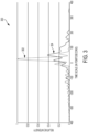
FIG. 3 is a plot showing example intensities incident upon a last diffraction grating in a pulse compressor of a pulse amplification system. -
FIG. 4 is a flow diagram showing an example process for amplifying chirped optical pulses. - CHEN X ET AL: "1-mJ, sub-5-fs carrier-envelope phase-locked pulses", APPLIED PHYSICS B ; LASERS AND OPTICS, SPRINGER, BERLIN, DE, vol. 99, no. 1-2, 1 December 2009 (2009-12-01), pages 149-157, XP019801464, ISSN: 1432-0649 describes the routine generation of sub-5-fs laser pulses with 1-mJ energy and stable carrier-envelope phase at 1-kHz repetition rate, obtained by compressing the multi-mJ output from a phase-locked Ti:sapphire amplifier in a rare-gas-filled hollow fiber.
-
US20140166906 A1 describes an extreme ultra violet (EUV) generation device including a light source for outputting a laser beam, a pulse width compression system for compressing a pulse width of the laser beam, a gas cell for receiving the laser beam having the compressed pulse width incident from the pulse width compression system and generating EUV light, and a vacuum chamber housing the pulse width compression system and the gas cell. - In aspects of what is described here, a chirped pulse laser system (such as a chirped pulse amplifier (CPA)) includes a programmable optical dispersive filter (PODF) and a pulse compressor, among other components. The pulse compressor includes optical elements in a vacuum chamber (e.g., a chamber that operates at less than 10-3 Torr, less than 2 × 10⁻⁸ Torr, or another high vacuum pressure), and the optical elements define an optical path through the pulse compressor. In some implementations, the pulse compressor may be operated such that an optical signal in the optical path of the pulse compressor is below a critical power at which self-channeling effects may appear. The optical elements of the pulse compressor are arranged to compress the optical pulse, and include diffraction gratings and a dispersive mirror. In some examples, each diffraction grating has a ridged reflective surface and the dispersive mirror has a smooth reflective surface. Because the ridged nanostructure of the diffraction gratings makes them susceptible to field enhancement, the dispersive mirror's flat reflective surface may have a higher damage threshold relative to the diffraction gratings. The smooth reflective surface of the dispersive mirror can be formed by alternating layers of dielectric materials on a substrate (e.g., alternating layers of high- and low-index materials, such as Titanium dioxide (TiO2) and Silicon dioxide (SiO2), respectively). In some instances, the dispersive mirror is the last optical element in the optical path. In some instances, the dispersive mirror provides for second order dispersion (or group delay dispersion) of approximately (+/-)300 femtoseconds squared (fs2) for optical pulses with a duration of approximately 15-17 femtoseconds (fs).
- Aspects of the present disclosure may provide one or more advantages, in some implementations. For example, a dispersive mirror may better withstand high-intensity optical pulses found in a chirped pulse laser system compared to diffraction gratings (e.g., a dispersive mirror may have a damage threshold more than four (4) times greater than the damage threshold of a diffraction grating). Thus, in some aspects, the dispersive mirror may be used in a pulse compressor of a CPA to reduce the intensity and the damage threshold fluence incident upon one or more diffraction gratings (e.g., the last diffraction grating in an optical path in the pulse compressor) in the pulse compressor by an order of magnitude or more (e.g., by approximately forty percent (40%)). In addition, in some implementations, a wave plate may be used to modify the polarization of the optical pulse in a pulse compressor, which may reduce the damage threshold of the dispersive mirror in the pulse compressor. Compression of a high-power chirped pulse (e.g., from a Petawatt class laser system) may therefore be achieved with less degradation and more lifetime of the optical elements used in the pulse compressor, which may allow for an increased duty cycle or repetition rate of the system. In some aspects, a pulse compressor comprising a dispersive mirror may produce optical pulses having higher peak power, and may do so over the same or similar lifetime as previous systems with only diffraction gratings. In some aspects, a pulse compressor comprising a dispersive mirror may produce optical pulses having the same or similar peak power as previous systems with only diffraction gratings, but with smaller optical elements and therefore reduced costs (e.g., through reduced costs related to one or more of the diffraction gratings or other optical elements in the pulse compressor). In some aspects, the dispersive mirror and diffraction gratings of a pulse compressor may operate under high vacuum pressures (e.g., less than 10-3 Torr), reducing cumulative non-linear effects caused by certain types of media or combinations of media (e.g., air, Helium, glass, or combinations thereof). In some aspects, the pulse compressor may be configured to produce a transform-limited optical pulse with a negligible B-Integral. In some aspects, the pulse compressor may be configured to produce a single-cycle optical pulse.
-
FIG. 1 is a block diagram showing aspects of an examplepulse amplification system 100. In the example shown, thepulse amplification system 100 includes apulse generator 102, apulse stretcher 104, apulse amplifier 106, and apulse compressor 108. A pulse amplification system may include additional or different components. In some implementations, thepulse amplification system 100 amplifies broad-spectrum, short duration chirped optical pulses, such as, for example, optical pulses with a duration of less than 50 fs. The duration of the pulse may be measured as the full width of the pulse at half maximum intensity (FWHM). For instance, thepulse amplification system 100 may be configured to produce a pulse with a duration of approximately 15-17 fs with a peak power of approximately 100 TeraWatts (TW). - The
example pulse generator 102 generates anoptical pulse 103 for amplification by thepulse amplification system 100. In some implementations, theoptical pulse 103 is a Fourier transform limited (or transform-limited) optical pulse. In some implementations, thepulse generator 102 includes a femtosecond laser oscillator, such as, for example, a femtosecond Ti:sapphire laser. Thepulse generator 102 may include additional or different components. For example, in some implementations thepulse generator 102 includes a chirped pulse amplifier (CPA) in addition to a femtosecond laser oscillator. - The
example pulse stretcher 104 receives theoptical pulse 103 generated by thepulse generator 102, and stretches theoptical pulse 103 to produce the stretchedoptical pulse 105. The stretchedoptical pulse 105 may be a chirped optical pulse, with a frequency that is time dependent. The frequency of the stretchedoptical pulse 105 may increase with time (an up-chirped pulse) or decrease with time (a down-chirped pulse). Thepulse stretcher 104 stretches theoptical pulse 103 using one or more dispersive optical elements, such as diffraction gratings, optical glass with chromatic dispersion characteristics (e.g., SCHOTT SF57 glass). The dispersive optical elements of thepulse stretcher 104 cause the different wavelength components of theoptical pulse 103 to disperse spatially and temporally from one another while travelling through thepulse stretcher 104, causing the stretchedoptical pulse 105 to have a lower intensity (e.g., an intensity below the damage threshold of the pulse amplifier 106). The dispersive optical elements of thepulse stretcher 104 may positively or negatively disperse the chirped optical pulse received from thepulse generator 102. - In some implementations, the spectral phase of the optical signal produced by the
pulse stretcher 104 can be modified. For example, thepulse amplification system 100 may include a programmable optical dispersive filter (PODF) that modifies the spectral phase of the optical signal provided to thepulse amplifier 106. In some cases, an optical signal can be described in the frequency domain, for example, as
pulse compressor 108 has a flat spectral phase (with all frequency components having the same phase), or to modify the spectral phase of an optical signal such that the optical signal output from thepulse compressor 108 has another spectral phase profile. - In some implementations, the
example pulse stretcher 104 includes or is coupled to an acousto-optic programmable dispersive filter (AOPDF), which modifies the spectral phase of the stretchedoptical pulse 105 while travelling through the AOPDF. The spectral phase modification may be based on an acoustic signal received by the AOPDF. For instance, the AOPDF may include a piezoelectric medium having mechanical properties (e.g., mechanical stress) that are controlled by an applied acoustic signal and influence a spectral phase modification applied to the optical signal. The AOPDF may modify the spectral phase of the stretchedoptical pulse 105 such that thepulse compressor 108 produces an optical signal that has a flat spectral phase over the different wavelength components of the optical signal. In some instances, the AOPDF may be programmed based on properties of thepulse compressor 108. For example, the AOPDF may be programmed to modify the spectral phase of the optical signal based on the optical properties of dispersive optical elements in thepulse compressor 108. - The
example pulse amplifier 106 receives the stretchedoptical pulse 105 from thepulse stretcher 104, and increases the peak power of the stretched optical pulse. Theexample pulse amplifier 106 increases the power of the stretched optical pulse using one or more optical elements having a gain medium (e.g., Ti:sapphire) which transfers energy input to the gain medium (e.g., electrical energy) to the stretchedoptical pulse 105 to produce the amplifiedoptical pulse 107. In some implementations, thepulse amplifier 106 includes a multipass amplifier. - The
example pulse compressor 108 is a system of one or more components that receives the amplifiedoptical pulse 107 from thepulse amplifier 106, and compresses the amplifiedoptical pulse 107 using optical dispersion. Theexample pulse compressor 108 compresses the pulse using one or more dispersive optical elements, such as, for example, diffraction gratings or dispersive mirrors. In the example shown, the dispersive optical elements of thepulse compressor 108 cause an opposite magnitude dispersion of the optical pulse than the dispersive optical elements of thepulse stretcher 104. For example, where thepulse stretcher 104 positively disperses the optical pulse, thepulse compressor 108 negatively disperses the optical pulse. In some implementations, thepulse compressor 108 is configured to at least approximately cancel out the amount of dispersion imparted to the chirpedoptical pulse 103 by thepulse stretcher 104. In some implementations, thepulse compressor 108 includes a highly dispersive mirror (HDM) that has a smooth reflective surface and is composed of layers of dielectric materials. For example, in some implementations, the HDM includes alternating layers of high- and low-index dielectric materials, such as Titanium dioxide (TiO2) and Silicon dioxide (SiO2), respectively. In some implementations, the total physical thickness of the high-index material is approximately 4700 nm, while the total physical thickness of the low-index material is approximately 7700 m. Other materials and layer thickness can be used. -
FIG. 2 is a diagram showing aspects of an example chirped pulse amplifier (CPA)system 200. In the example shown, theCPA system 200 includes apulse generator 202, apulse stretcher 204, a programmable optical dispersive filter (PODF) 206, apulse amplifier 208, and apulse compressor 210. Like thepulse amplification system 100 ofFIG. 1 , theexample CPA system 200 amplifies broad-spectrum, short duration chirped optical pulses, such as, for example, those with durations of less than 50 fs. For instance, theCPA system 200 may be configured to produce an amplified optical pulse having a duration of approximately 15-17 fs, a spectrum of 730-870 nm, and peak power of approximately 100 TW. In some implementations, theCPA system 200 may be configured to generate single-cycle optical pulses. For instance, theCPA system 200 may be configured to produce an amplified optical pulse having a duration of approximately 2.66 fs at a wavelength of approximately 800 nm. - In the example shown, the
pulse generator 202 generates an optical pulse that is transmitted to thepulse stretcher 204. Theexample pulse generator 202 includes one or more components that generate a broad-spectrum ultrashort optical pulse. In some cases, thepulse generator 202 can produce Fourier transform limited ultrashort optical pulses. For example, thepulse generator 202 may generate an optical pulse having a duration of 15-17 fs and spectrum of 730-870 nm. In some implementations, theexample pulse generator 202 is implemented similar to thepulse generator 102 ofFIG. 1 . For instance, thepulse generator 202 may include a femtosecond laser oscillator, such as a femtosecond Ti:sapphire laser. - The
example pulse stretcher 204 includes one or more dispersive optical elements that stretch an optical signal as it traverses an optical path through thepulse stretcher 204. The dispersive optical elements of theexample pulse stretcher 204 temporally broaden the pulse by spatially dispersing the different wavelength components of the optical pulse received from thepulse generator 202. The dispersive optical elements may positively or negatively disperse the optical pulse. In some implementations, thepulse stretcher 204 is implemented similar to thepulse stretcher 104 ofFIG. 1 . For instance, thepulse stretcher 204 may include one or more diffraction gratings that act to disperse the optical pulse from thepulse generator 202. In the example shown, thepulse stretcher 204 receives the optical pulse from thepulse generator 202, stretches the optical pulse, and transmits the stretched optical pulse to thePODF 206. - The
example PODF 206 includes one or more components that modify the spectral phase of the optical pulse as it travels through thePODF 206. In some implementations, thePODF 206 includes an acousto-optic programmable dispersive filter (AOPDF), which receives an acoustic signal and modifies the spectral phase of an optical pulse travelling through the PODF based on the acoustic signal. In some implementations, thePODF 206 is implemented using a DAZZLER system available from FASTLITE. Another type of PODF may be used, and thePODF 206 may include additional or different components. In the example shown, thePODF 206 receives the stretched optical pulse from thepulse stretcher 204, modifies the spectral phase of the stretched optical pulse, and transmits the phase-modified optical pulse to thepulse amplifier 208. - The
example pulse amplifier 208 includes one or more components that increase the power of an optical pulse using one or more optical elements having a gain medium (e.g., Ti:sapphire), which transfers energy input to the gain medium (e.g., electrical energy) to the optical pulse. In some implementations, thepulse amplifier 208 includes a multipass amplifier. In the example shown, thepulse amplifier 208 receives the phase-modified optical pulse from thePODF 206, amplifies the optical pulse, and transmits the amplified optical pulse to thepulse compressor 210. - The
example pulse compressor 210 includes one or more dispersive optical elements that compress an optical signal as it traverses an optical path through thepulse compressor 210. The dispersive optical elements of theexample pulse compressor 210 temporally compress the pulse by spatially dispersing the different wavelength components of the optical pulse received from thepulse amplifier 208. In some implementations, the dispersive optical elements of thepulse compressor 210 are in a vacuum chamber. Theexample pulse compressor 210 includes anoptical inlet 211, afirst diffraction grating 212, asecond diffraction grating 213, a third diffraction grating 214 afourth diffraction grating 215, awave plate 216, adispersive mirror 217, and anoptical outlet 218. In some implementations, thepulse compressor 210 includes additional optical elements, such as, for example, one or more mirrors or thin optics between thefourth diffraction grating 215 and thedispersive mirror 217. In the example shown, thepulse compressor 210 receives the amplified optical pulse from thepulse amplifier 208 at theoptical inlet 211, compresses the amplified optical pulse, and transmits the compressed optical pulse to thechamber 230 from theoptical outlet 218. In some implementations, the optical pulse produced from theoptical outlet 218 is a transform-limited pulse. In some implementations, thepulse compressor 210 produces a transform-limited pulse with a negligible B-Integral. In some examples, the beam diameter of the optical pulse at theoutlet 218 is approximately 150 millimeters (mm); or thepulse compressor 210 may produce an optical signal having another beam diameter. In some implementations, theoptical inlet 211 comprises glass, while theoptical outlet 218 comprises an optical tunnel to thechamber 230. The optical tunnel of theoptical outlet 218 may be operated at a vacuum pressure, such as, for example, the vacuum pressure of the pulse compressor (e.g., less than 10-3 Torr). - The
example chamber 230 includes components that interact with the compressed optical pulse from theoptical outlet 218. In some implementations, thechamber 230 comprises a vacuum chamber operated at a vacuum pressure (e.g., less than 10-3 Torr). In some implementations, the vacuum chamber of thechamber 230 is operated at the same vacuum pressure as the vacuum chamber of thepulse compressor 210. For example, in some implementations, thechamber 230 includes crystalline materials or other elements that can be used to produce high-energy particles based on the optical pulse from thepulse compressor 210. For instance, thechamber 230 may produce a particle beam, a gamma ray beam, an x-ray beam or another type of output. As an example, thechamber 230 may be configured to produce a x-ray beam by Betatron, Compton, or K-alpha scattering. As another example, the chamber 120 may be configured to produce high duty cycle particle beams or radiation beams. - The diffraction gratings 212-215,
wave plate 216, and thedispersive mirror 217 define an optical path within thepulse compressor 210 that includes path portions 221-227. The optical path generally extends from theoptical inlet 211 to theoptical outlet 218 and includes the series of optical elements and path portions between respective pairs of the optical elements. The path portions 221-227 are regions of the vacuum chamber that reside between the optical elements in thepulse compressor 210, and during operation of thepulse compressor 210, the path portions 221-227 contain gas (e.g., air, Helium, or another gas) at vacuum pressure (e.g., in the range of 2 × 10⁻⁸ to 3 × 10⁻⁸ Torr). - The example diffraction gratings 212-215 and the
dispersive mirror 217 are arranged in thepulse compressor 210 such that they disperse the optical pulse in the optical path. The diffraction gratings 212-215 and thedispersive mirror 217 may impart positive or negative dispersion on the optical pulse, depending on the dispersion imparted by thepulse stretcher 204 in theexample CPA system 200. For example, where thepulse stretcher 204 positively disperses the optical pulse, thepulse compressor 210 negatively disperses the optical pulse. In some implementations, thepulse compressor 210 is configured to at least approximately cancel out the amount of dispersion imparted to the optical pulse by thepulse stretcher 204. In the example shown, the diffraction gratings 212-215 are arranged before thedispersive mirror 217 in the optical path. In some implementations, the diffraction gratings 212-215 may each have 1480 lines per millimeter (l/mm), and may be displaced from one another by 1 mm. Where the diffraction gratings 212-215 are displaced from one another by 1 mm, the diffraction gratings 212-215 may each induce a dispersion of 5500 fs2 and 11,000 fs3 onto an optical pulse in the optical path. - The
example wave plate 216 modifies a polarization of the optical pulse as it travels therethrough. For example, thewave plate 216 may modify the polarization of the optical pulse such that it is entirely s-polarized (e.g., by converting p-polarized components to s-polarized components of the optical pulse), which may impart less damage when incident upon thedispersive mirror 217. Thewave plate 216 may modify the polarization of the optical pulse in another manner, such as, for example, modifying the optical pulse to be circularly polarized. In some implementations, thewave plate 216 is a half-wave plate. In some implementations, thewave plate 216 is a quarter-wave plate. In some implementations, thewave plate 216 is a segmented wave plate (e.g., with a mosaic pattern) that creates radial-typed polarizations. In the example shown, thewave plate 216 is between the last diffraction grating 215 (the final diffraction grating in the optical path) and thedispersive mirror 217. Although theexample CPA system 200 includes onewave plate 216 as shown inFIG. 2 , thepulse compressor 210 may include no wave plates or may include additional wave plates. - The example diffraction gratings 212-215,
wave plate 216, anddispersive mirror 217 of thepulse compressor 210 reside in a vacuum chamber. In some implementations, one or more diffraction gratings (e.g., thediffraction gratings 212, 213) may reside outside of the vacuum chamber. The vacuum chamber may be configured to operate at a vacuum pressure of less than 10-3 Torr. For example, in some implementations, the diffraction gratings 212-215,wave plate 216, anddispersive mirror 217 reside in a vacuum chamber that operates at approximately 2.5 × 10⁻⁸ Torr (in the range of 2 × 10⁻⁸ to 3 × 10⁻⁸ Torr). By operating the optical elements in a vacuum chamber under vacuum pressure, non-linear effects caused by media in the optical path between the optical elements (e.g., air) may be reduced or avoided. In addition, in some implementations, the vacuum chamber may be configured to operate at a vacuum pressure that is based on the peak power of the optical pulses travelling in thepulse compressor 210. For example, the vacuum chamber of thepulse compressor 210 may be operated at a particular vacuum pressure such that the peak power of the optical pulses is below a critical power, and the optical pulses may avoid self-channeling effects while traversing the optical path through thepulse compressor 210. By operating the vacuum chamber of thepulse compressor 210 at vacuum pressures less than 10-3 Torr, the optical pulses produced by thepulse compressor 210 may have higher peak power. For example, in some instances, the optical pulse travelling in thepulse compressor 210 has a peak power of greater than 10 GigaWatts (GW) (which is approximately the critical power at which self-channeling effects appear for optical pulses in air at atmospheric pressure). The critical power at which self-channeling effects may appear can be described by the following equation:
- In the
example CPA system 200 ofFIG. 2 , the diffraction gratings 212-215 have a ridged reflective surface that define part of the optical path in thepulse compressor 210, while thedispersive mirror 217 has a smooth reflective surface that defines part of the optical path in thepulse compressor 210. Theexample dispersive mirror 217 can be implemented as a highly dispersive mirror (HDM) composed of layers of dielectric materials disposed on a substrate (e.g., silica or sapphire). In some implementations, thedispersive mirror 217 includes alternating layers of high- and low-index dielectric materials. In the example shown, the high-index material has a refractive index greater than 1.7; for example, Titanium dioxide (TiO2) having a refractive index of 2.5 may be used. In the example shown, the low-index material has a refractive index less than1.7; for example, Silicon dioxide (SiO2) having a refractive index of 1.45 may be used. In some implementations, the total physical thickness of the high-index dielectric material of thedispersive mirror 217 is approximately 4700 nm, while the total physical thickness of the low-index dielectric material of thedispersive mirror 217 is approximately 7700 m. In some implementations, thedispersive mirror 217 imparts a second order dispersion (or group delay dispersion) of approximately (+/-)300 fs2 onto an optical pulse with a spectrum centered around 800 nm (e.g., having a spectrum of 730-870 nm). In some implementations, the second order dispersion characteristics of thedispersive mirror 217 are wavelength dependent. -
FIG. 3 is aplot 300 showing example intensities incident upon a last diffraction grating in a pulse compressor of a pulse amplification system. Theexample plot 300 includestraces trace 302.Trace 302 is an example measurement of temporal intensity incident upon a last diffraction grating in a pulse compressor of a pulse amplification system, such as a CPA, where the pulse amplification system does not include a dispersive mirror in the optical path of the pulse compressor.Trace 304 is an example measurement of temporal intensity incident upon a last diffraction grating in a pulse compressor of a pulse amplification system, such as a CPA, that includes a dispersive mirror as the last optical element in the optical path of the pulse compressor. For instance, the measurements oftrace 304 may be indicative of the intensity incident upondiffraction grating 215 ofFIG. 2 relative to a system similar to what is shown inFIG. 2 except that it does not include thedispersive mirror 217. As indicated by theplot 300, the inclusion of adispersive mirror 217 as the last optical element in the optical path of thepulse compressor 210 may reduce the intensity of the optical pulse incident upon thediffraction grating 215, which may allow for a longer lifespan and increased duty cycle of the diffraction grating. -
FIG. 4 is a flow diagram showing anexample process 400 for amplifying chirped optical pulses. Theprocess 400 may be implemented using thepulse amplification system 100 ofFIG. 1 , theCPA system 200 ofFIG. 2 or another system. In some implementations, one or more operations of theprocess 400 are performed by optical elements or other components operating under high vacuum pressure. For example, the diffraction gratings and dispersive mirror that compress the optical pulse at 450 may reside in a vacuum chamber that operates at pressures below 10-3 Torr. - At 410, a chirped optical pulse is generated using a femtosecond oscillator, such as a femtosecond Ti:sapphire laser. At 420, the optical pulse is stretched using one or more diffraction gratings. The diffraction gratings may impart either positive or negative dispersion upon the optical pulse. At 430, the spectral phase of the stretched optical pulse is modified using a programmable optical dispersive filter (PODF). The PODF may be implemented using an AOPDF, which modifies the spectral phase of the optical pulse based on a received acoustic signal. At 440, the optical pulse is amplified using a multipass amplifier. At 450, the optical pulse is compressed using one or more diffraction gratings and dispersive mirrors. The diffraction gratings and dispersive mirrors may impart either positive or negative dispersion upon the optical pulse, which is the opposite of the dispersion imparted upon the optical pulse at 420. For instance, where positive dispersion is imparted upon the optical pulse at 420, negative dispersion may be imparted upon the optical pulse at 450.
- In a general aspect of the examples described here, a chirped pulse laser system includes a pulse compressor with a dispersive mirror.
- In a first example, a chirped pulse laser system includes a programmable optical dispersive filter (PODF) and a pulse compressor that receives an optical pulse based on an output of the PODF. The PODF is operable to modify a spectral phase of optical pulses. The pulse compressor includes optical elements in a vacuum chamber. The optical elements define an optical path through the pulse compressor, and are arranged to disperse the optical pulse in the optical path. The optical elements include diffraction gratings and a dispersive mirror. The dispersive mirror has a smooth reflective surface that defines a portion of the optical path.
- Implementations of the first example may include one or more of the following features. The dispersive mirror may include one or more dielectric materials on a substrate. The dispersive mirror may include alternating layers of a high-index dielectric material and a low-index dielectric material. The high-index material may include Titanium dioxide (TiO2) and the low-index material may include Silicon dioxide (SiO2). The total thickness of the layers of Titanium dioxide (TiO2) may be approximately 4700 nm, and the total thickness of the layers of Silicon dioxide (SiOz) may be approximately 7700 nm. The dispersive mirror may be operable to impart a second order dispersion of approximately (+/-)300 fs2 to the optical pulse.
- Implementations of the first example may include one or more of the following features. The vacuum chamber may be configured to operate at pressures less than 10-3 Torr. The PODF may include an acousto-optic programmable dispersive filter (AOPDF), which may be operable to modify the spectral phase of an optical signal based on an acoustic signal received by the PODF. The optical elements of the pulse compressor may include a wave plate operable to modify a polarization of the optical pulse. The wave plate may reside in the optical path between the dispersive mirror and the last diffraction grating. The diffraction gratings may be arranged before the dispersive mirror in the optical path.
- Implementations of the first example may include one or more of the following features. The system may include a pulse generator, a pulse stretcher that receives an output of the pulse generator, and a pulse amplifier that receives an output of the PODF. The pulse stretcher may include one or more optical elements that disperse optical pulses, and the pulse amplifier may be operable to increase a power of optical pulses. The pulse compressor may be arranged to receive an output of the pulse amplifier. The pulse generator may include a femtosecond laser oscillator.
- Implementations of the first example may include one or more of the following features. The optical elements may define an optical path between an optical inlet of the pulse compressor and an optical outlet of the pulse compressor. The pulse compressor may include a first diffraction grating arranged to receive the optical pulse from the optical inlet, a second diffraction grating arranged to receive the optical pulse from the first diffraction grating, a third diffraction grating arranged to receive the optical pulse from the second diffraction grating, and a fourth diffraction grating arranged to receive the optical pulse from the third diffraction grating. The dispersive mirror may be arranged to provide the optical pulse to the optical outlet.
- In a second example, compressing a chirped optical pulse includes modifying a spectral phase of an optical pulse by operation of a programmable optical dispersive filter (PODF) and compressing the optical pulse by operation of a pulse compressor. The pulse compressor includes optical elements in a vacuum chamber. The optical elements define an optical path in the pulse compressor, and are arranged to disperse the optical pulse in the optical path. The optical elements include diffraction gratings and a dispersive mirror. The dispersive mirror has a smooth reflective surface that defines a portion of the optical path.
- Implementations of the second example may include one or more of the following features. The dispersive mirror may include one or more dielectric materials on a substrate. The dispersive mirror may include alternating layers of a high-index dielectric material and a low-index dielectric material. The high-index material may include Titanium dioxide (TiO2) and the low-index material may include Silicon dioxide (SiO2). The total thickness of the layers of Titanium dioxide (TiO2) may be approximately 4700 nm, and the total thickness of the layers of Silicon dioxide (SiO2) may be approximately 7700 nm. The dispersive mirror may be operable to impart a second order dispersion of approximately (+/-)300 fs2 to the optical pulse. The vacuum chamber may be operated at pressures less than 10-3 Torr.
- Implementations of the second example may include one or more of the following features. The method may include amplifying the optical pulse by operation of a pulse amplifier before compressing the optical pulse. The method may include generating the optical pulse using a femtosecond laser oscillator. The method may include stretching the optical pulse by operation of a pulse stretcher before modifying the spectral phase of the optical pulse. The pulse stretcher may include dispersive optical elements. The PODF may include an acousto-optic programmable dispersive filter (AOPDF), and the method may include modifying the spectral phase of the optical pulse base on an acoustic signal received by the AOPDF.
- Implementations of the second example may include one or more of the following features. Compressing the optical pulse may include compressing the optical pulse by operation of the diffraction gratings before compressing the optical pulse by operation of the dispersive mirror. Compressing the optical pulse may include modifying a polarization of the optical pulse using a wave plate. Compressing the optical pulse may include imparting a second order dispersion of approximately (+/-)300 fs2 to the optical pulse by operation of the dispersive mirror. The compressed optical pulse may have a peak power of greater than 10 GigaWatts (GW).
- Implementations of the second example may include one or more of the following features. The optical elements may define an optical path between an optical inlet of the pulse compressor and an optical outlet of the pulse compressor. The pulse compressor may include a first diffraction grating arranged to receive the optical pulse from the optical inlet, a second diffraction grating arranged to receive the optical pulse from the first diffraction grating, a third diffraction grating arranged to receive the optical pulse from the second diffraction grating, and a fourth diffraction grating arranged to receive the optical pulse from the third diffraction grating. The dispersive mirror may be arranged to provide the optical pulse to the optical outlet.
- While this specification contains many details, these should not be understood as limitations on the scope of what may be claimed, but rather as descriptions of features specific to particular examples. Certain features that are described in this specification or shown in the drawings in the context of separate implementations can also be combined. Conversely, various features that are described or shown in the context of a single implementation can also be implemented in multiple embodiments separately or in any suitable subcombination.
- Similarly, while operations are depicted in the drawings in a particular order, this should not be understood as requiring that such operations be performed in the particular order shown or in sequential order, or that all illustrated operations be performed, to achieve desirable results. In certain circumstances, multitasking and parallel processing may be advantageous. Moreover, the separation of various system components in the implementations described above should not be understood as requiring such separation in all implementations, and it should be understood that the described program components and systems can generally be integrated together in a single product or packaged into multiple products.
- A number of embodiments have been described. Nevertheless, it will be understood that various modifications can be made. Accordingly, other embodiments are within the scope of the following claims.
Claims (18)
- A chirped pulse laser system (200) comprising:a programmable optical dispersive filter, PODF, (206) operable to modify a spectral phase of optical pulses; anda pulse compressor (210) that receives an optical pulse based on an output of the PODF (206), and in response, produces a transform-limited optical pulse, the pulse compressor comprising optical elements in a vacuum chamber, the optical elements defining an optical path (221-227) through the pulse compressor, the optical elements arranged to disperse the optical pulse in the optical path, the optical elements comprising diffraction gratings (212-215) and a dispersive mirror (217), the dispersive mirror having a smooth reflective surface that defines a portion of the optical path.
- The system of claim 1, wherein the vacuum chamber is configured to operate at pressures less than 10-3 Torr.
- The system of claim 1 or 2, wherein the PODF (206) comprises an acousto-optic programmable dispersive filter, AOPDF.
- The system of any one of claims 1 to 3, wherein the optical elements comprise a wave plate (216) operable to modify a polarization of the optical pulse, and preferably the wave plate resides in the optical path (225-226) between the dispersive mirror (217) and the last diffraction grating (215) in the optical path.
- The system of claim 1 or 2, wherein the diffraction gratings (212-215) are arranged before the dispersive mirror (217) in the optical path.
- The system of claim 1 or 2, comprising:a pulse generator (202);a pulse stretcher (204) that receives an output of the pulse generator (202), the pulse stretcher comprising one or more optical elements that disperse optical pulses; anda pulse amplifier (208) that receives an output of the PODF (206), the pulse amplifier operable to increase a power of optical pulses; andwherein the pulse compressor (210) is arranged to receive an output of the pulse amplifier (208), and preferably the pulse generator (202) comprises a femtosecond laser oscillator.
- The system of claim 1 or 2,wherein the optical elements define an optical path (221-227) between an optical inlet (211) of the pulse compressor (210) and an optical outlet (218) of the pulse compressor;wherein the pulse compressor includes:a first diffraction grating (212) arranged to receive the optical pulse from the optical inlet (211),a second diffraction grating (213) arranged to receive the optical pulse from the first diffraction grating (212),a third diffraction grating (214) arranged to receive the optical pulse from the second diffraction grating (213), anda fourth diffraction grating (215) arranged to receive the optical pulse from the third diffraction grating (214); andwherein the dispersive mirror (217) is arranged to provide the optical pulse to the optical outlet (218).
- A method of compressing a chirped optical pulse comprising:modifying a spectral phase of an optical pulse by operation of a programmable optical dispersive filter, PODF, (206); andcompressing the optical pulse by operation of a pulse compressor (210) to produce a transform-limited optical pulse, the pulse compressor comprising optical elements in a vacuum chamber, the optical elements defining an optical path (221-227) in the pulse compressor, the optical elements arranged to disperse the optical pulse in the optical path, the optical elements comprising diffraction gratings (212-215) and a dispersive mirror (217), the dispersive mirror having a smooth reflective surface that defines a portion of the optical path.
- The method of claim 8, comprising operating the vacuum chamber at a pressure less than 10-3 Torr.
- The method of claim 8, wherein the PODF (206) comprises an acousto-optic programmable dispersive filter, AOPDF, and the method comprises modifying the spectral phase of the optical pulse based on an acoustic signal received by the AOPDF.
- The method of claim 8, comprising amplifying the optical pulse by operation of a pulse amplifier (208) before compressing the optical pulse, and preferably, generating the optical pulse using a femtosecond laser oscillator.
- The method of claim 8, comprising stretching the optical pulse by operation of a pulse stretcher (204) before modifying the spectral phase of the optical pulse, the pulse stretcher comprising dispersive optical elements.
- The method of any one of claims 8-12, wherein compressing the optical pulse comprises compressing the optical pulse by operation of four diffraction gratings (212-215) before compressing the optical pulse by operation of the dispersive mirror (217).
- The method of any one of claims 8-12, wherein compressing the optical pulse comprises modifying a polarization of the optical pulse using a wave plate (216).
- The method of any one of claims 8-12, wherein the compressed optical pulse has a peak power greater than 10 GigaWatts (GW).
- The system of claim 1 or the method of claim 8, wherein the dispersive mirror (217) comprises one or more dielectric materials on a substrate, and preferably the dielectric materials comprise alternating layers of a high-index dielectric material and a low-index dielectric material, and preferably the high-index material comprises titanium dioxide (TiO2) and the low-index material comprises silicon dioxide (SiO2).
- The system of any one of claims 1-7, wherein each of the diffraction gratings (212-215) is a reflective diffraction grating.
- The method of any one of claims 8-15, wherein each of the diffraction gratings (212-215) is a reflective diffraction grating.
Applications Claiming Priority (2)
| Application Number | Priority Date | Filing Date | Title |
|---|---|---|---|
| US201562269183P | 2015-12-18 | 2015-12-18 | |
| PCT/CA2016/051485 WO2017100930A1 (en) | 2015-12-18 | 2016-12-15 | Pulse compression in chirped pulse laser systems |
Publications (4)
| Publication Number | Publication Date |
|---|---|
| EP3391481A1 EP3391481A1 (en) | 2018-10-24 |
| EP3391481A4 EP3391481A4 (en) | 2019-08-14 |
| EP3391481C0 EP3391481C0 (en) | 2025-02-26 |
| EP3391481B1 true EP3391481B1 (en) | 2025-02-26 |
Family
ID=59055551
Family Applications (1)
| Application Number | Title | Priority Date | Filing Date |
|---|---|---|---|
| EP16874208.8A Active EP3391481B1 (en) | 2015-12-18 | 2016-12-15 | Pulse compression in chirped pulse laser systems |
Country Status (4)
| Country | Link |
|---|---|
| US (1) | US10396522B2 (en) |
| EP (1) | EP3391481B1 (en) |
| CA (1) | CA3010979C (en) |
| WO (1) | WO2017100930A1 (en) |
Families Citing this family (6)
| Publication number | Priority date | Publication date | Assignee | Title |
|---|---|---|---|---|
| JP7505979B2 (en) * | 2017-09-07 | 2024-06-25 | ローレンス・リバモア・ナショナル・セキュリティ・エルエルシー | SYMMETRIC OUT-OF-PLANE DIFFRACTION GRINDINGS AND METHODS - Patent |
| AU2019298263B2 (en) * | 2018-07-06 | 2024-05-02 | Institut National De La Recherche Scientifique | Method and system of laser-driven intense x-ray photons imaging |
| CN111555101A (en) * | 2020-05-20 | 2020-08-18 | 中国科学技术大学 | Device for generating laser pulse train with adjustable frequency chirp |
| CN112366497B (en) * | 2020-11-23 | 2023-05-12 | 中国科学院上海光学精密机械研究所 | Laser pulse width compression system with preset space chirp |
| WO2024010847A1 (en) * | 2022-07-06 | 2024-01-11 | Analog Photonics LLC | Managing laser system optical characteristics |
| KR102937190B1 (en) * | 2023-10-19 | 2026-03-23 | 대한민국(방위사업청장) | Helium-filled pulse compressor for femtosecond laser |
Citations (1)
| Publication number | Priority date | Publication date | Assignee | Title |
|---|---|---|---|---|
| US20120327963A1 (en) * | 2011-06-21 | 2012-12-27 | The Government Of The United States Of America, As Represented By The Secretary Of The Navy | Quasi-remote laser pulse compression and generation of radiation and particle beams |
Family Cites Families (6)
| Publication number | Priority date | Publication date | Assignee | Title |
|---|---|---|---|---|
| US20050111515A1 (en) * | 2003-11-21 | 2005-05-26 | Jean-Claude Diels | Aerodynamic window for generating and characterizing a filament |
| WO2006089681A2 (en) * | 2005-02-22 | 2006-08-31 | Gesellschaft für Schwerionenforschung mbH | Method for increasing the laser damage threshold of diffraction grids |
| JP5177969B2 (en) * | 2006-07-12 | 2013-04-10 | 浜松ホトニクス株式会社 | Optical amplifier |
| US20120113513A1 (en) * | 2010-10-22 | 2012-05-10 | The Regents Of The University Of Colorado, A Body Corporate | Self-cleaning of optical surfaces in low-pressure reactive gas environments in advanced optical systems |
| KR20140079616A (en) * | 2012-12-17 | 2014-06-27 | 삼성전자주식회사 | Extreme Ultra Violet(EUV) generation device |
| EP2953214B1 (en) * | 2013-01-31 | 2018-12-19 | Shimadzu Corporation | Diffraction grating for laser pulse compression and laser device |
-
2016
- 2016-12-15 US US16/061,564 patent/US10396522B2/en active Active
- 2016-12-15 CA CA3010979A patent/CA3010979C/en active Active
- 2016-12-15 EP EP16874208.8A patent/EP3391481B1/en active Active
- 2016-12-15 WO PCT/CA2016/051485 patent/WO2017100930A1/en not_active Ceased
Patent Citations (1)
| Publication number | Priority date | Publication date | Assignee | Title |
|---|---|---|---|---|
| US20120327963A1 (en) * | 2011-06-21 | 2012-12-27 | The Government Of The United States Of America, As Represented By The Secretary Of The Navy | Quasi-remote laser pulse compression and generation of radiation and particle beams |
Non-Patent Citations (1)
| Title |
|---|
| CAVALIERI A L ET AL: "Intense 1.5-cycle near infrared laser waveforms and their use for the generation of ultra-broadband soft-x-ray harmonic continua", NEW JOURNAL OF PHYSICS, INSTITUTE OF PHYSICS PUBLISHING, BRISTOL, GB, vol. 9, no. 7, 1 July 2007 (2007-07-01), pages 242 - 242, XP020122821, ISSN: 1367-2630, DOI: 10.1088/1367-2630/9/7/242 * |
Also Published As
| Publication number | Publication date |
|---|---|
| CA3010979A1 (en) | 2017-06-22 |
| US20190115711A1 (en) | 2019-04-18 |
| EP3391481C0 (en) | 2025-02-26 |
| US10396522B2 (en) | 2019-08-27 |
| EP3391481A4 (en) | 2019-08-14 |
| EP3391481A1 (en) | 2018-10-24 |
| CA3010979C (en) | 2023-08-29 |
| WO2017100930A1 (en) | 2017-06-22 |
Similar Documents
| Publication | Publication Date | Title |
|---|---|---|
| Li et al. | Further development of the short‐pulse Petawatt laser: trends, technologies, and bottlenecks | |
| US10396522B2 (en) | Pulse compression in chirped pulse laser systems | |
| US9678405B2 (en) | System and method for high-intensity ultrashort pulse compression | |
| CN106329302A (en) | Dual-chirp optical parameter amplification method and device for broadband laser pumping | |
| CN104254952A (en) | Generating ultrashort laser pulses based on two-stage pulse processing | |
| US6603600B2 (en) | Chirped pulse amplification method and apparatus | |
| Mironov et al. | 100 J-level pulse compression for peak power enhancement | |
| WO2018045898A1 (en) | Supercontinuum coherent light source | |
| Mukhin et al. | Design of the front-end system for a subexawatt laser of the XCELS facility | |
| US8774240B2 (en) | Frequency-drift amplification device for a pulsed laser | |
| US20190372300A1 (en) | Generation of VUV, EUV, and X-ray Light Using VUV-UV-VIS Lasers | |
| CN111697426A (en) | Device for generating frequency comb by adopting sulfur hexafluoride stimulated Raman | |
| Fu et al. | Dual-chirped optical parametric amplification: a method for generating super-intense mid-infrared few-cycle pulses | |
| Sung et al. | 5-Hz, 150-TW Ti: sapphire laser with high spatiotemporal quality | |
| Diels et al. | Air filaments and vacuum | |
| Romanov et al. | Configuration model of a grating pair pulse compressor | |
| JP2013535835A (en) | Pulse laser amplifier using frequency drift | |
| EP4645612A1 (en) | Compressor for pulsed laser radiation | |
| Molchanov et al. | Adaptive optical delay lines for femtosecond laser pulses shaping | |
| CN100442134C (en) | Femtosecond pulse compression device | |
| Ahmad | Development of an optically synchronized seed source for a high-power few-cycle OPCPA system | |
| Jocher et al. | 23 fs pulses at 250 W of average power from a FCPA with solid core nonlinear compression | |
| Babin et al. | Ionization spectrum transformation and compression of powerful femtosecond laser pulses in experiments on the propagation in gas-filled dielectric capillaries | |
| Tajalli et al. | Towards characterization and compression of 1.5 octaves spectrum spanning from VIS to IR from two-color pumped OPCPA system | |
| KR20250025010A (en) | System and method for compressing optical pulses |
Legal Events
| Date | Code | Title | Description |
|---|---|---|---|
| STAA | Information on the status of an ep patent application or granted ep patent |
Free format text: STATUS: THE INTERNATIONAL PUBLICATION HAS BEEN MADE |
|
| PUAI | Public reference made under article 153(3) epc to a published international application that has entered the european phase |
Free format text: ORIGINAL CODE: 0009012 |
|
| STAA | Information on the status of an ep patent application or granted ep patent |
Free format text: STATUS: REQUEST FOR EXAMINATION WAS MADE |
|
| 17P | Request for examination filed |
Effective date: 20180716 |
|
| AK | Designated contracting states |
Kind code of ref document: A1 Designated state(s): AL AT BE BG CH CY CZ DE DK EE ES FI FR GB GR HR HU IE IS IT LI LT LU LV MC MK MT NL NO PL PT RO RS SE SI SK SM TR |
|
| AX | Request for extension of the european patent |
Extension state: BA ME |
|
| DAV | Request for validation of the european patent (deleted) | ||
| DAX | Request for extension of the european patent (deleted) | ||
| A4 | Supplementary search report drawn up and despatched |
Effective date: 20190715 |
|
| RIC1 | Information provided on ipc code assigned before grant |
Ipc: H01S 3/00 20060101AFI20190709BHEP Ipc: H01S 3/10 20060101ALI20190709BHEP |
|
| STAA | Information on the status of an ep patent application or granted ep patent |
Free format text: STATUS: EXAMINATION IS IN PROGRESS |
|
| 17Q | First examination report despatched |
Effective date: 20200727 |
|
| GRAP | Despatch of communication of intention to grant a patent |
Free format text: ORIGINAL CODE: EPIDOSNIGR1 |
|
| STAA | Information on the status of an ep patent application or granted ep patent |
Free format text: STATUS: GRANT OF PATENT IS INTENDED |
|
| INTG | Intention to grant announced |
Effective date: 20241014 |
|
| GRAS | Grant fee paid |
Free format text: ORIGINAL CODE: EPIDOSNIGR3 |
|
| GRAA | (expected) grant |
Free format text: ORIGINAL CODE: 0009210 |
|
| STAA | Information on the status of an ep patent application or granted ep patent |
Free format text: STATUS: THE PATENT HAS BEEN GRANTED |
|
| AK | Designated contracting states |
Kind code of ref document: B1 Designated state(s): AL AT BE BG CH CY CZ DE DK EE ES FI FR GB GR HR HU IE IS IT LI LT LU LV MC MK MT NL NO PL PT RO RS SE SI SK SM TR |
|
| REG | Reference to a national code |
Ref country code: GB Ref legal event code: FG4D |
|
| REG | Reference to a national code |
Ref country code: CH Ref legal event code: EP |
|
| REG | Reference to a national code |
Ref country code: DE Ref legal event code: R096 Ref document number: 602016091399 Country of ref document: DE |
|
| REG | Reference to a national code |
Ref country code: IE Ref legal event code: FG4D |
|
| U01 | Request for unitary effect filed |
Effective date: 20250325 |
|
| U07 | Unitary effect registered |
Designated state(s): AT BE BG DE DK EE FI FR IT LT LU LV MT NL PT RO SE SI Effective date: 20250331 |
|
| PG25 | Lapsed in a contracting state [announced via postgrant information from national office to epo] |
Ref country code: RS Free format text: LAPSE BECAUSE OF FAILURE TO SUBMIT A TRANSLATION OF THE DESCRIPTION OR TO PAY THE FEE WITHIN THE PRESCRIBED TIME-LIMIT Effective date: 20250526 |
|
| PG25 | Lapsed in a contracting state [announced via postgrant information from national office to epo] |
Ref country code: PL Free format text: LAPSE BECAUSE OF FAILURE TO SUBMIT A TRANSLATION OF THE DESCRIPTION OR TO PAY THE FEE WITHIN THE PRESCRIBED TIME-LIMIT Effective date: 20250226 |
|
| PG25 | Lapsed in a contracting state [announced via postgrant information from national office to epo] |
Ref country code: ES Free format text: LAPSE BECAUSE OF FAILURE TO SUBMIT A TRANSLATION OF THE DESCRIPTION OR TO PAY THE FEE WITHIN THE PRESCRIBED TIME-LIMIT Effective date: 20250226 |
|
| PG25 | Lapsed in a contracting state [announced via postgrant information from national office to epo] |
Ref country code: NO Free format text: LAPSE BECAUSE OF FAILURE TO SUBMIT A TRANSLATION OF THE DESCRIPTION OR TO PAY THE FEE WITHIN THE PRESCRIBED TIME-LIMIT Effective date: 20250526 Ref country code: IS Free format text: LAPSE BECAUSE OF FAILURE TO SUBMIT A TRANSLATION OF THE DESCRIPTION OR TO PAY THE FEE WITHIN THE PRESCRIBED TIME-LIMIT Effective date: 20250626 |
|
| PG25 | Lapsed in a contracting state [announced via postgrant information from national office to epo] |
Ref country code: HR Free format text: LAPSE BECAUSE OF FAILURE TO SUBMIT A TRANSLATION OF THE DESCRIPTION OR TO PAY THE FEE WITHIN THE PRESCRIBED TIME-LIMIT Effective date: 20250226 |
|
| PG25 | Lapsed in a contracting state [announced via postgrant information from national office to epo] |
Ref country code: GR Free format text: LAPSE BECAUSE OF FAILURE TO SUBMIT A TRANSLATION OF THE DESCRIPTION OR TO PAY THE FEE WITHIN THE PRESCRIBED TIME-LIMIT Effective date: 20250527 |
|
| PG25 | Lapsed in a contracting state [announced via postgrant information from national office to epo] |
Ref country code: SM Free format text: LAPSE BECAUSE OF FAILURE TO SUBMIT A TRANSLATION OF THE DESCRIPTION OR TO PAY THE FEE WITHIN THE PRESCRIBED TIME-LIMIT Effective date: 20250226 |
|
| PG25 | Lapsed in a contracting state [announced via postgrant information from national office to epo] |
Ref country code: CZ Free format text: LAPSE BECAUSE OF FAILURE TO SUBMIT A TRANSLATION OF THE DESCRIPTION OR TO PAY THE FEE WITHIN THE PRESCRIBED TIME-LIMIT Effective date: 20250226 |
|
| PG25 | Lapsed in a contracting state [announced via postgrant information from national office to epo] |
Ref country code: SK Free format text: LAPSE BECAUSE OF FAILURE TO SUBMIT A TRANSLATION OF THE DESCRIPTION OR TO PAY THE FEE WITHIN THE PRESCRIBED TIME-LIMIT Effective date: 20250226 |
|
| U20 | Renewal fee for the european patent with unitary effect paid |
Year of fee payment: 10 Effective date: 20251110 |
|
| PLBE | No opposition filed within time limit |
Free format text: ORIGINAL CODE: 0009261 |
|
| STAA | Information on the status of an ep patent application or granted ep patent |
Free format text: STATUS: NO OPPOSITION FILED WITHIN TIME LIMIT |
|
| REG | Reference to a national code |
Ref country code: CH Ref legal event code: L10 Free format text: ST27 STATUS EVENT CODE: U-0-0-L10-L00 (AS PROVIDED BY THE NATIONAL OFFICE) Effective date: 20260107 |
|
| PGFP | Annual fee paid to national office [announced via postgrant information from national office to epo] |
Ref country code: GB Payment date: 20251030 Year of fee payment: 10 |
|
| 26N | No opposition filed |
Effective date: 20251127 |
|
| PG25 | Lapsed in a contracting state [announced via postgrant information from national office to epo] |
Ref country code: MC Free format text: LAPSE BECAUSE OF FAILURE TO SUBMIT A TRANSLATION OF THE DESCRIPTION OR TO PAY THE FEE WITHIN THE PRESCRIBED TIME-LIMIT Effective date: 20250226 |
|
| REG | Reference to a national code |
Ref country code: CH Ref legal event code: H13 Free format text: ST27 STATUS EVENT CODE: U-0-0-H10-H13 (AS PROVIDED BY THE NATIONAL OFFICE) Effective date: 20260723 |