EP3391016B1 - Probennehmer - Google Patents
Probennehmer Download PDFInfo
- Publication number
- EP3391016B1 EP3391016B1 EP16809832.5A EP16809832A EP3391016B1 EP 3391016 B1 EP3391016 B1 EP 3391016B1 EP 16809832 A EP16809832 A EP 16809832A EP 3391016 B1 EP3391016 B1 EP 3391016B1
- Authority
- EP
- European Patent Office
- Prior art keywords
- sampler
- quick connect
- sample
- valve
- connect valve
- Prior art date
- Legal status (The legal status is an assumption and is not a legal conclusion. Google has not performed a legal analysis and makes no representation as to the accuracy of the status listed.)
- Active
Links
Images


Classifications
-
- G—PHYSICS
- G01—MEASURING; TESTING
- G01N—INVESTIGATING OR ANALYSING MATERIALS BY DETERMINING THEIR CHEMICAL OR PHYSICAL PROPERTIES
- G01N1/00—Sampling; Preparing specimens for investigation
- G01N1/02—Devices for withdrawing samples
- G01N1/10—Devices for withdrawing samples in the liquid or fluent state
- G01N1/20—Devices for withdrawing samples in the liquid or fluent state for flowing or falling materials
- G01N1/2035—Devices for withdrawing samples in the liquid or fluent state for flowing or falling materials by deviating part of a fluid stream, e.g. by drawing-off or tapping
- G01N2001/2064—Devices for withdrawing samples in the liquid or fluent state for flowing or falling materials by deviating part of a fluid stream, e.g. by drawing-off or tapping using a by-pass loop
-
- G—PHYSICS
- G01—MEASURING; TESTING
- G01N—INVESTIGATING OR ANALYSING MATERIALS BY DETERMINING THEIR CHEMICAL OR PHYSICAL PROPERTIES
- G01N1/00—Sampling; Preparing specimens for investigation
- G01N1/02—Devices for withdrawing samples
- G01N1/10—Devices for withdrawing samples in the liquid or fluent state
- G01N1/20—Devices for withdrawing samples in the liquid or fluent state for flowing or falling materials
- G01N1/2035—Devices for withdrawing samples in the liquid or fluent state for flowing or falling materials by deviating part of a fluid stream, e.g. by drawing-off or tapping
- G01N2001/2071—Removable sample bottle
Definitions
- the present invention is related to the sampling of fluids, for example, in the context of control or supervision of an industrial process involving the use and/or production of at least one fluid, such as, for example, formaldehyde.
- Another frequent problem related to the collection of samples is how to avoid contamination of the sample.
- DE-29504081-U1 Another example is taught by DE-29504081-U1 , which teaches a sampler comprising an elongated body provided with what appears to be some kind of quick connect valves in correspondence with its ends, for connecting the sample to some kind of conduit, whereby the sampler will establish a bypass to said conduit, so that the fluid in the conduit can flow into the sampler.
- the device is held by a kind of handle comprising two elongated elements, so that the user does not have to hold the elongated body that contains the sample, which can be at a high temperature. Also, one of the two elongated elements is displaceable in relation to the other, and this movement is used to disconnect the sampler from the conduit.
- US-2002/0170364-A1 and US-5251495-A disclose arrangements for collecting samples including quick-connects arranged after valves placed in correspondence with the axial ends of the container intended to receive the respective sample.
- a first aspect of the invention is defined in claim 1.
- the first aspect of the invention relates to a sampler, that is, a device for obtaining or collecting a sample, especially for obtaining a sample of a fluid (for example, a gas or a liquid), from an installation in, for example, a factory, warehouse, laboratory, or other industrial plant in which fluids are produced, stored and/or used.
- the sampler comprises:
- the two quick connect valve members can be used to connect the sampler to a device from which a sample is to be obtained, such as a tank or a conduit, such as a conduit for transporting a fluid within a factory or plant.
- the two quick connect valve members for example, two so-called female quick connect valve members- can be mated to corresponding complementary quick connect valve members -for example, so-called male quick connect valve members- extending from for example a tank or conduit, thereby allowing quick, simple and dry connection and disconnection of the sampler, establishing and interrupting a by-pass conduit along which the fluid can flow from the tank or conduit, into the chamber, and back into the tank or conduit.
- the body is a substantially elongated body, the body having a first end and a second end. In some embodiments, the body has a length of more than 10, 20 or 30 cm, and/or less than 150, 100 or 60 cm. In some embodiments, the body has a maximum width or diameter of less than 10, 8, 6, 5, 4, 3, 2 or 1 cm. For example, it has been found to be practical to use a sampler having a length of more than 20 and less than 80 cm, and a diameter of less than 8 cm and preferably less than 6 cm (including the insulating cover, if any), in order to facilitate manual handling of the sampler.
- the sample outlet valve is placed at one end of the elongated body.
- the two quick connect valve members are placed between the vent valve and the sample outlet valve.
- the body has a generally cylindrical configuration.
- the body is basically a metal tube with a vent valve at one of its ends or close to it, and a sample outlet valve at the other end.
- the presence of a sample outlet valve in correspondence with an end of the body makes it possible to easily discharge a sample from the chamber into, for example, a container or other device or apparatus, for example, for analysis of the sample. Deposition of the sample into the device or container can be carried out without any need for any specific and complex arrangements for removing the sample from the chamber of the sampler.
- the fluid can exit the sample outlet valve by gravity and/or by the force exerted by another fluid supplied through the vent valve (for example, in some cases an inert fluid such as nitrogen can be used).
- another fluid supplied through the vent valve for example, in some cases an inert fluid such as nitrogen can be used.
- the vent valve facilitates the exit of the sample, for example, by allowing air or other fluids to enter the chamber at a point that is distal from the first end.
- the quick connect valve members are generally arranged to be in a closed state when they are not connected to the mating quick connect valve members, as known in the art.
- the tank or conduit can be provided (for example, by welding, screwing, clamping, or in any other suitable way) with a supplementary member featuring two quick connect valve members complementary to those of the sample, thereby allowing the sampler to be easily coupled to the tank or conduit, so that the fluid in the tank or conduit can enter the chamber of the sampler.
- a supplementary member featuring two quick connect valve members complementary to those of the sample, thereby allowing the sampler to be easily coupled to the tank or conduit, so that the fluid in the tank or conduit can enter the chamber of the sampler.
- conventional conduits or tanks can be adapted to be compatible with the use of the sampler of the invention.
- the remaining part of the sample can be re-introduced into the tank or conduit by re-connecting the sampler to the tank or conduit.
- This can be advantageous to avoid the problem of how to deal with a portion of a sample that is not needed for the analysis.
- the sample is a fluid that represents a health risk or that, for other reasons, should not simply be poured into a sink or otherwise dispensed with.
- the costs involved with handling this kind of sometimes toxic waste can be high.
- the possibility of re-introducing the fluid into the conduit or tank can be very advantageous.
- the sampler can remain connected to the tank or conduit for long periods of time and, for example, it can remain connected to the tank or conduit during operation of the installation, and only be removed when a sample of the fluid is desired.
- the vent valve is placed in correspondence with the second end of the body.
- air or an inert gas can be let into the chamber at the second end, facilitating evacuation of the sample.
- cleaning of the chamber can be performed by letting a fluid pass between the vent valve and the sample outlet valve.
- an inert gas or other fluid can be introduced through the vent valve, to create an inert atmosphere inside the chamber, and/or to remove traces of previous samples.
- the quick connect valve members are arranged between the first end and the second end of the body, and the quick connect valve members extend substantially radially from the body.
- the sampler further comprising a vent tube extending from the vent valve, for example, extending from and/or coupled to the vent valve.
- a vent tube can be useful to direct any substance exiting the vent valve away from the location where the user can be expected to have, for example, his or her face.
- any fluid or other substance that exits the vent valve for example, due to erroneous operation -such as due to opening of the vent valve when the sample is being collected- or other accidents, can be directed to an area where harm to the user is not likely to take place.
- vent tube can also be used to facilitate the injection of a fluid into the chamber, for example, for injecting an inert gas or fluid into the chamber, for example, prior to collecting a sample, or in order to help to eject a sample from the chamber, and/or to minimize the risk of contamination of the sample.
- the vent tube is rigid, and in other embodiments the vent tube is flexible.
- the vent tube has a length that is larger than 80% of the largest dimension of the body, for example, in the case of an elongated body, larger than 80% of the distance between the first end of the body and the second end of the body.
- the exit opening of the vent tube can be placed relatively far away from the vent valve, for example, adjacent to the sample output valve.
- a relatively long vent tube can also facilitate the connection between the sampler and a source of, for example, inert gas.
- the quick connect valve members extend substantially radially from the body, that is, substantially perpendicularly to a longitudinal axis of the body, in parallel with each other.
- This can facilitate the quick connection of the sampler to a device such as a tank or conduit housing or conveying a fluid, a sample of which is to be taken: the sampler can be placed in parallel with the relevant wall or section of the device, and then connected to it by simply moving the sampler in parallel with the axes of the quick connect valve members, towards the mating quick connect valve members.
- each quick connect valve member comprises a release member including, for example, a slidably arranged sleeve or similar, arranged to be displaced in the radial direction (taking the body as the reference, that is, in an axial direction if the quick connect valve member itself is taken as the reference) for releasing the quick connect valve member from a mating quick connect valve member of the device from which a sample is to be obtained. It has been found that this can facilitate the release of the sampler from the external device, such as from a tank or conduit, after collecting the sample: it is easy for a user to displace the release members in the radial direction, pushing them or pulling them with the fingers of the user, while at the same time holding the sampler with the hands.
- a release member including, for example, a slidably arranged sleeve or similar, arranged to be displaced in the radial direction (taking the body as the reference, that is, in an axial direction if the quick connect valve member itself is taken as the reference) for releasing the
- female quick connect valve members featuring this kind of radially displaceable sleeve -that is, radially displaceable in relation to the body of the sampler when the quick connect valve member extends radially from the body of the sampler, but axially displaceable in relation to the quick release valve member itself- are the female quick release members of at least some MCB couplings available from Staubli International AG.
- the sampler is configured (including sized and shaped) so that a human user can grip the body with two hands, and at the same time displace the release member of one of the quick connect valve members with two fingers of one hand, and displace the release member of the other quick connect valve member with two fingers of the other hand.
- the release members can easily be pulled towards the body of the sampler while the sampler is being held. One single person can carry out the quick disconnect while safely holding the sampler with his or her hands.
- the quick connect valve members are dry disconnect valve members. Dry disconnect valves are known in the art and useful to prevent any fluid from exiting in a non-desired manner when the sampler is being connected to or disconnected from a device, such as a tube or a tank, from which the sample is to be taken.
- the means for selectively setting the sample outlet valve into a closed or into an open state includes a rotary member or a push member for opening and closing the sample outlet valve, and wherein the sample outlet valve is preferably biased towards the closed state, thereby reducing the risk that the valve accidentally remains in an open state.
- the sample outlet valve can be a needle drain valve, which the user can operate by turning a member provided at the side of the valve.
- resilient means such as a spring or similar are incorporated for biasing the valve towards the closed state.
- the means for selectively setting the vent valve into a closed or into an open state includes a rotary member or a push member for opening and closing the vent valve, and wherein the vent valve is preferably biased towards the closed state, thereby reducing the risk that the valve accidentally remains in an open state.
- resilient means such as a spring or similar are incorporated for biasing the valve towards the closed state.
- the body is at least partly covered by an insulating material.
- the body can be made of a heat conductive material, such as a metal, for example, stainless steel, aluminum, or any other suitable material.
- an insulating material for example, a polymer material.
- the insulating cover is a removable cover (for example, with a Velcro closure or any other suitable closure), thereby allowing for easy replacement of the cover, for example, in order to adapt the sampler to a specific use, to give it a color according to a corporate color code, etc.
- a material having a high friction coefficient to minimize the risk that the sampler will slip while being manipulated by the user.
- the insulating material may be neoprene, with excellent anti-slip properties and generally compatible with the skin of human beings.
- each of the two quick connect valve members defines a conduit between a distal opening of the respective quick connect valve member and the chamber, wherein said conduit has a substantially circular cross section with a diameter of not less than 3mm at any position between the distal opening and the chamber when the quick connect valve member is mated to a complementary quick connect valve member, with the valve in an open state.
- the sampler further comprises a rupture disc arranged to be triggered when the pressure within the sampler exceeds a certain threshold.
- the rupture disc can break and provide for pressure relief by allowing fluid to exit from the sampler in a relatively controlled manner, reducing the risk of severe damage to the sampler and/or to a user of the sampler in the case of overpressure within the sampler during, for example, sampling or when fluid is injected through the vent tube.
- the rupture disc is positioned in correspondence with the second end of the body, for example, between the vent valve and the body.
- the rupture disc can in some embodiments be an independent member that is connected to the rest of the sampler via a threaded connection.
- a further aspect of the invention relates to a system comprising a sampler as described above, wherein the system further comprises at least one supplementary member featuring two quick connect valve members complementary to the quick connect valve members of the sampler, the supplementary member being configured for attachment, for example, by welding, screwing, clamping or in any other way, to a tank or conduit, such as in correspondence with a hole or opening in the tank or conduit, so as to allow the sampler to be coupled to the tank or conduit, so that fluid in the tank or conduit can enter the chamber of the sampler.
- a tank or conduit such as in correspondence with a hole or opening in the tank or conduit, so as to allow the sampler to be coupled to the tank or conduit, so that fluid in the tank or conduit can enter the chamber of the sampler.
- kits comprising a sampler and one or more supplementary members adapted for use with the sampler can be commercialized, and/or the supplementary members can be commercialized to allow an owner of a sampler to adapt an installation for housing and/or conveying fluids so that the sampler can be used with that installation.
- One advantage of providing this kind of supplementary member is that the purchaser can be sure that the complementary quick connect valve members are compatible with the sampler and placed at the exactly correct distance from each other to allow the sampler to be adequately coupled to them, for example, for the purpose of collecting a sample.
- adaptation of the installation can be carried out easily, by merely adding the supplementary member to the installation in correspondence with a hole or opening in a tank or conduit, without requiring precision work by the person in charge of the adaptation.
- the supplementary member can comprise additional fluid path cut-off means to make sure that no fluid will accidentally exit the quick connect valve members.
- a further aspect of the invention relates to a method of obtaining a sample of a fluid, comprising connecting a sampler as described above to a device from which a sample is to be obtained, by connecting the quick connect valve members of the sampler to corresponding quick connect valve members of the device from which a sample is to be obtained, by pushing the sampler towards the device from which a sample is to be obtained. That is, a simple push action can be enough to carry out the connection between the sampler and the device from which a sample is to be taken.
- the method further comprises removing the sampler after obtaining the sample, by performing a disconnect operation including displacing a release member associated with one of the quick connect valve members with one or more fingers of one hand, and displacing a release member associated with the other quick connect valve members with one or more fingers of another hand, while holding the sampler with both hands.
- a further aspect of the invention relates to a method of introducing a substance into a fluid housed in a device such as a conduit or tank, comprising the steps of:
- the fluid comprises formaldehyde, phenol, Vinyl Acetate Monomer and/or methanol.
- formaldehyde due to the characteristics of for example formaldehyde and considering the conditions under which it is often handled, stored and transported in for example factories or other installations, a sampler as described above can be especially useful for manipulating this kind of substances, in an easy manner and with minimized risk for the operator.
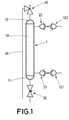
- Figure 1 schematically illustrates a sampler in accordance with an embodiment of the invention, comprising an elongated, substantially cylindrical, body 1 with a schematically illustrated internal chamber 1A, namely, an internal cavity of the body 1.
- Two quick connect valve members 21, 22 extend from the body 1. They extend radially in relation to the longitudinal axis of the body.
- These quick connect valve members namely, in this embodiment, female quick connect valve members, for example, the female parts of stainless steel Stäubli ® MCB couplings, are intended to connect the body to the device from which a sample is to be obtained, such as a tank or tube, by means of complementary male quick connect valve members 121, 122, such as the male parts of the stainless steel Stäubli ® MCB couplings.
- the sampler comprises a sample outlet valve 30 in correspondence with a first end 11 of the body 1, and a vent valve 40 in correspondence with a second end of the body 1.
- a vent tube 45 extends from the vent valve 40, and has a distal end placed in the vicinity of the sample outlet valve 30.
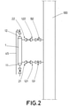
- Figure 2 illustrates the sampler connected to a pipe or conduit 100, through which a fluid can flow.
- the female quick connect valve members 21 and 22 are coupled to the corresponding male quick connect valve members 121 and 122, which, in turn, are connected to the conduit 100 via additional safety cut-off valves 131, 132.
- additional cut-off valves are not strictly necessary, as the male quick connect valve members 121, 122 will in any case be closed when they are not connected to the female quick connect valve members 21, 22, but they are sometimes preferred for increased safety.
- the sampler constitutes a bypass to the conduit 100, and part of the fluid flowing through the conduit will flow through this bypass, for example, from the conduit 100 through the valve members 122 and 22, into the chamber of the body 1, out through the valve members 21 and 121, and back into the conduit, or the other way around, depending on the direction of the fluid in the conduit.
- a sample of the fluid flowing through the conduit 100 will enter the chamber 1A of the body 1 of the sampler, and the sampler can then be disconnected from the male quick connect valve members 121 and 122, thereby removing the sample, that can then be taken to another location, for example, for analysis of the sample.
- the remaining part of the fluid may optionally be re-introduced into the conduit by re-connecting the sampler to the conduit.
- an inert fluid Prior to connecting the sampler to the conduit, an inert fluid can in some cases be introduced through the vent tube, to reduce the risk of contamination of the sample. Also, in some cases, an inert fluid can be introduced through the vent tube when the sample is removed, likewise to reduce the risk of contamination.
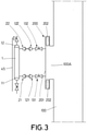
- Figure 3 illustrates an arrangement similar to the one of figure 2 , but including a supplementary member 200 comprising a base 201 and, extending from said base, two portions each comprising a safety cut-off valve 131, 132 and a male quick connect valve member 121, 122.
- the supplementary member 200 has its base 201 attached to the conduit 100 by welds 202.
- a supplementary member 200 comprising the male quick connect valve members 121, 122 can be advantageous in that it facilitates the adaptation of an existing installation to allow samples to be collected using a sampler: instead of installing the individual male quick connect valve members in an existing pipe or conduit, an operation that may require an eye for detail by the person handling the installation in order to make sure that the two male quick connect valve members will be at the exactly right distance from each other to allow the sampler to be correctly coupled to the conduit, a pre-manufactured supplementary member 200 can be used, that can be purchased from, for example, the entity producing and/or commercializing the sampler. This supplementary member can then simply be clamped or welded to an existing pipe or conduit, in correspondence with an opening 100A in the conduit.
- it can be welded onto the conduit.
- it can be screwed onto, for example, a flange existing in the conduit.
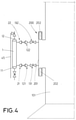
- Figure 4 illustrates an analogous arrangement, but with the supplementary member 200 welded to an opening in a tank 101.
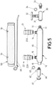
- Figure 5 illustrates the components used for making the sampler in accordance with an embodiment of the invention. It can be seen how the sampler comprises a substantially cylindrical body 1 with four threaded portions 13-16 with openings where a fluid can enter and/or exit the body.
- a first threaded portion 13 features an external thread and is arranged to be inserted into the sample outlet valve 30, in this case a needle valve which comprises a main valve portion 31 with a valve actuation member 32 for opening and closing the valve, and an outlet tip portion 33 which is screwed into the distal end of the main valve portion 31.
- a gasket 34 is provided between the main valve portion 31 and the tip portion 33 to prevent leakage.
- a second threaded portion 14 and a third threaded portion 15 both feature external threads by means of which the female quick connect valve members 21 and 22, respectively, are screwed onto the body 1.
- Both female quick connect valve members 21 and 22 feature a respective sleeve 21A and 22A, axially displaceable in relation to the respective quick connect valve member 21 and 22, that is, radially displaceable in relation to the longitudinal axis of the body 1.
- these sleeves will move towards the body and back again when the female quick connect valve members are pushed against respective male quick connect valve members, locking the sampler onto the male quick connect valve members.
- the sleeves 21A and 22A first have to be displaced towards the body 1, an action that can be carried out manually by a user.
- a fourth threaded portion 16 featuring an internal thread is used for connection of the vent valve 40, a gasket 43 being provided to prevent leakage.
- the vent valve 40 includes a knob 41 for opening and closing the vent valve, and an outlet portion 42 to which a vent tube 45 can be connected.
- An insulating neoprene cover 50 is likewise shown in figure 5 , with two openings 51 to accommodate the female quick connect valve members 21 and 22.
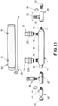
- FIG 11 An alternative embodiment further including a rupture disc 46 is shown in figure 11 .
- the rupture disc is positioned in correspondence with the second end 12 of the body 1.
- a T-shaped connector 47 is situated between the threaded portion 16 and the vent valve 40, and the rupture disc is screwed into an opening in the T-shaped connector.
- the rupture disc can be arranged to be triggered to break and release pressure when the pressure inside the sampler exceeds a certain threshold, thereby providing for increased safety during sampling and, for example, when a fluid is injected through the vent tube 45.
- the illustrated arrangement is just an example of how the rupture disc can be arranged.
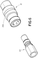
- Figure 6 schematically illustrates the male 121 and female 21 quick connect valve members (namely, Stäubli ® MCB couplings) that can be used in accordance with an embodiment of the invention.
- the sleeve 21A is to be displaced towards the body 1 in order to release the male quick connect valve member 121 from the female quick connect valve member 21.
- Figure 7 schematically illustrates how a user can hold and manipulate a sampler in accordance with an embodiment of the invention, with one hand 1000.
- Figure 8 schematically illustrates how a user can grip, with both hands, a sampler in accordance with an embodiment of the invention, attached to two male quick connect valve members 121 and 122.
- the user while gripping the sampler with the palm of the hand and the thumb, uses two fingers 1001 and 1002 of each hand to displace the sleeves 21A and 22A, thereby allowing the female quick connect valve member 21 and 22 to be unlocked from the corresponding male quick connect valve member 121 and 122, respectively. That is, the user, for obtaining a sample, can simply push the sampler onto the male quick connect valve members, whereby the male quick connect valve members will basically snap fit into the female quick connect valve members.
- the user then simply has to use one or two fingers of each hand for unlocking the female quick connect valve members from the male quick connect valve members by displacing the sleeve, whereafter the sampler can be withdrawn from the male quick connect valve members.
- Figure 9 schematically illustrates the process of collecting a sample using a sampler in accordance with an embodiment of the invention, comprising the following steps:
- Figure 10 schematically illustrates the process of introducing a substance into a device such as a tank or conduit, comprising the steps of:
Landscapes
- Life Sciences & Earth Sciences (AREA)
- Hydrology & Water Resources (AREA)
- Physics & Mathematics (AREA)
- Health & Medical Sciences (AREA)
- Chemical & Material Sciences (AREA)
- Analytical Chemistry (AREA)
- Biochemistry (AREA)
- General Health & Medical Sciences (AREA)
- General Physics & Mathematics (AREA)
- Immunology (AREA)
- Pathology (AREA)
- Sampling And Sample Adjustment (AREA)
Claims (15)
- Ein Probenehmer, umfassend:einen Körper (1) mit einer innere Kammer (1A) zur Aufnahme einer Probe eines Fluids;ein Probenauslassventil (30), das Mittel umfasst, um das Probenauslassventil selektiv in einen geschlossenen oder einen offenen Zustand zu versetzen;ein Entlüftungsventil (40), das Mittel umfasst, um das Entlüftungsventil selektiv in einen geschlossenen oder einen offenen Zustand zu versetzen; wobei der Probenehmer ferner gekennzeichnet ist durchzwei Schnellverbindungsventilelemente (21, 22), die sich von dem Körper (1) aus erstrecken, um den Körper (1) mit einem Gerät zu verbinden, von der eine Probe zu erhalten ist, wobei die beiden Schnellverbindungsventilelemente (21, 22) zwischen dem Entlüftungsventil (40) und dem Probenauslassventil (30) angeordnet sind;wobei sich die Schnellverbindungsventilelemente (21, 22) im Wesentlichen radial vom Körper (1) aus und parallel zueinander erstrecken.
- Der Probenehmer nach Anspruch 1, wobei der Körper (1) ein länglicher Körper ist, wobei der Körper ein erstes Ende (11) und ein zweites Ende (12) hat, und wobei das Probenauslassventil (30) in Übereinstimmung mit dem ersten Ende (11) des Körpers (1) angeordnet ist.
- Der Probenehmer nach Anspruch 2, wobei das Entlüftungsventil (40) in Übereinstimmung mit dem zweiten Ende (12) des Körpers angeordnet ist.
- Der Probenehmer gemäß Anspruch 3, wobei die Schnellverbindungsventilelemente (21, 22) zwischen dem ersten Ende und dem zweiten Ende des Körpers angeordnet sind, und wobei sich die Schnellverbindungsventilelemente (21, 22) im Wesentlichen radial vom Körper erstrecken.
- Der Probenehmer nach einem der vorhergehenden Ansprüche, ferner umfassend ein Entlüftungsrohr (45), das sich von dem Entlüftungsventil (40) erstreckt.
- Der Probenehmer nach Anspruch 5, wobei der Körper (1) ein länglicher Körper mit einem ersten Ende (11) und einem zweiten Ende (12) ist, wobei das Entlüftungsrohr (45) eine Länge hat, die größer als 80 % des Abstands zwischen dem ersten Ende und dem zweiten Ende ist.
- Der Probenehmer gemäß einem der vorhergehenden Ansprüche, wobei jedes Schnellverbindungsventilelement (21, 22) ein Freigabeelement (21A, 22A) umfasst, das so beschaffen ist, dass es in der radialen Richtung verschoben werden kann, um das Schnellverbindungsventilelement von einem passenden Schnellverbindungsventilelement zu lösen.
- Der Probenehmer gemäß Anspruch 7, der so eingerichtet ist, dass ein menschlicher Benutzer den Körper (1) mit zwei Händen greifen kann und gleichzeitig das Freigabeelement (21A) eines der Schnellverbindungsventilelemente (21) mit zwei Fingern einer Hand verschieben kann und das Freigabeelement (22A) des anderen Schnellverbindungsventilelements (22A) mit zwei Fingern der anderen Hand verschieben kann.
- Der Probenehmer gemäß einem der vorhergehenden Ansprüche, wobei- die Schnellverbindungsventilelemente Trockentrennventilelemente sind, und/oder wobei- jedes der beiden Schnellverbindungsventilelemente (11, 12) eine Leitung zwischen einer distalen Öffnung des jeweiligen Schnellverbindungsventilelements und der Kammer (1A) definiert, wobei die Leitung einen im Wesentlichen kreisförmigen Querschnitt mit einem Durchmesser von nicht weniger als 3 mm an jeder Position zwischen der distalen Öffnung und der Kammer aufweist.
- Der Probenehmer gemäß einem der vorhergehenden Ansprüche, wobei- das Mittel, um das Probenauslassventil (30) selektiv in einen geschlossenen oder einen offenen Zustand zu versetzen, ein Drehelement oder ein Drückelement zum Öffnen und Schließen des Probenauslassventils enthält, und wobei das Probenauslassventil (30) in Richtung des geschlossenen Zustands vorgespannt ist,und/oder wobei- das Mittel, um das Entlüftungsventil (40) selektiv in einen geschlossenen oder einen offenen Zustand zu versetzen ein Drehelement oder ein Drückelement zum Öffnen und Schließen des Entlüftungsventils enthält, und wobei das Entlüftungsventil (40) in Richtung des geschlossenen Zustands vorgespannt ist.
- Der Probenehmer gemäß einem der vorhergehenden Ansprüche, wobei der Körper zumindest teilweise von einem Isoliermaterial (50) bedeckt ist.
- Der Probenehmer gemäß einem der vorhergehenden Ansprüche, ferner umfassend eine Berstscheibe (46), wobei die Berstscheibe optional zwischen dem Körper (1) und dem Entlüftungsventil (40) angeordnet ist.
- Ein System, umfassend einen Probenehmer gemäß einem der vorhergehenden Ansprüche, wobei das System ferner mindestens ein zusätzliches Element umfasst, das zwei Schnellverbindungsventilelemente aufweist, die komplementär zu den Schnellverbindungsventilelementen (21, 22) des Probenehmers sind, wobei das zusätzliche Element zur Befestigung an einem Tank oder einer Leitung eingerichtet ist, so dass der Probenehmer mit dem Tank oder der Leitung verbunden werden kann, so dass Fluid in dem Tank oder der Leitung in die Kammer des Probenehmers eintreten kann.
- Ein Verfahren zum Erhalten einer Probe eines Fluids, umfassend das Verbinden eines Probenehmers gemäß einem der Ansprüche 1-7, 9-12 mit einem Gerät, aus dem eine Probe erhalten werden soll, durch Verbinden der Schnellverbindungsventilelemente (21, 22) des Probenehmers mit entsprechenden Schnellverbindungsventilelementen des Geräts, aus dem eine Probe erhalten werden soll, durch Drücken des Probenehmers zu dem Gerät, aus dem eine Probe erhalten werden soll, wobei das Verfahren ferner das Entfernen des Probenehmers nach dem Erhalten der Probe umfasst, durch Durchführen eines Trennvorgangs, enthaltend das Verschieben eines Freigabeelements (21A), das einem der Schnellverbindungsventilelemente (21) zugeordnet ist, mit einem oder mehreren Fingern einer Hand und das Verschieben eines Freigabeelements (22A), das dem anderen Schnellverbindungsventilelement (22) zugeordnet ist, mit einem oder mehreren Fingern einer anderen Hand, während der Probenehmer mit beiden Händen gehalten wird.
- Ein Verfahren zum Einbringen einer Substanz in ein Fluid, das in einem Gerät aufgenommen ist, umfassend die folgenden Schritte:Einbringen der Substanz in einen Probenehmer gemäß einem der Ansprüche 1-12;Verbinden des Probenehmers mit dem Gerät unter Verwendung der Schnellverbindungsventilelemente des Probenehmers;Zirkulieren von Fluid von dem Gerät durch die Kammer (1A) des Probenehmers und zurück in das Gerät,wobei das Fluid optional Formaldehyd, Phenol, Vinylacetatmonomer und/oder Methanol umfasst.
Priority Applications (1)
| Application Number | Priority Date | Filing Date | Title |
|---|---|---|---|
| PL16809832T PL3391016T3 (pl) | 2015-12-17 | 2016-12-14 | Urządzenie próbkujące |
Applications Claiming Priority (2)
| Application Number | Priority Date | Filing Date | Title |
|---|---|---|---|
| EP15382636 | 2015-12-17 | ||
| PCT/EP2016/081086 WO2017102895A1 (en) | 2015-12-17 | 2016-12-14 | Sampler |
Publications (2)
| Publication Number | Publication Date |
|---|---|
| EP3391016A1 EP3391016A1 (de) | 2018-10-24 |
| EP3391016B1 true EP3391016B1 (de) | 2022-02-16 |
Family
ID=55072497
Family Applications (1)
| Application Number | Title | Priority Date | Filing Date |
|---|---|---|---|
| EP16809832.5A Active EP3391016B1 (de) | 2015-12-17 | 2016-12-14 | Probennehmer |
Country Status (6)
| Country | Link |
|---|---|
| EP (1) | EP3391016B1 (de) |
| ES (1) | ES2913116T3 (de) |
| MY (1) | MY199568A (de) |
| PL (1) | PL3391016T3 (de) |
| PT (1) | PT3391016T (de) |
| WO (1) | WO2017102895A1 (de) |
Families Citing this family (3)
| Publication number | Priority date | Publication date | Assignee | Title |
|---|---|---|---|---|
| EP4427014A1 (de) * | 2021-11-05 | 2024-09-11 | Global Holdings Midlands Limited | Vorrichtung zur entnahme von thermischen flüssigkeitsproben |
| EP4469202B1 (de) | 2022-01-25 | 2025-10-01 | Foresa Technologies, S.L.U. | Ionenaustauschverfahren zur entsäuerung einer wässrigen formaldehydlösung, und anlage zur durchführung des verfahrens |
| KR102719581B1 (ko) * | 2024-02-02 | 2024-10-21 | 주식회사 남흥 | 유체 샘플링 장치 |
Family Cites Families (3)
| Publication number | Priority date | Publication date | Assignee | Title |
|---|---|---|---|---|
| US5251495A (en) * | 1990-12-21 | 1993-10-12 | Ashland Oil, Inc. | Minimum emission closed loop sampling system for transportable containers |
| WO2002093133A2 (en) * | 2001-05-16 | 2002-11-21 | Akzo Nobel N.V. | Sampling of flammable liquefied gas |
| US9329106B2 (en) * | 2014-02-28 | 2016-05-03 | Uop Llc | Methods, apparatuses and kits for collecting chemical samples |
-
2016
- 2016-12-14 EP EP16809832.5A patent/EP3391016B1/de active Active
- 2016-12-14 WO PCT/EP2016/081086 patent/WO2017102895A1/en not_active Ceased
- 2016-12-14 PL PL16809832T patent/PL3391016T3/pl unknown
- 2016-12-14 PT PT168098325T patent/PT3391016T/pt unknown
- 2016-12-14 ES ES16809832T patent/ES2913116T3/es active Active
- 2016-12-14 MY MYPI2018702293A patent/MY199568A/en unknown
Also Published As
| Publication number | Publication date |
|---|---|
| WO2017102895A1 (en) | 2017-06-22 |
| MY199568A (en) | 2023-11-07 |
| PL3391016T3 (pl) | 2022-06-13 |
| PT3391016T (pt) | 2022-05-16 |
| ES2913116T3 (es) | 2022-05-31 |
| EP3391016A1 (de) | 2018-10-24 |
Similar Documents
| Publication | Publication Date | Title |
|---|---|---|
| EP3391016B1 (de) | Probennehmer | |
| US5431067A (en) | Closed loop liquid sampler and sampling system | |
| US5301560A (en) | Closed loop liquid sampler and sampling system | |
| JP5193168B2 (ja) | 媒体移送用の装置 | |
| CN101558258A (zh) | 阀组件和系统 | |
| JP6227366B2 (ja) | エアーツールをマニピュレータに接続するための装置及び方法 | |
| EP2361032B1 (de) | Fluidkonnektor zur schnellen entkopplung | |
| US8365617B2 (en) | Sampling device | |
| EP2054314B1 (de) | Austauschbare säule für ein system zur ausgabe einer unter druck stehenden flüssigkeit | |
| WO2010118099A2 (en) | Device for maintaining sterile integrity of connected fluid pathways | |
| JP2007218428A (ja) | シール装着工具 | |
| JP4384172B2 (ja) | クイック交換式カップリングを有するインライン型フィルタ、及びフィルタ | |
| EP3235441A1 (de) | Ausgabeeinheit mit vorbestimmter rotationssequenz | |
| US6852288B2 (en) | System for multiple sterile sample collection and isolation | |
| US9995658B2 (en) | Sampling point valve | |
| EP2798328B1 (de) | Benutzerseitig austauschbarer filter für gasprobenahmesystem | |
| JP6821661B2 (ja) | 例えば核酸を抽出するための機器から、少なくとも一つの生成物排出管を、当該生成物を受け取る手段に接続する装置、接続するための装置 | |
| JP2002502954A (ja) | 容器充填物のためのハウジング | |
| US20160320354A1 (en) | Device for extracting a volatile component | |
| TWI843923B (zh) | 用於移除系統之管件 | |
| US7437958B2 (en) | Sterile single use sampling device | |
| JP2014040738A (ja) | 送水装置 | |
| JP3172639U (ja) | チューブ端部拡径/リング挿入用装置 | |
| US7024956B2 (en) | Sensor ball valve safety interlock | |
| US20090183351A1 (en) | Sewer lateral cap puller |
Legal Events
| Date | Code | Title | Description |
|---|---|---|---|
| STAA | Information on the status of an ep patent application or granted ep patent |
Free format text: STATUS: UNKNOWN |
|
| STAA | Information on the status of an ep patent application or granted ep patent |
Free format text: STATUS: THE INTERNATIONAL PUBLICATION HAS BEEN MADE |
|
| PUAI | Public reference made under article 153(3) epc to a published international application that has entered the european phase |
Free format text: ORIGINAL CODE: 0009012 |
|
| STAA | Information on the status of an ep patent application or granted ep patent |
Free format text: STATUS: REQUEST FOR EXAMINATION WAS MADE |
|
| 17P | Request for examination filed |
Effective date: 20180619 |
|
| AK | Designated contracting states |
Kind code of ref document: A1 Designated state(s): AL AT BE BG CH CY CZ DE DK EE ES FI FR GB GR HR HU IE IS IT LI LT LU LV MC MK MT NL NO PL PT RO RS SE SI SK SM TR |
|
| AX | Request for extension of the european patent |
Extension state: BA ME |
|
| DAV | Request for validation of the european patent (deleted) | ||
| DAX | Request for extension of the european patent (deleted) | ||
| STAA | Information on the status of an ep patent application or granted ep patent |
Free format text: STATUS: EXAMINATION IS IN PROGRESS |
|
| 17Q | First examination report despatched |
Effective date: 20210521 |
|
| RIC1 | Information provided on ipc code assigned before grant |
Ipc: G01N 1/20 20060101AFI20210810BHEP |
|
| GRAP | Despatch of communication of intention to grant a patent |
Free format text: ORIGINAL CODE: EPIDOSNIGR1 |
|
| STAA | Information on the status of an ep patent application or granted ep patent |
Free format text: STATUS: GRANT OF PATENT IS INTENDED |
|
| INTG | Intention to grant announced |
Effective date: 20210917 |
|
| RAP3 | Party data changed (applicant data changed or rights of an application transferred) |
Owner name: FORESA, INDUSTRIAS QUIMICAS DEL NOROESTE, S.A.U. |
|
| GRAS | Grant fee paid |
Free format text: ORIGINAL CODE: EPIDOSNIGR3 |
|
| GRAA | (expected) grant |
Free format text: ORIGINAL CODE: 0009210 |
|
| STAA | Information on the status of an ep patent application or granted ep patent |
Free format text: STATUS: THE PATENT HAS BEEN GRANTED |
|
| AK | Designated contracting states |
Kind code of ref document: B1 Designated state(s): AL AT BE BG CH CY CZ DE DK EE ES FI FR GB GR HR HU IE IS IT LI LT LU LV MC MK MT NL NO PL PT RO RS SE SI SK SM TR |
|
| REG | Reference to a national code |
Ref country code: GB Ref legal event code: FG4D |
|
| REG | Reference to a national code |
Ref country code: CH Ref legal event code: EP |
|
| REG | Reference to a national code |
Ref country code: DE Ref legal event code: R096 Ref document number: 602016069187 Country of ref document: DE |
|
| REG | Reference to a national code |
Ref country code: AT Ref legal event code: REF Ref document number: 1469174 Country of ref document: AT Kind code of ref document: T Effective date: 20220315 |
|
| REG | Reference to a national code |
Ref country code: IE Ref legal event code: FG4D |
|
| REG | Reference to a national code |
Ref country code: PT Ref legal event code: SC4A Ref document number: 3391016 Country of ref document: PT Date of ref document: 20220516 Kind code of ref document: T Free format text: AVAILABILITY OF NATIONAL TRANSLATION Effective date: 20220509 |
|
| REG | Reference to a national code |
Ref country code: ES Ref legal event code: FG2A Ref document number: 2913116 Country of ref document: ES Kind code of ref document: T3 Effective date: 20220531 |
|
| REG | Reference to a national code |
Ref country code: LT Ref legal event code: MG9D |
|
| REG | Reference to a national code |
Ref country code: NL Ref legal event code: MP Effective date: 20220216 |
|
| REG | Reference to a national code |
Ref country code: AT Ref legal event code: MK05 Ref document number: 1469174 Country of ref document: AT Kind code of ref document: T Effective date: 20220216 |
|
| PG25 | Lapsed in a contracting state [announced via postgrant information from national office to epo] |
Ref country code: SE Free format text: LAPSE BECAUSE OF FAILURE TO SUBMIT A TRANSLATION OF THE DESCRIPTION OR TO PAY THE FEE WITHIN THE PRESCRIBED TIME-LIMIT Effective date: 20220216 Ref country code: RS Free format text: LAPSE BECAUSE OF FAILURE TO SUBMIT A TRANSLATION OF THE DESCRIPTION OR TO PAY THE FEE WITHIN THE PRESCRIBED TIME-LIMIT Effective date: 20220216 Ref country code: NO Free format text: LAPSE BECAUSE OF FAILURE TO SUBMIT A TRANSLATION OF THE DESCRIPTION OR TO PAY THE FEE WITHIN THE PRESCRIBED TIME-LIMIT Effective date: 20220516 Ref country code: NL Free format text: LAPSE BECAUSE OF FAILURE TO SUBMIT A TRANSLATION OF THE DESCRIPTION OR TO PAY THE FEE WITHIN THE PRESCRIBED TIME-LIMIT Effective date: 20220216 Ref country code: LT Free format text: LAPSE BECAUSE OF FAILURE TO SUBMIT A TRANSLATION OF THE DESCRIPTION OR TO PAY THE FEE WITHIN THE PRESCRIBED TIME-LIMIT Effective date: 20220216 Ref country code: HR Free format text: LAPSE BECAUSE OF FAILURE TO SUBMIT A TRANSLATION OF THE DESCRIPTION OR TO PAY THE FEE WITHIN THE PRESCRIBED TIME-LIMIT Effective date: 20220216 Ref country code: BG Free format text: LAPSE BECAUSE OF FAILURE TO SUBMIT A TRANSLATION OF THE DESCRIPTION OR TO PAY THE FEE WITHIN THE PRESCRIBED TIME-LIMIT Effective date: 20220516 |
|
| PG25 | Lapsed in a contracting state [announced via postgrant information from national office to epo] |
Ref country code: LV Free format text: LAPSE BECAUSE OF FAILURE TO SUBMIT A TRANSLATION OF THE DESCRIPTION OR TO PAY THE FEE WITHIN THE PRESCRIBED TIME-LIMIT Effective date: 20220216 Ref country code: FI Free format text: LAPSE BECAUSE OF FAILURE TO SUBMIT A TRANSLATION OF THE DESCRIPTION OR TO PAY THE FEE WITHIN THE PRESCRIBED TIME-LIMIT Effective date: 20220216 Ref country code: AT Free format text: LAPSE BECAUSE OF FAILURE TO SUBMIT A TRANSLATION OF THE DESCRIPTION OR TO PAY THE FEE WITHIN THE PRESCRIBED TIME-LIMIT Effective date: 20220216 |
|
| PG25 | Lapsed in a contracting state [announced via postgrant information from national office to epo] |
Ref country code: IS Free format text: LAPSE BECAUSE OF FAILURE TO SUBMIT A TRANSLATION OF THE DESCRIPTION OR TO PAY THE FEE WITHIN THE PRESCRIBED TIME-LIMIT Effective date: 20220617 |
|
| PG25 | Lapsed in a contracting state [announced via postgrant information from national office to epo] |
Ref country code: SM Free format text: LAPSE BECAUSE OF FAILURE TO SUBMIT A TRANSLATION OF THE DESCRIPTION OR TO PAY THE FEE WITHIN THE PRESCRIBED TIME-LIMIT Effective date: 20220216 Ref country code: SK Free format text: LAPSE BECAUSE OF FAILURE TO SUBMIT A TRANSLATION OF THE DESCRIPTION OR TO PAY THE FEE WITHIN THE PRESCRIBED TIME-LIMIT Effective date: 20220216 Ref country code: RO Free format text: LAPSE BECAUSE OF FAILURE TO SUBMIT A TRANSLATION OF THE DESCRIPTION OR TO PAY THE FEE WITHIN THE PRESCRIBED TIME-LIMIT Effective date: 20220216 Ref country code: EE Free format text: LAPSE BECAUSE OF FAILURE TO SUBMIT A TRANSLATION OF THE DESCRIPTION OR TO PAY THE FEE WITHIN THE PRESCRIBED TIME-LIMIT Effective date: 20220216 Ref country code: DK Free format text: LAPSE BECAUSE OF FAILURE TO SUBMIT A TRANSLATION OF THE DESCRIPTION OR TO PAY THE FEE WITHIN THE PRESCRIBED TIME-LIMIT Effective date: 20220216 Ref country code: CZ Free format text: LAPSE BECAUSE OF FAILURE TO SUBMIT A TRANSLATION OF THE DESCRIPTION OR TO PAY THE FEE WITHIN THE PRESCRIBED TIME-LIMIT Effective date: 20220216 |
|
| REG | Reference to a national code |
Ref country code: DE Ref legal event code: R097 Ref document number: 602016069187 Country of ref document: DE |
|
| PG25 | Lapsed in a contracting state [announced via postgrant information from national office to epo] |
Ref country code: AL Free format text: LAPSE BECAUSE OF FAILURE TO SUBMIT A TRANSLATION OF THE DESCRIPTION OR TO PAY THE FEE WITHIN THE PRESCRIBED TIME-LIMIT Effective date: 20220216 |
|
| PLBE | No opposition filed within time limit |
Free format text: ORIGINAL CODE: 0009261 |
|
| STAA | Information on the status of an ep patent application or granted ep patent |
Free format text: STATUS: NO OPPOSITION FILED WITHIN TIME LIMIT |
|
| 26N | No opposition filed |
Effective date: 20221117 |
|
| PG25 | Lapsed in a contracting state [announced via postgrant information from national office to epo] |
Ref country code: SI Free format text: LAPSE BECAUSE OF FAILURE TO SUBMIT A TRANSLATION OF THE DESCRIPTION OR TO PAY THE FEE WITHIN THE PRESCRIBED TIME-LIMIT Effective date: 20220216 |
|
| P01 | Opt-out of the competence of the unified patent court (upc) registered |
Effective date: 20230524 |
|
| P02 | Opt-out of the competence of the unified patent court (upc) changed |
Effective date: 20230605 |
|
| PG25 | Lapsed in a contracting state [announced via postgrant information from national office to epo] |
Ref country code: IT Free format text: LAPSE BECAUSE OF FAILURE TO SUBMIT A TRANSLATION OF THE DESCRIPTION OR TO PAY THE FEE WITHIN THE PRESCRIBED TIME-LIMIT Effective date: 20220216 |
|
| REG | Reference to a national code |
Ref country code: CH Ref legal event code: PL |
|
| GBPC | Gb: european patent ceased through non-payment of renewal fee |
Effective date: 20221214 |
|
| PG25 | Lapsed in a contracting state [announced via postgrant information from national office to epo] |
Ref country code: LU Free format text: LAPSE BECAUSE OF NON-PAYMENT OF DUE FEES Effective date: 20221214 |
|
| PG25 | Lapsed in a contracting state [announced via postgrant information from national office to epo] |
Ref country code: LI Free format text: LAPSE BECAUSE OF NON-PAYMENT OF DUE FEES Effective date: 20221231 Ref country code: IE Free format text: LAPSE BECAUSE OF NON-PAYMENT OF DUE FEES Effective date: 20221214 Ref country code: GB Free format text: LAPSE BECAUSE OF NON-PAYMENT OF DUE FEES Effective date: 20221214 Ref country code: CH Free format text: LAPSE BECAUSE OF NON-PAYMENT OF DUE FEES Effective date: 20221231 |
|
| PG25 | Lapsed in a contracting state [announced via postgrant information from national office to epo] |
Ref country code: HU Free format text: LAPSE BECAUSE OF FAILURE TO SUBMIT A TRANSLATION OF THE DESCRIPTION OR TO PAY THE FEE WITHIN THE PRESCRIBED TIME-LIMIT; INVALID AB INITIO Effective date: 20161214 |
|
| PG25 | Lapsed in a contracting state [announced via postgrant information from national office to epo] |
Ref country code: CY Free format text: LAPSE BECAUSE OF FAILURE TO SUBMIT A TRANSLATION OF THE DESCRIPTION OR TO PAY THE FEE WITHIN THE PRESCRIBED TIME-LIMIT Effective date: 20220216 |
|
| PG25 | Lapsed in a contracting state [announced via postgrant information from national office to epo] |
Ref country code: MK Free format text: LAPSE BECAUSE OF FAILURE TO SUBMIT A TRANSLATION OF THE DESCRIPTION OR TO PAY THE FEE WITHIN THE PRESCRIBED TIME-LIMIT Effective date: 20220216 |
|
| PG25 | Lapsed in a contracting state [announced via postgrant information from national office to epo] |
Ref country code: MC Free format text: LAPSE BECAUSE OF FAILURE TO SUBMIT A TRANSLATION OF THE DESCRIPTION OR TO PAY THE FEE WITHIN THE PRESCRIBED TIME-LIMIT Effective date: 20220216 |
|
| PG25 | Lapsed in a contracting state [announced via postgrant information from national office to epo] |
Ref country code: TR Free format text: LAPSE BECAUSE OF FAILURE TO SUBMIT A TRANSLATION OF THE DESCRIPTION OR TO PAY THE FEE WITHIN THE PRESCRIBED TIME-LIMIT Effective date: 20220216 Ref country code: MC Free format text: LAPSE BECAUSE OF FAILURE TO SUBMIT A TRANSLATION OF THE DESCRIPTION OR TO PAY THE FEE WITHIN THE PRESCRIBED TIME-LIMIT Effective date: 20220216 |
|
| PG25 | Lapsed in a contracting state [announced via postgrant information from national office to epo] |
Ref country code: MT Free format text: LAPSE BECAUSE OF FAILURE TO SUBMIT A TRANSLATION OF THE DESCRIPTION OR TO PAY THE FEE WITHIN THE PRESCRIBED TIME-LIMIT Effective date: 20220216 |
|
| PGFP | Annual fee paid to national office [announced via postgrant information from national office to epo] |
Ref country code: FR Payment date: 20240911 Year of fee payment: 9 |
|
| REG | Reference to a national code |
Ref country code: DE Ref legal event code: R081 Ref document number: 602016069187 Country of ref document: DE Owner name: FORESA TECHNOLOGIES, S.L.U., CALDAS DE REIS, ES Free format text: FORMER OWNER: FORESA, INDUSTRIAS QUIMICAS DEL NOROESTE, S.A.U., CALDAS DE REIS, PONTEVEDRA, ES |
|
| PG25 | Lapsed in a contracting state [announced via postgrant information from national office to epo] |
Ref country code: GR Free format text: LAPSE BECAUSE OF NON-PAYMENT OF DUE FEES Effective date: 20220216 |
|
| PG25 | Lapsed in a contracting state [announced via postgrant information from national office to epo] |
Ref country code: GR Free format text: LAPSE BECAUSE OF NON-PAYMENT OF DUE FEES Effective date: 20220216 |
|
| PGFP | Annual fee paid to national office [announced via postgrant information from national office to epo] |
Ref country code: BE Payment date: 20241227 Year of fee payment: 9 Ref country code: PL Payment date: 20241120 Year of fee payment: 9 |
|
| REG | Reference to a national code |
Ref country code: ES Ref legal event code: PC2A Owner name: FORESA TECHNOLOGIES S.L.U. Effective date: 20250217 |
|
| REG | Reference to a national code |
Ref country code: BE Ref legal event code: PD Owner name: FORESA TECHNOLOGIES, S.L.U.; ES Free format text: DETAILS ASSIGNMENT: CHANGE OF OWNER(S), ASSIGNMENT; FORMER OWNER NAME: FORESA, INDUSTRIAS QUIMICAS DEL NOROESTE, S.A.U. Effective date: 20241128 |
|
| PGFP | Annual fee paid to national office [announced via postgrant information from national office to epo] |
Ref country code: DE Payment date: 20241227 Year of fee payment: 9 |
|
| PGFP | Annual fee paid to national office [announced via postgrant information from national office to epo] |
Ref country code: ES Payment date: 20250103 Year of fee payment: 9 |
|
| PGFP | Annual fee paid to national office [announced via postgrant information from national office to epo] |
Ref country code: PT Payment date: 20250930 Year of fee payment: 10 |