EP3391010B1 - System und verfahren für verbesserte gleitlageroperationen - Google Patents
System und verfahren für verbesserte gleitlageroperationen Download PDFInfo
- Publication number
- EP3391010B1 EP3391010B1 EP16816510.8A EP16816510A EP3391010B1 EP 3391010 B1 EP3391010 B1 EP 3391010B1 EP 16816510 A EP16816510 A EP 16816510A EP 3391010 B1 EP3391010 B1 EP 3391010B1
- Authority
- EP
- European Patent Office
- Prior art keywords
- wear
- journal bearing
- engine
- bearing system
- combination
- Prior art date
- Legal status (The legal status is an assumption and is not a legal conclusion. Google has not performed a legal analysis and makes no representation as to the accuracy of the status listed.)
- Active
Links
Images




Classifications
-
- G—PHYSICS
- G01—MEASURING; TESTING
- G01M—TESTING STATIC OR DYNAMIC BALANCE OF MACHINES OR STRUCTURES; TESTING OF STRUCTURES OR APPARATUS, NOT OTHERWISE PROVIDED FOR
- G01M13/00—Testing of machine parts
- G01M13/04—Bearings
-
- G—PHYSICS
- G05—CONTROLLING; REGULATING
- G05B—CONTROL OR REGULATING SYSTEMS IN GENERAL; FUNCTIONAL ELEMENTS OF SUCH SYSTEMS; MONITORING OR TESTING ARRANGEMENTS FOR SUCH SYSTEMS OR ELEMENTS
- G05B15/00—Systems controlled by a computer
- G05B15/02—Systems controlled by a computer electric
-
- G—PHYSICS
- G06—COMPUTING OR CALCULATING; COUNTING
- G06F—ELECTRIC DIGITAL DATA PROCESSING
- G06F17/00—Digital computing or data processing equipment or methods, specially adapted for specific functions
- G06F17/10—Complex mathematical operations
- G06F17/18—Complex mathematical operations for evaluating statistical data, e.g. average values, frequency distributions, probability functions, regression analysis
Definitions
- journal bearings systems relate to journal bearings systems, and to systems and methods for improved operations of journal bearings systems.
- Machinery and equipment often include components (e.g., rotating or moving components) that need support during operation.
- This support may be provided by bearings or similar devices.
- certain power production equipment such as reciprocating engines coupled to electrical generators may include a variety of bearing supporting moving components.
- Document US 2010/0180664 A1 teaches a method, wherein a bearing wear is monitored and subsequently used to warn of a mechanical failure. The monitoring is carried out by analyzing the information contained in the measurement signal on an angular position and/or velocity.
- WO 2009/138106 A1 uses a model which predicts the evaluation of a time-series of measured parameters, which are directly or indirectly of a degree of breakdown of a lubricant film at a bearing.
- a first embodiment provides a method that includes executing a wear protocol to derive a start-stop (SS) wear, a steady-state operating hours (OH) wear, or a combination thereof, of a test journal bearing system.
- the method further includes observing operations of an engine via one or more sensors to derive a number of start-stops, steady-state operating hours, or a combination thereof.
- the method also includes determining a determined journal bearing system wear based on applying a physics-based model of a journal bearing system and the transfer function to the number of start-stops, the steady-state operating hours, or to the combination thereof.
- the method additionally includes executing one or more actionable items on the engine based on the determined journal bearing system wear.
- a second embodiment provides a system that includes an electronic control unit (ECU) having one or both of a memory or storage device storing one or more processor-executable executable routines, and one or more processors configured to execute the one or more executable routines which, when executed, cause acts to be performed.
- the acts to be performed include controlling operations of an engine.
- the acts to be performed further include observing operations of the engine via one or more sensors to derive a number of start-stops, steady-state operating hours, or a combination thereof.
- the acts to be performed also include determining a determined journal bearing system wear based on applying a physics-based model of a journal bearing system and a transfer function to the number of start-stops, the steady-state operating hours, or to the combination thereof.
- a model is constructed, which may advantageously include at least one transfer function and at least one physics-based journal bearing model.
- the transfer function may combine journal bearing wear and tear information due to both start-stop engine operations as well as steady state engine operations. Indeed, each transfer function may include both start-stop as well as steady state effects suitable for then predicting an amount of wear for a specific type of journal bearing.
- the transfer function may be created by capturing data in situ from one or more engines in the field. The data may then be processed as described in more detail below to derive the one or more transfer functions, as well as to derive certain calibration coefficients useful in calibrating the model to more accurately derive wear and tear based on observed field conditions.
- the transfer functions may be applied to field wear and can separate out wear due to start-stop and steady running conditions.
- the physics based journal bearing model may additionally calculate bearing wear separately, including the wear due to the start stop and steady running conditions.
- the physics based journal bearing model may be calibrated and validated using test rig data and/or field wear data. Thus a difference between model predictive bearing wear and field bearing wear may be small (e.g., within +/- 7%).
- the calibrated model can then predict total bearing wear due to start-stop conditions, steady state conditions, or combination thereof for certain inputs(e.g., engine load, engine speed, operating temperatures, bearing architecture, lube/oil properties, or a combination thereof).
- the engine may be observed during operations, and journal bearing wear predicted.
- the predicted wear may then be applied to improve journal bearing life and maintenance, for example, by issuing alerts or maintenance schedules that would eliminate or minimize undesired maintenance events.
- FIG. 1 the figure illustrates a block diagram of an embodiment of a portion of an engine driven power generation system 8 having one or more journal bearing systems 10. More specifically, the one or more journal bearing systems 10 are disposed in an engine 11 (e.g., a reciprocating internal combustion engine) having one or more combustion chambers 12 (e.g., 1, 2, 3, 4, 5, 6, 7, 8, 10, 12, 14, 16, 18, 20, or more combustion chambers 12).
- An air supply 14 is configured to provide an oxidant 16, such as air, oxygen, oxygen-enriched air, oxygen-reduced air, or any combination thereof, to each combustion chamber 12.
- the combustion chamber 12 is also configured to receive a fuel 18 (e.g., a liquid and/or gaseous fuel) from a fuel supply 19, and a fuel-air mixture ignites and combusts within each combustion chamber 12.
- a fuel 18 e.g., a liquid and/or gaseous fuel
- the hot pressurized combustion gases cause a piston 20 adjacent to each combustion chamber 12 to move linearly within a cylinder 26 and convert pressure exerted by the gases into a rotating motion, which causes a shaft 22 to rotate.
- the shaft 22 may be coupled to a load 24, which is powered via rotation of the shaft 22.
- the load 24 may be any suitable device that may generate power via the rotational output of the system 11, such as an electrical generator.
- the fuel 18 may be any suitable gaseous fuel, such as natural gas, associated petroleum gas, propane, biogas, sewage gas, landfill gas, coal mine gas, for example.
- the system 8 disclosed herein may be adapted for use in stationary applications (e.g., in industrial power generating engines) or in mobile applications (e.g., in cars or aircraft).
- the engine 11 may be a two-stroke engine, three-stroke engine, four-stroke engine, five-stroke engine, six-stroke engine, or more.
- the engine 11 may also include any number of combustion chambers 12, pistons 20, and associated cylinders (e.g., 1-24).
- the system 8 may include a large-scale industrial reciprocating engine having 4, 6, 8, 10, 16, 24 or more pistons 20 reciprocating in cylinders.
- the system 8 may generate power ranging from 10 kW to 10 MW.
- the engine 11 may operate at less than approximately 1800 revolutions per minute (RPM).
- the engine 11 may operate at less than approximately 2000 RPM, 1900 RPM, 1700 RPM, 1600 RPM, 1500 RPM, 1400 RPM, 1300 RPM, 1200 RPM, 1000 RPM, 900 RPM, or 750 RPM. In some embodiments, the engine 11 may operate between approximately 750-2000 RPM, 900-1800 RPM, or 1000-1600 RPM. In some embodiments, the engine 11 may operate at approximately 1800 RPM, 1500 RPM, 1200 RPM, 1000 RPM, or 900 RPM.
- Exemplary engines 11 may include General Electric Company's Jenbacher Engines (e.g., Jenbacher J624, Type 2, Type 3, Type 4, Type 6, or J920 FleXtra) or Waukesha Engines (e.g., Waukesha VGF, VHP, APG, 275GL), for example.
- Jenbacher Engines e.g., Jenbacher J624, Type 2, Type 3, Type 4, Type 6, or J920 FleXtra
- Waukesha Engines e.g., Waukesha VGF, VHP, APG, 275GL
- the driven power generation system 8 may include one or more sensors 23 suitable for detecting a variety of engine conditions, such as engine load, engine speed, operating temperatures, bearing lube/oil properties, and so on.
- the sensors 23 may additionally sense fluid flows (e.g., fuel flows, exhaust flows, O2 compositions) pressures, component temperatures, vibration, clearances between rotating and stationary components and so on.
- the sensors 23 are shown communicatively coupled to an engine control unit (ECU) 25.
- the ECU 25 may include one or more processors 28 and a memory 30.
- signals from the sensors 23 are communicated to the ECU 25 to determine a variety of conditions (e.g., pinging, fuel flow, exhaust flow, speed, valve timing, and so on).
- the ECU 25 may then adjust certain engine 11 parameters to control the engine 11.
- the ECU 25 may adjust ignition timing, adjust boost pressure, valve timing, fuel flows, air flows, exhaust flows, and so on.
- the ECU 25 may include one or more models and transfer functions suitable for deriving journal bearing system 10 conditions.
- the ECU 25 may derive approximate wear, remaining life, maintenance schedules, and so on, for the journal bearing system 10 and related components.
- an external computing system 30 may also be communicatively coupled to the engine system 8.
- the external computing system 30 may be included as a component of a test rig system 32.
- the external computing system 32 may thus receive data from the engine system 8, including engine logs and/or real time data, to derive journal bearing system 10 transfer functions using certain techniques described in more detail below.
- the test rig system 32 may include testing embodiments of the power production system 8, including test benches suitable for testing wear and tear on the journal bearing systems 10, sensor systems (e.g., microscopes) to observe the wear and tear, and so on.
- the journal bearing system 10 may be an instrumented journal bearing that may transmit (wired or wirelessly) data regarding temperatures, oil flow rates, oil properties (e.g., viscosity, contaminants), journal speed, and the like.
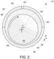
- FIG. 2 the figure is a front view illustrating an embodiment of the journal bearing system 10.
- the illustrated embodiment includes two bearings 34 and 36 surrounding a journal or shaft 38.
- Oil or lubricant 40 may be disposed between the bearings 34, 36 and the journal 38.
- the oil 40 may enter and or exit the bearing system 10 via one or more oil ports 42.
- the journal bearings 34, 36 may support journals 38 such as crankshafts, camshafts, piston shafts, flywheel shafts, and so on, as the journals 38 rotate about certain axes, such as axis 44, 46.
- Axis 44 is representative of an axis concentric with the center of a circle formed by the bearings or shells 34, 36, while axis 46 is representative of a displacement axis caused by the displacement of the journal 38 during rotative operations, creating an eccentricity e.
- the bearings 34, 36 may be disposed in a variety of housings (not shown) depending on where in the engine 11 the bearings 34, 36 may be located.
- journal 38 As the journal 38 rotates inside of the bearings 34, 36, a pressurized lubricant film of the oil 48 may be generated by the journal 38 rotation, providing for a hydrodynamic journal bearing system 10.
- the journal 38 may experience certain wear and tear.
- the journal 38 may contact the bearings 34, 36 at inner surfaces 48, 50 which may cause wear and tear on the bearings 34, 36. Outside surfaces 52, 54, may not experience much, if any wear and tear.
- Bearings 34, 36 may eventually need replacing.
- Bearings 34, 36 may accumulate wear and tear differently based on operating conditions. For example, engine 11 start-stops may result in higher levels of bearing 34, 36 wear when compared to the engine 11 operating at steady state (e.g., base load) conditions.
- the bearings 34, 36 may be replaced at a certain number of operating hours for the engine 11 irrespective of the actual wear on the bearings 34, 36.
- the techniques described herein may provide for predictive actual wear on the bearings 34, 36 and/or the journal 38. Accordingly, the lifecycle and maintenance schedule for the bearings 34, 36and the journal 38 may be improved.
- the predicted actual wear and tear on the bearings 34, 36 and/or the journal 38 may be within +/- 7% of observed actual wear and tear, thus providing for improved derivation of remaining life, and thus more efficient maintenance schedules.
- FIG. 3 is a flowchart illustrating an embodiment of a process 60 suitable for deriving a mixed lubrication model.
- the process 60 may be implemented as computer code or instructions stored in the memory 30 and executable via the processor 28. Additionally or alternatively, the process 60 may be implemented in hardware, such as in a custom chip, FPGA chip, and so on.
- tribology theory may be used to derive (block 62) a pressure p and a film thickness h.
- Reynold's equation and elastic deformation equations may be used to derive p (x,y) and h (x,y) along x and y axis where the x axis may include a circumference for the journal 38 and the y axis may include a length for the journal 38.
- the process 60 may then derive (decision 64) if the film thickness h divided by a root mean square roughness (Rq) for the journal surface is greater than a constant, such as 4. If the film thickness h divided by Rq is greater than 4 (decision 64), then the process 60 may determine (block 66) that the journal 38 is operating under a lubricated regime and thus, that the pressure p is equivalent to a fluid pressure p f .
- the process 60 may derive (block 68) an asperity contact pressure p c .
- an asperity contact pressure p c For example, the Greenwood-Tripp asperity contact model may be used to derive p c .
- the constant of 4 is one example. Constants larger than 4 may provide for situations where asperity contact is more prevalent, and constants smaller than 4 may provide for situations having less asperity contact.
- the Greenwood-Trip asperity contact model gives a general theory of contact between two rough plane surfaces. The model shows that the load and the area of contact remain almost proportional, independently of the detailed mechanical and geometrical properties of the asperities. Further, a single-rough-surface Greenwood-Trip asperity contact model can always be found which will predict the same laws as a given two-rough-surface model.
- the process 60 may derive (block 78) that a mixed lubrication model is derivable. Otherwise, the process 60 may change eccentricity e (block 80) and loop to block 62. The process 60 may then derive (block 78) a mixed lubrication model 82.
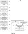
- FIG. 4 is a flowchart illustrating an embodiment of a process 90 suitable for predicting wear and tear for the journal bearing system 10.
- the process 90 may be implemented as computer code or instructions stored in the memory 30 and executable via the processor 28. Additionally or alternatively, the process 90 may be implemented in hardware, such as in a custom chip, FPGA chip, and so on.
- the process 90 may first create (block 92) one or more models 94, such as physics-based models of the journal bearing system 10 and/or power production system 8.
- the physics-based models may simulate operations of the journal bearing system 10 and/or power production system 8.
- one of the models 94 may include model 82 described above.
- oil 40 properties such as viscosity, temperature, isothermal compressibility, interfacial tension, and the like, may be modeled.
- the power production system 8 models may include models detailing speed, torque, power production, temperature of various components, pressures, flow rates, and so on, of the various components.
- the models 94 may additionally take into account material make up for the bearings 34, 36 and journal 38, as well as certain geometries and/or architectures of the bearing system 10, such as eccentricity e, oil clearance, crush height, journal diameter, journal shape (e.g., circular, concave, convex, tapered), and so on.
- the journal bearing system models 94 may take as input start-stop (SS) operating hours and steady-state (OH) operating hours to increase accuracy. That is, rather than simply input the number of operating hours, the models 94 may receive as input SS hours of operation and OH hours of operation, and then derive wear.
- physics-based models may model degradation due to heat, abrasion, abutment of journal 34 against bearings 34, 36, oil viscosity, pressures, flow rates, temperatures, speeds, and so on.
- the degradation may thus be indicative of wear. That is, successive degradation is representative of cumulative wear. Accordingly, wear and remaining life may be determined for the bearings 34, 36, the journal 38, and/or the oil 40.
- the process 90 may improve accuracy by using field data.
- the field data may provide for the derivation of certain test procedures that more accurately may derive one or more transfer functions as well as calibration coefficients, and described in more detail below.
- the process 90 may communicate the field data (block 96), for example via wired or wireless techniques.
- the field data may include real-time data from the sensors 23 and/or instrumented journal bearing system 10 embodiments, as well as data from logs stored in the ECU 25 and/or other systems.
- the data may include temperatures, pressures, fluid flows, clearances, operating hours, and/or start-stops for the components of the system 8.
- Table 1 above is illustrative of an example wear protocol (second column) suitable for modeling a J624 engine bearing field conditions (first column).
- the J624 engine bearing has a diameter of 183 millimeters (mm), while the test bearing used in the wear protocol has a diameter of 48 millimeters (mm).
- the wear protocol for larger sized bearings may test a smaller bearing and provide results that would be indicative of testing the larger sized bearing.
- the wear protocol for example, may operate the smaller test bearing at faster journal speeds, and/or accelerations to provide for wear similar to the larger sized bearing.
- a generic wear protocol third column that may be customized to a variety of bearing types and sizes.
- the wear protocol may then be executed (block 100) via the test rig 32, for example, to observe or obtain SS and/or OH wear at various operating times.
- the test bearing may be operated at start-stop conditions and then tested to obtain SS wear.
- the test bearing may be operated at steady state conditions and then tested to obtain OH wear.
- the test bearing may be operated at both start-stop conditions and steady state conditions and then tested to obtain a combination of SS and OH wear.
- the test rig 32 may apply certain speeds and/or loads for a desired time.
- the test rig 32 may simulate start-stop conditions by applying a journal speed profile 152, a bearing unit profile 154, and an inlet oil temperature profile 156.
- the profiles 152, 154, 156 may be executed by the test rig 32 at a desired time range shown in x-axis 156.
- Y-axis 158 shows values for journal linear speed in m/s and bearing unit load in MPa.
- Y-axis 160 shows temperature in C°.
- Steady state conditions may be modeled by operating the test rig 32, for example, at constant speed, such as the journal speed, surface speed, or combination thereof. Likewise, constant bearing loads may be tested during steady state testing. Test steady state operations, like field steady state operations, may be measured in minutes and/or hours.
- the process 90 may derive (block 102) one or more transfer functions 104.
- ⁇ f 2 OH where ⁇ is representative of wear and f 2 is a function that takes as input the number of steady state operating hours to arrive at the wear ⁇ .
- the number of start-stops may be derived based on knowing the number of steady state operating hours and/or based on a known wear, and vice versa.
- the transfer function 104 shown above enables for the calculation of wear due to the number of start-stops, due to the number of steady state operating hours, or a combination thereof.
- the process 90 may calibrate (block 106) certain field wear coefficients and apply the calibrated coefficients to the models(s) 94 and/or transfer function(s) 104 to derive and calibrate (block 108) calibrated models 110 and/or transfer functions 112, as further detailed below.
- log data including SS and/or OH may be for the engine 11 may be retrieved, and/or similar data provided real-time, and used to predict (block 114) a more accurate wear for components of the journal bearing system 10 (e.g., bearings 34, 36, journal 38, oil 40) via the calibrated models 110 and/or transfer functions 112.
- the ECU 25 may solve for wear ⁇ via the calibrated models 110 and transfer functions 112 by using SS and/or OH data as inputs.
- the process 90 may then provide (block 116) certain actionable item, such as alarms/alerts, improved maintenance schedules, and the like.
- the predictive wear ⁇ exceeds a threshold, and/or a growth rate, alarms/alerts may be provided.
- maintenance schedules may be based on the predictive wear ⁇ as opposed to number of operating hours for the engine 11. In this manner, life and operations for the engine system 8 may be improved.
- FIG. 6 illustrates example graphs 170, 172, showing calibration of parameters K based on experimental and/or field data 174, 176, respectively.
- the models 94 may include calibration parameters K suitable for calibration certain models.
- the calibration parameters K (e.g., K 1 ) may be calibrated by applying certain techniques, such as statistical techniques (e.g., linear regression, non-linear regression, data mining [e.g., k-means clustering and the like]), onto the data 174, 176.
- graph 170 shows calibration parameters 178, 180, 182, and 184 that may be used, but in the example, calibration parameter 180 appears to fit the data 174 with improved accuracy. Accordingly, the calibration parameter 180 may be used to calibrate models 94, thus better "fitting" the experimental and/or field use data for start-stop wear.
- graph 172 shows calibration parameters 186, 188, and 190 that may be used, but in the example, calibration parameter 190 appears to fit the data 176 with improved accuracy. Accordingly, the calibration parameter 190 may be used to calibrate models 94, thus better "fitting" the experimental and/or field use data for steady state wear. The calibrations may then be applied, for example, to the models 94 to derive the calibrated models 110. By calibrating the models, the techniques described herein may increase predictive accuracy.
- FIG. 7 the figure illustrates an embodiment of a calibrated graph 250 that may be derived via the models 110 and applied to find a wear based on a number of start-stops, steady state operating hours, or a combination thereof.
- the graph 250 includes a wear (in microns) axis 252, a number of start-stop axis 254, and an operating hours axis 256.
- a process such as the process 90, may apply the graph 250 as a "lookup" graph or table suitable for more quickly deriving wear based on the number of start-stops, steady state operating hours, or the combination thereof.
- the graph 250 may be created by combining the number of start stops with steady state operating hours as describe above, and then by calibrating the results, for example, via field wear data as described earlier with respect to calibration parameters K.
Landscapes
- Engineering & Computer Science (AREA)
- Physics & Mathematics (AREA)
- General Physics & Mathematics (AREA)
- Data Mining & Analysis (AREA)
- Mathematical Optimization (AREA)
- Pure & Applied Mathematics (AREA)
- Theoretical Computer Science (AREA)
- General Engineering & Computer Science (AREA)
- Mathematical Physics (AREA)
- Mathematical Analysis (AREA)
- Computational Mathematics (AREA)
- Operations Research (AREA)
- Probability & Statistics with Applications (AREA)
- Life Sciences & Earth Sciences (AREA)
- Algebra (AREA)
- Bioinformatics & Cheminformatics (AREA)
- Databases & Information Systems (AREA)
- Software Systems (AREA)
- Evolutionary Biology (AREA)
- Bioinformatics & Computational Biology (AREA)
- Automation & Control Theory (AREA)
- Sliding-Contact Bearings (AREA)
Claims (14)
- Verfahren zur Bestimmung des Verschleißes eines Gleitlagersystems (10) eines Motors, umfassend:- Ausführen eines Verschleißprotokolls, um einen Start-Stopp-Verschleiß (SS), einen Verschleiß im stationären Betrieb (OH) oder eine Kombination davon eines Testgleitlagersystems (10) auf einem Prüfstand (32) abzuleiten;- Ableiten einer Übertragungsfunktion, die zur Bestimmung eines Gesamtverschleißes für das Testgleitlagersystem (10) auf der Grundlage des SS-Verschleißes, des OH-Verschleißes oder einer Kombination davon geeignet ist;- Beobachten des Betriebs des Motors (11) über einen oder mehrere Sensoren (23), um eine Anzahl von Start-Stopps, Betriebsstunden im stationären Zustand oder eine Kombination davon abzuleiten;- Bestimmen des Verschleißes des Gleitlagersystems (10) anhand eines bestimmten Test-Gleitlagersystems (10) auf der Grundlage der Anwendung der Übertragungsfunktion auf die Anzahl der Start-Stopps, die stationären Betriebsstunden oder eine Kombination davon; und- Ausführen einer oder mehrerer umsetzbarer Maßnahmen an dem Motor (11) auf der Grundlage des ermittelten Verschleißes des Gleitlagersystems (10)wobei die Bestimmung des Verschleißes des Gleitlagersystems (10) darüber hinaus auf einem physikalischen Modell des Gleitlagersystems (10) basiert.
- Das Verfahren nach Anspruch 1, wobei die Übertragungsfunktion eine


- Verfahren nach Anspruch 1, wobei das physikalische Modell ein feldkalibriertes Modell umfasst, die Übertragungsfunktion eine feldkalibrierte Übertragungsfunktion umfasst oder eine Kombination davon.
- Verfahren nach Anspruch 3, umfassend das Ableiten des feldkalibrierten Modells, der feldkalibrierten Übertragungsfunktion oder einer Kombination davon über Daten, die von den Sensoren (23) während Feldbeobachtungen des Betriebs des Motors (11) empfangen werden, um einen oder mehrere Kalibrierungsparameter K abzuleiten.
- Verfahren nach Anspruch 4, wobei das Ableiten des einen oder der mehreren Kalibrierungsparameter K das Anwenden einer linearen Regression, einer nichtlinearen Regression, eines Data Mining oder einer Kombination davon auf die über die Sensoren (23) empfangenen Daten umfasst.
- Verfahren nach Anspruch 1, wobei das physikalische Modell des Gleitlagersystems (10) ein Mischschmiermodell umfasst, das sowohl einen geschmierten Bereich als auch einen Rauheitskontaktbereich umfasst.
- Verfahren nach Anspruch 6, wobei der geschmierte Zustand einen pf = p umfasst, wobei pf dem Fluiddruck entspricht und p dem Druck entspricht, und wobei der Rauheitskontaktbereich einen pc umfasst, wobei pc einen Rauheitskontaktdruck umfasst.
- Verfahren nach Anspruch 7, umfassend das Ableiten des Rauheitskontaktdrucks über ein Greenwood-Tripp-Rauheitskontaktmodell.
- Verfahren nach Anspruch 1, wobei das Bestimmen des Verschleißes des bestimmten Gleitlagersystems (10) das Bestimmen eines Gleitlager-Verschleißes, eines Lager-Verschleißes, eines Öl-Verschleißes oder einer Kombination davon umfasst.
- System zur Bestimmung des Verschleißes eines Gleitlagersystems (10) eines Motors, umfassend:- eine elektronische Steuereinheit (ECU) (25), die einen Speicher (30) oder eine Speichervorrichtung, die eine oder mehrere prozessorausführbare Routinen speichert, oder beides umfasst; und- einen oder mehrere Prozessoren (28), die so konfiguriert sind, dass sie die eine oder mehreren ausführbaren Routinen ausführen, die bei ihrer Ausführung Handlungen ausführen, die Folgendes umfassen:- Steuerung des Betriebs des Motors (11);- Beobachten des Betriebs des Motors (11) über einen oder mehrere Sensoren (23), um eine Anzahl von Start-Stopps, Betriebsstunden im stationären Zustand oder eine Kombination davon abzuleiten;- Bestimmen des Verschleißes des Gleitlagersystems (10) anhand eines bestimmten Test-Gleitlagersystems (10) auf der Grundlage der Anwendung einer Übertragungsfunktion auf die Anzahl der Start-Stopps, die Betriebsstunden im stationären Zustand oder auf die Kombination davon; und- Ausführen einer oder mehrerer umsetzbarer Maßnahmen an der Maschine (11) auf der Grundlage des ermittelten Verschleißes des Gleitlagersystems (10)wobei die Bestimmung des Verschleißes des Gleitlagersystems (10) außerdem auf einem physikalischen Modell des Gleitlagersystems (10) basiert.
- Das System nach Anspruch 10, wobei die Übertragungsfunktion eine


- System nach Anspruch 10, wobei das physikalische Modell ein feldkalibriertes Modell umfasst, die Übertragungsfunktion eine feldkalibrierte Übertragungsfunktion oder eine Kombination davon umfasst.
- Das System nach Anspruch 10, wobei das physikalische Modell des Gleitlagersystems (10) ein Mischschmiermodell umfasst, das sowohl einen geschmierten Bereich als auch einen Rauheitskontaktbereich umfasst.
- Das System nach Anspruch 10, wobei das Ausführen der ausführbaren Elemente auf dem Motor (11) das Auslösen eines Alarms, das Abschalten des Motors (11), das Verringern der Drehzahl des Motors (11), das Hinzufügen eines Datenbankprotokolleintrags oder eine Kombination davon umfasst.
Applications Claiming Priority (2)
| Application Number | Priority Date | Filing Date | Title |
|---|---|---|---|
| IN6773CH2015 | 2015-12-18 | ||
| PCT/US2016/064134 WO2017105839A1 (en) | 2015-12-18 | 2016-11-30 | System and method for improved journal bearing operations |
Publications (2)
| Publication Number | Publication Date |
|---|---|
| EP3391010A1 EP3391010A1 (de) | 2018-10-24 |
| EP3391010B1 true EP3391010B1 (de) | 2025-07-09 |
Family
ID=57590846
Family Applications (1)
| Application Number | Title | Priority Date | Filing Date |
|---|---|---|---|
| EP16816510.8A Active EP3391010B1 (de) | 2015-12-18 | 2016-11-30 | System und verfahren für verbesserte gleitlageroperationen |
Country Status (3)
| Country | Link |
|---|---|
| US (1) | US10876927B2 (de) |
| EP (1) | EP3391010B1 (de) |
| WO (1) | WO2017105839A1 (de) |
Families Citing this family (4)
| Publication number | Priority date | Publication date | Assignee | Title |
|---|---|---|---|---|
| DE102017223418B4 (de) * | 2017-12-20 | 2023-05-25 | Zf Friedrichshafen Ag | Modellbasiertes Verfahren und System zur Zustandsüberwachung eines Gleitlagers, insbesondere für Windkraftanlagen |
| CN109696309B (zh) * | 2018-12-27 | 2021-05-14 | 江铃控股有限公司 | 汽车发动机自动启停耐久试验方法 |
| CN113669375B (zh) * | 2021-09-02 | 2023-05-16 | 武汉联影医疗科技有限公司 | 动压滑动轴承的使用情况确定方法、系统、装置 |
| CN121881548A (zh) * | 2026-03-18 | 2026-04-17 | 潍柴动力股份有限公司 | 轴承间隙优化方法、装置、电子设备、存储介质 |
Family Cites Families (6)
| Publication number | Priority date | Publication date | Assignee | Title |
|---|---|---|---|---|
| JP4504065B2 (ja) | 2004-03-31 | 2010-07-14 | 中国電力株式会社 | 転がり軸受の余寿命診断方法 |
| EP1790844A1 (de) * | 2005-11-25 | 2007-05-30 | Delphi Technologies, Inc. | Verfahren zur Identifizierung vom abnormalen Verhalten eines Dynamischen Systems |
| DE102007036271A1 (de) * | 2007-07-31 | 2009-02-05 | Baumer Hübner GmbH | Drehgeber mit Überwachung des Lagerverschleißes sowie Verfahren hierzu |
| WO2009138106A1 (en) * | 2008-05-14 | 2009-11-19 | Ab Skf | Prediction of relubrication interval |
| CN102589885B (zh) | 2012-03-09 | 2014-04-09 | 北京航空航天大学 | 一种箔片动压径向气体轴承磨损寿命的预测方法 |
| US20150082871A1 (en) * | 2013-09-20 | 2015-03-26 | Cummins Inc. | Onboard diagnostic of engine oil quality by using a transfer function with a plurality of fluid property sensors |
-
2016
- 2016-11-30 WO PCT/US2016/064134 patent/WO2017105839A1/en not_active Ceased
- 2016-11-30 US US16/063,386 patent/US10876927B2/en active Active
- 2016-11-30 EP EP16816510.8A patent/EP3391010B1/de active Active
Also Published As
| Publication number | Publication date |
|---|---|
| WO2017105839A1 (en) | 2017-06-22 |
| EP3391010A1 (de) | 2018-10-24 |
| US20180372585A1 (en) | 2018-12-27 |
| US10876927B2 (en) | 2020-12-29 |
Similar Documents
| Publication | Publication Date | Title |
|---|---|---|
| Ryk et al. | Testing piston rings with partial laser surface texturing for friction reduction | |
| Wannatong et al. | Simulation algorithm for piston ring dynamics | |
| US10876927B2 (en) | System and method for improved journal bearing operations | |
| Qiu et al. | Investigation of tribological behaviors of annular rings with spiral groove | |
| Gertzos et al. | Wear identification in rotor-bearing systems by measurements of dynamic bearing characteristics | |
| Moon et al. | Evaluation of lubrication performance of crank pin bearing in a marine diesel engine | |
| Regis et al. | Physic-based vs data-based digital twins for bush bearing wear diagnostic | |
| Mufti et al. | Effect of engine operating conditions and lubricant rheology on the distribution of losses in an internal combustion engine | |
| Cavacece et al. | Roller bearing under high loaded oscillations: Life evolution and accommodation mechanisms | |
| Mikic et al. | Reliability analysis of ball bearing on the crankshaft of piston compressors | |
| Yin et al. | Temperature evolution prediction of engine big-end bearing by tribo-dynamics modeling and wireless measurement verification | |
| ul Islam et al. | Experimental and theoretical evaluation of friction in roller follower valve train | |
| Zhu et al. | Thermoelectric effect of wear of alloy bearing | |
| Piao et al. | Numerical investigation of the effects of axial cylinder bore profiles on piston ring radial dynamics | |
| Liu et al. | Experimental investigation of leakage flow measurement and surface morphology in small-scale liquid mechanical seals | |
| Mishra | Thermal modeling of thin lubricant film within piston compression ring and rough cyliner liner conjuction | |
| Kobylskiy et al. | Predicting the service life of cylinder-piston seals of reciprocating compressors | |
| Yin et al. | Wear failure analysis based on a new tribo-dynamic-wear coupling model for big-end bearings and heavy-duty engine experiments | |
| Law et al. | A new floating-liner test rig design to investigate factors influencing piston-liner friction | |
| Moussa | Thermography-assisted bearing condition monitoring | |
| Korn | Slide-to-roll ratio in automotive valve train cam and oscillating roller follower | |
| Wolff | Influence of engine load on piston ring pack operation of a marine two-stroke engine | |
| Meng et al. | A study of the influences of particles in the gas flow passage of a piston ring pack on the tribological performances of the piston ring | |
| Biswas et al. | Monitoring of bearing wear in a marine engine by change of piston position—Effect of wear and inertia | |
| Xu | Predictive modeling of piston assembly lubrication in reciprocating internal combustion engines |
Legal Events
| Date | Code | Title | Description |
|---|---|---|---|
| STAA | Information on the status of an ep patent application or granted ep patent |
Free format text: STATUS: UNKNOWN |
|
| STAA | Information on the status of an ep patent application or granted ep patent |
Free format text: STATUS: THE INTERNATIONAL PUBLICATION HAS BEEN MADE |
|
| PUAI | Public reference made under article 153(3) epc to a published international application that has entered the european phase |
Free format text: ORIGINAL CODE: 0009012 |
|
| STAA | Information on the status of an ep patent application or granted ep patent |
Free format text: STATUS: REQUEST FOR EXAMINATION WAS MADE |
|
| 17P | Request for examination filed |
Effective date: 20180718 |
|
| AK | Designated contracting states |
Kind code of ref document: A1 Designated state(s): AL AT BE BG CH CY CZ DE DK EE ES FI FR GB GR HR HU IE IS IT LI LT LU LV MC MK MT NL NO PL PT RO RS SE SI SK SM TR |
|
| AX | Request for extension of the european patent |
Extension state: BA ME |
|
| DAV | Request for validation of the european patent (deleted) | ||
| DAX | Request for extension of the european patent (deleted) | ||
| STAA | Information on the status of an ep patent application or granted ep patent |
Free format text: STATUS: EXAMINATION IS IN PROGRESS |
|
| 17Q | First examination report despatched |
Effective date: 20190614 |
|
| RAP1 | Party data changed (applicant data changed or rights of an application transferred) |
Owner name: AI ALPINE US BIDCO INC. |
|
| P01 | Opt-out of the competence of the unified patent court (upc) registered |
Effective date: 20230602 |
|
| GRAP | Despatch of communication of intention to grant a patent |
Free format text: ORIGINAL CODE: EPIDOSNIGR1 |
|
| STAA | Information on the status of an ep patent application or granted ep patent |
Free format text: STATUS: GRANT OF PATENT IS INTENDED |
|
| INTG | Intention to grant announced |
Effective date: 20250310 |
|
| GRAS | Grant fee paid |
Free format text: ORIGINAL CODE: EPIDOSNIGR3 |
|
| GRAA | (expected) grant |
Free format text: ORIGINAL CODE: 0009210 |
|
| STAA | Information on the status of an ep patent application or granted ep patent |
Free format text: STATUS: THE PATENT HAS BEEN GRANTED |
|
| AK | Designated contracting states |
Kind code of ref document: B1 Designated state(s): AL AT BE BG CH CY CZ DE DK EE ES FI FR GB GR HR HU IE IS IT LI LT LU LV MC MK MT NL NO PL PT RO RS SE SI SK SM TR |
|
| REG | Reference to a national code |
Ref country code: GB Ref legal event code: FG4D |
|
| REG | Reference to a national code |
Ref country code: CH Ref legal event code: EP |
|
| REG | Reference to a national code |
Ref country code: IE Ref legal event code: FG4D |
|
| REG | Reference to a national code |
Ref country code: DE Ref legal event code: R096 Ref document number: 602016092856 Country of ref document: DE |
|
| REG | Reference to a national code |
Ref country code: NL Ref legal event code: MP Effective date: 20250709 |
|
| PG25 | Lapsed in a contracting state [announced via postgrant information from national office to epo] |
Ref country code: PT Free format text: LAPSE BECAUSE OF FAILURE TO SUBMIT A TRANSLATION OF THE DESCRIPTION OR TO PAY THE FEE WITHIN THE PRESCRIBED TIME-LIMIT Effective date: 20251110 |
|
| PG25 | Lapsed in a contracting state [announced via postgrant information from national office to epo] |
Ref country code: NL Free format text: LAPSE BECAUSE OF FAILURE TO SUBMIT A TRANSLATION OF THE DESCRIPTION OR TO PAY THE FEE WITHIN THE PRESCRIBED TIME-LIMIT Effective date: 20250709 |
|
| REG | Reference to a national code |
Ref country code: AT Ref legal event code: MK05 Ref document number: 1812200 Country of ref document: AT Kind code of ref document: T Effective date: 20250709 |
|
| PG25 | Lapsed in a contracting state [announced via postgrant information from national office to epo] |
Ref country code: IS Free format text: LAPSE BECAUSE OF FAILURE TO SUBMIT A TRANSLATION OF THE DESCRIPTION OR TO PAY THE FEE WITHIN THE PRESCRIBED TIME-LIMIT Effective date: 20251109 |
|
| PGFP | Annual fee paid to national office [announced via postgrant information from national office to epo] |
Ref country code: DE Payment date: 20251022 Year of fee payment: 10 |
|
| PG25 | Lapsed in a contracting state [announced via postgrant information from national office to epo] |
Ref country code: NO Free format text: LAPSE BECAUSE OF FAILURE TO SUBMIT A TRANSLATION OF THE DESCRIPTION OR TO PAY THE FEE WITHIN THE PRESCRIBED TIME-LIMIT Effective date: 20251009 |
|
| REG | Reference to a national code |
Ref country code: LT Ref legal event code: MG9D |
|
| PG25 | Lapsed in a contracting state [announced via postgrant information from national office to epo] |
Ref country code: AT Free format text: LAPSE BECAUSE OF FAILURE TO SUBMIT A TRANSLATION OF THE DESCRIPTION OR TO PAY THE FEE WITHIN THE PRESCRIBED TIME-LIMIT Effective date: 20250709 |
|
| PG25 | Lapsed in a contracting state [announced via postgrant information from national office to epo] |
Ref country code: FI Free format text: LAPSE BECAUSE OF FAILURE TO SUBMIT A TRANSLATION OF THE DESCRIPTION OR TO PAY THE FEE WITHIN THE PRESCRIBED TIME-LIMIT Effective date: 20250709 |
|
| PG25 | Lapsed in a contracting state [announced via postgrant information from national office to epo] |
Ref country code: HR Free format text: LAPSE BECAUSE OF FAILURE TO SUBMIT A TRANSLATION OF THE DESCRIPTION OR TO PAY THE FEE WITHIN THE PRESCRIBED TIME-LIMIT Effective date: 20250709 |
|
| PG25 | Lapsed in a contracting state [announced via postgrant information from national office to epo] |
Ref country code: GR Free format text: LAPSE BECAUSE OF FAILURE TO SUBMIT A TRANSLATION OF THE DESCRIPTION OR TO PAY THE FEE WITHIN THE PRESCRIBED TIME-LIMIT Effective date: 20251010 |
|
| PG25 | Lapsed in a contracting state [announced via postgrant information from national office to epo] |
Ref country code: SE Free format text: LAPSE BECAUSE OF FAILURE TO SUBMIT A TRANSLATION OF THE DESCRIPTION OR TO PAY THE FEE WITHIN THE PRESCRIBED TIME-LIMIT Effective date: 20250709 |
|
| PG25 | Lapsed in a contracting state [announced via postgrant information from national office to epo] |
Ref country code: LV Free format text: LAPSE BECAUSE OF FAILURE TO SUBMIT A TRANSLATION OF THE DESCRIPTION OR TO PAY THE FEE WITHIN THE PRESCRIBED TIME-LIMIT Effective date: 20250709 |
|
| PG25 | Lapsed in a contracting state [announced via postgrant information from national office to epo] |
Ref country code: PL Free format text: LAPSE BECAUSE OF FAILURE TO SUBMIT A TRANSLATION OF THE DESCRIPTION OR TO PAY THE FEE WITHIN THE PRESCRIBED TIME-LIMIT Effective date: 20250709 Ref country code: BG Free format text: LAPSE BECAUSE OF FAILURE TO SUBMIT A TRANSLATION OF THE DESCRIPTION OR TO PAY THE FEE WITHIN THE PRESCRIBED TIME-LIMIT Effective date: 20250709 |
|
| PG25 | Lapsed in a contracting state [announced via postgrant information from national office to epo] |
Ref country code: RS Free format text: LAPSE BECAUSE OF FAILURE TO SUBMIT A TRANSLATION OF THE DESCRIPTION OR TO PAY THE FEE WITHIN THE PRESCRIBED TIME-LIMIT Effective date: 20251009 |
|
| PG25 | Lapsed in a contracting state [announced via postgrant information from national office to epo] |
Ref country code: ES Free format text: LAPSE BECAUSE OF FAILURE TO SUBMIT A TRANSLATION OF THE DESCRIPTION OR TO PAY THE FEE WITHIN THE PRESCRIBED TIME-LIMIT Effective date: 20250709 |
|
| PG25 | Lapsed in a contracting state [announced via postgrant information from national office to epo] |
Ref country code: RO Free format text: LAPSE BECAUSE OF FAILURE TO SUBMIT A TRANSLATION OF THE DESCRIPTION OR TO PAY THE FEE WITHIN THE PRESCRIBED TIME-LIMIT Effective date: 20250709 |
|
| PG25 | Lapsed in a contracting state [announced via postgrant information from national office to epo] |
Ref country code: SM Free format text: LAPSE BECAUSE OF FAILURE TO SUBMIT A TRANSLATION OF THE DESCRIPTION OR TO PAY THE FEE WITHIN THE PRESCRIBED TIME-LIMIT Effective date: 20250709 |
|
| PG25 | Lapsed in a contracting state [announced via postgrant information from national office to epo] |
Ref country code: DK Free format text: LAPSE BECAUSE OF FAILURE TO SUBMIT A TRANSLATION OF THE DESCRIPTION OR TO PAY THE FEE WITHIN THE PRESCRIBED TIME-LIMIT Effective date: 20250709 |
|
| PG25 | Lapsed in a contracting state [announced via postgrant information from national office to epo] |
Ref country code: IT Free format text: LAPSE BECAUSE OF FAILURE TO SUBMIT A TRANSLATION OF THE DESCRIPTION OR TO PAY THE FEE WITHIN THE PRESCRIBED TIME-LIMIT Effective date: 20250709 |
|
| PG25 | Lapsed in a contracting state [announced via postgrant information from national office to epo] |
Ref country code: CZ Free format text: LAPSE BECAUSE OF FAILURE TO SUBMIT A TRANSLATION OF THE DESCRIPTION OR TO PAY THE FEE WITHIN THE PRESCRIBED TIME-LIMIT Effective date: 20250709 |
|
| PG25 | Lapsed in a contracting state [announced via postgrant information from national office to epo] |
Ref country code: SK Free format text: LAPSE BECAUSE OF FAILURE TO SUBMIT A TRANSLATION OF THE DESCRIPTION OR TO PAY THE FEE WITHIN THE PRESCRIBED TIME-LIMIT Effective date: 20250709 Ref country code: EE Free format text: LAPSE BECAUSE OF FAILURE TO SUBMIT A TRANSLATION OF THE DESCRIPTION OR TO PAY THE FEE WITHIN THE PRESCRIBED TIME-LIMIT Effective date: 20250709 |
|
| PLBE | No opposition filed within time limit |
Free format text: ORIGINAL CODE: 0009261 |
|
| STAA | Information on the status of an ep patent application or granted ep patent |
Free format text: STATUS: NO OPPOSITION FILED WITHIN TIME LIMIT |