EP3390812B2 - Teilerplattenanordnung für gezahnte windturbinenschaufel - Google Patents
Teilerplattenanordnung für gezahnte windturbinenschaufel Download PDFInfo
- Publication number
- EP3390812B2 EP3390812B2 EP16816661.9A EP16816661A EP3390812B2 EP 3390812 B2 EP3390812 B2 EP 3390812B2 EP 16816661 A EP16816661 A EP 16816661A EP 3390812 B2 EP3390812 B2 EP 3390812B2
- Authority
- EP
- European Patent Office
- Prior art keywords
- serrations
- wind turbine
- turbine blade
- splitter
- splitter plate
- Prior art date
- Legal status (The legal status is an assumption and is not a legal conclusion. Google has not performed a legal analysis and makes no representation as to the accuracy of the status listed.)
- Active
Links
Images


Classifications
-
- F—MECHANICAL ENGINEERING; LIGHTING; HEATING; WEAPONS; BLASTING
- F03—MACHINES OR ENGINES FOR LIQUIDS; WIND, SPRING, OR WEIGHT MOTORS; PRODUCING MECHANICAL POWER OR A REACTIVE PROPULSIVE THRUST, NOT OTHERWISE PROVIDED FOR
- F03D—WIND MOTORS
- F03D1/00—Wind motors with rotation axis substantially parallel to the air flow entering the rotor
- F03D1/06—Rotors
- F03D1/065—Rotors characterised by their construction elements
- F03D1/0675—Rotors characterised by their construction elements of the blades
-
- F—MECHANICAL ENGINEERING; LIGHTING; HEATING; WEAPONS; BLASTING
- F03—MACHINES OR ENGINES FOR LIQUIDS; WIND, SPRING, OR WEIGHT MOTORS; PRODUCING MECHANICAL POWER OR A REACTIVE PROPULSIVE THRUST, NOT OTHERWISE PROVIDED FOR
- F03D—WIND MOTORS
- F03D1/00—Wind motors with rotation axis substantially parallel to the air flow entering the rotor
- F03D1/06—Rotors
- F03D1/0608—Rotors characterised by their aerodynamic shape
- F03D1/0633—Rotors characterised by their aerodynamic shape of the blades
- F03D1/0641—Rotors characterised by their aerodynamic shape of the blades of the section profile of the blades, i.e. aerofoil profile
-
- F—MECHANICAL ENGINEERING; LIGHTING; HEATING; WEAPONS; BLASTING
- F05—INDEXING SCHEMES RELATING TO ENGINES OR PUMPS IN VARIOUS SUBCLASSES OF CLASSES F01-F04
- F05B—INDEXING SCHEME RELATING TO WIND, SPRING, WEIGHT, INERTIA OR LIKE MOTORS, TO MACHINES OR ENGINES FOR LIQUIDS COVERED BY SUBCLASSES F03B, F03D AND F03G
- F05B2240/00—Components
- F05B2240/20—Rotors
- F05B2240/30—Characteristics of rotor blades, i.e. of any element transforming dynamic fluid energy to or from rotational energy and being attached to a rotor
-
- F—MECHANICAL ENGINEERING; LIGHTING; HEATING; WEAPONS; BLASTING
- F05—INDEXING SCHEMES RELATING TO ENGINES OR PUMPS IN VARIOUS SUBCLASSES OF CLASSES F01-F04
- F05B—INDEXING SCHEME RELATING TO WIND, SPRING, WEIGHT, INERTIA OR LIKE MOTORS, TO MACHINES OR ENGINES FOR LIQUIDS COVERED BY SUBCLASSES F03B, F03D AND F03G
- F05B2250/00—Geometry
- F05B2250/10—Geometry two-dimensional
- F05B2250/18—Geometry two-dimensional patterned
- F05B2250/183—Geometry two-dimensional patterned zigzag
-
- F—MECHANICAL ENGINEERING; LIGHTING; HEATING; WEAPONS; BLASTING
- F05—INDEXING SCHEMES RELATING TO ENGINES OR PUMPS IN VARIOUS SUBCLASSES OF CLASSES F01-F04
- F05B—INDEXING SCHEME RELATING TO WIND, SPRING, WEIGHT, INERTIA OR LIKE MOTORS, TO MACHINES OR ENGINES FOR LIQUIDS COVERED BY SUBCLASSES F03B, F03D AND F03G
- F05B2260/00—Function
- F05B2260/96—Preventing, counteracting or reducing vibration or noise
-
- F—MECHANICAL ENGINEERING; LIGHTING; HEATING; WEAPONS; BLASTING
- F05—INDEXING SCHEMES RELATING TO ENGINES OR PUMPS IN VARIOUS SUBCLASSES OF CLASSES F01-F04
- F05B—INDEXING SCHEME RELATING TO WIND, SPRING, WEIGHT, INERTIA OR LIKE MOTORS, TO MACHINES OR ENGINES FOR LIQUIDS COVERED BY SUBCLASSES F03B, F03D AND F03G
- F05B2280/00—Materials; Properties thereof
- F05B2280/60—Properties or characteristics given to material by treatment or manufacturing
- F05B2280/6003—Composites; e.g. fibre-reinforced
-
- Y—GENERAL TAGGING OF NEW TECHNOLOGICAL DEVELOPMENTS; GENERAL TAGGING OF CROSS-SECTIONAL TECHNOLOGIES SPANNING OVER SEVERAL SECTIONS OF THE IPC; TECHNICAL SUBJECTS COVERED BY FORMER USPC CROSS-REFERENCE ART COLLECTIONS [XRACs] AND DIGESTS
- Y02—TECHNOLOGIES OR APPLICATIONS FOR MITIGATION OR ADAPTATION AGAINST CLIMATE CHANGE
- Y02E—REDUCTION OF GREENHOUSE GAS [GHG] EMISSIONS, RELATED TO ENERGY GENERATION, TRANSMISSION OR DISTRIBUTION
- Y02E10/00—Energy generation through renewable energy sources
- Y02E10/70—Wind energy
- Y02E10/72—Wind turbines with rotation axis in wind direction
Definitions
- the present invention relates to a splitter plate arrangement for a wind turbine blade having trailing edge serrations.
- Wind power is increasingly popular due to its clean and environmentally friendly production of energy.
- the rotor blades of modern wind turbines capture kinetic wind energy by using sophisticated blade design created to maximise efficiency.
- complaints have arisen about the creation of noise associated with the operation of wind power plants.
- noise reducing devices and associated blade designs are increasingly desired.
- an enlarged view of a set of prior art serrations is indicated at 100, the serrations 100 comprising a base end 102 arranged at the trailing edge of a wind turbine blade and an apex or tip end 104.
- US 5 533 865 discloses a wind turbine blade with such serrations.
- serration design in some case is a source of operational noise in itself. It would therefore be desirable to optimise prior art serration designs such that enhanced noise reduction is achieved.
- US 2012/027590 A1 discloses a wind turbine blade provided with noise reducer features that are arranged on the surface of the wind turbine blade such that they form serrations. Some embodiments include first noise reduction features and second noise reduction features. US 2012/027590 A1 does not disclose any particular shape, orientation or dimensions of these particular features.
- a wind turbine blade having a profiled contour including a pressure side and a suction side, and a leading edge and a trailing edge with a chord having a chord length extending therebetween, the wind turbine blade extending in a spanwise between a root end and a tip end, the wind turbine blade comprising a plurality of serrations provided along at least a portion of the trailing edge of the blade, wherein the wind turbine blade further comprises one or more splitter plates, each splitter plate being arranged to extend at least partly into a space in between adjacent serrations, and wherein a thickness of the one or more splitter plates is less than a thickness of at least part of adjacent serrations, wherein the splitter plate comprises a vertex, preferably an acute angle vertex, extending into said space in between adjacent serrations.
- the splitter plate is comparatively thin, having a thickness of 2.0 mm or less, more preferably 1.5 mm or less, most preferably 1.0 mm or less.
- the splitter plate has a thickness that is less than the thickness of at least part of the adjacent serrations. It has also been found that the noise mitigating effect of the splitter plate arrangement allows for thicker base regions of the serrations. This results in increased design freedom for the serrations and associated material requirements. For instance, less stiff materials, offering edgewise elasticity, which is desired, could be used for the serrations with increased thicknesses, compensating for flexibility in that way. This may reduce material costs in that less costly materials can be used. Also, it increases the robustness of the device, lowering potential maintenance costs, while still maintaining the noise mitigation properties of the arrangement.
- the one or more splitter plates are arranged between, and preferably connected to, adjacent serrations.
- the splitter plates may for instance be connected between a first sidewall of a first serration and a second sidewall of a second serration.
- sidewalls of the serrations have a sidewall thickness and a plate thickness of the splitter plate is less than the sidewall thickness.
- the ratio of the sidewall thickness and the plate thickness may for instance be at least 2:1, or at least 5:2, or at least 3:1.
- the splitter plate may have a substantially uniform thickness.
- the splitter plate should have a triangular, parallelogram or kite geometry, offering the same or similar principle of slanted trailing edge of regular serrations, for maintaining the noise mitigation properties of the arrangement. Preferably, it extends to no more than half the total length of the serration teeth.
- the splitter plate may be as thin as possible, as it is bound by the same structural requirements as the serrations.
- the splitter plate comprises a vertex, preferably an acute angle vertex, extending into said space in between adjacent serrations. It has been found that such arrangement results in particularly efficient noise mitigation.
- the acute angle could be substantially identical to the acute angle at the apex of the respective serrations.
- the serrations and the splitter plates define respective planes which are oriented substantially parallel to each other.
- the plane of the splitter plates is preferably oriented at an angle to the top surface and to the bottom surface of the serrations, i.e. the respective suction and pressure sides of the serrations, such that the angle between the plane defined by the serration top surface and the plane of the splitter plate equals the angle between the plane defined by the serration bottom surface and the plane of the splitter plate.
- the serrations comprise a base proximal to the trailing edge of the blade and an apex distal to the trailing edge of the blade with a notional line extending from a midpoint of the base to the apex defining a height H of the serration and wherein the at least one splitter plate extends into a space in between adjacent serrations to a distance of 60% or less, preferably 50% or less, of the height H of said trailing edge serrations.
- the splitter plates advantageously have a length sufficient to disrupt the formation of periodic coherent turbulent structures, i.e. more than a wavelength of such structures. The above mentioned distances have been found to meet this requirement.
- one or more splitter plates extend into a space in between adjacent serrations to a distance of 50% or less, such as 40% or less, or 30% or less, of the height H of said serrations.
- said serrations are arranged at incidence to the flow over the wind turbine blade, i.e. at an angle to the flow direction over the blade at the trailing edge of the blade.
- said serrations are angled towards the pressure side of the wind turbine blade.
- said serrations are angled to the flow direction over the wind turbine blade at an angle of between 0-45 degrees to the flow direction, preferably between 1-25 degrees. This may advantageous increase the lift of the blade.
- the splitter plates are arranged at incidence to the flow over the wind turbine blade.
- the splitter plates are angled towards the pressure side of the wind turbine blade.
- the splitter plates are angled to the flow direction over the wind turbine blade at an angle of between 0-45 degrees to the flow direction, preferably between 1-25 degrees.
- said splitter plates are formed integrally with said serrations. This could be accomplished by integrally moulding the serrations and splitter plates.
- said splitter plates are provided as add-on elements arranged to be attached to said serrations.
- said splitter plates are attached to said serrations using adhesive bonding and/or a snap-fit or clip-on interlocking connection.
- the serrations may contain one or more slits into which part of the splitter plates may be inserted for subsequent fastening.
- the splitter plate comprises a parallelogram shaped surface, preferably two opposing parallelogram shaped surfaces. Even more preferred, the splitter plate comprises two opposing diamond shaped surfaces.
- both the top surface and the bottom surface of the splitter plate, as separated by a thickness of e.g. less than 2.0 mm, are shaped like a parallelogram or a diamond.
- an acute angle of the diamond shaped surface extends into the space between adjacent serrations.
- the splitter plate comprises a kite shaped surface, preferably two opposed kite shaped surfaces.
- the splitter plate comprises a triangular shaped surface, preferably two opposing triangular shaped surfaces.
- the splitter plate has uniform thickness.
- the serrations may have a substantially uniform thickness.
- the serrations may e.g. be formed of a panel attached to the blade or sandwiched between a pressure side shell part and a suction side shell part.
- the serrations may comprise a top and a bottom surface tapering towards each other at their respective apex ends.
- the splitter plate comprises one or more slits and/or holes, advantageously extending along the height of the serration, e.g. from the distal part of the splitter plate.
- This embodiment was found to reduce loads on the inventive arrangement, as increased by the added area as compared to prior art serrations.
- the slits of the splitter plate have a width of 0.2 mm to 2.0 mm.
- the present invention relates to a serrated panel for a wind turbine blade, wherein the panel is arranged to be attached to the trailing edge of a blade to form a plurality of serrations at the trailing edge of the blade, wherein the panel further comprises one or more splitter plates, each splitter plate being arranged to extend at least partly into a space in between adjacent serrations, wherein a thickness of the one or more splitter plates is less than a thickness of at least part of adjacent serrations, wherein the splitter plate comprises a vertex, preferably an acute angle vertex, extending into said space in between adjacent serrations.
- the present invention relates to a wind turbine comprising at least one wind turbine blade of the present invention.
- splitter plate refers to a plate-shaped component to control aerodynamic flow in between and/or in the vicinity of the serrations.
- a splitter plate will have a uniform thickness throughout its entire length-width extension.
- the splitter plate may comprise a rigid plate.
- diamond shaped refers to a surface with the shape of a rhombus or rhomb, also known as equilateral parallelogram.
- kite shaped refers to a surface with the shape of a quadrilateral whose four sides can be grouped into two pairs of equal-length sides that are adjacent to each other.
- planes which are oriented substantially parallel to each other means planes which are either parallel or arranged at an angle of not more than 15°, preferably not more than 10° to each other, most preferably not more than 5° to each other.
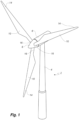
- Fig. 1 illustrates a conventional modern upwind wind turbine 2 according to the so-called "Danish concept" with a tower 4, a nacelle 6 and a rotor with a substantially horizontal rotor shaft.
- the rotor includes a hub 8 and three blades 10 extending radially from the hub 8, each having a blade root 16 nearest the hub and a blade tip 14 furthest from the hub 8, the blade extending in a spanwise direction between the root 16 and the tip 14.
- the rotor has a radius denoted R.
- Fig. 2 shows a schematic view of a wind turbine blade 10.
- the wind turbine blade 10 has the shape of a conventional wind turbine blade and comprises a root region 30 closest to the hub, a profiled or an airfoil region 34 furthest away from the hub and a transition region 32 between the root region 30 and the airfoil region 34.
- the blade 10 comprises a leading edge 18 facing the direction of rotation of the blade 10, when the blade is mounted on the hub, and a trailing edge 20 facing the opposite direction of the leading edge 18.
- An array of trailing edge serrations 21 are provided along a portion of the trailing edge 20 of the blade. In general, flow of air over the wind turbine blade 10 extends from the leading edge 18 to the trailing edge 20 in a generally transverse or chordwise direction.
- Fig. 2 While the serrations in Fig. 2 are depicted as being arranged along a middle portion of the blade, it is recognised that the serrations may be arranged for instance closer to the tip of the blade 10, or that they may be arranged along for instance the entire airfoil region 34 of the blade 10.
- the airfoil region 34 (also called the profiled region) has an ideal or almost ideal blade shape with respect to generating lift, whereas the root region 30 due to structural considerations has a substantially circular or elliptical cross-section, which for instance makes it easier and safer to mount the blade 10 to the hub.
- the diameter (or the chord) of the root region 30 is typically constant along the entire root area 30.
- the transition region 32 has a transitional profile 42 gradually changing from the circular or elliptical shape 40 of the root region 30 to the airfoil profile 50 of the airfoil region 34.
- the chord length of the transition region 32 typically increases substantially linearly with increasing distance r from the hub.
- the airfoil region 34 has an airfoil profile 50 with a chord extending between the leading edge 18 and the trailing edge 20 of the blade 10. The width of the chord decreases with increasing distance r from the hub.
- chords of different sections of the blade normally do not lie in a common plane, since the blade may be twisted and/or curved (i.e. pre-bent), thus providing the chord plane with a correspondingly twisted and/or curved course, this being most often the case in order to compensate for the local velocity of the blade being dependent on the radius from the hub.
- Fig. 3 shows a schematic view of an airfoil profile 50 of a typical blade of a wind turbine depicted with the various parameters, which are typically used to define the geometrical shape of an airfoil.
- the airfoil profile 50 has a pressure side 52 and a suction side 54, which during use - i.e. during rotation of the rotor - normally face towards the windward (or upwind) side and the leeward (or downwind) side, respectively.
- the airfoil 50 has a chord 60 with a chord length c extending between a leading edge 56 and a trailing edge 58 of the blade.
- the airfoil 50 has a thickness t, which is defined as the distance between the pressure side 52 and the suction side 54.
- the thickness t of the airfoil varies along the chord 60.
- the deviation from a symmetrical profile is given by a camber line 62, which is a median line through the airfoil profile 50.
- the median line can be found by drawing inscribed circles from the leading edge 56 to the trailing edge 58.
- the median line follows the centres of these inscribed circles and the deviation or distance from the chord 60 is called the camber f .
- the asymmetry can also be defined by use of parameters called the upper camber (or suction side camber) and lower camber (or pressure side camber), which are defined as the distances from the chord 60 and the suction side 54 and pressure side 52, respectively.
- Airfoil profiles are often characterised by the following parameters: the chord length c , the maximum camber f , the position d f of the maximum camber f , the maximum airfoil thickness t , which is the largest diameter of the inscribed circles along the median camber line 62, the position d t of the maximum thickness t , and a nose radius (not shown). These parameters are typically defined as ratios to the chord length c . Thus, a local relative blade thickness t / c is given as the ratio between the local maximum thickness t and the local chord length c . Further, the position d p of the maximum pressure side camber may be used as a design parameter, and of course also the position of the maximum suction side camber.
- Fig. 4 shows some other geometric parameters of the blade.
- the diameter of the root is defined as D.
- the blade is provided with a pre-bend, which is defined as ⁇ y, which corresponds to the out of plane deflection from a pitch axis 22 of the blade.
- the wind turbine blade 10 generally comprises a shell made of fibre-reinforced polymer, and is typically made as a pressure side or upwind shell part 24 and a suction side or downwind shell part 26 that are glued together along bond lines 28 extending along the trailing edge 20 and the leading edge 18 of the blade 10.
- Wind turbine blades are generally formed from fibre-reinforced plastics material, e.g. glass fibres and/or carbon fibres which are arranged in a mould and cured with a resin to form a solid structure. Modern wind turbine blades can often be in excess of 30 or 40 metres in length, having blade root diameters of several metres. Wind turbine blades are generally designed for relatively long lifetimes and to withstand considerable structural and dynamic loading.
- the serrations 100 comprise a base end 102 which is arranged at the trailing edge 20 of the wind turbine blade 10, and a tip end 104 which extends downwind of the blade trailing edge 20.
- a notional line extending from a midpoint of the base 102 to the apex or tip end 104 defines a height H of the serration.
- the illustrated serrations are substantially planar, but it will be understood that the serrations may vary in depth or thickness, in particular having tapered or chamfered edges.
- the serrations 100 are shown as having a profile substantially corresponding to an isosceles triangle, but it will be understood that other serration shape profiles may be used, e.g. curved or wave-shaped profiles, crenelated edges, etc.
- the serrations 100a, 100b, 100c are provided with splitter plates 106a, 106b, each having a diamond shaped surface.
- Each of the splitter plates 106a, 106b has an acute angle vertex 114a, 114b extending into said space in between adjacent serrations 100a, 100b, 100c to mitigate noise during operation of the wind turbine with the serrated trailing edge blade.
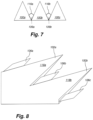
- Fig. 7 shows another embodiment of the splitter plate arrangement of the present invention.
- the serrations 100a, 100b, 100c are provided with splitter plates 106a, 106b, each having a kite shaped surface.
- each of the splitter plates 106a, 106b has an obtuse angle vertex 116a, 116b extending into said space in between adjacent serrations 100a, 100b, 100c.
- the serrations 100a, 100b and the splitter plates 106a, 106b, 106c define respective planes which are oriented substantially parallel to each other.
- a splitter plate is arranged between each of two adjacent serrations.
- the top surfaces 118a, 118b and respective bottom surfaces (not shown) of the serrations taper toward the apex end of the serrations.
- the plane of the splitter plates 106a, 106b, 106c is oriented at a small angle to the top surface 118a, 118b and to the bottom surface of the serrations, i.e.
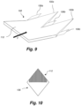
- the serrations 100a, 100b and the splitter plates 106a, 106b, 106c are provided as part of a trailing edge panel 108 for attachment to the trailing edge 20 of a wind turbine blade 10.
- the panel 108 comprises a base section 110 for attachment to the blade 10, with the serrations 100a, 100b arranged at an angle to the base section 110 such that the serrations 100 are arranged at incidence to the air flow over the wind turbine blade 10.
- the direction of air flow over the wind turbine blade is generally indicated by the arrow F.
- splitter plates 106 may be formed integrally as part of the serrations 100, e.g. as part of a moulding process, in further aspects the splitter plates 106 may be provided as separate add-on elements which can be attached to serrations 100.
- the add-ons may be provided as slotted elements which can be slid onto a serration from the end of the serration, and may be secured to the serration using any suitable means, e.g. adhesive bonding and/or a mechanical clip-on or snap-fit connection, based on interlocking elements provided on the serration and the add-ons.
- the splitter plates of the present invention may comprises one or more slits and/or holes.
- An example embodiment of this is shown in Figure 10 , in which the splitter plate 106 comprises streamwise comb-like stiff structures 112. This has been found to reduce load on the arrangement during operation.
- the invention is not limited to the embodiments described herein, and may be modified or adapted without departing from the scope of the present invention.
- the shape of the splitter plate may for instance take many different shapes such as a flat or smooth distal part. Further, the splitter plate may be designed with for instance two or three apex points (or smaller serrations) instead of the shown one apex point.
Landscapes
- Engineering & Computer Science (AREA)
- Life Sciences & Earth Sciences (AREA)
- Sustainable Development (AREA)
- Sustainable Energy (AREA)
- Chemical & Material Sciences (AREA)
- Combustion & Propulsion (AREA)
- Mechanical Engineering (AREA)
- General Engineering & Computer Science (AREA)
- Physics & Mathematics (AREA)
- Fluid Mechanics (AREA)
- Wind Motors (AREA)
Claims (14)
- Windkraftanlagenflügel (10) mit einer Profilkontur, umfassend eine Druckseite und eine Saugseite und eine Eintrittskante (18) und eine Austrittskante (20) mit einer sich dazwischen erstreckenden, eine Sehnenlänge aufweisenden Sehne, wobei sich der Windkraftanlagenflügel (10) in einer Spannweitenrichtung zwischen einem Wurzelende und einem Spitzenende erstreckt, wobei der Windkraftanlagenflügel eine Vielzahl von Zähnen (100) umfasst, die entlang mindestens eines Abschnitts der Austrittskante (20) des Flügels (10) bereitgestellt sind,wobei der Windkraftanlagenflügel ferner eine oder mehrere Trennplatten (106a, 106b) umfasst, wobei die Trennplatten jeweils dazu angeordnet sind, sich mindestens teilweise in einen Zwischenraum zwischen benachbarten Zähnen (100a, 100b, 100c) zu erstrecken, undwobei eine Dicke der einen oder der mehreren Trennplatten (106a, 106b) geringer ist als eine Dicke mindestens eines Teils benachbarter Zähne,wobei die Trennplatte (106a) eine Spitze umfasst, vorzugsweise eine spitzwinklige Spitze (114a), die sich in den Zwischenraum zwischen benachbarten Zähnen (100a, 100b) erstreckt.
- Windkraftanlagenflügel nach Anspruch 1, wobei die eine oder die mehreren Trennplatten (106a, 106b) zwischen benachbarten Zähnen angeordnet und vorzugsweise damit verbunden sind, wobei zum Beispiel die Trennplatten (106a, 106b) zwischen einer ersten Seitenwand eines ersten Zahns und einer zweiten Seitenwand eines zweiten Zahns verbunden sind.
- Windkraftanlagenflügel nach einem der Ansprüche 1-2, wobei Seitenwände der Zähne eine Seitenwanddicke aufweisen und eine Plattendicke der Trennplatte (106a, 106b) geringer ist als die Seitenwanddicke, wobei zum Beispiel das Verhältnis der Seitenwanddicke und der Plattendicke mindestens 2 : 1 oder mindestens 5 : 2 oder mindestens 3 : 1 beträgt.
- Windkraftanlagenflügel nach einem der vorangehenden Ansprüche, wobei die Trennplatte eine im Wesentlichen gleichmäßige Dicke aufweist.
- Windkraftanlagenflügel nach einem der vorangehenden Ansprüche, wobei die Zähne (100a, 100b, 100c) und die Trennplatten (106a, 106b) entsprechende Ebenen definieren, die im Wesentlichen parallel zueinander orientiert sind.
- Windkraftanlagenflügel nach einem der vorangehenden Ansprüche, wobei die Zähne (100) eine Basis (102) proximal der Austrittskante (20) des Flügels (10) und einen Scheitel (104) distal der Austrittskante (20) des Flügels (10) umfassen, wobei eine imaginäre Linie, die sich von einem Mittelpunkt der Basis (102) zu dem Scheitel (104) erstreckt, eine Höhe H des Zahns definiert und wobei sich die mindestens eine Trennplatte um eine Strecke von 60 % oder weniger, vorzugsweise 50 % oder weniger der Höhe (H) der Austrittskantenzähne (100) in einen Zwischenraum zwischen benachbarten Zähnen erstreckt.
- Windkraftanlagenflügel nach einem der vorangehenden Ansprüche, wobei die Trennplatten (106a, 106b) einstückig mit den Zähnen (100) gebildet sind oder wobei die Trennplatten (106a, 106b) als Anbauelemente bereitgestellt sind, die dazu angeordnet sind, an den Zähnen (100) befestigt zu werden.
- Windkraftanlagenflügel nach einem der vorangehenden Ansprüche, wobei die Trennplatten (106a, 106b) unter Verwendung von Kleben und/oder einer ineinandergreifenden Schnapp- oder Aufsteckverbindung an den Zähnen (100) befestigt sind.
- Windkraftanlagenflügel nach einem der vorangehenden Ansprüche, wobei die Dicke der Trennplatte 2,0 mm oder weniger, vorzugsweise 1,5 mm oder weniger beträgt.
- Windkraftanlagenflügel nach einem der vorangehenden Ansprüche, wobei die Trennplatte (106) eine parallelogrammförmige Oberfläche, vorzugsweise zwei gegenüberliegende parallelogrammförmige Oberflächen umfasst, wobei optionaldie Trennplatte (106) zwei gegenüberliegende rautenförmige Oberflächen umfasst und wobei ferner optionalsich ein spitzer Winkel der rautenförmigen Oberfläche in den Zwischenraum zwischen benachbarten Zähnen (100a, 100b) erstreckt.
- Windkraftanlagenflügel nach einem der Ansprüche 1-10, wobei die Trennplatte (106) eine drachenförmige Oberfläche, vorzugsweise zwei gegenüberliegende drachenförmige Oberflächen umfasst, oder wobei die Trennplatte (106) eine dreiecksförmige Oberfläche, vorzugsweise zwei gegenüberliegende dreiecksförmige Oberflächen umfasst.
- Windkraftanlagenflügel nach einem der vorangehenden Ansprüche, wobei die Trennplatte (106) einen oder mehrere Schlitze und/oder ein oder mehrere Löcher umfasst, wobei z. B. die Schlitze der Trennplatte eine Breite von 0,2 mm bis 2,0 mm aufweisen.
- Gezahntes Plattenelement (108) für einen Windkraftanlagenflügel, wobei das Plattenelement (108) dazu angeordnet ist, an der Austrittskante eines Flügels befestigt zu werden, um eine Vielzahl von Zähnen (100a, 100b) an der Austrittskante des Flügels zu bilden,wobei das Plattenelement (108) ferner eine oder mehrere Trennplatten (106a, 106b, 106c) umfasst, wobei die Trennplatten jeweils dazu angeordnet sind, sich mindestens teilweise in einen Zwischenraum zwischen benachbarten Zähnen (100a, 100b) zu erstrecken, undwobei eine Dicke der einen oder der mehreren Trennplatten (106a, 106b) geringer ist als eine Dicke mindestens eines Teils benachbarter Zähne,wobei die Trennplatte (106a) eine Spitze umfasst, vorzugsweise eine spitzwinklige Spitze (114a), die sich in den Zwischenraum zwischen benachbarten Zähnen (100a, 100b) erstreckt.
- Windkraftanlage, die mindestens einen Windkraftanlagenflügel nach einem der Ansprüche 1-12 umfasst.
Applications Claiming Priority (2)
| Application Number | Priority Date | Filing Date | Title |
|---|---|---|---|
| EP15200683.9A EP3181895A1 (de) | 2015-12-17 | 2015-12-17 | Teilerplattenanordnung für gezahnte windturbinenschaufel |
| PCT/EP2016/081558 WO2017103192A1 (en) | 2015-12-17 | 2016-12-16 | Splitter plate arrangement for a serrated wind turbine blade |
Publications (3)
| Publication Number | Publication Date |
|---|---|
| EP3390812A1 EP3390812A1 (de) | 2018-10-24 |
| EP3390812B1 EP3390812B1 (de) | 2020-07-22 |
| EP3390812B2 true EP3390812B2 (de) | 2025-06-04 |
Family
ID=54936842
Family Applications (2)
| Application Number | Title | Priority Date | Filing Date |
|---|---|---|---|
| EP15200683.9A Withdrawn EP3181895A1 (de) | 2015-12-17 | 2015-12-17 | Teilerplattenanordnung für gezahnte windturbinenschaufel |
| EP16816661.9A Active EP3390812B2 (de) | 2015-12-17 | 2016-12-16 | Teilerplattenanordnung für gezahnte windturbinenschaufel |
Family Applications Before (1)
| Application Number | Title | Priority Date | Filing Date |
|---|---|---|---|
| EP15200683.9A Withdrawn EP3181895A1 (de) | 2015-12-17 | 2015-12-17 | Teilerplattenanordnung für gezahnte windturbinenschaufel |
Country Status (5)
| Country | Link |
|---|---|
| US (1) | US11067057B2 (de) |
| EP (2) | EP3181895A1 (de) |
| CN (1) | CN108603485B (de) |
| DK (1) | DK3390812T4 (de) |
| WO (1) | WO2017103192A1 (de) |
Families Citing this family (7)
| Publication number | Priority date | Publication date | Assignee | Title |
|---|---|---|---|---|
| DK3431754T3 (da) * | 2016-02-12 | 2020-10-26 | Lm Wp Patent Holding As | Savtakket bagkantspanel til en vindmøllevinge |
| EP3426914B1 (de) * | 2016-04-15 | 2021-03-17 | Siemens Gamesa Renewable Energy A/S | Rotorblatt mit einer gezackten hinterkante |
| EP3584436A1 (de) * | 2018-06-18 | 2019-12-25 | Nordex Energy GmbH | Windenergieanlagenrotorblatt mit dicker und dünner hinterkante |
| EP3587798B1 (de) * | 2018-06-27 | 2020-10-14 | Siemens Gamesa Renewable Energy A/S | Aerodynamische struktur |
| ES3037885T3 (en) | 2018-06-27 | 2025-10-07 | Siemens Gamesa Renewable Energy As | Aerodynamic structure |
| US10746157B2 (en) | 2018-08-31 | 2020-08-18 | General Electric Company | Noise reducer for a wind turbine rotor blade having a cambered serration |
| KR102192061B1 (ko) * | 2019-12-30 | 2020-12-16 | 서울대학교산학협력단 | 블레이드 소음 저감 장치 |
Family Cites Families (70)
| Publication number | Priority date | Publication date | Assignee | Title |
|---|---|---|---|---|
| USRE19412E (en) * | 1935-01-01 | Aircraft and control thereof | ||
| US175355A (en) * | 1876-03-28 | Waltee king | ||
| US573562A (en) * | 1896-12-22 | Propeller | ||
| US1861065A (en) * | 1930-08-18 | 1932-05-31 | Poot Philippe | Screw-propeller for flying machines and other aerodynamics apparatus |
| US2071012A (en) * | 1932-11-22 | 1937-02-16 | Adams Herbert Luther | Noiseless device |
| US2238749A (en) * | 1939-01-30 | 1941-04-15 | Clarence B Swift | Fan blade |
| US2616509A (en) * | 1946-11-29 | 1952-11-04 | Thomas Wilfred | Pneumatic airfoil |
| JPS5115210A (en) * | 1974-07-02 | 1976-02-06 | Rotoron Inc | Zatsuongenshono fuan |
| US4618313A (en) * | 1980-02-06 | 1986-10-21 | Cofimco S.R.L. | Axial propeller with increased effective displacement of air whose blades are not twisted |
| US5088665A (en) * | 1989-10-31 | 1992-02-18 | The United States Of America As Represented By The Administrator Of The National Aeronautics And Space Administration | Serrated trailing edges for improving lift and drag characteristics of lifting surfaces |
| US5320491A (en) * | 1992-07-09 | 1994-06-14 | Northern Power Systems, Inc. | Wind turbine rotor aileron |
| NL9301910A (nl) * | 1993-11-04 | 1995-06-01 | Stork Prod Eng | Windturbine. |
| US5522266A (en) * | 1993-11-30 | 1996-06-04 | Medex, Inc. | Low cost pressure transducer particularly for medical applications |
| CA2141529A1 (en) * | 1994-10-25 | 1996-04-26 | Frances Gould | Street sweeper brush assembly |
| DE10020177A1 (de) * | 2000-04-25 | 2001-11-08 | Daimler Chrysler Ag | Einrichtung zur Lärmminderung an Tragflügeln von Flugzeugen |
| BR0003706A (pt) * | 2000-05-30 | 2002-02-13 | Tecsis Tecnologia E Sist S Ava | Pá para ventilador axial de baixo ruìdo e alta eficiência |
| US6733240B2 (en) * | 2001-07-18 | 2004-05-11 | General Electric Company | Serrated fan blade |
| WO2003008800A1 (en) * | 2001-07-19 | 2003-01-30 | Neg Micon A/S | Wind turbine blade |
| US7059833B2 (en) * | 2001-11-26 | 2006-06-13 | Bonus Energy A/S | Method for improvement of the efficiency of a wind turbine rotor |
| US6872048B2 (en) * | 2001-11-26 | 2005-03-29 | Lennox Industries, Inc. | Fan with reduced noise generation |
| EP1338793A3 (de) * | 2002-02-22 | 2010-09-01 | Mitsubishi Heavy Industries, Ltd. | Gezahnte Windturbinenflügelhinterkante |
| WO2004088130A1 (en) * | 2003-03-31 | 2004-10-14 | Forskningscenter Risø | Control of power, loads and/or stability of a horizontal axis wind turbine by use of variable blade geometry control |
| US7637721B2 (en) * | 2005-07-29 | 2009-12-29 | General Electric Company | Methods and apparatus for producing wind energy with reduced wind turbine noise |
| AU2006299847A1 (en) * | 2005-08-22 | 2007-04-19 | Viryd Technologies Inc. | Fluid energy converter |
| ES2318925B1 (es) * | 2005-09-22 | 2010-02-11 | GAMESA INNOVATION & TECHNOLOGY, S.L. | Aerogenerador con un rotor de palas que reduce el ruido. |
| US7458777B2 (en) * | 2005-09-22 | 2008-12-02 | General Electric Company | Wind turbine rotor assembly and blade having acoustic flap |
| DK176352B1 (da) * | 2005-12-20 | 2007-09-10 | Lm Glasfiber As | Profilserie til vinge til vindenergianlæg |
| US7959412B2 (en) * | 2006-09-29 | 2011-06-14 | General Electric Company | Wind turbine rotor blade with acoustic lining |
| US7811063B2 (en) * | 2006-11-03 | 2010-10-12 | General Electric Company | Damping element for a wind turbine rotor blade |
| US20080166241A1 (en) * | 2007-01-04 | 2008-07-10 | Stefan Herr | Wind turbine blade brush |
| US7918653B2 (en) * | 2007-02-07 | 2011-04-05 | General Electric Company | Rotor blade trailing edge assemby and method of use |
| US7413408B1 (en) * | 2007-02-22 | 2008-08-19 | Samuel B Tafoya | Vibration-reducing and noise-reducing spoiler for helicopter rotors, aircraft wings, propellers, and turbine blades |
| ES2345583B1 (es) * | 2007-05-31 | 2011-07-28 | GAMESA INNOVATION & TECHNOLOGY, S.L. | Pala de aerogenerador con dispositivos anti-ruido. |
| US7927078B2 (en) * | 2007-07-12 | 2011-04-19 | General Electric Company | Wind turbine blade tip vortex breakers |
| EP2031244A1 (de) * | 2007-08-31 | 2009-03-04 | Lm Glasfiber A/S | Mittel zur Bewahrung des Flusses eines an die Außenseite einer Durchflussreglerelements befestigten strömenden Mediums mittels Verwendung von Kreuzungsunterkanälen |
| US20090074585A1 (en) * | 2007-09-19 | 2009-03-19 | General Electric Company | Wind turbine blades with trailing edge serrations |
| KR101204199B1 (ko) * | 2008-08-06 | 2012-11-26 | 미츠비시 쥬고교 가부시키가이샤 | 풍차 날개 및 이를 이용하는 풍력 발전 장치 |
| US9239039B2 (en) * | 2008-10-27 | 2016-01-19 | General Electric Company | Active circulation control of aerodynamic structures |
| EP2253839A1 (de) * | 2009-05-18 | 2010-11-24 | Lm Glasfiber A/S | Windturbinenschaufel mit Flusswechselelementen |
| WO2010141720A2 (en) * | 2009-06-03 | 2010-12-09 | Flodesign Wind Turbine Corp. | Wind turbine blades with mixer lobes |
| US7976276B2 (en) * | 2010-11-04 | 2011-07-12 | General Electric Company | Noise reducer for rotor blade in wind turbine |
| US7976283B2 (en) * | 2010-11-10 | 2011-07-12 | General Electric Company | Noise reducer for rotor blade in wind turbine |
| US8267657B2 (en) * | 2010-12-16 | 2012-09-18 | General Electric Company | Noise reducer for rotor blade in wind turbine |
| ES2618459T3 (es) * | 2011-05-16 | 2017-06-21 | Lm Wp Patent Holding A/S | Pala de turbina eólica con dispositivos de reducción de ruido y un método relacionado |
| US8414261B2 (en) * | 2011-05-31 | 2013-04-09 | General Electric Company | Noise reducer for rotor blade in wind turbine |
| WO2013045601A1 (en) * | 2011-09-29 | 2013-04-04 | Lm Wind Power A/S | A wind turbine blade |
| EP2783103B1 (de) * | 2011-11-23 | 2017-01-04 | LM WP Patent Holding A/S | Windturbinenblatt |
| US9341158B2 (en) * | 2011-12-08 | 2016-05-17 | Inventus Holdings, Llc | Quiet wind turbine blade |
| GB2497739A (en) * | 2011-12-19 | 2013-06-26 | Rolls Royce Plc | Rotor blade with serrated trailing edge |
| DK2679803T3 (en) * | 2012-06-28 | 2017-05-15 | Nordex Energy Gmbh | Rotor blade for wind energy systems and with a thick profile rear edge |
| US9458821B2 (en) * | 2012-09-11 | 2016-10-04 | General Electric Company | Attachment system for a wind turbine rotor blade accessory |
| WO2014048437A1 (en) * | 2012-09-25 | 2014-04-03 | Vestas Wind Systems A/S | Noise attenuator for a wind turbine blade and a method for reducing wind turbine noise |
| GB2514214B (en) * | 2012-09-25 | 2015-04-22 | Messier Dowty Ltd | Aircraft component noise reducing patch |
| DK2929178T3 (en) * | 2012-12-07 | 2018-06-18 | Wobben Properties Gmbh | Rotor wing rear edge |
| NL2011236C2 (en) * | 2013-07-30 | 2015-02-02 | Stichting Energie | Rotor blade for a wind turbine, and wind turbine field. |
| EP2851554A1 (de) * | 2013-09-18 | 2015-03-25 | Siemens Aktiengesellschaft | Anordnung zur Minderung der Schallemission |
| US9638164B2 (en) * | 2013-10-31 | 2017-05-02 | General Electric Company | Chord extenders for a wind turbine rotor blade assembly |
| US9494134B2 (en) * | 2013-11-20 | 2016-11-15 | General Electric Company | Noise reducing extension plate for rotor blade in wind turbine |
| ES2848858T3 (es) * | 2014-08-05 | 2021-08-12 | Biomerenewables Inc | Pala de rotor de turbinas eólicas |
| US9849976B2 (en) * | 2014-08-19 | 2017-12-26 | The Boeing Company | Noise reducing profile for helicopter rotor blade tracking wedges |
| GB201512688D0 (en) * | 2015-07-20 | 2015-08-26 | Rolls Royce Plc | Aerofoil |
| US10421533B2 (en) * | 2015-11-06 | 2019-09-24 | Lockheed Martin Corporation | Panels comprising uneven edge patterns for reducing boundary layer separation |
| US10240576B2 (en) * | 2015-11-25 | 2019-03-26 | General Electric Company | Wind turbine noise reduction with acoustically absorbent serrations |
| US10460717B2 (en) * | 2015-12-18 | 2019-10-29 | Amazon Technologies, Inc. | Carbon nanotube transducers on propeller blades for sound control |
| US10011346B2 (en) * | 2015-12-18 | 2018-07-03 | Amazon Technologies, Inc. | Propeller blade indentations for improved aerodynamic performance and sound control |
| US10259574B2 (en) * | 2015-12-18 | 2019-04-16 | Amazon Technologies, Inc. | Propeller surface area treatments for sound dampening |
| US10099773B2 (en) * | 2015-12-18 | 2018-10-16 | Amazon Technologies, Inc. | Propeller blade leading edge serrations for improved sound control |
| US10259562B2 (en) * | 2015-12-18 | 2019-04-16 | Amazon Technologies, Inc. | Propeller blade trailing edge fringes for improved sound control |
| US10400744B2 (en) * | 2016-04-28 | 2019-09-03 | General Electric Company | Wind turbine blade with noise reducing micro boundary layer energizers |
| US10465652B2 (en) * | 2017-01-26 | 2019-11-05 | General Electric Company | Vortex generators for wind turbine rotor blades having noise-reducing features |
-
2015
- 2015-12-17 EP EP15200683.9A patent/EP3181895A1/de not_active Withdrawn
-
2016
- 2016-12-16 DK DK16816661.9T patent/DK3390812T4/da active
- 2016-12-16 WO PCT/EP2016/081558 patent/WO2017103192A1/en not_active Ceased
- 2016-12-16 CN CN201680082127.XA patent/CN108603485B/zh active Active
- 2016-12-16 US US16/062,342 patent/US11067057B2/en active Active
- 2016-12-16 EP EP16816661.9A patent/EP3390812B2/de active Active
Also Published As
| Publication number | Publication date |
|---|---|
| EP3181895A1 (de) | 2017-06-21 |
| WO2017103192A1 (en) | 2017-06-22 |
| US11067057B2 (en) | 2021-07-20 |
| EP3390812B1 (de) | 2020-07-22 |
| EP3390812A1 (de) | 2018-10-24 |
| DK3390812T3 (da) | 2020-10-26 |
| DK3390812T4 (da) | 2025-09-08 |
| US20200277931A1 (en) | 2020-09-03 |
| CN108603485A (zh) | 2018-09-28 |
| CN108603485B (zh) | 2021-01-12 |
Similar Documents
| Publication | Publication Date | Title |
|---|---|---|
| US11053911B2 (en) | Serrated trailing edge panel for a wind turbine blade | |
| EP3390812B2 (de) | Teilerplattenanordnung für gezahnte windturbinenschaufel | |
| US10781788B2 (en) | Wind turbine blade | |
| US20110243753A1 (en) | Wind turbine blade having a flow guiding device with optimised height | |
| US20110250076A1 (en) | Wind turbine blade having a spoiler with effective separation of airflow | |
| US11661918B2 (en) | Noise reducer for a wind turbine rotor blade | |
| WO2025210224A1 (en) | Serrated trailing edge panel for a wind turbine blade | |
| EP2851557A1 (de) | Windturbinenblatt mit aerodynamischen Klappen am Blattanfang |
Legal Events
| Date | Code | Title | Description |
|---|---|---|---|
| STAA | Information on the status of an ep patent application or granted ep patent |
Free format text: STATUS: UNKNOWN |
|
| STAA | Information on the status of an ep patent application or granted ep patent |
Free format text: STATUS: THE INTERNATIONAL PUBLICATION HAS BEEN MADE |
|
| PUAI | Public reference made under article 153(3) epc to a published international application that has entered the european phase |
Free format text: ORIGINAL CODE: 0009012 |
|
| STAA | Information on the status of an ep patent application or granted ep patent |
Free format text: STATUS: REQUEST FOR EXAMINATION WAS MADE |
|
| 17P | Request for examination filed |
Effective date: 20180717 |
|
| AK | Designated contracting states |
Kind code of ref document: A1 Designated state(s): AL AT BE BG CH CY CZ DE DK EE ES FI FR GB GR HR HU IE IS IT LI LT LU LV MC MK MT NL NO PL PT RO RS SE SI SK SM TR |
|
| AX | Request for extension of the european patent |
Extension state: BA ME |
|
| RIN1 | Information on inventor provided before grant (corrected) |
Inventor name: ARCE, CARLOS |
|
| DAX | Request for extension of the european patent (deleted) | ||
| RAV | Requested validation state of the european patent: fee paid |
Extension state: MA Effective date: 20180717 |
|
| GRAP | Despatch of communication of intention to grant a patent |
Free format text: ORIGINAL CODE: EPIDOSNIGR1 |
|
| STAA | Information on the status of an ep patent application or granted ep patent |
Free format text: STATUS: GRANT OF PATENT IS INTENDED |
|
| INTG | Intention to grant announced |
Effective date: 20200213 |
|
| GRAS | Grant fee paid |
Free format text: ORIGINAL CODE: EPIDOSNIGR3 |
|
| GRAA | (expected) grant |
Free format text: ORIGINAL CODE: 0009210 |
|
| STAA | Information on the status of an ep patent application or granted ep patent |
Free format text: STATUS: THE PATENT HAS BEEN GRANTED |
|
| AK | Designated contracting states |
Kind code of ref document: B1 Designated state(s): AL AT BE BG CH CY CZ DE DK EE ES FI FR GB GR HR HU IE IS IT LI LT LU LV MC MK MT NL NO PL PT RO RS SE SI SK SM TR |
|
| REG | Reference to a national code |
Ref country code: GB Ref legal event code: FG4D |
|
| REG | Reference to a national code |
Ref country code: CH Ref legal event code: EP |
|
| REG | Reference to a national code |
Ref country code: DE Ref legal event code: R096 Ref document number: 602016040538 Country of ref document: DE |
|
| REG | Reference to a national code |
Ref country code: AT Ref legal event code: REF Ref document number: 1293622 Country of ref document: AT Kind code of ref document: T Effective date: 20200815 |
|
| REG | Reference to a national code |
Ref country code: IE Ref legal event code: FG4D |
|
| REG | Reference to a national code |
Ref country code: NL Ref legal event code: FP |
|
| REG | Reference to a national code |
Ref country code: DK Ref legal event code: T3 Effective date: 20201019 |
|
| REG | Reference to a national code |
Ref country code: LT Ref legal event code: MG4D |
|
| REG | Reference to a national code |
Ref country code: AT Ref legal event code: MK05 Ref document number: 1293622 Country of ref document: AT Kind code of ref document: T Effective date: 20200722 |
|
| PG25 | Lapsed in a contracting state [announced via postgrant information from national office to epo] |
Ref country code: AT Free format text: LAPSE BECAUSE OF FAILURE TO SUBMIT A TRANSLATION OF THE DESCRIPTION OR TO PAY THE FEE WITHIN THE PRESCRIBED TIME-LIMIT Effective date: 20200722 Ref country code: FI Free format text: LAPSE BECAUSE OF FAILURE TO SUBMIT A TRANSLATION OF THE DESCRIPTION OR TO PAY THE FEE WITHIN THE PRESCRIBED TIME-LIMIT Effective date: 20200722 Ref country code: NO Free format text: LAPSE BECAUSE OF FAILURE TO SUBMIT A TRANSLATION OF THE DESCRIPTION OR TO PAY THE FEE WITHIN THE PRESCRIBED TIME-LIMIT Effective date: 20201022 Ref country code: GR Free format text: LAPSE BECAUSE OF FAILURE TO SUBMIT A TRANSLATION OF THE DESCRIPTION OR TO PAY THE FEE WITHIN THE PRESCRIBED TIME-LIMIT Effective date: 20201023 Ref country code: SE Free format text: LAPSE BECAUSE OF FAILURE TO SUBMIT A TRANSLATION OF THE DESCRIPTION OR TO PAY THE FEE WITHIN THE PRESCRIBED TIME-LIMIT Effective date: 20200722 Ref country code: BG Free format text: LAPSE BECAUSE OF FAILURE TO SUBMIT A TRANSLATION OF THE DESCRIPTION OR TO PAY THE FEE WITHIN THE PRESCRIBED TIME-LIMIT Effective date: 20201022 Ref country code: PT Free format text: LAPSE BECAUSE OF FAILURE TO SUBMIT A TRANSLATION OF THE DESCRIPTION OR TO PAY THE FEE WITHIN THE PRESCRIBED TIME-LIMIT Effective date: 20201123 Ref country code: HR Free format text: LAPSE BECAUSE OF FAILURE TO SUBMIT A TRANSLATION OF THE DESCRIPTION OR TO PAY THE FEE WITHIN THE PRESCRIBED TIME-LIMIT Effective date: 20200722 Ref country code: LT Free format text: LAPSE BECAUSE OF FAILURE TO SUBMIT A TRANSLATION OF THE DESCRIPTION OR TO PAY THE FEE WITHIN THE PRESCRIBED TIME-LIMIT Effective date: 20200722 Ref country code: ES Free format text: LAPSE BECAUSE OF FAILURE TO SUBMIT A TRANSLATION OF THE DESCRIPTION OR TO PAY THE FEE WITHIN THE PRESCRIBED TIME-LIMIT Effective date: 20200722 |
|
| PG25 | Lapsed in a contracting state [announced via postgrant information from national office to epo] |
Ref country code: IS Free format text: LAPSE BECAUSE OF FAILURE TO SUBMIT A TRANSLATION OF THE DESCRIPTION OR TO PAY THE FEE WITHIN THE PRESCRIBED TIME-LIMIT Effective date: 20201122 Ref country code: PL Free format text: LAPSE BECAUSE OF FAILURE TO SUBMIT A TRANSLATION OF THE DESCRIPTION OR TO PAY THE FEE WITHIN THE PRESCRIBED TIME-LIMIT Effective date: 20200722 Ref country code: LV Free format text: LAPSE BECAUSE OF FAILURE TO SUBMIT A TRANSLATION OF THE DESCRIPTION OR TO PAY THE FEE WITHIN THE PRESCRIBED TIME-LIMIT Effective date: 20200722 Ref country code: RS Free format text: LAPSE BECAUSE OF FAILURE TO SUBMIT A TRANSLATION OF THE DESCRIPTION OR TO PAY THE FEE WITHIN THE PRESCRIBED TIME-LIMIT Effective date: 20200722 |
|
| REG | Reference to a national code |
Ref country code: DE Ref legal event code: R026 Ref document number: 602016040538 Country of ref document: DE |
|
| PG25 | Lapsed in a contracting state [announced via postgrant information from national office to epo] |
Ref country code: SM Free format text: LAPSE BECAUSE OF FAILURE TO SUBMIT A TRANSLATION OF THE DESCRIPTION OR TO PAY THE FEE WITHIN THE PRESCRIBED TIME-LIMIT Effective date: 20200722 Ref country code: IT Free format text: LAPSE BECAUSE OF FAILURE TO SUBMIT A TRANSLATION OF THE DESCRIPTION OR TO PAY THE FEE WITHIN THE PRESCRIBED TIME-LIMIT Effective date: 20200722 Ref country code: EE Free format text: LAPSE BECAUSE OF FAILURE TO SUBMIT A TRANSLATION OF THE DESCRIPTION OR TO PAY THE FEE WITHIN THE PRESCRIBED TIME-LIMIT Effective date: 20200722 Ref country code: RO Free format text: LAPSE BECAUSE OF FAILURE TO SUBMIT A TRANSLATION OF THE DESCRIPTION OR TO PAY THE FEE WITHIN THE PRESCRIBED TIME-LIMIT Effective date: 20200722 Ref country code: CZ Free format text: LAPSE BECAUSE OF FAILURE TO SUBMIT A TRANSLATION OF THE DESCRIPTION OR TO PAY THE FEE WITHIN THE PRESCRIBED TIME-LIMIT Effective date: 20200722 |
|
| PLBI | Opposition filed |
Free format text: ORIGINAL CODE: 0009260 |
|
| PLAX | Notice of opposition and request to file observation + time limit sent |
Free format text: ORIGINAL CODE: EPIDOSNOBS2 |
|
| PG25 | Lapsed in a contracting state [announced via postgrant information from national office to epo] |
Ref country code: AL Free format text: LAPSE BECAUSE OF FAILURE TO SUBMIT A TRANSLATION OF THE DESCRIPTION OR TO PAY THE FEE WITHIN THE PRESCRIBED TIME-LIMIT Effective date: 20200722 |
|
| VS25 | Lapsed in a validation state [announced via postgrant information from nat. office to epo] |
Ref country code: MA Free format text: LAPSE BECAUSE OF FAILURE TO SUBMIT A TRANSLATION OF THE DESCRIPTION OR TO PAY THE FEE WITHIN THE PRESCRIBED TIME-LIMIT Effective date: 20200722 |
|
| 26 | Opposition filed |
Opponent name: VESTAS WIND SYSTEMS A/S Effective date: 20210422 |
|
| PG25 | Lapsed in a contracting state [announced via postgrant information from national office to epo] |
Ref country code: SK Free format text: LAPSE BECAUSE OF FAILURE TO SUBMIT A TRANSLATION OF THE DESCRIPTION OR TO PAY THE FEE WITHIN THE PRESCRIBED TIME-LIMIT Effective date: 20200722 |
|
| REG | Reference to a national code |
Ref country code: CH Ref legal event code: PL |
|
| PG25 | Lapsed in a contracting state [announced via postgrant information from national office to epo] |
Ref country code: SI Free format text: LAPSE BECAUSE OF FAILURE TO SUBMIT A TRANSLATION OF THE DESCRIPTION OR TO PAY THE FEE WITHIN THE PRESCRIBED TIME-LIMIT Effective date: 20200722 Ref country code: MC Free format text: LAPSE BECAUSE OF FAILURE TO SUBMIT A TRANSLATION OF THE DESCRIPTION OR TO PAY THE FEE WITHIN THE PRESCRIBED TIME-LIMIT Effective date: 20200722 |
|
| REG | Reference to a national code |
Ref country code: BE Ref legal event code: MM Effective date: 20201231 |
|
| PLBB | Reply of patent proprietor to notice(s) of opposition received |
Free format text: ORIGINAL CODE: EPIDOSNOBS3 |
|
| PG25 | Lapsed in a contracting state [announced via postgrant information from national office to epo] |
Ref country code: LU Free format text: LAPSE BECAUSE OF NON-PAYMENT OF DUE FEES Effective date: 20201216 Ref country code: IE Free format text: LAPSE BECAUSE OF NON-PAYMENT OF DUE FEES Effective date: 20201216 |
|
| PG25 | Lapsed in a contracting state [announced via postgrant information from national office to epo] |
Ref country code: CH Free format text: LAPSE BECAUSE OF NON-PAYMENT OF DUE FEES Effective date: 20201231 Ref country code: LI Free format text: LAPSE BECAUSE OF NON-PAYMENT OF DUE FEES Effective date: 20201231 |
|
| RAP2 | Party data changed (patent owner data changed or rights of a patent transferred) |
Owner name: LM WIND POWER A/S |
|
| PG25 | Lapsed in a contracting state [announced via postgrant information from national office to epo] |
Ref country code: TR Free format text: LAPSE BECAUSE OF FAILURE TO SUBMIT A TRANSLATION OF THE DESCRIPTION OR TO PAY THE FEE WITHIN THE PRESCRIBED TIME-LIMIT Effective date: 20200722 Ref country code: MT Free format text: LAPSE BECAUSE OF FAILURE TO SUBMIT A TRANSLATION OF THE DESCRIPTION OR TO PAY THE FEE WITHIN THE PRESCRIBED TIME-LIMIT Effective date: 20200722 Ref country code: CY Free format text: LAPSE BECAUSE OF FAILURE TO SUBMIT A TRANSLATION OF THE DESCRIPTION OR TO PAY THE FEE WITHIN THE PRESCRIBED TIME-LIMIT Effective date: 20200722 |
|
| PG25 | Lapsed in a contracting state [announced via postgrant information from national office to epo] |
Ref country code: MK Free format text: LAPSE BECAUSE OF FAILURE TO SUBMIT A TRANSLATION OF THE DESCRIPTION OR TO PAY THE FEE WITHIN THE PRESCRIBED TIME-LIMIT Effective date: 20200722 |
|
| PG25 | Lapsed in a contracting state [announced via postgrant information from national office to epo] |
Ref country code: BE Free format text: LAPSE BECAUSE OF NON-PAYMENT OF DUE FEES Effective date: 20201231 |
|
| APBM | Appeal reference recorded |
Free format text: ORIGINAL CODE: EPIDOSNREFNO |
|
| APBP | Date of receipt of notice of appeal recorded |
Free format text: ORIGINAL CODE: EPIDOSNNOA2O |
|
| APAH | Appeal reference modified |
Free format text: ORIGINAL CODE: EPIDOSCREFNO |
|
| APBM | Appeal reference recorded |
Free format text: ORIGINAL CODE: EPIDOSNREFNO |
|
| APBP | Date of receipt of notice of appeal recorded |
Free format text: ORIGINAL CODE: EPIDOSNNOA2O |
|
| P01 | Opt-out of the competence of the unified patent court (upc) registered |
Effective date: 20230522 |
|
| APBQ | Date of receipt of statement of grounds of appeal recorded |
Free format text: ORIGINAL CODE: EPIDOSNNOA3O |
|
| APBQ | Date of receipt of statement of grounds of appeal recorded |
Free format text: ORIGINAL CODE: EPIDOSNNOA3O |
|
| PGFP | Annual fee paid to national office [announced via postgrant information from national office to epo] |
Ref country code: NL Payment date: 20231121 Year of fee payment: 8 |
|
| APBU | Appeal procedure closed |
Free format text: ORIGINAL CODE: EPIDOSNNOA9O |
|
| PGFP | Annual fee paid to national office [announced via postgrant information from national office to epo] |
Ref country code: DE Payment date: 20241121 Year of fee payment: 9 |
|
| PGFP | Annual fee paid to national office [announced via postgrant information from national office to epo] |
Ref country code: DK Payment date: 20241121 Year of fee payment: 9 |
|
| PGFP | Annual fee paid to national office [announced via postgrant information from national office to epo] |
Ref country code: GB Payment date: 20241122 Year of fee payment: 9 |
|
| PGFP | Annual fee paid to national office [announced via postgrant information from national office to epo] |
Ref country code: FR Payment date: 20241121 Year of fee payment: 9 |
|
| PUAH | Patent maintained in amended form |
Free format text: ORIGINAL CODE: 0009272 |
|
| STAA | Information on the status of an ep patent application or granted ep patent |
Free format text: STATUS: PATENT MAINTAINED AS AMENDED |
|
| 27A | Patent maintained in amended form |
Effective date: 20250604 |
|
| AK | Designated contracting states |
Kind code of ref document: B2 Designated state(s): AL AT BE BG CH CY CZ DE DK EE ES FI FR GB GR HR HU IE IS IT LI LT LU LV MC MK MT NL NO PL PT RO RS SE SI SK SM TR |
|
| REG | Reference to a national code |
Ref country code: DE Ref legal event code: R102 Ref document number: 602016040538 Country of ref document: DE |
|
| REG | Reference to a national code |
Ref country code: NL Ref legal event code: MM Effective date: 20250101 |
|
| REG | Reference to a national code |
Ref country code: DK Ref legal event code: T4 Effective date: 20250901 |
|
| PG25 | Lapsed in a contracting state [announced via postgrant information from national office to epo] |
Ref country code: NL Free format text: LAPSE BECAUSE OF NON-PAYMENT OF DUE FEES Effective date: 20250101 |