EP3390790B1 - Heat insulation structure - Google Patents
Heat insulation structure Download PDFInfo
- Publication number
- EP3390790B1 EP3390790B1 EP15801891.1A EP15801891A EP3390790B1 EP 3390790 B1 EP3390790 B1 EP 3390790B1 EP 15801891 A EP15801891 A EP 15801891A EP 3390790 B1 EP3390790 B1 EP 3390790B1
- Authority
- EP
- European Patent Office
- Prior art keywords
- shell layer
- air
- heat insulation
- insulation structure
- outer shell
- Prior art date
- Legal status (The legal status is an assumption and is not a legal conclusion. Google has not performed a legal analysis and makes no representation as to the accuracy of the status listed.)
- Active
Links
Images
Classifications
-
- F—MECHANICAL ENGINEERING; LIGHTING; HEATING; WEAPONS; BLASTING
- F01—MACHINES OR ENGINES IN GENERAL; ENGINE PLANTS IN GENERAL; STEAM ENGINES
- F01N—GAS-FLOW SILENCERS OR EXHAUST APPARATUS FOR MACHINES OR ENGINES IN GENERAL; GAS-FLOW SILENCERS OR EXHAUST APPARATUS FOR INTERNAL-COMBUSTION ENGINES
- F01N13/00—Exhaust or silencing apparatus characterised by constructional features
- F01N13/08—Other arrangements or adaptations of exhaust conduits
- F01N13/10—Other arrangements or adaptations of exhaust conduits of exhaust manifolds
- F01N13/102—Other arrangements or adaptations of exhaust conduits of exhaust manifolds having thermal insulation
-
- F—MECHANICAL ENGINEERING; LIGHTING; HEATING; WEAPONS; BLASTING
- F01—MACHINES OR ENGINES IN GENERAL; ENGINE PLANTS IN GENERAL; STEAM ENGINES
- F01N—GAS-FLOW SILENCERS OR EXHAUST APPARATUS FOR MACHINES OR ENGINES IN GENERAL; GAS-FLOW SILENCERS OR EXHAUST APPARATUS FOR INTERNAL-COMBUSTION ENGINES
- F01N13/00—Exhaust or silencing apparatus characterised by constructional features
- F01N13/004—Exhaust or silencing apparatus characterised by constructional features specially adapted for marine propulsion, i.e. for receiving simultaneously engine exhaust gases and engine cooling water
-
- F—MECHANICAL ENGINEERING; LIGHTING; HEATING; WEAPONS; BLASTING
- F01—MACHINES OR ENGINES IN GENERAL; ENGINE PLANTS IN GENERAL; STEAM ENGINES
- F01N—GAS-FLOW SILENCERS OR EXHAUST APPARATUS FOR MACHINES OR ENGINES IN GENERAL; GAS-FLOW SILENCERS OR EXHAUST APPARATUS FOR INTERNAL-COMBUSTION ENGINES
- F01N13/00—Exhaust or silencing apparatus characterised by constructional features
- F01N13/14—Exhaust or silencing apparatus characterised by constructional features having thermal insulation
- F01N13/141—Double-walled exhaust pipes or housings
- F01N13/143—Double-walled exhaust pipes or housings with air filling the space between both walls
-
- F—MECHANICAL ENGINEERING; LIGHTING; HEATING; WEAPONS; BLASTING
- F02—COMBUSTION ENGINES; HOT-GAS OR COMBUSTION-PRODUCT ENGINE PLANTS
- F02B—INTERNAL-COMBUSTION PISTON ENGINES; COMBUSTION ENGINES IN GENERAL
- F02B37/00—Engines characterised by provision of pumps driven at least for part of the time by exhaust
- F02B37/02—Gas passages between engine outlet and pump drive, e.g. reservoirs
-
- F—MECHANICAL ENGINEERING; LIGHTING; HEATING; WEAPONS; BLASTING
- F01—MACHINES OR ENGINES IN GENERAL; ENGINE PLANTS IN GENERAL; STEAM ENGINES
- F01N—GAS-FLOW SILENCERS OR EXHAUST APPARATUS FOR MACHINES OR ENGINES IN GENERAL; GAS-FLOW SILENCERS OR EXHAUST APPARATUS FOR INTERNAL-COMBUSTION ENGINES
- F01N2260/00—Exhaust treating devices having provisions not otherwise provided for
- F01N2260/08—Exhaust treating devices having provisions not otherwise provided for for preventing heat loss or temperature drop, using other means than layers of heat-insulating material
-
- F—MECHANICAL ENGINEERING; LIGHTING; HEATING; WEAPONS; BLASTING
- F01—MACHINES OR ENGINES IN GENERAL; ENGINE PLANTS IN GENERAL; STEAM ENGINES
- F01N—GAS-FLOW SILENCERS OR EXHAUST APPARATUS FOR MACHINES OR ENGINES IN GENERAL; GAS-FLOW SILENCERS OR EXHAUST APPARATUS FOR INTERNAL-COMBUSTION ENGINES
- F01N2260/00—Exhaust treating devices having provisions not otherwise provided for
- F01N2260/20—Exhaust treating devices having provisions not otherwise provided for for heat or sound protection, e.g. using a shield or specially shaped outer surface of exhaust device
-
- F—MECHANICAL ENGINEERING; LIGHTING; HEATING; WEAPONS; BLASTING
- F01—MACHINES OR ENGINES IN GENERAL; ENGINE PLANTS IN GENERAL; STEAM ENGINES
- F01N—GAS-FLOW SILENCERS OR EXHAUST APPARATUS FOR MACHINES OR ENGINES IN GENERAL; GAS-FLOW SILENCERS OR EXHAUST APPARATUS FOR INTERNAL-COMBUSTION ENGINES
- F01N2310/00—Selection of sound absorbing or insulating material
- F01N2310/02—Mineral wool, e.g. glass wool, rock wool, asbestos or the like
-
- F—MECHANICAL ENGINEERING; LIGHTING; HEATING; WEAPONS; BLASTING
- F01—MACHINES OR ENGINES IN GENERAL; ENGINE PLANTS IN GENERAL; STEAM ENGINES
- F01N—GAS-FLOW SILENCERS OR EXHAUST APPARATUS FOR MACHINES OR ENGINES IN GENERAL; GAS-FLOW SILENCERS OR EXHAUST APPARATUS FOR INTERNAL-COMBUSTION ENGINES
- F01N2340/00—Dimensional characteristics of the exhaust system, e.g. length, diameter or volume of the exhaust apparatus; Spatial arrangements of exhaust apparatuses
- F01N2340/06—Arrangement of the exhaust apparatus relative to the turbine of a turbocharger
-
- F—MECHANICAL ENGINEERING; LIGHTING; HEATING; WEAPONS; BLASTING
- F01—MACHINES OR ENGINES IN GENERAL; ENGINE PLANTS IN GENERAL; STEAM ENGINES
- F01N—GAS-FLOW SILENCERS OR EXHAUST APPARATUS FOR MACHINES OR ENGINES IN GENERAL; GAS-FLOW SILENCERS OR EXHAUST APPARATUS FOR INTERNAL-COMBUSTION ENGINES
- F01N2590/00—Exhaust or silencing apparatus adapted to particular use, e.g. for military applications, airplanes, submarines
- F01N2590/02—Exhaust or silencing apparatus adapted to particular use, e.g. for military applications, airplanes, submarines for marine vessels or naval applications
-
- Y—GENERAL TAGGING OF NEW TECHNOLOGICAL DEVELOPMENTS; GENERAL TAGGING OF CROSS-SECTIONAL TECHNOLOGIES SPANNING OVER SEVERAL SECTIONS OF THE IPC; TECHNICAL SUBJECTS COVERED BY FORMER USPC CROSS-REFERENCE ART COLLECTIONS [XRACs] AND DIGESTS
- Y02—TECHNOLOGIES OR APPLICATIONS FOR MITIGATION OR ADAPTATION AGAINST CLIMATE CHANGE
- Y02T—CLIMATE CHANGE MITIGATION TECHNOLOGIES RELATED TO TRANSPORTATION
- Y02T10/00—Road transport of goods or passengers
- Y02T10/10—Internal combustion engine [ICE] based vehicles
- Y02T10/12—Improving ICE efficiencies
Definitions
- the present invention relates to a heat insulation structure for a component of an exhaust system of a piston engine as defined in claim 1.
- SOLAS International Convention for the Safety of Life at Sea
- Many of the standards concern the construction of the engines used in the ships.
- the requirements set by the major treaties can be fulfilled with conventional constructions, but in some cases the use or the operating conditions of a ship set requirements that are much more difficult to meet.
- One aspect that is regulated by SOLAS and concerns engines is the surface temperature of the exhaust system.
- the requirements of SOLAS can be met by a single insulation layer arranged around an exhaust gas receiver and a turbocharger, but in some cases much lower surface temperatures need to be achieved (see GB2045859A and DE2037135A1 ).
- An object of the present invention is to provide an improved heat insulation structure for a component of an exhaust system of a piston engine.
- the characterizing features of the heat insulation structure according to the invention are given in claim 1.
- the heat insulation structure according to the invention is arrangeable around a component of an exhaust system in such a manner that an air space is formed between the component and the heat insulation structure and comprises an outer shell layer, a middle shell layer that is arranged inside the outer shell layer, and a first inner shell layer that is arranged inside the middle shell layer, wherein a first air gap is arranged between the outer shell layer and the middle shell layer, a first insulation layer of insulation material is arranged between the middle shell layer and the first inner shell layer, and the outer shell layer is provided with venting apertures for natural ventilation of the first air gap.
- the surface temperatures of the heat insulation structure are significantly reduced compared to conventional heat insulation structures used in the exhaust systems of piston engines.
- Low surface temperature can be achieved without fans or additional insulation layers outside the outer shell layer.
- a lower part of the outer shell layer is provided with at least one air inlet for introducing venting air into the first air gap. Air inlets in the lower part and air outlets in the upper part of the outer shell layer create an effective venting air flow through the first air gap keeping the surface temperature of the outer shell layer low.
- the outer shell layer is provided with additional air inlets between the air inlets of the lower part and the air outlets.
- the additional air inlets enhance the ventilation of the first air gap.
- the cover structure prevents fuel spillages on surfaces at higher temperatures.
- the venting air can be released into the air immediately around the heat insulation structure.
- the location of the air outlets of the cover structure above the air outlets of the outer shell layer ensures that air flow through the first air gap is generated.
- the air outlets of the cover structure are arranged in a horizontal direction in relation to the air outlets of the outer shell layer such that a labyrinth structure for the venting air is formed.
- the labyrinth structure generates better air flow through the first air gap. It also ensures that possible fuel spillages on the cover structure do not reach directly the hotter surfaces inside the heat insulation structure via the air outlets.
- the air inlets of the cover structure improve air flow in the heat insulation structure.
- the heat insulation structure further comprises a second inner shell layer that is arranged inside the first inner shell layer, a third inner shell layer that is arranged inside the second inner shell layer, a second air gap that is arranged between the first inner shell layer and the second inner shell layer, and a second insulation layer of insulation material that is arranged between the second inner shell layer and the third inner shell layer.
- the further air gap and insulation layer improve the heat insulation.
- This heat insulation structure is suitable in particular for a turbine of a turbocharger. If the engine is provided with two-stage turbocharging, especially the high-pressure turbocharger may need an improved heat insulation structure with two air gaps and insulation layers.
- the second air gap is provided with at least one air inlet for introducing air into the second air gap and connected to a flow channel that is arranged to convey air away from the second air gap.
- the temperature in the second air gap may be high, and therefore the air is preferably conveyed from the second air gap to a location, which is not exposed to possible sprays of flammable fluids.
- the insulation material can be for example mineral wool, such as rock wool.
- An exhaust system according to the invention comprises a heat insulation structure defined above arranged around a component of the exhaust system.
- the component of the exhaust system can be an exhaust gas receiver or a turbine of a turbocharger.
- a piston engine according to the invention comprises an exhaust system and a heat insulation structure defined above.
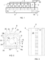
- FIG 1 is shown schematically a piston engine 1 together with an intake system and an exhaust system.
- the engine 1 is a large internal combustion engine, such as a main or an auxiliary engine of a ship.
- the rated power of the engine 1 is at least 150 kW per cylinder and the cylinder bore is at least 150 mm.
- the engine 1 comprises six cylinders 2, but the engine 1 could comprise any reasonable number of cylinders 2, such as 4 to 24 cylinders 2.
- the cylinders 2 are arranged in line, but the cylinders 2 could also be, for instance, in a V-configuration.
- the engine 1 is provided with a turbocharger 3 comprising a turbine 3a and a compressor 3b.
- the engine 1 could also be provided with two or more turbochargers 3.
- the turbochargers 3 could be arranged in series and/or in parallel.
- a V-engine could comprise one or two turbochargers for each bank of the engine.
- the turbine 3a of the turbocharger 3 forms part of the exhaust system of the engine 1
- the compressor 3b of the turbocharger 3 forms part of the intake system of the engine 1.
- From the compressor 3b of the turbocharger 3 the pressurized intake air is introduced into an intake duct 4, which conveys the intake air into the cylinders 2 of the engine 1.
- the exhaust system of the engine 1 comprises an exhaust gas receiver 5.
- the exhaust gas receiver 5 comprises a number of branches 5a. Each branch 5a of the exhaust gas receiver 5 is connected to a cylinder 2 of the engine 1 for receiving exhaust gases. The exhaust gas receiver 5 is connected to the turbine 3a of the turbocharger 3 for introducing the exhaust gases into the turbine 3a.
- the engine 1 is provided with a heat insulation arrangement that is arranged around the exhaust system of the engine 1.
- the heat insulation arrangement comprises a first heat insulation structure 6 that is arranged around the exhaust gas receiver 5 and a second heat insulation structure 7 that is arranged around the turbine 3a of the turbocharger 3.
- Figure 2 shows a cross-sectional view of the first heat insulation structure 6 and figure 3 shows a top view of the first heat insulation structure 6.
- the first heat insulation structure 6 is arranged around the exhaust gas receiver 5 such that an air space 8 is formed between the exhaust gas receiver 5 and the first heat insulation structure 6.
- the first heat insulation structure 6 comprises an outer shell layer 9, a middle shell layer 10 that is arranged inside the outer shell layer 9 and a first inner shell layer 11 that is arranged inside the middle shell layer 10.
- the middle shell layer 10 is at a distance from the outer shell layer 9 such that a first air gap 14 is formed between the outer shell layer 9 and the middle shell layer 10.
- the first inner shell layer 11 is at a distance from the middle shell layer 10 such that a first insulation layer 15 can be arranged between the middle shell layer 10 and the first inner shell layer 9.
- the first insulation layer 15 is made of non-liquid and non-gaseous insulation material.
- the insulation material can be, for instance, mineral wool, such as rock wool.
- the outer shell layer 9, the middle shell layer 10 and the first inner shell layer 11 can be made, for instance, of a sheet metal.
- the first air gap 14 is naturally ventilated. The ventilation is thus based on differences in the density of air, and no fans are needed for circulating air in the first air gap 14.
- the outer shell layer 9 is provided with venting apertures 18a, 18b, 19.
- Air inlets 18a are arranged in a lower part of the first heat insulation structure 6 and air outlets 19 are arranged in an upper part of the first heat insulation structure 6.
- Additional air inlets 18b are arranged in the side walls 21 of the outer shell layer 9. The additional inlets 18b are thus between the air outlets 19 and the air inlets 18a of the lower part of the first heat insulation structure 6. The air is introduced into the first air gap 14 via the air inlets 18a, 18b.
- the first heat insulation structure 6 comprises inclined sections 20, which connect the side walls 21 of the heat insulation structure 6 to the bottom 22 of the heat insulation structure 6.
- the air inlets 18 in the lower part of the first heat insulation structure 6 are arranged in the inclined sections 20 on both sides of the heat insulation structure 6.
- Each side of the first heat insulation structure 6 comprises a plurality of air inlets 18a, 18b, which are arranged along the construction.
- the air outlets 19 are arranged in a top plate 23 of the first heat insulation structure 6.
- the air outlets 19 are arranged at a distance from the longitudinal center line of the heat insulation arrangement.
- the heat insulation structure 6 of figure 2 comprises two rows of air outlets 19, one row being arranged on each side of the longitudinal center line of the heat insulation structure 6.
- the first heat insulation structure 6 is further provided with partition walls 24, which divide the first air gap 14 into compartments in the longitudinal direction of the heat insulation structure 6.
- the partition walls 24 are provided with apertures 25, which allow air flow between the compartments.
- both the air inlets 18a, 18b and the air outlets 19 are arranged at regular intervals along the longitudinal direction of the first heat insulation structure 6, the flow direction of the air within the first air gap 14 is mainly from the bottom of the first heat insulation structure 6 towards the top of the heat insulation structure 6. This helps to keep the surface temperature of the outer shell layer 9 steady.
- the first heat insulation structure 6 is further provided with a cover structure 26.
- the cover structure 26 is arranged above the outer shell layer 9 and covers the air outlets 19 of the outer shell layer 9. Also the cover structure 26 is provided with venting apertures 27, 28. Air outlets 27 are arranged on top of the cover structure 26.
- the air outlets 27 of the cover structure 26 are in a vertical direction above the air outlets 19 of the outer shell layer 9.
- the air outlets 27 of the cover structure 26 are arranged in a horizontal direction in such a way in relation to the air outlets 19 of the outer shell layer 9 that a labyrinth structure for the venting air is formed.
- the construction of the cover structure 26 enhances air flow through the first air gap 14 and also prevents fuel spillages on the surfaces at higher temperatures.
- Air inlets 28 are arranged on both sides of the cover structure 26.
- the air inlets 28 are below the air outlets 27 of the cover structure 26 in a vertical direction. Also the air inlets 28 of the cover structure 26 enhance air flow in the first heat insulation structure 6. In the embodiment of figure 2 , the air from the first air gap 14 is released into the air immediately around the first heat insulation structure 6.
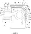
- FIG 4 is shown a cross-sectional view of a second heat insulation structure 7, which is arranged around a turbine 3a of a turbocharger 3.
- the second heat insulation structure 7 is connected to the first heat insulation structure 6.
- the construction of the second heat insulation structure 7 is similar to the construction of first heat insulation structure 6.
- the second heat insulation structure 7 is provided with additional layers.
- the second heat insulation structure 7 comprises an outer shell layer 9, a middle shell layer 10 that is arranged inside the outer shell layer 9 and a first inner shell layer 11 that is arranged inside the middle shell layer 10.
- the middle shell layer 10 is at a distance from the outer shell layer 9 such that a first air gap 14 is formed between the outer shell layer 9 and the middle shell layer 10.
- the first inner shell layer 11 is at a distance from the middle shell layer 10 such that a first insulation layer 15 can be arranged between the middle shell layer 10 and the first inner shell layer 9.
- the first insulation layer 15 is made of non-liquid and non-gaseous insulation material.
- the insulation material can be, for instance, mineral wool, such as rock wool.
- a second inner shell layer 12 is arranged inside the first inner shell layer 11 and a third inner shell layer 13 is arranged inside the second inner shell layer 12.
- the second inner shell layer 12 is at a distance from the first inner shell layer 11 and the third inner shell layer 13 is at a distance from the second inner shell layer 12.
- a second air gap 16 is formed between the first inner shell layer 11 and the second inner shell layer 12.
- a second insulation layer 17 is formed between the second inner shell layer 12 and the third inner shell layer 13.
- the insulation material used for the second insulation layer 17 can be the same as the material used for the first insulation layer 15.
- the outer shell layer 9, the middle shell layer 10 and the inner shell layers 11, 12, 13 can be made,
- the second heat insulation structure 7 does not encircle the turbine 3a of the turbocharger 3 completely. Since the turbocharger 3 is arranged on a turbocharger bracket 32, heat insulation below the turbine 3a does not need to be as effective as on the other sides of the turbine 3a. Below the turbine 3a, a single layer of insulation material may be sufficient. However, the second heat insulation structure 7 could encircle the turbine 3a of the turbocharger 3 on all sides. In the embodiment of figure 4 , the bottom of the outer shell layer 9 of the second heat insulation structure 7 is open. An air inlet 18 for introducing air into the first air gap 14 is thus formed in the bottom of the second heat insulation structure 7.
- air inlets could also be arranged in the side wall of the outer shell layer 9 in a lower part of the second heat insulation structure 7.
- the outer shell layer 9 is also provided with air outlets 19 in an upper part of the second heat insulation structure 7. Also the first air gap 14 of the second heat insulation structure 7 is naturally ventilated.
- the second heat insulation structure 7 further comprises a cover structure 31, which is arranged above the outer shell layer 9.
- the cover structure 31 covers the air outlets 19 of the outer shell layer 9. Contrary to the cover structure 26 of the first heat insulation structure 6, the cover structure 31 of the second heat insulation structure 7 is not provided with air inlets and air outlets. Instead, the cover structure 31 of the second heat insulation structure 7 is connected to a flow channel, which conveys the air away from the space between the outer shell layer 9 and the cover structure 31. The hot air is thus not released to the air in the proximity of the second heat insulation structure 7, but conveyed to a location where the air is not exposed to flammable fluids.
- the second air gap 16 is provided with at least one air inlet 30, which is arranged in the bottom of the second heat insulation structure 7.
- An upper part of the second air gap 16 is connected to a flow channel 29, through which air can be conveyed out of the second air gap 16.
- the second air gap 16 is naturally ventilated.
- the flow channel 29 is connected to the space between the outer shell layer 9 and the cover structure 31. The air from the second air gap 16 is thus mixed with the air from the first air gap 14 and conveyed away from the proximity of the heat insulation arrangement.
Landscapes
- Engineering & Computer Science (AREA)
- Chemical & Material Sciences (AREA)
- Combustion & Propulsion (AREA)
- Mechanical Engineering (AREA)
- General Engineering & Computer Science (AREA)
- Ocean & Marine Engineering (AREA)
- Supercharger (AREA)
- Exhaust Silencers (AREA)
- Thermal Insulation (AREA)
Description
- The present invention relates to a heat insulation structure for a component of an exhaust system of a piston engine as defined in
claim 1. - Many different treaties, such as the International Convention for the Safety of Life at Sea (SOLAS), set minimum safety standards for the construction, equipment and operation of ships. Many of the standards concern the construction of the engines used in the ships. The requirements set by the major treaties can be fulfilled with conventional constructions, but in some cases the use or the operating conditions of a ship set requirements that are much more difficult to meet. One aspect that is regulated by SOLAS and concerns engines is the surface temperature of the exhaust system. The requirements of SOLAS can be met by a single insulation layer arranged around an exhaust gas receiver and a turbocharger, but in some cases much lower surface temperatures need to be achieved (see
GB2045859A DE2037135A1 ). - An object of the present invention is to provide an improved heat insulation structure for a component of an exhaust system of a piston engine. The characterizing features of the heat insulation structure according to the invention are given in
claim 1. - The heat insulation structure according to the invention is arrangeable around a component of an exhaust system in such a manner that an air space is formed between the component and the heat insulation structure and comprises an outer shell layer, a middle shell layer that is arranged inside the outer shell layer, and a first inner shell layer that is arranged inside the middle shell layer, wherein a first air gap is arranged between the outer shell layer and the middle shell layer, a first insulation layer of insulation material is arranged between the middle shell layer and the first inner shell layer, and the outer shell layer is provided with venting apertures for natural ventilation of the first air gap.
- With the heat insulation structure according to the invention, the surface temperatures of the heat insulation structure are significantly reduced compared to conventional heat insulation structures used in the exhaust systems of piston engines. Low surface temperature can be achieved without fans or additional insulation layers outside the outer shell layer.
- According to an embodiment of the invention, a lower part of the outer shell layer is provided with at least one air inlet for introducing venting air into the first air gap. Air inlets in the lower part and air outlets in the upper part of the outer shell layer create an effective venting air flow through the first air gap keeping the surface temperature of the outer shell layer low.
- According to an embodiment of the invention, the outer shell layer is provided with additional air inlets between the air inlets of the lower part and the air outlets. The additional air inlets enhance the ventilation of the first air gap.
- The cover structure prevents fuel spillages on surfaces at higher temperatures.
- Due to the air outlets of the cover structure, the venting air can be released into the air immediately around the heat insulation structure. The location of the air outlets of the cover structure above the air outlets of the outer shell layer ensures that air flow through the first air gap is generated.
- According to an embodiment of the invention, the air outlets of the cover structure are arranged in a horizontal direction in relation to the air outlets of the outer shell layer such that a labyrinth structure for the venting air is formed. The labyrinth structure generates better air flow through the first air gap. It also ensures that possible fuel spillages on the cover structure do not reach directly the hotter surfaces inside the heat insulation structure via the air outlets.
- The air inlets of the cover structure improve air flow in the heat insulation structure.
- According to an embodiment of the invention, the heat insulation structure further comprises a second inner shell layer that is arranged inside the first inner shell layer, a third inner shell layer that is arranged inside the second inner shell layer, a second air gap that is arranged between the first inner shell layer and the second inner shell layer, and a second insulation layer of insulation material that is arranged between the second inner shell layer and the third inner shell layer. The further air gap and insulation layer improve the heat insulation. This heat insulation structure is suitable in particular for a turbine of a turbocharger. If the engine is provided with two-stage turbocharging, especially the high-pressure turbocharger may need an improved heat insulation structure with two air gaps and insulation layers.
- According to an embodiment of the invention, the second air gap is provided with at least one air inlet for introducing air into the second air gap and connected to a flow channel that is arranged to convey air away from the second air gap. The temperature in the second air gap may be high, and therefore the air is preferably conveyed from the second air gap to a location, which is not exposed to possible sprays of flammable fluids.
- The insulation material can be for example mineral wool, such as rock wool.
- An exhaust system according to the invention comprises a heat insulation structure defined above arranged around a component of the exhaust system.
- The component of the exhaust system can be an exhaust gas receiver or a turbine of a turbocharger.
- A piston engine according to the invention comprises an exhaust system and a heat insulation structure defined above.
- Embodiments of the invention are described below in more detail with reference to the accompanying drawings, in which
-
Fig. 1 shows schematically a piston engine and an exhaust system, -
Fig. 2 shows a simplified cross-sectional view of a heat insulation structure for an exhaust gas receiver, -
Fig. 3 shows a top view of the heat insulation structure ofFig. 2 , and -
Fig. 4 shows a cross-sectional view of a heat insulation structure for a turbine of a turbocharger. - In
figure 1 is shown schematically apiston engine 1 together with an intake system and an exhaust system. Theengine 1 is a large internal combustion engine, such as a main or an auxiliary engine of a ship. The rated power of theengine 1 is at least 150 kW per cylinder and the cylinder bore is at least 150 mm. In the embodiment offigure 1 , theengine 1 comprises sixcylinders 2, but theengine 1 could comprise any reasonable number ofcylinders 2, such as 4 to 24cylinders 2. In the embodiment offigure 1 , thecylinders 2 are arranged in line, but thecylinders 2 could also be, for instance, in a V-configuration. - The
engine 1 is provided with aturbocharger 3 comprising aturbine 3a and acompressor 3b. Theengine 1 could also be provided with two ormore turbochargers 3. Theturbochargers 3 could be arranged in series and/or in parallel. For instance, a V-engine could comprise one or two turbochargers for each bank of the engine. Theturbine 3a of theturbocharger 3 forms part of the exhaust system of theengine 1, and thecompressor 3b of theturbocharger 3 forms part of the intake system of theengine 1. From thecompressor 3b of theturbocharger 3 the pressurized intake air is introduced into anintake duct 4, which conveys the intake air into thecylinders 2 of theengine 1. The exhaust system of theengine 1 comprises anexhaust gas receiver 5. Theexhaust gas receiver 5 comprises a number ofbranches 5a. Eachbranch 5a of theexhaust gas receiver 5 is connected to acylinder 2 of theengine 1 for receiving exhaust gases. Theexhaust gas receiver 5 is connected to theturbine 3a of theturbocharger 3 for introducing the exhaust gases into theturbine 3a. - Because of the high temperature of the exhaust gases, the
engine 1 is provided with a heat insulation arrangement that is arranged around the exhaust system of theengine 1. The heat insulation arrangement comprises a firstheat insulation structure 6 that is arranged around theexhaust gas receiver 5 and a secondheat insulation structure 7 that is arranged around theturbine 3a of theturbocharger 3. -
Figure 2 shows a cross-sectional view of the firstheat insulation structure 6 andfigure 3 shows a top view of the firstheat insulation structure 6. The firstheat insulation structure 6 is arranged around theexhaust gas receiver 5 such that anair space 8 is formed between theexhaust gas receiver 5 and the firstheat insulation structure 6. The firstheat insulation structure 6 comprises anouter shell layer 9, amiddle shell layer 10 that is arranged inside theouter shell layer 9 and a firstinner shell layer 11 that is arranged inside themiddle shell layer 10. Themiddle shell layer 10 is at a distance from theouter shell layer 9 such that afirst air gap 14 is formed between theouter shell layer 9 and themiddle shell layer 10. The firstinner shell layer 11 is at a distance from themiddle shell layer 10 such that afirst insulation layer 15 can be arranged between themiddle shell layer 10 and the firstinner shell layer 9. Thefirst insulation layer 15 is made of non-liquid and non-gaseous insulation material. The insulation material can be, for instance, mineral wool, such as rock wool. Theouter shell layer 9, themiddle shell layer 10 and the firstinner shell layer 11 can be made, for instance, of a sheet metal. - The
first air gap 14 is naturally ventilated. The ventilation is thus based on differences in the density of air, and no fans are needed for circulating air in thefirst air gap 14. For the ventilation of thefirst air gap 14, theouter shell layer 9 is provided with ventingapertures Air inlets 18a are arranged in a lower part of the firstheat insulation structure 6 andair outlets 19 are arranged in an upper part of the firstheat insulation structure 6.Additional air inlets 18b are arranged in theside walls 21 of theouter shell layer 9. Theadditional inlets 18b are thus between theair outlets 19 and theair inlets 18a of the lower part of the firstheat insulation structure 6. The air is introduced into thefirst air gap 14 via theair inlets heat insulation structure 6. In the embodiment offigure 2 , the firstheat insulation structure 6 comprisesinclined sections 20, which connect theside walls 21 of theheat insulation structure 6 to the bottom 22 of theheat insulation structure 6. The air inlets 18 in the lower part of the firstheat insulation structure 6 are arranged in theinclined sections 20 on both sides of theheat insulation structure 6. Each side of the firstheat insulation structure 6 comprises a plurality ofair inlets - In the embodiment of
figure 2 , theair outlets 19 are arranged in atop plate 23 of the firstheat insulation structure 6. Theair outlets 19 are arranged at a distance from the longitudinal center line of the heat insulation arrangement. Theheat insulation structure 6 offigure 2 comprises two rows ofair outlets 19, one row being arranged on each side of the longitudinal center line of theheat insulation structure 6. The firstheat insulation structure 6 is further provided withpartition walls 24, which divide thefirst air gap 14 into compartments in the longitudinal direction of theheat insulation structure 6. Thepartition walls 24 are provided withapertures 25, which allow air flow between the compartments. However, because both theair inlets air outlets 19 are arranged at regular intervals along the longitudinal direction of the firstheat insulation structure 6, the flow direction of the air within thefirst air gap 14 is mainly from the bottom of the firstheat insulation structure 6 towards the top of theheat insulation structure 6. This helps to keep the surface temperature of theouter shell layer 9 steady. - The first
heat insulation structure 6 is further provided with acover structure 26. Thecover structure 26 is arranged above theouter shell layer 9 and covers theair outlets 19 of theouter shell layer 9. Also thecover structure 26 is provided with ventingapertures Air outlets 27 are arranged on top of thecover structure 26. Theair outlets 27 of thecover structure 26 are in a vertical direction above theair outlets 19 of theouter shell layer 9. Theair outlets 27 of thecover structure 26 are arranged in a horizontal direction in such a way in relation to theair outlets 19 of theouter shell layer 9 that a labyrinth structure for the venting air is formed. The construction of thecover structure 26 enhances air flow through thefirst air gap 14 and also prevents fuel spillages on the surfaces at higher temperatures.Air inlets 28 are arranged on both sides of thecover structure 26. The air inlets 28 are below theair outlets 27 of thecover structure 26 in a vertical direction. Also theair inlets 28 of thecover structure 26 enhance air flow in the firstheat insulation structure 6. In the embodiment offigure 2 , the air from thefirst air gap 14 is released into the air immediately around the firstheat insulation structure 6. - In
figure 4 is shown a cross-sectional view of a secondheat insulation structure 7, which is arranged around aturbine 3a of aturbocharger 3. The secondheat insulation structure 7 is connected to the firstheat insulation structure 6. The construction of the secondheat insulation structure 7 is similar to the construction of firstheat insulation structure 6. However, due to the high temperature in theturbine 3a of theturbocharger 3, the secondheat insulation structure 7 is provided with additional layers. Also the secondheat insulation structure 7 comprises anouter shell layer 9, amiddle shell layer 10 that is arranged inside theouter shell layer 9 and a firstinner shell layer 11 that is arranged inside themiddle shell layer 10. Themiddle shell layer 10 is at a distance from theouter shell layer 9 such that afirst air gap 14 is formed between theouter shell layer 9 and themiddle shell layer 10. The firstinner shell layer 11 is at a distance from themiddle shell layer 10 such that afirst insulation layer 15 can be arranged between themiddle shell layer 10 and the firstinner shell layer 9. Thefirst insulation layer 15 is made of non-liquid and non-gaseous insulation material. The insulation material can be, for instance, mineral wool, such as rock wool. A secondinner shell layer 12 is arranged inside the firstinner shell layer 11 and a thirdinner shell layer 13 is arranged inside the secondinner shell layer 12. The secondinner shell layer 12 is at a distance from the firstinner shell layer 11 and the thirdinner shell layer 13 is at a distance from the secondinner shell layer 12. Asecond air gap 16 is formed between the firstinner shell layer 11 and the secondinner shell layer 12. Asecond insulation layer 17 is formed between the secondinner shell layer 12 and the thirdinner shell layer 13. The insulation material used for thesecond insulation layer 17 can be the same as the material used for thefirst insulation layer 15. Theouter shell layer 9, themiddle shell layer 10 and the inner shell layers 11, 12, 13 can be made, for instance, of a sheet metal. - In the embodiment of
figure 4 , the secondheat insulation structure 7 does not encircle theturbine 3a of theturbocharger 3 completely. Since theturbocharger 3 is arranged on aturbocharger bracket 32, heat insulation below theturbine 3a does not need to be as effective as on the other sides of theturbine 3a. Below theturbine 3a, a single layer of insulation material may be sufficient. However, the secondheat insulation structure 7 could encircle theturbine 3a of theturbocharger 3 on all sides. In the embodiment offigure 4 , the bottom of theouter shell layer 9 of the secondheat insulation structure 7 is open. Anair inlet 18 for introducing air into thefirst air gap 14 is thus formed in the bottom of the secondheat insulation structure 7. Instead of or in addition to theair inlet 18 in the bottom of the secondheat insulation structure 7, air inlets could also be arranged in the side wall of theouter shell layer 9 in a lower part of the secondheat insulation structure 7. Theouter shell layer 9 is also provided withair outlets 19 in an upper part of the secondheat insulation structure 7. Also thefirst air gap 14 of the secondheat insulation structure 7 is naturally ventilated. - The second
heat insulation structure 7 further comprises acover structure 31, which is arranged above theouter shell layer 9. Thecover structure 31 covers theair outlets 19 of theouter shell layer 9. Contrary to thecover structure 26 of the firstheat insulation structure 6, thecover structure 31 of the secondheat insulation structure 7 is not provided with air inlets and air outlets. Instead, thecover structure 31 of the secondheat insulation structure 7 is connected to a flow channel, which conveys the air away from the space between theouter shell layer 9 and thecover structure 31. The hot air is thus not released to the air in the proximity of the secondheat insulation structure 7, but conveyed to a location where the air is not exposed to flammable fluids. - Also the
second air gap 16 is provided with at least oneair inlet 30, which is arranged in the bottom of the secondheat insulation structure 7. An upper part of thesecond air gap 16 is connected to aflow channel 29, through which air can be conveyed out of thesecond air gap 16. Also thesecond air gap 16 is naturally ventilated. Theflow channel 29 is connected to the space between theouter shell layer 9 and thecover structure 31. The air from thesecond air gap 16 is thus mixed with the air from thefirst air gap 14 and conveyed away from the proximity of the heat insulation arrangement. - It will be appreciated by a person skilled in the art that the invention is not limited to the embodiments described above, but may vary within the scope of the appended claims.
Claims (11)
- A heat insulation structure (6, 7) for a component (3a, 5) of an exhaust system of a piston engine (1), the heat insulation structure (6, 7) being arrangeable around the component (3a, 5) of the exhaust system in such a manner that an air space (8) is formed between the component (3a, 5) and the heat insulation structure (6, 7), the heat insulation structure (6, 7) comprising- an outer shell layer (9),- a middle shell layer (10) that is arranged inside the outer shell layer (9), and- a first inner shell layer (11) that is arranged inside the middle shell layer (10),wherein- a first air gap (14) is arranged between the outer shell layer (9) and the middle shell layer (10),- a first insulation layer (15) of insulation material is arranged between the middle shell layer (10) and the first inner shell layer (11),- the outer shell layer (9) is provided with venting apertures (18, 18a, 18b, 19) for natural ventilation of the first air gap (14),- the venting apertures (18, 18a, 18b, 19) comprise air outlets (19), which are arranged in an upper part of the outer shell layer (9) for releasing venting air from the first air gap (14),- a cover structure (26) that is provided with venting apertures (27, 28) is arranged above the outer shell layer (9) to cover the air outlets (19) of the outer shell layer (9),- the venting apertures (27, 28) of the cover structure (26) comprise air outlets (27), which are arranged in a vertical direction above the air outlets (19) of the outer shell layer (9),characterized in that the venting apertures (27, 28) of the cover structure (26) comprise air inlets (28), which are arranged in a vertical direction below the air outlets (27) of the cover structure (26).
- A heat insulation structure (6, 7) according to claim 1, wherein the venting apertures (18, 18a, 18b, 19) of the outer shell layer (9) comprise at least one air inlet (18, 18a), which is arranged in a lower part of the outer shell layer (9) for introducing venting air into the first air gap (14).
- A heat insulation structure (6, 7) according to claim 2, wherein the venting apertures (18, 18a, 18b, 19) of the outer shell layer (9) comprise additional air inlets (18b) between the air inlets (18a) of the lower part and the air outlets (19).
- A heat insulation structure (6, 7) according to any of claims 1-3, wherein the air outlets (27) of the cover structure (26) are arranged in a horizontal direction in relation to the air outlets (19) of the outer shell layer (9) such that a labyrinth structure for the venting air is formed.
- A heat insulation structure (6, 7) according to any of the preceding claims, wherein the heat insulation structure (6, 7) further comprises- a second inner shell layer (12) that is arranged inside the first inner shell layer (11),- a third inner shell layer (13) that is arranged inside the second inner shell layer (12),- a second air gap (16) that is arranged between the first inner shell layer (11) and the second inner shell layer (12), and- a second insulation layer (17) of insulation material that is arranged between the second inner shell layer (12) and the third inner shell layer (13).
- A heat insulation structure (6, 7) according to claim 5, wherein the second air gap (16) is provided with at least one air inlet (30) for introducing air into the second air gap (16) and connected to a flow channel (29) that is arranged to convey air away from the second air gap (16).
- A heat insulation structure (6, 7) according to any of the preceding claims, wherein the insulation material is mineral wool, such as rock wool.
- An exhaust system for a piston engine (1), wherein the exhaust system comprises a heat insulation structure (6, 7) according to any of the preceding claims arranged around a component (3a, 5) of the exhaust system.
- An exhaust system according to claim 8, wherein the component (3a, 5) of the exhaust system is an exhaust gas receiver (5).
- An exhaust system according to claim 8, wherein the component (3a, 5) of the exhaust system is a turbine (3a) of a turbocharger (3).
- A piston engine (1) comprising an exhaust system and a heat insulation structure (6, 7) according to any of claims 1 to 7.
Applications Claiming Priority (1)
| Application Number | Priority Date | Filing Date | Title |
|---|---|---|---|
| PCT/FI2015/050801 WO2017085353A1 (en) | 2015-11-18 | 2015-11-18 | Heat insulation structure |
Publications (2)
| Publication Number | Publication Date |
|---|---|
| EP3390790A1 EP3390790A1 (en) | 2018-10-24 |
| EP3390790B1 true EP3390790B1 (en) | 2019-09-04 |
Family
ID=54707809
Family Applications (1)
| Application Number | Title | Priority Date | Filing Date |
|---|---|---|---|
| EP15801891.1A Active EP3390790B1 (en) | 2015-11-18 | 2015-11-18 | Heat insulation structure |
Country Status (6)
| Country | Link |
|---|---|
| US (1) | US10519844B2 (en) |
| EP (1) | EP3390790B1 (en) |
| JP (1) | JP6592198B2 (en) |
| KR (1) | KR101967594B1 (en) |
| CN (1) | CN108368768B (en) |
| WO (1) | WO2017085353A1 (en) |
Families Citing this family (6)
| Publication number | Priority date | Publication date | Assignee | Title |
|---|---|---|---|---|
| US10605147B2 (en) * | 2015-10-12 | 2020-03-31 | Angelo Miretti | Engine with explosion protection |
| WO2017098452A1 (en) * | 2015-12-11 | 2017-06-15 | Pj Aucamp | Cooling system for emission gases of an electronically controlled engine |
| US10746081B2 (en) | 2018-08-14 | 2020-08-18 | Caterpillar Inc. | Exhaust component enclosure system |
| JP7349899B2 (en) * | 2019-12-23 | 2023-09-25 | 住友重機械マリンエンジニアリング株式会社 | Thermal insulation structure of exhaust gas treatment section |
| KR102461551B1 (en) | 2021-01-05 | 2022-11-01 | 주식회사 레가토 | Cooking piate coupling structure of electric cooker |
| FI130433B (en) | 2021-07-30 | 2023-08-30 | Adiabatix Oy | Cooling arrangement |
Family Cites Families (10)
| Publication number | Priority date | Publication date | Assignee | Title |
|---|---|---|---|---|
| DD80714A1 (en) * | 1970-03-03 | 1971-03-20 | Exhaust pipe for supercharged internal combustion engines | |
| FR2314844A1 (en) * | 1975-06-17 | 1977-01-14 | Luchaire Sa | CAR BUMPER SYSTEM |
| DE2908878A1 (en) * | 1979-03-07 | 1980-09-18 | Kloeckner Humboldt Deutz Ag | EXHAUST SYSTEM FOR A MULTI-CYLINDER PISTON PISTON COMBUSTION ENGINE |
| JPH09177550A (en) * | 1995-12-25 | 1997-07-08 | Mitsubishi Motors Corp | Vertical exhaust system for vehicles |
| EP1426557B1 (en) | 2002-12-03 | 2013-07-17 | BorgWarner, Inc. | Casing for turbo charger |
| JP5020185B2 (en) * | 2008-07-28 | 2012-09-05 | 三菱ふそうトラック・バス株式会社 | Exhaust purification device |
| DE102008035562A1 (en) * | 2008-07-30 | 2010-02-04 | Emitec Gesellschaft Für Emissionstechnologie Mbh | Emission control system for diesel engines of commercial vehicles |
| US10508583B2 (en) * | 2012-08-30 | 2019-12-17 | Bosal Emission Control Systems Nv | Composite exhaust element |
| DE202012010993U1 (en) * | 2012-11-16 | 2013-11-20 | Reinz-Dichtungs-Gmbh | heat shield |
| CN203962161U (en) * | 2013-12-25 | 2014-11-26 | 比亚迪股份有限公司 | A kind of engine heat shield |
-
2015
- 2015-11-18 JP JP2018524772A patent/JP6592198B2/en active Active
- 2015-11-18 CN CN201580084676.6A patent/CN108368768B/en active Active
- 2015-11-18 WO PCT/FI2015/050801 patent/WO2017085353A1/en not_active Ceased
- 2015-11-18 KR KR1020187015673A patent/KR101967594B1/en active Active
- 2015-11-18 US US15/775,225 patent/US10519844B2/en active Active
- 2015-11-18 EP EP15801891.1A patent/EP3390790B1/en active Active
Non-Patent Citations (1)
| Title |
|---|
| None * |
Also Published As
| Publication number | Publication date |
|---|---|
| JP6592198B2 (en) | 2019-10-16 |
| JP2019500535A (en) | 2019-01-10 |
| WO2017085353A1 (en) | 2017-05-26 |
| US10519844B2 (en) | 2019-12-31 |
| CN108368768A (en) | 2018-08-03 |
| KR101967594B1 (en) | 2019-04-09 |
| EP3390790A1 (en) | 2018-10-24 |
| KR20180081541A (en) | 2018-07-16 |
| CN108368768B (en) | 2020-02-21 |
| US20180328254A1 (en) | 2018-11-15 |
Similar Documents
| Publication | Publication Date | Title |
|---|---|---|
| US10519844B2 (en) | Heat insulation structure | |
| US9133730B2 (en) | Exhaust turbocharger | |
| US9133745B2 (en) | Split/dual plane integrated exhaust manifold for dual scroll turbo charger | |
| JP2013151906A (en) | Freezing prevention structure for pcv passage, and intake manifold | |
| CN103867276A (en) | Dual muffler | |
| WO2005091902A3 (en) | Highly insulated exhaust manifold | |
| KR101951970B1 (en) | Multipurpose Air Cooler Casing Assembly for Twin Turbocharger | |
| KR101918878B1 (en) | Combustor and gas turbine | |
| EP3715598B1 (en) | Exhaust pipe assembly and engine | |
| KR102629283B1 (en) | Multi-engine plant | |
| US1816371A (en) | Ship propelled by internal combustion engine | |
| Mihai et al. | Ventilation of engine rooms in diesel engines ships | |
| CN104271907B (en) | Radiant heat discharge device | |
| US8307857B2 (en) | Insulation assembly for use with an auxiliary power unit having an exhaust muffler | |
| FI124964B (en) | Exhaust module and piston engine | |
| EP2612005B1 (en) | Exhaust module and internal combustion engine | |
| JP4176788B2 (en) | Exhaust gas receiver for large two-cycle diesel engines | |
| US20140208726A1 (en) | Air Shielded Water Cooled Exhaust Manifold With Exhaust Tube Support | |
| EP2955100B1 (en) | A duct arrangement for an internal combustion engine | |
| EP2746559B1 (en) | Cylinder head and engine block configuration | |
| KR20160026406A (en) | Air chamber moudle integrated double wall exhaust passage as one body | |
| KR101478451B1 (en) | Exhaust structure of ship | |
| EP3635239B1 (en) | Fluid distribution element | |
| KR20160098599A (en) | Cylinder head used in ship engine and DF Engine with pathway of cooling water | |
| US20170037781A1 (en) | Inlet system for a gas turbine |
Legal Events
| Date | Code | Title | Description |
|---|---|---|---|
| STAA | Information on the status of an ep patent application or granted ep patent |
Free format text: STATUS: THE INTERNATIONAL PUBLICATION HAS BEEN MADE |
|
| PUAI | Public reference made under article 153(3) epc to a published international application that has entered the european phase |
Free format text: ORIGINAL CODE: 0009012 |
|
| STAA | Information on the status of an ep patent application or granted ep patent |
Free format text: STATUS: REQUEST FOR EXAMINATION WAS MADE |
|
| 17P | Request for examination filed |
Effective date: 20180619 |
|
| AK | Designated contracting states |
Kind code of ref document: A1 Designated state(s): AL AT BE BG CH CY CZ DE DK EE ES FI FR GB GR HR HU IE IS IT LI LT LU LV MC MK MT NL NO PL PT RO RS SE SI SK SM TR |
|
| AX | Request for extension of the european patent |
Extension state: BA ME |
|
| DAV | Request for validation of the european patent (deleted) | ||
| DAX | Request for extension of the european patent (deleted) | ||
| GRAP | Despatch of communication of intention to grant a patent |
Free format text: ORIGINAL CODE: EPIDOSNIGR1 |
|
| STAA | Information on the status of an ep patent application or granted ep patent |
Free format text: STATUS: GRANT OF PATENT IS INTENDED |
|
| INTG | Intention to grant announced |
Effective date: 20190521 |
|
| GRAS | Grant fee paid |
Free format text: ORIGINAL CODE: EPIDOSNIGR3 |
|
| GRAA | (expected) grant |
Free format text: ORIGINAL CODE: 0009210 |
|
| STAA | Information on the status of an ep patent application or granted ep patent |
Free format text: STATUS: THE PATENT HAS BEEN GRANTED |
|
| AK | Designated contracting states |
Kind code of ref document: B1 Designated state(s): AL AT BE BG CH CY CZ DE DK EE ES FI FR GB GR HR HU IE IS IT LI LT LU LV MC MK MT NL NO PL PT RO RS SE SI SK SM TR |
|
| REG | Reference to a national code |
Ref country code: GB Ref legal event code: FG4D |
|
| REG | Reference to a national code |
Ref country code: CH Ref legal event code: EP |
|
| REG | Reference to a national code |
Ref country code: AT Ref legal event code: REF Ref document number: 1175641 Country of ref document: AT Kind code of ref document: T Effective date: 20190915 |
|
| REG | Reference to a national code |
Ref country code: DE Ref legal event code: R096 Ref document number: 602015037324 Country of ref document: DE Ref country code: IE Ref legal event code: FG4D |
|
| REG | Reference to a national code |
Ref country code: NL Ref legal event code: MP Effective date: 20190904 |
|
| REG | Reference to a national code |
Ref country code: LT Ref legal event code: MG4D |
|
| PG25 | Lapsed in a contracting state [announced via postgrant information from national office to epo] |
Ref country code: LT Free format text: LAPSE BECAUSE OF FAILURE TO SUBMIT A TRANSLATION OF THE DESCRIPTION OR TO PAY THE FEE WITHIN THE PRESCRIBED TIME-LIMIT Effective date: 20190904 Ref country code: HR Free format text: LAPSE BECAUSE OF FAILURE TO SUBMIT A TRANSLATION OF THE DESCRIPTION OR TO PAY THE FEE WITHIN THE PRESCRIBED TIME-LIMIT Effective date: 20190904 Ref country code: FI Free format text: LAPSE BECAUSE OF FAILURE TO SUBMIT A TRANSLATION OF THE DESCRIPTION OR TO PAY THE FEE WITHIN THE PRESCRIBED TIME-LIMIT Effective date: 20190904 Ref country code: SE Free format text: LAPSE BECAUSE OF FAILURE TO SUBMIT A TRANSLATION OF THE DESCRIPTION OR TO PAY THE FEE WITHIN THE PRESCRIBED TIME-LIMIT Effective date: 20190904 Ref country code: NO Free format text: LAPSE BECAUSE OF FAILURE TO SUBMIT A TRANSLATION OF THE DESCRIPTION OR TO PAY THE FEE WITHIN THE PRESCRIBED TIME-LIMIT Effective date: 20191204 Ref country code: BG Free format text: LAPSE BECAUSE OF FAILURE TO SUBMIT A TRANSLATION OF THE DESCRIPTION OR TO PAY THE FEE WITHIN THE PRESCRIBED TIME-LIMIT Effective date: 20191204 |
|
| PG25 | Lapsed in a contracting state [announced via postgrant information from national office to epo] |
Ref country code: RS Free format text: LAPSE BECAUSE OF FAILURE TO SUBMIT A TRANSLATION OF THE DESCRIPTION OR TO PAY THE FEE WITHIN THE PRESCRIBED TIME-LIMIT Effective date: 20190904 Ref country code: LV Free format text: LAPSE BECAUSE OF FAILURE TO SUBMIT A TRANSLATION OF THE DESCRIPTION OR TO PAY THE FEE WITHIN THE PRESCRIBED TIME-LIMIT Effective date: 20190904 Ref country code: ES Free format text: LAPSE BECAUSE OF FAILURE TO SUBMIT A TRANSLATION OF THE DESCRIPTION OR TO PAY THE FEE WITHIN THE PRESCRIBED TIME-LIMIT Effective date: 20190904 Ref country code: AL Free format text: LAPSE BECAUSE OF FAILURE TO SUBMIT A TRANSLATION OF THE DESCRIPTION OR TO PAY THE FEE WITHIN THE PRESCRIBED TIME-LIMIT Effective date: 20190904 Ref country code: GR Free format text: LAPSE BECAUSE OF FAILURE TO SUBMIT A TRANSLATION OF THE DESCRIPTION OR TO PAY THE FEE WITHIN THE PRESCRIBED TIME-LIMIT Effective date: 20191205 |
|
| PG25 | Lapsed in a contracting state [announced via postgrant information from national office to epo] |
Ref country code: NL Free format text: LAPSE BECAUSE OF FAILURE TO SUBMIT A TRANSLATION OF THE DESCRIPTION OR TO PAY THE FEE WITHIN THE PRESCRIBED TIME-LIMIT Effective date: 20190904 Ref country code: PT Free format text: LAPSE BECAUSE OF FAILURE TO SUBMIT A TRANSLATION OF THE DESCRIPTION OR TO PAY THE FEE WITHIN THE PRESCRIBED TIME-LIMIT Effective date: 20200106 Ref country code: PL Free format text: LAPSE BECAUSE OF FAILURE TO SUBMIT A TRANSLATION OF THE DESCRIPTION OR TO PAY THE FEE WITHIN THE PRESCRIBED TIME-LIMIT Effective date: 20190904 Ref country code: RO Free format text: LAPSE BECAUSE OF FAILURE TO SUBMIT A TRANSLATION OF THE DESCRIPTION OR TO PAY THE FEE WITHIN THE PRESCRIBED TIME-LIMIT Effective date: 20190904 Ref country code: EE Free format text: LAPSE BECAUSE OF FAILURE TO SUBMIT A TRANSLATION OF THE DESCRIPTION OR TO PAY THE FEE WITHIN THE PRESCRIBED TIME-LIMIT Effective date: 20190904 |
|
| PG25 | Lapsed in a contracting state [announced via postgrant information from national office to epo] |
Ref country code: IS Free format text: LAPSE BECAUSE OF FAILURE TO SUBMIT A TRANSLATION OF THE DESCRIPTION OR TO PAY THE FEE WITHIN THE PRESCRIBED TIME-LIMIT Effective date: 20200224 Ref country code: SM Free format text: LAPSE BECAUSE OF FAILURE TO SUBMIT A TRANSLATION OF THE DESCRIPTION OR TO PAY THE FEE WITHIN THE PRESCRIBED TIME-LIMIT Effective date: 20190904 Ref country code: CZ Free format text: LAPSE BECAUSE OF FAILURE TO SUBMIT A TRANSLATION OF THE DESCRIPTION OR TO PAY THE FEE WITHIN THE PRESCRIBED TIME-LIMIT Effective date: 20190904 Ref country code: SK Free format text: LAPSE BECAUSE OF FAILURE TO SUBMIT A TRANSLATION OF THE DESCRIPTION OR TO PAY THE FEE WITHIN THE PRESCRIBED TIME-LIMIT Effective date: 20190904 |
|
| REG | Reference to a national code |
Ref country code: DE Ref legal event code: R097 Ref document number: 602015037324 Country of ref document: DE |
|
| REG | Reference to a national code |
Ref country code: CH Ref legal event code: PL |
|
| PLBE | No opposition filed within time limit |
Free format text: ORIGINAL CODE: 0009261 |
|
| STAA | Information on the status of an ep patent application or granted ep patent |
Free format text: STATUS: NO OPPOSITION FILED WITHIN TIME LIMIT |
|
| PG2D | Information on lapse in contracting state deleted |
Ref country code: IS |
|
| PG25 | Lapsed in a contracting state [announced via postgrant information from national office to epo] |
Ref country code: CH Free format text: LAPSE BECAUSE OF NON-PAYMENT OF DUE FEES Effective date: 20191130 Ref country code: MC Free format text: LAPSE BECAUSE OF FAILURE TO SUBMIT A TRANSLATION OF THE DESCRIPTION OR TO PAY THE FEE WITHIN THE PRESCRIBED TIME-LIMIT Effective date: 20190904 Ref country code: DK Free format text: LAPSE BECAUSE OF FAILURE TO SUBMIT A TRANSLATION OF THE DESCRIPTION OR TO PAY THE FEE WITHIN THE PRESCRIBED TIME-LIMIT Effective date: 20190904 Ref country code: LI Free format text: LAPSE BECAUSE OF NON-PAYMENT OF DUE FEES Effective date: 20191130 Ref country code: LU Free format text: LAPSE BECAUSE OF NON-PAYMENT OF DUE FEES Effective date: 20191118 Ref country code: IS Free format text: LAPSE BECAUSE OF FAILURE TO SUBMIT A TRANSLATION OF THE DESCRIPTION OR TO PAY THE FEE WITHIN THE PRESCRIBED TIME-LIMIT Effective date: 20200105 |
|
| 26N | No opposition filed |
Effective date: 20200605 |
|
| REG | Reference to a national code |
Ref country code: BE Ref legal event code: MM Effective date: 20191130 |
|
| PG25 | Lapsed in a contracting state [announced via postgrant information from national office to epo] |
Ref country code: FR Free format text: LAPSE BECAUSE OF NON-PAYMENT OF DUE FEES Effective date: 20191130 Ref country code: IE Free format text: LAPSE BECAUSE OF NON-PAYMENT OF DUE FEES Effective date: 20191118 |
|
| PG25 | Lapsed in a contracting state [announced via postgrant information from national office to epo] |
Ref country code: BE Free format text: LAPSE BECAUSE OF NON-PAYMENT OF DUE FEES Effective date: 20191130 |
|
| PG25 | Lapsed in a contracting state [announced via postgrant information from national office to epo] |
Ref country code: CY Free format text: LAPSE BECAUSE OF FAILURE TO SUBMIT A TRANSLATION OF THE DESCRIPTION OR TO PAY THE FEE WITHIN THE PRESCRIBED TIME-LIMIT Effective date: 20190904 |
|
| PG25 | Lapsed in a contracting state [announced via postgrant information from national office to epo] |
Ref country code: HU Free format text: LAPSE BECAUSE OF FAILURE TO SUBMIT A TRANSLATION OF THE DESCRIPTION OR TO PAY THE FEE WITHIN THE PRESCRIBED TIME-LIMIT; INVALID AB INITIO Effective date: 20151118 Ref country code: MT Free format text: LAPSE BECAUSE OF FAILURE TO SUBMIT A TRANSLATION OF THE DESCRIPTION OR TO PAY THE FEE WITHIN THE PRESCRIBED TIME-LIMIT Effective date: 20190904 |
|
| PG25 | Lapsed in a contracting state [announced via postgrant information from national office to epo] |
Ref country code: SI Free format text: LAPSE BECAUSE OF FAILURE TO SUBMIT A TRANSLATION OF THE DESCRIPTION OR TO PAY THE FEE WITHIN THE PRESCRIBED TIME-LIMIT Effective date: 20190904 |
|
| REG | Reference to a national code |
Ref country code: AT Ref legal event code: UEP Ref document number: 1175641 Country of ref document: AT Kind code of ref document: T Effective date: 20190904 |
|
| PG25 | Lapsed in a contracting state [announced via postgrant information from national office to epo] |
Ref country code: TR Free format text: LAPSE BECAUSE OF FAILURE TO SUBMIT A TRANSLATION OF THE DESCRIPTION OR TO PAY THE FEE WITHIN THE PRESCRIBED TIME-LIMIT Effective date: 20190904 |
|
| PG25 | Lapsed in a contracting state [announced via postgrant information from national office to epo] |
Ref country code: MK Free format text: LAPSE BECAUSE OF FAILURE TO SUBMIT A TRANSLATION OF THE DESCRIPTION OR TO PAY THE FEE WITHIN THE PRESCRIBED TIME-LIMIT Effective date: 20190904 |
|
| PGFP | Annual fee paid to national office [announced via postgrant information from national office to epo] |
Ref country code: DE Payment date: 20251119 Year of fee payment: 11 |
|
| PGFP | Annual fee paid to national office [announced via postgrant information from national office to epo] |
Ref country code: GB Payment date: 20251121 Year of fee payment: 11 |
|
| PGFP | Annual fee paid to national office [announced via postgrant information from national office to epo] |
Ref country code: AT Payment date: 20251120 Year of fee payment: 11 |
|
| PGFP | Annual fee paid to national office [announced via postgrant information from national office to epo] |
Ref country code: IT Payment date: 20251125 Year of fee payment: 11 |