EP3390780B1 - Cooling system for mid-frame torque discs downstream from a compressor assembly in a gas turbine engine - Google Patents
Cooling system for mid-frame torque discs downstream from a compressor assembly in a gas turbine engine Download PDFInfo
- Publication number
- EP3390780B1 EP3390780B1 EP16709243.6A EP16709243A EP3390780B1 EP 3390780 B1 EP3390780 B1 EP 3390780B1 EP 16709243 A EP16709243 A EP 16709243A EP 3390780 B1 EP3390780 B1 EP 3390780B1
- Authority
- EP
- European Patent Office
- Prior art keywords
- mid
- frame
- cooling system
- torque disc
- cooling
- Prior art date
- Legal status (The legal status is an assumption and is not a legal conclusion. Google has not performed a legal analysis and makes no representation as to the accuracy of the status listed.)
- Active
Links
Images


Classifications
-
- F—MECHANICAL ENGINEERING; LIGHTING; HEATING; WEAPONS; BLASTING
- F02—COMBUSTION ENGINES; HOT-GAS OR COMBUSTION-PRODUCT ENGINE PLANTS
- F02C—GAS-TURBINE PLANTS; AIR INTAKES FOR JET-PROPULSION PLANTS; CONTROLLING FUEL SUPPLY IN AIR-BREATHING JET-PROPULSION PLANTS
- F02C7/00—Features, components parts, details or accessories, not provided for in, or of interest apart form groups F02C1/00 - F02C6/00; Air intakes for jet-propulsion plants
- F02C7/12—Cooling of plants
- F02C7/16—Cooling of plants characterised by cooling medium
- F02C7/18—Cooling of plants characterised by cooling medium the medium being gaseous, e.g. air
-
- F—MECHANICAL ENGINEERING; LIGHTING; HEATING; WEAPONS; BLASTING
- F01—MACHINES OR ENGINES IN GENERAL; ENGINE PLANTS IN GENERAL; STEAM ENGINES
- F01D—NON-POSITIVE DISPLACEMENT MACHINES OR ENGINES, e.g. STEAM TURBINES
- F01D5/00—Blades; Blade-carrying members; Heating, heat-insulating, cooling or antivibration means on the blades or the members
- F01D5/02—Blade-carrying members, e.g. rotors
- F01D5/08—Heating, heat-insulating or cooling means
- F01D5/081—Cooling fluid being directed on the side of the rotor disc or at the roots of the blades
- F01D5/084—Cooling fluid being directed on the side of the rotor disc or at the roots of the blades the fluid circulating at the periphery of a multistage rotor, e.g. of drum type
-
- F—MECHANICAL ENGINEERING; LIGHTING; HEATING; WEAPONS; BLASTING
- F01—MACHINES OR ENGINES IN GENERAL; ENGINE PLANTS IN GENERAL; STEAM ENGINES
- F01D—NON-POSITIVE DISPLACEMENT MACHINES OR ENGINES, e.g. STEAM TURBINES
- F01D25/00—Component parts, details, or accessories, not provided for in, or of interest apart from, other groups
- F01D25/08—Cooling; Heating; Heat-insulation
- F01D25/12—Cooling
-
- F—MECHANICAL ENGINEERING; LIGHTING; HEATING; WEAPONS; BLASTING
- F01—MACHINES OR ENGINES IN GENERAL; ENGINE PLANTS IN GENERAL; STEAM ENGINES
- F01D—NON-POSITIVE DISPLACEMENT MACHINES OR ENGINES, e.g. STEAM TURBINES
- F01D5/00—Blades; Blade-carrying members; Heating, heat-insulating, cooling or antivibration means on the blades or the members
- F01D5/02—Blade-carrying members, e.g. rotors
- F01D5/08—Heating, heat-insulating or cooling means
- F01D5/081—Cooling fluid being directed on the side of the rotor disc or at the roots of the blades
-
- F—MECHANICAL ENGINEERING; LIGHTING; HEATING; WEAPONS; BLASTING
- F01—MACHINES OR ENGINES IN GENERAL; ENGINE PLANTS IN GENERAL; STEAM ENGINES
- F01D—NON-POSITIVE DISPLACEMENT MACHINES OR ENGINES, e.g. STEAM TURBINES
- F01D5/00—Blades; Blade-carrying members; Heating, heat-insulating, cooling or antivibration means on the blades or the members
- F01D5/02—Blade-carrying members, e.g. rotors
- F01D5/08—Heating, heat-insulating or cooling means
- F01D5/085—Heating, heat-insulating or cooling means cooling fluid circulating inside the rotor
-
- F—MECHANICAL ENGINEERING; LIGHTING; HEATING; WEAPONS; BLASTING
- F02—COMBUSTION ENGINES; HOT-GAS OR COMBUSTION-PRODUCT ENGINE PLANTS
- F02C—GAS-TURBINE PLANTS; AIR INTAKES FOR JET-PROPULSION PLANTS; CONTROLLING FUEL SUPPLY IN AIR-BREATHING JET-PROPULSION PLANTS
- F02C7/00—Features, components parts, details or accessories, not provided for in, or of interest apart form groups F02C1/00 - F02C6/00; Air intakes for jet-propulsion plants
- F02C7/12—Cooling of plants
-
- F—MECHANICAL ENGINEERING; LIGHTING; HEATING; WEAPONS; BLASTING
- F04—POSITIVE - DISPLACEMENT MACHINES FOR LIQUIDS; PUMPS FOR LIQUIDS OR ELASTIC FLUIDS
- F04D—NON-POSITIVE-DISPLACEMENT PUMPS
- F04D29/00—Details, component parts, or accessories
- F04D29/58—Cooling; Heating; Diminishing heat transfer
- F04D29/582—Cooling; Heating; Diminishing heat transfer specially adapted for elastic fluid pumps
-
- F—MECHANICAL ENGINEERING; LIGHTING; HEATING; WEAPONS; BLASTING
- F01—MACHINES OR ENGINES IN GENERAL; ENGINE PLANTS IN GENERAL; STEAM ENGINES
- F01D—NON-POSITIVE DISPLACEMENT MACHINES OR ENGINES, e.g. STEAM TURBINES
- F01D17/00—Regulating or controlling by varying flow
- F01D17/10—Final actuators
- F01D17/105—Final actuators by passing part of the fluid
-
- F—MECHANICAL ENGINEERING; LIGHTING; HEATING; WEAPONS; BLASTING
- F01—MACHINES OR ENGINES IN GENERAL; ENGINE PLANTS IN GENERAL; STEAM ENGINES
- F01D—NON-POSITIVE DISPLACEMENT MACHINES OR ENGINES, e.g. STEAM TURBINES
- F01D5/00—Blades; Blade-carrying members; Heating, heat-insulating, cooling or antivibration means on the blades or the members
- F01D5/02—Blade-carrying members, e.g. rotors
- F01D5/08—Heating, heat-insulating or cooling means
- F01D5/081—Cooling fluid being directed on the side of the rotor disc or at the roots of the blades
- F01D5/082—Cooling fluid being directed on the side of the rotor disc or at the roots of the blades on the side of the rotor disc
-
- F—MECHANICAL ENGINEERING; LIGHTING; HEATING; WEAPONS; BLASTING
- F05—INDEXING SCHEMES RELATING TO ENGINES OR PUMPS IN VARIOUS SUBCLASSES OF CLASSES F01-F04
- F05D—INDEXING SCHEME FOR ASPECTS RELATING TO NON-POSITIVE-DISPLACEMENT MACHINES OR ENGINES, GAS-TURBINES OR JET-PROPULSION PLANTS
- F05D2220/00—Application
- F05D2220/30—Application in turbines
- F05D2220/32—Application in turbines in gas turbines
-
- F—MECHANICAL ENGINEERING; LIGHTING; HEATING; WEAPONS; BLASTING
- F05—INDEXING SCHEMES RELATING TO ENGINES OR PUMPS IN VARIOUS SUBCLASSES OF CLASSES F01-F04
- F05D—INDEXING SCHEME FOR ASPECTS RELATING TO NON-POSITIVE-DISPLACEMENT MACHINES OR ENGINES, GAS-TURBINES OR JET-PROPULSION PLANTS
- F05D2250/00—Geometry
- F05D2250/20—Three-dimensional
- F05D2250/23—Three-dimensional prismatic
- F05D2250/231—Three-dimensional prismatic cylindrical
-
- F—MECHANICAL ENGINEERING; LIGHTING; HEATING; WEAPONS; BLASTING
- F05—INDEXING SCHEMES RELATING TO ENGINES OR PUMPS IN VARIOUS SUBCLASSES OF CLASSES F01-F04
- F05D—INDEXING SCHEME FOR ASPECTS RELATING TO NON-POSITIVE-DISPLACEMENT MACHINES OR ENGINES, GAS-TURBINES OR JET-PROPULSION PLANTS
- F05D2260/00—Function
- F05D2260/20—Heat transfer, e.g. cooling
- F05D2260/221—Improvement of heat transfer
- F05D2260/2214—Improvement of heat transfer by increasing the heat transfer surface
- F05D2260/22141—Improvement of heat transfer by increasing the heat transfer surface using fins or ribs
Definitions
- This invention is directed generally to turbine engines, and more particularly to cooling fluid feed systems with cooling air for turbine airfoils in gas turbine engines.
- gas turbine engines typically include a compressor for compressing air, a combustor for mixing the compressed air with fuel and igniting the mixture, and a turbine blade assembly for producing power.
- Combustors often operate at high temperatures that may exceed 2,500 degrees Fahrenheit (1644 Kelvin).
- Turbine blades, vanes and other components often contain cooling systems for prolonging the life of these items and reducing the likelihood of failure as a result of excessive temperatures.
- mid-frame torque discs positioned between the compressor and turbine assemblies still face cooling challenges.
- One solution has been to form the mid-frame torque discs from more expensive materials that have a higher heat tolerance than conventional lower cost materials.
- the mid-frame torque discs can suffer from high levels of creep.
- EP1006261 discloses a cooling system for a turbine engine, comprising a compressor formed from a plurality of stages and at least one mid-frame cooling channel extending through at least one mid-frame torque disc positioned downstream of the compressor and upstream of a turbine assembly, wherein the at least one mid-frame cooling channel extends axially through the at least one mid-frame torque disc within a radially outer portion of the mid-frame torque disc.
- a cooling system is provided as defined in claim 1.
- the cooling system may also include one or more cooling fluid supply bleed circuits with a bleed inlet placing the cooling fluid bleed circuit in fluid communication with the compressor chamber for receiving fluid from the compressor chamber, whereby the inlet of the mid-frame cooling channel is in fluid communication with the cooling fluid supply bleed circuit.
- the mid-frame cooling channel may extend from inlet into at least one compressor disc positioned upstream of the mid-frame torque disc.
- the cooling system may also include one or more inlet sections in communication with the inlet and immediately downstream from the inlet, wherein the inlet section is nonparallel and nonorthogonal to a longitudinal axis of the turbine engine to create de-swirling action for minimum pressure drop.
- the mid-frame cooling channel may include a plurality of axially extending mid-frame channels extending axially through the mid-frame torque disc.
- the adjacent axially mid-frame extending channels may be positioned equidistant from each other and adjacent axially mid-frame extending channels may be positioned an equal distance in a radially outward direction from a longitudinal axis of the turbine engine.
- the mid-frame cooling channel may extend from the mid-frame torque disc into at least one turbine disc positioned downstream of the mid-frame torque disc.
- the mid-frame cooling channel may include one or more outlets in the turbine assembly.
- the mid-frame cooling channel may be formed from a cylindrical tube.
- the cooling system may also include one or more outlet sections in communication with an outlet of the cooling system, whereby the outlet section is positioned immediately upstream from the outlet and the outlet section is nonparallel and nonorthogonal to a longitudinal axis of the turbine engine.
- the cooling system may also include one or more thermal barrier coatings on a radially outer surface of the mid-frame torque disc and aligned radially outward from the mid-frame cooling channel.
- cooling system may provide cooling to outer aspects of the mid-frame torque disc such that conventional, low cost materials may be used to form the mid-frame torque discs rather than high cost materials with capacity to withstand higher temperatures, thereby resulting in significant cost savings.
- cooling system operates with compressor bleed air, thereby eliminating any need for alternative cooling air fluid sources, which improves efficiency of the turbine engine.
- cooling system may reduce stresses resulting in increased fracture life in torque discs.
- cooling system creates reduced blade tip clearances in compressor and turbine discs.
- a cooling system 10 configured to cool aspects of the turbine engine 12 between a compressor 14 and a turbine assembly 16 is disclosed.
- the cooling system 10 includes one or more mid-frame cooling channels 18 extending from an inlet 20 through one or more mid-frame torque discs 22 positioned downstream of the compressor 14 and upstream of the turbine assembly 16.
- the inlet 20 may be positioned to receive compressor bleed air.
- the mid-frame cooling channel 18 is positioned in a radially outer portion of the mid-frame torque disc 22 to provide cooling to outer aspects of the mid-frame torque disc 22 such that conventional, low cost materials may be used to form the mid-frame torque disc 22 rather than high cost materials with capacity to withstand higher temperatures.
- the cooling fluid routed through the mid-frame cooling channel 18 in the mid-frame torque disc 22 may be exhausted into a cooling system 10 for the downstream turbine assembly 16.
- the cooling system 10 for a turbine engine 12 includes a compressor 14, as shown in Figure 1 , formed form a plurality of stages 26 positioned within a compressor chamber 28. Each of the plurality of stages 26 includes a set of radially extending compressor blades 29.
- the stages 26 may have any appropriate configuration.
- the cooling system 10 includes one or more mid-frame cooling channels 18 extending from an inlet 20 through one or more mid-frame torque discs 22 positioned downstream of the compressor 14 and upstream of a turbine assembly 16.
- the mid-frame cooling channel 18 may have any appropriate configuration.
- the mid-frame cooling channel 18 may be formed from a cylindrical tube.
- the cylindrical tube may be formed from a drilled hole in the mid-frame torque disc 22.
- the cooling system 10 may include a plurality of mid-frame cooling channels 18 through one or more mid-frame torque discs 22.
- the cooling system 10 may include any appropriate combination of count and size of mid-frame cooling channels 18 to provide necessary cooling to the mid-frame torque discs 22 while satisfying rotor integrity.
- the cooling system 10 may include twenty mid-frame cooling channels 18. In another embodiment, the cooling system 10 may include fifty mid-frame cooling channels 18. In yet another embodiment, the cooling system 10 may include seventy one mid-frame cooling channels 18. The cooling system 10 may include cooling channels 18 numbering between twenty and one hundred. In at least one embodiment, the adjacent axially mid-frame extending channels 18 may be positioned an equal distance in a radially outward direction from a longitudinal axis 48 of the turbine engine 12. Alternatively, two or more of the axially mid-frame extending channels 18 may be positioned at different distances extending radially outward from the longitudinal axis 48 of the turbine engine 12.
- One or more, or all, of the adjacent axially mid-frame extending channels 18 may be positioned equidistant from each other. In other embodiments, one or more, or all, of the adjacent axially mid-frame extending channels 18 may be positioned at alternating distances, random distances, or different distances from each other.
- One or more of the mid-frame cooling channels 18 may have modified inner surfaces 40 to enhance heat transfer, as shown in Figures 4 and 5 .
- internal surfaces 40 of the mid-frame cooling channels 18 may include heat transfer enhancement features, such as, but not limited to, ribs 42, as shown in Figure 4 , forming a ribbed surface and a highly roughened surface, as shown in Figure 5 .
- the mid-frame cooling channel 18 is positioned in an outer portion of the mid-frame torque disc 22.
- the mid-frame cooling channel 18 extends axially through the mid-frame torque disc 22 within a radially outwardmost 50 percent of the mid-frame torque disc 22.
- the mid-frame cooling channel 18 may extend axially through the mid-frame torque disc 22 within a radially outwardmost 25 percent of the mid-frame torque disc 22.
- the mid-frame torque disc 22 is formed from a torque disc rim 30 positioned radially outward of a torque disc hub 32.
- the outer and inner disc bodies 30, 32 are separated by a torque disc web 34 having an axially extending width that is less than a width of each of the torque disc rim 30 and the torque disc hub 32.
- the mid-frame cooling channel 18 is positioned in the torque disc rim 30.
- the torque disc rim 30 may form an outer 25 percent of a radially extending length of the mid-frame torque disc 22.
- the cooling system 10 may include one or more cooling fluid supply bleed circuits 38.
- the cooling fluid supply bleed circuit 38 may supply cooling fluid to the cooling system 10.
- the cooling system 10 may receive cooling fluid as bleed air directly from the compressor chamber 28 of the compressor 14.
- the cooling fluid supply bleed circuit 38 may include a bleed inlet 36 that may place the cooling fluid supply bleed circuit 38 in fluid communication with the compressor chamber 28 for receiving fluid from the compressor chamber 28.
- the inlet 20 of the mid-frame cooling channel 18 may be in fluid communication with the cooling fluid supply bleed circuit 38.
- the inlet 20 of the mid-frame cooling channel 18 may be in fluid communication with the compressor chamber 28 of the compressor 14 to receive compressor bleed fluid, such as, but not limited to, air.
- the mid-frame cooling channel 18 may extend from the inlet 20 into one or more compressor discs 44 positioned upstream of the mid-frame torque disc 22.
- the cooling system 10 may also include an inlet section 46 in communication with the inlet 20 and immediately downstream from the inlet 20.
- the inlet section 46 may be non-parallel and non-orthogonal to a longitudinal axis 48 of the turbine engine 12.
- the inlet section 46 may be misaligned against the rotating direction of the compressor blades 29 to create de-swirling action for minimum pressure drop.
- one or more of the mid-frame cooling channels 18 may include an outlet 52 in the turbine assembly 16.
- the mid-frame cooling channel 18 may extend from the mid-frame torque disc 22 into one or more turbine discs 50 positioned downstream of the mid-frame torque disc 22.
- the outlet 52 in the turbine assembly 16 may be configured to exhaust cooling fluid into a turbine disc 50 of turbine stage two to supply a turbine assembly 16 with cooling fluid.
- One or more of the mid-frame cooling channels 18 also include an outlet section 54 in communication with the outlet 52 of the cooling system 10. The outlet section 54 is positioned immediately upstream from the outlet 52.
- the outlet section 54 is non-parallel and non-orthogonal to a longitudinal axis 48 of the turbine engine 12.
- the outlet section 54 is positioned against the rotating direction to create de-swirling action for minimum pressure drop.
- the cooling system 10 may include a thermal barrier coating 56 on a radially outer surface 58 of the mid-frame torque disc 22.
- the thermal barrier coating 56 on a radially outer surface 58 of the mid-frame torque disc 22 may be aligned radially outward from the mid-frame cooling channel 18.
- the thermal barrier coating 56 may be any appropriate thermal barrier coating already conceived or yet to be conceived.
- the thermal barrier coating 56 may be positioned in critical regions of the outer surface 58 of the mid-frame torque disc 22 exposed to hot air or windage heat pickup for further temperature reduction of the mid-frame torque discs 22.
- compressed air is bleed off of the compressor 14 via one or more inlets 20 in fluid communication with the compressor chamber 28.
- the inlet 20 may be in fluid communication with the compressor chamber 28 via direct coupled to the compressor chamber 28 or indirectly, such as in communication with the compressor chamber 28 via the cooling fluid supply bleed circuit 38.
- the cooling fluid which may be, but is not limited to being, air, may enter the inlet 20 and immediately flow into the inlet section 46 which is misaligned against the rotating direction of the compressor blades 29 to create de-swirling action for minimum pressure drop.
- the cooling fluid then flows downstream through the mid-frame cooling channels 18, thereby cooling the hotter outer portions of the one or more mid-frame torque discs 22.
- the cooling fluid increases in temperature flowing through the hotter outer portions of the one or more mid-frame torque discs 22.
- the cooling fluid may be exhausted from the mid-frame cooling channels 18 via the outlet section 54 and the outlet 52.
- the cooling fluid may be exhausted into one or more turbine discs 50 positioned downstream of the mid-frame torque disc 22.
- the exhausted cooling fluid may be used to cool aspects of the components of the turbine assembly 16.
- the cooling experienced via the cooling system 10 within the mid-frame torque discs 22 is shown in Figure 7 in contrast to the large temperature gradient within the mid-frame torque discs and high temperatures in the mid-frame torque discs 22 shown in Figure 6 .
Landscapes
- Engineering & Computer Science (AREA)
- Mechanical Engineering (AREA)
- General Engineering & Computer Science (AREA)
- Chemical & Material Sciences (AREA)
- Combustion & Propulsion (AREA)
- Physics & Mathematics (AREA)
- Thermal Sciences (AREA)
- Turbine Rotor Nozzle Sealing (AREA)
- Structures Of Non-Positive Displacement Pumps (AREA)
Description
- This invention is directed generally to turbine engines, and more particularly to cooling fluid feed systems with cooling air for turbine airfoils in gas turbine engines.
- Typically, gas turbine engines include a compressor for compressing air, a combustor for mixing the compressed air with fuel and igniting the mixture, and a turbine blade assembly for producing power. Combustors often operate at high temperatures that may exceed 2,500 degrees Fahrenheit (1644 Kelvin).
- Typical turbine combustor configurations expose turbine blade assemblies to these high temperatures. As a result, turbine blades and turbine vanes must be made of materials capable of withstanding such high temperatures. Turbine blades, vanes and other components often contain cooling systems for prolonging the life of these items and reducing the likelihood of failure as a result of excessive temperatures.
- While conventional cooling systems within the turbine engines cool aspects of the turbine engine, including the compressor and turbine assemblies, mid-frame torque discs positioned between the compressor and turbine assemblies still face cooling challenges. One solution has been to form the mid-frame torque discs from more expensive materials that have a higher heat tolerance than conventional lower cost materials. However, even with such high cost materials, the mid-frame torque discs can suffer from high levels of creep.
EP1006261 discloses a cooling system for a turbine engine, comprising a compressor formed from a plurality of stages and at least one mid-frame cooling channel extending through at least one mid-frame torque disc positioned downstream of the compressor and upstream of a turbine assembly, wherein the at least one mid-frame cooling channel extends axially through the at least one mid-frame torque disc within a radially outer portion of the mid-frame torque disc. - According to the invention, a cooling system is provided as defined in claim 1.
- The cooling system may also include one or more cooling fluid supply bleed circuits with a bleed inlet placing the cooling fluid bleed circuit in fluid communication with the compressor chamber for receiving fluid from the compressor chamber, whereby the inlet of the mid-frame cooling channel is in fluid communication with the cooling fluid supply bleed circuit. The mid-frame cooling channel may extend from inlet into at least one compressor disc positioned upstream of the mid-frame torque disc. The cooling system may also include one or more inlet sections in communication with the inlet and immediately downstream from the inlet, wherein the inlet section is nonparallel and nonorthogonal to a longitudinal axis of the turbine engine to create de-swirling action for minimum pressure drop.
- In at least one embodiment, the mid-frame cooling channel may include a plurality of axially extending mid-frame channels extending axially through the mid-frame torque disc. The adjacent axially mid-frame extending channels may be positioned equidistant from each other and adjacent axially mid-frame extending channels may be positioned an equal distance in a radially outward direction from a longitudinal axis of the turbine engine. The mid-frame cooling channel may extend from the mid-frame torque disc into at least one turbine disc positioned downstream of the mid-frame torque disc. The mid-frame cooling channel may include one or more outlets in the turbine assembly. In at least one embodiment, the mid-frame cooling channel may be formed from a cylindrical tube.
- The cooling system may also include one or more outlet sections in communication with an outlet of the cooling system, whereby the outlet section is positioned immediately upstream from the outlet and the outlet section is nonparallel and nonorthogonal to a longitudinal axis of the turbine engine. The cooling system may also include one or more thermal barrier coatings on a radially outer surface of the mid-frame torque disc and aligned radially outward from the mid-frame cooling channel.
- An advantage of the cooling system is that the cooling system may provide cooling to outer aspects of the mid-frame torque disc such that conventional, low cost materials may be used to form the mid-frame torque discs rather than high cost materials with capacity to withstand higher temperatures, thereby resulting in significant cost savings.
- Another advantage of the cooling system is that the cooling system operates with compressor bleed air, thereby eliminating any need for alternative cooling air fluid sources, which improves efficiency of the turbine engine.
- Yet another advantage of the cooling system is that the cooling system may reduce stresses resulting in increased fracture life in torque discs.
- Another advantage of the cooling system is that the cooling system creates reduced blade tip clearances in compressor and turbine discs.
- These and other embodiments are described in more detail below.
- The accompanying drawings, which are incorporated in and form a part of the specification, illustrate embodiments of the presently disclosed invention and, together with the description, disclose the principles of the invention.
-
Figure 1 is a partial cross-sectional perspective view of a turbine engine with a cooling system for one or more mid-frame torque discs and other turbine engine components. -
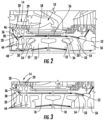
Figure 2 is a partial cross-sectional side detail view of a portion of the turbine engine with the cooling system with an inlet section downstream of the inlet taken at detail line 2-2 inFigure 1 . -
Figure 3 is a partial cross-sectional side detail view of a portion of the turbine engine with the cooling system with an inlet section downstream of the inlet taken at detail line 2-2 inFigure 1 . -
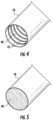
Figure 4 is a partial perspective view of a mid-frame cooling channel with ribs on the inner surface. -
Figure 5 is a partial perspective view of a mid-frame cooling channel with a roughened inner surface. -
Figure 6 is a screenshot of output from prediction software of the material temperature within a turbine engine at steady state operating conditions without the cooling system, showing the large temperature gradient within the mid-frame torque discs and high temperatures in the mid-frame torque discs. -
Figure 7 is a screenshot of output from a software prediction of the material temperature within a turbine engine at steady state operating conditions with the cooling system, showing very little temperature gradient within the mid-frame torque discs and even, cool temperatures in the mid-frame torque discs. - As shown in
Figures 1-7 , acooling system 10 configured to cool aspects of theturbine engine 12 between acompressor 14 and aturbine assembly 16 is disclosed. Thecooling system 10 includes one or moremid-frame cooling channels 18 extending from aninlet 20 through one or moremid-frame torque discs 22 positioned downstream of thecompressor 14 and upstream of theturbine assembly 16. Theinlet 20 may be positioned to receive compressor bleed air. Themid-frame cooling channel 18 is positioned in a radially outer portion of themid-frame torque disc 22 to provide cooling to outer aspects of themid-frame torque disc 22 such that conventional, low cost materials may be used to form themid-frame torque disc 22 rather than high cost materials with capacity to withstand higher temperatures. The cooling fluid routed through themid-frame cooling channel 18 in themid-frame torque disc 22 may be exhausted into acooling system 10 for thedownstream turbine assembly 16. - The
cooling system 10 for aturbine engine 12 includes acompressor 14, as shown inFigure 1 , formed form a plurality ofstages 26 positioned within acompressor chamber 28. Each of the plurality ofstages 26 includes a set of radially extendingcompressor blades 29. Thestages 26 may have any appropriate configuration. - The
cooling system 10, as shown inFigures 2 and 3 , includes one or moremid-frame cooling channels 18 extending from aninlet 20 through one or moremid-frame torque discs 22 positioned downstream of thecompressor 14 and upstream of aturbine assembly 16. Themid-frame cooling channel 18 may have any appropriate configuration. In at least one embodiment, themid-frame cooling channel 18 may be formed from a cylindrical tube. The cylindrical tube may be formed from a drilled hole in themid-frame torque disc 22. In at least one embodiment, thecooling system 10 may include a plurality ofmid-frame cooling channels 18 through one or moremid-frame torque discs 22. Thecooling system 10 may include any appropriate combination of count and size ofmid-frame cooling channels 18 to provide necessary cooling to themid-frame torque discs 22 while satisfying rotor integrity. In at least one embodiment, thecooling system 10 may include twentymid-frame cooling channels 18. In another embodiment, thecooling system 10 may include fiftymid-frame cooling channels 18. In yet another embodiment, thecooling system 10 may include seventy onemid-frame cooling channels 18. Thecooling system 10 may includecooling channels 18 numbering between twenty and one hundred. In at least one embodiment, the adjacent axiallymid-frame extending channels 18 may be positioned an equal distance in a radially outward direction from alongitudinal axis 48 of theturbine engine 12. Alternatively, two or more of the axiallymid-frame extending channels 18 may be positioned at different distances extending radially outward from thelongitudinal axis 48 of theturbine engine 12. One or more, or all, of the adjacent axiallymid-frame extending channels 18 may be positioned equidistant from each other. In other embodiments, one or more, or all, of the adjacent axiallymid-frame extending channels 18 may be positioned at alternating distances, random distances, or different distances from each other. One or more of themid-frame cooling channels 18 may have modifiedinner surfaces 40 to enhance heat transfer, as shown inFigures 4 and 5 . In particular,internal surfaces 40 of themid-frame cooling channels 18 may include heat transfer enhancement features, such as, but not limited to,ribs 42, as shown inFigure 4 , forming a ribbed surface and a highly roughened surface, as shown inFigure 5 . - The
mid-frame cooling channel 18 is positioned in an outer portion of themid-frame torque disc 22. In particular, themid-frame cooling channel 18 extends axially through themid-frame torque disc 22 within a radially outwardmost 50 percent of themid-frame torque disc 22. In another embodiment, themid-frame cooling channel 18 may extend axially through themid-frame torque disc 22 within a radially outwardmost 25 percent of themid-frame torque disc 22. Themid-frame torque disc 22 is formed from a torque disc rim 30 positioned radially outward of atorque disc hub 32. The outer andinner disc bodies torque disc web 34 having an axially extending width that is less than a width of each of thetorque disc rim 30 and thetorque disc hub 32. Themid-frame cooling channel 18 is positioned in thetorque disc rim 30. The torque disc rim 30 may form an outer 25 percent of a radially extending length of themid-frame torque disc 22. - In at least one embodiment, the
cooling system 10 may include one or more cooling fluidsupply bleed circuits 38. The cooling fluidsupply bleed circuit 38 may supply cooling fluid to thecooling system 10. In other embodiments, thecooling system 10 may receive cooling fluid as bleed air directly from thecompressor chamber 28 of thecompressor 14. The cooling fluidsupply bleed circuit 38 may include ableed inlet 36 that may place the cooling fluidsupply bleed circuit 38 in fluid communication with thecompressor chamber 28 for receiving fluid from thecompressor chamber 28. In at least one embodiment, theinlet 20 of themid-frame cooling channel 18 may be in fluid communication with the cooling fluidsupply bleed circuit 38. In other embodiments, theinlet 20 of themid-frame cooling channel 18 may be in fluid communication with thecompressor chamber 28 of thecompressor 14 to receive compressor bleed fluid, such as, but not limited to, air. Themid-frame cooling channel 18 may extend from theinlet 20 into one ormore compressor discs 44 positioned upstream of themid-frame torque disc 22. Thecooling system 10 may also include aninlet section 46 in communication with theinlet 20 and immediately downstream from theinlet 20. Theinlet section 46 may be non-parallel and non-orthogonal to alongitudinal axis 48 of theturbine engine 12. Theinlet section 46 may be misaligned against the rotating direction of thecompressor blades 29 to create de-swirling action for minimum pressure drop. - As shown in
Figures 2 and 3 , one or more of themid-frame cooling channels 18 may include anoutlet 52 in theturbine assembly 16. Themid-frame cooling channel 18 may extend from themid-frame torque disc 22 into one ormore turbine discs 50 positioned downstream of themid-frame torque disc 22. Theoutlet 52 in theturbine assembly 16 may be configured to exhaust cooling fluid into aturbine disc 50 of turbine stage two to supply aturbine assembly 16 with cooling fluid. One or more of themid-frame cooling channels 18 also include anoutlet section 54 in communication with theoutlet 52 of thecooling system 10. Theoutlet section 54 is positioned immediately upstream from theoutlet 52. - The
outlet section 54 is non-parallel and non-orthogonal to alongitudinal axis 48 of theturbine engine 12. Theoutlet section 54 is positioned against the rotating direction to create de-swirling action for minimum pressure drop. - The
cooling system 10 may include athermal barrier coating 56 on a radiallyouter surface 58 of themid-frame torque disc 22. Thethermal barrier coating 56 on a radiallyouter surface 58 of themid-frame torque disc 22 may be aligned radially outward from themid-frame cooling channel 18. Thethermal barrier coating 56 may be any appropriate thermal barrier coating already conceived or yet to be conceived. Thethermal barrier coating 56 may be positioned in critical regions of theouter surface 58 of themid-frame torque disc 22 exposed to hot air or windage heat pickup for further temperature reduction of themid-frame torque discs 22. - During use, compressed air is bleed off of the
compressor 14 via one ormore inlets 20 in fluid communication with thecompressor chamber 28. Theinlet 20 may be in fluid communication with thecompressor chamber 28 via direct coupled to thecompressor chamber 28 or indirectly, such as in communication with thecompressor chamber 28 via the cooling fluidsupply bleed circuit 38. The cooling fluid, which may be, but is not limited to being, air, may enter theinlet 20 and immediately flow into theinlet section 46 which is misaligned against the rotating direction of thecompressor blades 29 to create de-swirling action for minimum pressure drop. The cooling fluid then flows downstream through themid-frame cooling channels 18, thereby cooling the hotter outer portions of the one or moremid-frame torque discs 22. The cooling fluid increases in temperature flowing through the hotter outer portions of the one or moremid-frame torque discs 22. The cooling fluid may be exhausted from themid-frame cooling channels 18 via theoutlet section 54 and theoutlet 52. The cooling fluid may be exhausted into one ormore turbine discs 50 positioned downstream of themid-frame torque disc 22. The exhausted cooling fluid may be used to cool aspects of the components of theturbine assembly 16. The cooling experienced via thecooling system 10 within themid-frame torque discs 22 is shown inFigure 7 in contrast to the large temperature gradient within the mid-frame torque discs and high temperatures in themid-frame torque discs 22 shown inFigure 6 . - The foregoing is provided for purposes of illustrating, explaining, and describing embodiments of this invention. Modifications and adaptations to these embodiments will be apparent to those skilled in the art and may be made without departing from the scope of the invention, as defined in the appended claims.
Claims (12)
- A cooling system (10) for a turbine engine (12), comprising:a compressor (14) formed from a plurality of stages (26) positioned within a compressor chamber (28), each of the plurality of stages (26) includes a set of radially extending compressor blades (29); andat least one mid-frame cooling channel (18) extending from an inlet (20) through at least one mid-frame torque disc (22) positioned downstream of the compressor (14) and upstream of a turbine assembly (16),wherein the at least one mid-frame torque disc (22) is formed from a torque disc rim (30) positioned radially outward of a torque disc hub (32),wherein the torque disc rim (30) and the torque disc hub (32) are separated by a torque disc web (34) having an axially extending width that is less than both the torque disc rim (30) and the torque disc hub (32),wherein the at least one mid-frame cooling channel (18) is positioned in the torque disc rim (30), andwherein the at least one mid-frame cooling channel (18) extends axially through the at least one mid-frame torque disc (22) within a radially outwardmost 50 percent of the at least one mid-frame torque disc (22),further comprising an outlet section (54) in communication with an outlet (52) of the cooling system (10), wherein the outlet section (54) is positioned immediately upstream from the outlet (52), wherein the outlet section (54) is non-parallel and non-orthogonal to a longitudinal axis (48) of the turbine engine (12) and positioned against a rotating direction of the turbine engine to create deswirling action for minimum pressure drop.
- The cooling system (10) of claim 1, further characterized in that it further comprises at least one cooling fluid supply bleed circuit (38) with a bleed inlet (36) placing the at least one bleed circuit (38) in fluid communication with the compressor chamber (28) for receiving fluid from the compressor chamber (28) and wherein the inlet (20) of the at least one mid-frame cooling channel (18) is in fluid communication with the at least one cooling fluid supply bleed circuit (38).
- The cooling system (10) of claim 1, characterized in that the at least one mid-frame cooling channel (18) extends from the inlet (20) into at least one compressor disc (44) positioned upstream of the at least one mid-frame torque disc (22).
- The cooling system (10) of claim 1, further characterized in that it furher comprises an inlet section (46) in communication with the inlet (20) and immediately downstream from the inlet (20), wherein the inlet section (46) is non-parallel and non-orthogonal to a longitudinal axis of the turbine engine (12).
- The cooling system (10) of claim 1, characterized in that the at least one mid-frame cooling channel (18) extends axially through the at least one mid-frame torque disc (22) within a radially outwardmost 25 percent of the at least one mid-frame torque disc (22).
- The cooling system (10) of claim 1, characterized in that the at least one mid-frame cooling channel (18) comprises a plurality of axially extending mid-frame channels (18) extending axially through the at least one mid-frame torque disc (22).
- The cooling system (10) of claim 6, characterized in that adjacent axially mid-frame extending channels (18) are positioned equidistant from each other and wherein adjacent axially mid-frame extending channels (18) are positioned an equal distance in a radially outward direction from a longitudinal axis (48) of the turbine engine (12).
- The cooling system (10) of claim 1, characterized in that the at least one mid-frame cooling channel (18) extends from the at least one mid-frame torque disc (22) into at least one turbine disc (50) positioned downstream of the at least one mid-frame torque disc (22), wherein the at least one mid-frame cooling channel (18) includes at least one outlet (52) in the turbine assembly (16) and wherein the at least one mid-frame cooling channel (18) is formed from a cylindrical tube.
- The cooling system (10) of claim 1, further characterized in that it further comprises at least one internal rib (42) extending from an internal surface (40) of the at least one mid-frame cooling channel (18).
- The cooling system (10) of claim 1, further characterized in that it further comprises a roughened surface forming an internal surface (40) of the at least one mid-frame cooling channel (18).
- The cooling system (10) of claim 1, further characterized in that it further comprises a thermal barrier coating (56) on a radially outer surface (58) of the at least one mid-frame torque disc (22) and aligned radially outward from the at least one mid-frame cooling channel (18).
- A turbine engine (12) comprising:
a cooling system (10) according to any one of claims 1 to 11.
Applications Claiming Priority (1)
| Application Number | Priority Date | Filing Date | Title |
|---|---|---|---|
| PCT/US2016/020186 WO2017151110A1 (en) | 2016-03-01 | 2016-03-01 | Compressor bleed cooling system for mid-frame torque discs downstream from a compressor assembly in a gas turbine engine |
Publications (2)
| Publication Number | Publication Date |
|---|---|
| EP3390780A1 EP3390780A1 (en) | 2018-10-24 |
| EP3390780B1 true EP3390780B1 (en) | 2023-05-03 |
Family
ID=55521859
Family Applications (1)
| Application Number | Title | Priority Date | Filing Date |
|---|---|---|---|
| EP16709243.6A Active EP3390780B1 (en) | 2016-03-01 | 2016-03-01 | Cooling system for mid-frame torque discs downstream from a compressor assembly in a gas turbine engine |
Country Status (6)
| Country | Link |
|---|---|
| US (1) | US10830146B2 (en) |
| EP (1) | EP3390780B1 (en) |
| JP (1) | JP6584687B2 (en) |
| KR (1) | KR102052029B1 (en) |
| CN (1) | CN108699913B (en) |
| WO (1) | WO2017151110A1 (en) |
Families Citing this family (4)
| Publication number | Priority date | Publication date | Assignee | Title |
|---|---|---|---|---|
| KR101744411B1 (en) * | 2015-10-15 | 2017-06-20 | 두산중공업 주식회사 | Cooling apparatus of the gas turbine |
| US10273812B2 (en) | 2015-12-18 | 2019-04-30 | Pratt & Whitney Canada Corp. | Turbine rotor coolant supply system |
| US11377957B2 (en) * | 2017-05-09 | 2022-07-05 | General Electric Company | Gas turbine engine with a diffuser cavity cooled compressor |
| US12203386B2 (en) * | 2022-02-18 | 2025-01-21 | Rtx Corporation | Compressor-turbine rotating assembly with integral cooling circuit(s) |
Citations (2)
| Publication number | Priority date | Publication date | Assignee | Title |
|---|---|---|---|---|
| EP3147451A1 (en) * | 2015-09-23 | 2017-03-29 | Doosan Heavy Industries & Construction Co., Ltd. | System for cooling gas turbine |
| EP3156593A1 (en) * | 2015-10-15 | 2017-04-19 | Doosan Heavy Industries & Construction Co., Ltd. | Cooling apparatus of gas turbine |
Family Cites Families (17)
| Publication number | Priority date | Publication date | Assignee | Title |
|---|---|---|---|---|
| JPH09195702A (en) | 1996-01-18 | 1997-07-29 | Hitachi Ltd | Gas turbine, gas turbine blade cooling device, and gas turbine blade cooling method |
| US5558496A (en) * | 1995-08-21 | 1996-09-24 | General Electric Company | Removing particles from gas turbine coolant |
| US5735671A (en) * | 1996-11-29 | 1998-04-07 | General Electric Company | Shielded turbine rotor |
| JP4040773B2 (en) * | 1998-12-01 | 2008-01-30 | 株式会社東芝 | Gas turbine plant |
| EP1577493A1 (en) * | 2004-03-17 | 2005-09-21 | Siemens Aktiengesellschaft | Turbomachine and rotor for a turbomachine |
| US20070201980A1 (en) * | 2005-10-11 | 2007-08-30 | Honeywell International, Inc. | Method to augment heat transfer using chamfered cylindrical depressions in cast internal cooling passages |
| US20070271930A1 (en) | 2006-05-03 | 2007-11-29 | Mitsubishi Heavy Industries, Ltd. | Gas turbine having cooling-air transfer system |
| WO2008045054A1 (en) | 2006-10-12 | 2008-04-17 | United Technologies Corporation | Modulating flow through gas turbine engine cooling system |
| DE102007023380A1 (en) * | 2007-05-18 | 2008-11-20 | Mtu Aero Engines Gmbh | gas turbine |
| EP2255072B1 (en) * | 2008-03-28 | 2015-05-06 | Alstom Technology Ltd | Guide vane for a gas turbine and gas turbine comprising such a guide vane |
| US8677763B2 (en) * | 2009-03-10 | 2014-03-25 | General Electric Company | Method and apparatus for gas turbine engine temperature management |
| DE102010035393B4 (en) * | 2010-08-25 | 2014-09-04 | Siemens Aktiengesellschaft | Turbine and method for operating a turbine for a CAES system |
| US9562475B2 (en) * | 2012-12-19 | 2017-02-07 | Siemens Aktiengesellschaft | Vane carrier temperature control system in a gas turbine engine |
| US9951621B2 (en) * | 2013-06-05 | 2018-04-24 | Siemens Aktiengesellschaft | Rotor disc with fluid removal channels to enhance life of spindle bolt |
| US9574498B2 (en) * | 2013-09-25 | 2017-02-21 | General Electric Company | Internally cooled transition duct aft frame with serpentine cooling passage and conduit |
| US9518478B2 (en) * | 2013-10-28 | 2016-12-13 | General Electric Company | Microchannel exhaust for cooling and/or purging gas turbine segment gaps |
| KR101788413B1 (en) * | 2015-12-01 | 2017-10-19 | 두산중공업 주식회사 | Disk assembly and a turbine using the same |
-
2016
- 2016-03-01 EP EP16709243.6A patent/EP3390780B1/en active Active
- 2016-03-01 KR KR1020187027251A patent/KR102052029B1/en active Active
- 2016-03-01 US US16/070,070 patent/US10830146B2/en active Active
- 2016-03-01 JP JP2018545926A patent/JP6584687B2/en active Active
- 2016-03-01 CN CN201680082695.XA patent/CN108699913B/en active Active
- 2016-03-01 WO PCT/US2016/020186 patent/WO2017151110A1/en not_active Ceased
Patent Citations (2)
| Publication number | Priority date | Publication date | Assignee | Title |
|---|---|---|---|---|
| EP3147451A1 (en) * | 2015-09-23 | 2017-03-29 | Doosan Heavy Industries & Construction Co., Ltd. | System for cooling gas turbine |
| EP3156593A1 (en) * | 2015-10-15 | 2017-04-19 | Doosan Heavy Industries & Construction Co., Ltd. | Cooling apparatus of gas turbine |
Also Published As
| Publication number | Publication date |
|---|---|
| WO2017151110A1 (en) | 2017-09-08 |
| JP6584687B2 (en) | 2019-10-02 |
| EP3390780A1 (en) | 2018-10-24 |
| US10830146B2 (en) | 2020-11-10 |
| CN108699913B (en) | 2020-05-05 |
| US20190010871A1 (en) | 2019-01-10 |
| KR102052029B1 (en) | 2019-12-04 |
| KR20180112050A (en) | 2018-10-11 |
| CN108699913A (en) | 2018-10-23 |
| JP2019511665A (en) | 2019-04-25 |
Similar Documents
| Publication | Publication Date | Title |
|---|---|---|
| EP2834498B1 (en) | Cooling system for a turbine vane | |
| US20100239432A1 (en) | Turbine Vane for a Gas Turbine Engine Having Serpentine Cooling Channels Within the Inner Endwall | |
| CN106907182B (en) | Turbine airfoil with trailing edge cooling circuit | |
| CN106907183B (en) | Turbine airfoil with trailing edge cooling circuit | |
| US7600966B2 (en) | Turbine airfoil with improved cooling | |
| EP3203024B1 (en) | Rotor blade and corresponding gas turbine | |
| US10830146B2 (en) | Compressor bleed cooling system for mid-frame torque discs downstream from a compressor assembly in a gas turbine engine | |
| US9528380B2 (en) | Turbine bucket and method for cooling a turbine bucket of a gas turbine engine | |
| EP3081754B1 (en) | Turbine airfoil | |
| US9500093B2 (en) | Internally cooled airfoil | |
| EP2867479B1 (en) | Component for a gas turbine engine and corresponding gas turbine engine | |
| EP3152402A1 (en) | Turbine airfoil cooling system with platform cooling channels | |
| US10138735B2 (en) | Turbine airfoil internal core profile | |
| US20130236329A1 (en) | Rotor blade with one or more side wall cooling circuits | |
| CA3029022A1 (en) | Combustor assemblies for use in turbine engines and methods of assembling same | |
| EP3159497B1 (en) | System and method for wheel space temperature management | |
| US20170211394A1 (en) | Gas turbine blade with pedestal array |
Legal Events
| Date | Code | Title | Description |
|---|---|---|---|
| STAA | Information on the status of an ep patent application or granted ep patent |
Free format text: STATUS: THE INTERNATIONAL PUBLICATION HAS BEEN MADE |
|
| PUAI | Public reference made under article 153(3) epc to a published international application that has entered the european phase |
Free format text: ORIGINAL CODE: 0009012 |
|
| STAA | Information on the status of an ep patent application or granted ep patent |
Free format text: STATUS: REQUEST FOR EXAMINATION WAS MADE |
|
| 17P | Request for examination filed |
Effective date: 20180717 |
|
| AK | Designated contracting states |
Kind code of ref document: A1 Designated state(s): AL AT BE BG CH CY CZ DE DK EE ES FI FR GB GR HR HU IE IS IT LI LT LU LV MC MK MT NL NO PL PT RO RS SE SI SK SM TR |
|
| AX | Request for extension of the european patent |
Extension state: BA ME |
|
| STAA | Information on the status of an ep patent application or granted ep patent |
Free format text: STATUS: EXAMINATION IS IN PROGRESS |
|
| 17Q | First examination report despatched |
Effective date: 20190507 |
|
| DAV | Request for validation of the european patent (deleted) | ||
| DAX | Request for extension of the european patent (deleted) | ||
| RAP1 | Party data changed (applicant data changed or rights of an application transferred) |
Owner name: SIEMENS ENERGY GLOBAL GMBH & CO. KG |
|
| GRAP | Despatch of communication of intention to grant a patent |
Free format text: ORIGINAL CODE: EPIDOSNIGR1 |
|
| STAA | Information on the status of an ep patent application or granted ep patent |
Free format text: STATUS: GRANT OF PATENT IS INTENDED |
|
| INTG | Intention to grant announced |
Effective date: 20221220 |
|
| GRAS | Grant fee paid |
Free format text: ORIGINAL CODE: EPIDOSNIGR3 |
|
| GRAA | (expected) grant |
Free format text: ORIGINAL CODE: 0009210 |
|
| STAA | Information on the status of an ep patent application or granted ep patent |
Free format text: STATUS: THE PATENT HAS BEEN GRANTED |
|
| AK | Designated contracting states |
Kind code of ref document: B1 Designated state(s): AL AT BE BG CH CY CZ DE DK EE ES FI FR GB GR HR HU IE IS IT LI LT LU LV MC MK MT NL NO PL PT RO RS SE SI SK SM TR |
|
| REG | Reference to a national code |
Ref country code: GB Ref legal event code: FG4D |
|
| REG | Reference to a national code |
Ref country code: DE Ref legal event code: R096 Ref document number: 602016079159 Country of ref document: DE |
|
| REG | Reference to a national code |
Ref country code: AT Ref legal event code: REF Ref document number: 1564745 Country of ref document: AT Kind code of ref document: T Effective date: 20230515 Ref country code: CH Ref legal event code: EP |
|
| REG | Reference to a national code |
Ref country code: IE Ref legal event code: FG4D |
|
| REG | Reference to a national code |
Ref country code: LT Ref legal event code: MG9D |
|
| REG | Reference to a national code |
Ref country code: NL Ref legal event code: MP Effective date: 20230503 |
|
| REG | Reference to a national code |
Ref country code: AT Ref legal event code: MK05 Ref document number: 1564745 Country of ref document: AT Kind code of ref document: T Effective date: 20230503 |
|
| PG25 | Lapsed in a contracting state [announced via postgrant information from national office to epo] |
Ref country code: SE Free format text: LAPSE BECAUSE OF FAILURE TO SUBMIT A TRANSLATION OF THE DESCRIPTION OR TO PAY THE FEE WITHIN THE PRESCRIBED TIME-LIMIT Effective date: 20230503 Ref country code: PT Free format text: LAPSE BECAUSE OF FAILURE TO SUBMIT A TRANSLATION OF THE DESCRIPTION OR TO PAY THE FEE WITHIN THE PRESCRIBED TIME-LIMIT Effective date: 20230904 Ref country code: NO Free format text: LAPSE BECAUSE OF FAILURE TO SUBMIT A TRANSLATION OF THE DESCRIPTION OR TO PAY THE FEE WITHIN THE PRESCRIBED TIME-LIMIT Effective date: 20230803 Ref country code: NL Free format text: LAPSE BECAUSE OF FAILURE TO SUBMIT A TRANSLATION OF THE DESCRIPTION OR TO PAY THE FEE WITHIN THE PRESCRIBED TIME-LIMIT Effective date: 20230503 Ref country code: ES Free format text: LAPSE BECAUSE OF FAILURE TO SUBMIT A TRANSLATION OF THE DESCRIPTION OR TO PAY THE FEE WITHIN THE PRESCRIBED TIME-LIMIT Effective date: 20230503 Ref country code: AT Free format text: LAPSE BECAUSE OF FAILURE TO SUBMIT A TRANSLATION OF THE DESCRIPTION OR TO PAY THE FEE WITHIN THE PRESCRIBED TIME-LIMIT Effective date: 20230503 |
|
| PG25 | Lapsed in a contracting state [announced via postgrant information from national office to epo] |
Ref country code: RS Free format text: LAPSE BECAUSE OF FAILURE TO SUBMIT A TRANSLATION OF THE DESCRIPTION OR TO PAY THE FEE WITHIN THE PRESCRIBED TIME-LIMIT Effective date: 20230503 Ref country code: PL Free format text: LAPSE BECAUSE OF FAILURE TO SUBMIT A TRANSLATION OF THE DESCRIPTION OR TO PAY THE FEE WITHIN THE PRESCRIBED TIME-LIMIT Effective date: 20230503 Ref country code: LV Free format text: LAPSE BECAUSE OF FAILURE TO SUBMIT A TRANSLATION OF THE DESCRIPTION OR TO PAY THE FEE WITHIN THE PRESCRIBED TIME-LIMIT Effective date: 20230503 Ref country code: LT Free format text: LAPSE BECAUSE OF FAILURE TO SUBMIT A TRANSLATION OF THE DESCRIPTION OR TO PAY THE FEE WITHIN THE PRESCRIBED TIME-LIMIT Effective date: 20230503 Ref country code: IS Free format text: LAPSE BECAUSE OF FAILURE TO SUBMIT A TRANSLATION OF THE DESCRIPTION OR TO PAY THE FEE WITHIN THE PRESCRIBED TIME-LIMIT Effective date: 20230903 Ref country code: HR Free format text: LAPSE BECAUSE OF FAILURE TO SUBMIT A TRANSLATION OF THE DESCRIPTION OR TO PAY THE FEE WITHIN THE PRESCRIBED TIME-LIMIT Effective date: 20230503 Ref country code: GR Free format text: LAPSE BECAUSE OF FAILURE TO SUBMIT A TRANSLATION OF THE DESCRIPTION OR TO PAY THE FEE WITHIN THE PRESCRIBED TIME-LIMIT Effective date: 20230804 |
|
| PG25 | Lapsed in a contracting state [announced via postgrant information from national office to epo] |
Ref country code: FI Free format text: LAPSE BECAUSE OF FAILURE TO SUBMIT A TRANSLATION OF THE DESCRIPTION OR TO PAY THE FEE WITHIN THE PRESCRIBED TIME-LIMIT Effective date: 20230503 |
|
| PG25 | Lapsed in a contracting state [announced via postgrant information from national office to epo] |
Ref country code: SK Free format text: LAPSE BECAUSE OF FAILURE TO SUBMIT A TRANSLATION OF THE DESCRIPTION OR TO PAY THE FEE WITHIN THE PRESCRIBED TIME-LIMIT Effective date: 20230503 |
|
| PG25 | Lapsed in a contracting state [announced via postgrant information from national office to epo] |
Ref country code: SM Free format text: LAPSE BECAUSE OF FAILURE TO SUBMIT A TRANSLATION OF THE DESCRIPTION OR TO PAY THE FEE WITHIN THE PRESCRIBED TIME-LIMIT Effective date: 20230503 Ref country code: SK Free format text: LAPSE BECAUSE OF FAILURE TO SUBMIT A TRANSLATION OF THE DESCRIPTION OR TO PAY THE FEE WITHIN THE PRESCRIBED TIME-LIMIT Effective date: 20230503 Ref country code: RO Free format text: LAPSE BECAUSE OF FAILURE TO SUBMIT A TRANSLATION OF THE DESCRIPTION OR TO PAY THE FEE WITHIN THE PRESCRIBED TIME-LIMIT Effective date: 20230503 Ref country code: EE Free format text: LAPSE BECAUSE OF FAILURE TO SUBMIT A TRANSLATION OF THE DESCRIPTION OR TO PAY THE FEE WITHIN THE PRESCRIBED TIME-LIMIT Effective date: 20230503 Ref country code: DK Free format text: LAPSE BECAUSE OF FAILURE TO SUBMIT A TRANSLATION OF THE DESCRIPTION OR TO PAY THE FEE WITHIN THE PRESCRIBED TIME-LIMIT Effective date: 20230503 Ref country code: CZ Free format text: LAPSE BECAUSE OF FAILURE TO SUBMIT A TRANSLATION OF THE DESCRIPTION OR TO PAY THE FEE WITHIN THE PRESCRIBED TIME-LIMIT Effective date: 20230503 |
|
| REG | Reference to a national code |
Ref country code: DE Ref legal event code: R097 Ref document number: 602016079159 Country of ref document: DE |
|
| PLBE | No opposition filed within time limit |
Free format text: ORIGINAL CODE: 0009261 |
|
| STAA | Information on the status of an ep patent application or granted ep patent |
Free format text: STATUS: NO OPPOSITION FILED WITHIN TIME LIMIT |
|
| 26N | No opposition filed |
Effective date: 20240206 |
|
| PG25 | Lapsed in a contracting state [announced via postgrant information from national office to epo] |
Ref country code: SI Free format text: LAPSE BECAUSE OF FAILURE TO SUBMIT A TRANSLATION OF THE DESCRIPTION OR TO PAY THE FEE WITHIN THE PRESCRIBED TIME-LIMIT Effective date: 20230503 |
|
| PG25 | Lapsed in a contracting state [announced via postgrant information from national office to epo] |
Ref country code: SI Free format text: LAPSE BECAUSE OF FAILURE TO SUBMIT A TRANSLATION OF THE DESCRIPTION OR TO PAY THE FEE WITHIN THE PRESCRIBED TIME-LIMIT Effective date: 20230503 |
|
| PG25 | Lapsed in a contracting state [announced via postgrant information from national office to epo] |
Ref country code: BG Free format text: LAPSE BECAUSE OF FAILURE TO SUBMIT A TRANSLATION OF THE DESCRIPTION OR TO PAY THE FEE WITHIN THE PRESCRIBED TIME-LIMIT Effective date: 20230503 |
|
| PG25 | Lapsed in a contracting state [announced via postgrant information from national office to epo] |
Ref country code: LU Free format text: LAPSE BECAUSE OF NON-PAYMENT OF DUE FEES Effective date: 20240301 |
|
| PG25 | Lapsed in a contracting state [announced via postgrant information from national office to epo] |
Ref country code: MC Free format text: LAPSE BECAUSE OF FAILURE TO SUBMIT A TRANSLATION OF THE DESCRIPTION OR TO PAY THE FEE WITHIN THE PRESCRIBED TIME-LIMIT Effective date: 20230503 |
|
| GBPC | Gb: european patent ceased through non-payment of renewal fee |
Effective date: 20240301 |
|
| PG25 | Lapsed in a contracting state [announced via postgrant information from national office to epo] |
Ref country code: MC Free format text: LAPSE BECAUSE OF FAILURE TO SUBMIT A TRANSLATION OF THE DESCRIPTION OR TO PAY THE FEE WITHIN THE PRESCRIBED TIME-LIMIT Effective date: 20230503 Ref country code: LU Free format text: LAPSE BECAUSE OF NON-PAYMENT OF DUE FEES Effective date: 20240301 Ref country code: BG Free format text: LAPSE BECAUSE OF FAILURE TO SUBMIT A TRANSLATION OF THE DESCRIPTION OR TO PAY THE FEE WITHIN THE PRESCRIBED TIME-LIMIT Effective date: 20230503 |
|
| REG | Reference to a national code |
Ref country code: BE Ref legal event code: MM Effective date: 20240331 |
|
| PG25 | Lapsed in a contracting state [announced via postgrant information from national office to epo] |
Ref country code: BE Free format text: LAPSE BECAUSE OF NON-PAYMENT OF DUE FEES Effective date: 20240331 |
|
| PG25 | Lapsed in a contracting state [announced via postgrant information from national office to epo] |
Ref country code: GB Free format text: LAPSE BECAUSE OF NON-PAYMENT OF DUE FEES Effective date: 20240301 |
|
| PG25 | Lapsed in a contracting state [announced via postgrant information from national office to epo] |
Ref country code: FR Free format text: LAPSE BECAUSE OF NON-PAYMENT OF DUE FEES Effective date: 20240331 |
|
| PG25 | Lapsed in a contracting state [announced via postgrant information from national office to epo] |
Ref country code: IE Free format text: LAPSE BECAUSE OF NON-PAYMENT OF DUE FEES Effective date: 20240301 |
|
| PG25 | Lapsed in a contracting state [announced via postgrant information from national office to epo] |
Ref country code: IE Free format text: LAPSE BECAUSE OF NON-PAYMENT OF DUE FEES Effective date: 20240301 Ref country code: GB Free format text: LAPSE BECAUSE OF NON-PAYMENT OF DUE FEES Effective date: 20240301 Ref country code: FR Free format text: LAPSE BECAUSE OF NON-PAYMENT OF DUE FEES Effective date: 20240331 Ref country code: BE Free format text: LAPSE BECAUSE OF NON-PAYMENT OF DUE FEES Effective date: 20240331 |
|
| PG25 | Lapsed in a contracting state [announced via postgrant information from national office to epo] |
Ref country code: CY Free format text: LAPSE BECAUSE OF FAILURE TO SUBMIT A TRANSLATION OF THE DESCRIPTION OR TO PAY THE FEE WITHIN THE PRESCRIBED TIME-LIMIT; INVALID AB INITIO Effective date: 20160301 |
|
| PG25 | Lapsed in a contracting state [announced via postgrant information from national office to epo] |
Ref country code: HU Free format text: LAPSE BECAUSE OF FAILURE TO SUBMIT A TRANSLATION OF THE DESCRIPTION OR TO PAY THE FEE WITHIN THE PRESCRIBED TIME-LIMIT; INVALID AB INITIO Effective date: 20160301 |
|
| PG25 | Lapsed in a contracting state [announced via postgrant information from national office to epo] |
Ref country code: TR Free format text: LAPSE BECAUSE OF FAILURE TO SUBMIT A TRANSLATION OF THE DESCRIPTION OR TO PAY THE FEE WITHIN THE PRESCRIBED TIME-LIMIT Effective date: 20230503 |
|
| REG | Reference to a national code |
Ref country code: CH Ref legal event code: U11 Free format text: ST27 STATUS EVENT CODE: U-0-0-U10-U11 (AS PROVIDED BY THE NATIONAL OFFICE) Effective date: 20260401 |
|
| PGFP | Annual fee paid to national office [announced via postgrant information from national office to epo] |
Ref country code: DE Payment date: 20260320 Year of fee payment: 11 |
|
| PGFP | Annual fee paid to national office [announced via postgrant information from national office to epo] |
Ref country code: IT Payment date: 20260320 Year of fee payment: 11 |
|
| PGFP | Annual fee paid to national office [announced via postgrant information from national office to epo] |
Ref country code: CH Payment date: 20260401 Year of fee payment: 11 |