EP3390733B1 - Plumbing fixtures - Google Patents
Plumbing fixtures Download PDFInfo
- Publication number
- EP3390733B1 EP3390733B1 EP16808781.5A EP16808781A EP3390733B1 EP 3390733 B1 EP3390733 B1 EP 3390733B1 EP 16808781 A EP16808781 A EP 16808781A EP 3390733 B1 EP3390733 B1 EP 3390733B1
- Authority
- EP
- European Patent Office
- Prior art keywords
- inlet
- valve
- hot
- cold
- faucet
- Prior art date
- Legal status (The legal status is an assumption and is not a legal conclusion. Google has not performed a legal analysis and makes no representation as to the accuracy of the status listed.)
- Active
Links
- 238000009428 plumbing Methods 0.000 title 1
- XLYOFNOQVPJJNP-UHFFFAOYSA-N water Substances O XLYOFNOQVPJJNP-UHFFFAOYSA-N 0.000 claims description 99
- 239000012530 fluid Substances 0.000 claims description 30
- 239000007787 solid Substances 0.000 claims description 9
- 238000000034 method Methods 0.000 claims description 5
- 230000000007 visual effect Effects 0.000 claims description 3
- 230000000903 blocking effect Effects 0.000 claims description 2
- 239000003550 marker Substances 0.000 claims description 2
- 238000007789 sealing Methods 0.000 description 23
- 238000012986 modification Methods 0.000 description 7
- 230000004048 modification Effects 0.000 description 7
- 239000007921 spray Substances 0.000 description 5
- 230000015572 biosynthetic process Effects 0.000 description 4
- 238000005755 formation reaction Methods 0.000 description 4
- 230000000712 assembly Effects 0.000 description 2
- 238000000429 assembly Methods 0.000 description 2
- 238000003780 insertion Methods 0.000 description 2
- 230000037431 insertion Effects 0.000 description 2
- 238000009434 installation Methods 0.000 description 2
- 239000002775 capsule Substances 0.000 description 1
- 238000004891 communication Methods 0.000 description 1
- 230000000295 complement effect Effects 0.000 description 1
- 230000006835 compression Effects 0.000 description 1
- 238000007906 compression Methods 0.000 description 1
- 230000008878 coupling Effects 0.000 description 1
- 238000010168 coupling process Methods 0.000 description 1
- 238000005859 coupling reaction Methods 0.000 description 1
- 239000013536 elastomeric material Substances 0.000 description 1
- 230000001747 exhibiting effect Effects 0.000 description 1
- 230000001771 impaired effect Effects 0.000 description 1
- 239000000463 material Substances 0.000 description 1
- 238000012544 monitoring process Methods 0.000 description 1
- 230000000750 progressive effect Effects 0.000 description 1
Images




Classifications
-
- E—FIXED CONSTRUCTIONS
- E03—WATER SUPPLY; SEWERAGE
- E03C—DOMESTIC PLUMBING INSTALLATIONS FOR FRESH WATER OR WASTE WATER; SINKS
- E03C1/00—Domestic plumbing installations for fresh water or waste water; Sinks
- E03C1/02—Plumbing installations for fresh water
- E03C1/04—Water-basin installations specially adapted to wash-basins or baths
- E03C1/0403—Connecting the supply lines to the tap body
-
- E—FIXED CONSTRUCTIONS
- E03—WATER SUPPLY; SEWERAGE
- E03C—DOMESTIC PLUMBING INSTALLATIONS FOR FRESH WATER OR WASTE WATER; SINKS
- E03C1/00—Domestic plumbing installations for fresh water or waste water; Sinks
- E03C1/02—Plumbing installations for fresh water
- E03C1/04—Water-basin installations specially adapted to wash-basins or baths
- E03C1/0408—Water installations especially for showers
-
- G—PHYSICS
- G05—CONTROLLING; REGULATING
- G05D—SYSTEMS FOR CONTROLLING OR REGULATING NON-ELECTRIC VARIABLES
- G05D23/00—Control of temperature
- G05D23/01—Control of temperature without auxiliary power
- G05D23/13—Control of temperature without auxiliary power by varying the mixing ratio of two fluids having different temperatures
- G05D23/1306—Control of temperature without auxiliary power by varying the mixing ratio of two fluids having different temperatures for liquids
- G05D23/132—Control of temperature without auxiliary power by varying the mixing ratio of two fluids having different temperatures for liquids with temperature sensing element
- G05D23/134—Control of temperature without auxiliary power by varying the mixing ratio of two fluids having different temperatures for liquids with temperature sensing element measuring the temperature of mixed fluid
- G05D23/1346—Control of temperature without auxiliary power by varying the mixing ratio of two fluids having different temperatures for liquids with temperature sensing element measuring the temperature of mixed fluid with manual temperature setting means
Definitions
- This invention relates to a faucet according to the preamble of claim 1, and to a method of installing a faucet according to the preamble of claim 15.
- the invention has particular, but not exclusive, application to mixer valves for shower systems.
- a shower mixer valve has separate inlets for connection to supplies of hot and cold water and an outlet for connection to a shower head such as a handset or a spray head.
- a shower head such as a handset or a spray head.
- the pipework for the hot and cold supplies must be plumbed into position for connection to the inlets. It is an industry standard in the UK that the hot supply is on the left hand side and the cold supply is on the right hand side and shower mixer valves are configured with the inlets arranged accordingly for connection to the hot and cold supplies.
- a typical shower mixer valve comprises a valve body housing a cartridge designed to mix hot and cold water to provide outlet water having a desired temperature.
- the cartridge has hot and cold sides separated from one another for receiving hot and cold water from the inlets and this arrangement requires the inlets to be connected to the correct supplies. However, sometimes by mistake or other reason the arrangement of the pipework may be reversed so that the cold supply is on the left hand side and the hot supply is on the right hand side. If the valve is installed with the inlets connected to the wrong supplies, i.e. the cold inlet connected to the hot supply and the hot inlet connected to the cold supply, the valve may not function correctly and/or performance may be impaired.
- valve One solution to the problem of installing the valve when the arrangement of the pipework is reversed from the industry standard is to provide the valve with two outlets, one on the top and another on the bottom of the valve body. This allows the installer to rotate the whole valve through 180 degrees to connect the inlets to the correct supplies and connect one of the outlets for supplying outlet water to a spray fitting such as a handset or spray head. With this arrangement the outlet that is not used is closed with a blanking plug. This is a relatively simple solution but is not aesthetically pleasing as the blanking plug is always visible.
- DE3643528A1 describes a device for the wall connection of a mixer unit with reverse arranged hot and cold water supply lines in order to produce a standard connection gauge for sanitary mixer units.
- a first angle piece can be connected to a connection piece and can be joined to a second angle piece, exhibiting a connection opening for the mixer unit.
- GB1441243A describes a hot and cold water mixing valve in which an inlet valve member varies inversely the openings of the inlets according to the movements of a thermostat and moves relative the inlets on rotation of a rotary but axially fixed control member which is connected by a buttress thread to a sleeve that acts via a prestressed spring and an adjustment screw in a member on the end of the thermostat.
- GB2340210A describes a mixing valve for the supply of temperature controlled water to an ablutionary appliance such as a shower in which a valve member 35 is axially movable between a cold seat and a hot seat to control and regulate mixing of hot and cold water in accordance with adjustable selection of outlet water temperature.
- WO02/46853A1 describes a mixer tap having a body with a cold water pipe connection, a hot water pipe connection and a mixed water outlet connection.
- a flow control knob and a water temperature control knob are provided at the front of the tap.
- the tap has a flow mixer cartridge, which is sealed in a cavity in the body.
- the collar has three sealing grooves carrying O-rings.
- the groove and its O-ring have a complementary, oblique shape.
- the cartridge has a shuttle arranged between rear and front barrel portions to thermostatically control water temperature in conjunction with a thermostatic capsule and the water temperature control knob.
- To the rear of the cartridge there is provided a flow controller. This is connected to the flow control knob via actuation fingers, which pass through the shuttle.
- WO2010038036A1 describes a mixing valve having a pair of inlet connector assemblies that are operable to connect the mixing valve to supply pipes for hot and cold water.
- the connector assemblies are adjustable to enable the mixing valve to be connected to the supply pipes to compensate for variations in one or more of the spacing, depth and angular position of the supply pipes.
- EP1672257A1 describes a thermostatic mixing vale for hot and cold water having a valve member axially movable between opposed hot and cold seats to vary the relative proportions of hot and cold water admitted to a mixing chamber according to user selection of a desired water temperature and a thermostat responsive to the mixed water temperature to adjust the position of the valve member to maintain constant the selected water temperature.
- the valve member is biased by a return spring in the form of a wave spring having a plurality of turns with transverse waves configured such that adjacent turns sit peak to peak.
- the wave spring is strong in compression and weak in torsion allowing the ends of the spring to move laterally to accommodate any misalignment in the components of the valve.
- the faucet has a hot water side fitting leg forming a hot water stream way, a water side fitting leg forming a cold water stream way, a hot water receiving passage, and a cold water receiving passage.
- the faucet also has a base seat installed on a faucet fitting face, and a faucet body having a hot water introduction passage, and a cold water introduction passage.
- the base seat has a bottom face in which a hot water side connection opening to which the hot water side fitting leg is connected communicates with a first hole, and in which a cold water side connection opening to which the cold water side fitting leg is connected communicates with a second hole. Moreover at least two sets of the hot water side connection opening and the cold water side connection opening are provided.
- a faucet having a valve for mixing hot and cold water, the valve having a hot side for receiving hot water and a cold side for receiving cold water, a first inlet with an inlet adaptor for connecting a first supply of water to one of the hot side and the cold side of the valve, and a second inlet with an inlet adaptor for connecting a second supply of water to the other of the hot side and the cold side of the valve, wherein each inlet communicates with both the hot side and cold side of the valve and the associated inlet adaptor is arranged to permit fluid flow to one side and to block fluid flow to the other side.
- the inlet adaptors allow the faucet to be configured with the inlet adaptors either connecting the first inlet to the cold side and the second inlet to the hot side or connecting the first inlet to the hot side and the second inlet to the cold side.
- the inlets can be configured for connecting a supply of cold water to the cold side of the valve or a supply of hot water to the hot side of the valve for connecting the hot and cold sides of the valve to the correct supply of hot and cold water by means of the inlet adaptors.
- each inlet has an opening to the hot side and another opening to the cold side of the valve wherein one of the openings is closed by the inlet adaptor to block fluid flow to one side of the valve and the other opening is open to permit fluid flow to the other side of the valve.
- the inlet adaptors comprise members that can be fitted in the inlet openings to block fluid flow. It may be that the members are configured so that only one member can be fitted in each inlet to close the opening to either the hot side or the cold side of the valve. In this way the faucet cannot be installed with both openings associated with an inlet closed to prevent fluid flow to both the hot and cold sides of the valve.
- the members may be distinguished by size and/or shape and/or colour. In this way, the member for closing an opening to the cold side of the valve can be installed in one of the inlets and the member for closing an opening to the hot side of the valve can be installed in the other inlet and the installation of the members can be reversed to configure the inlets according to whether the supply of water connected to the inlet is hot water or cold water.
- the openings and/or members are configured so that the member for closing an opening to the hot side of the valve cannot be installed in an opening to the cold side of the valve, and the member for closing an opening to the cold side of the valve cannot be installed in an opening to the hot side of the valve. In this way the faucet cannot be installed with openings to the same side of the valve blocked.
- the inlet adaptors comprise members having a first position in which fluid flow to the cold side of the valve is blocked and fluid flow to the hot side of the valve is permitted and a second position in which fluid flow to the cold side of the valve is permitted and fluid flow to the hot side of the valve is blocked.
- the one inlet provides fluid flow to the cold side of the valve when the associated inlet adaptor is in the second position and the other inlet provides fluid flow to the hot side of the valve when the associated inlet adaptor is in the first position.
- each inlet adaptor has a solid portion blocking fluid flow and an apertured portion permitting fluid flow.
- the apertured portion comprises one or more apertures. It may be that in the first position, the solid portion blocks the opening to the cold side of the valve and the apertured portion aligns with the opening to the hot side of the valve. It may be that in the second position, the solid portion blocks the opening to the hot side of the valve and the apertured portion aligns with the opening to the cold side of the valve.
- each inlet adaptor can be switched between the first and second positions for reversing the hot and cold water connections to the valve. It may be that each inlet includes an actuator for manually switching the associated inlet adaptor between the first and second positions. It may be that the inlet adaptors are rotatable between the first and second positions. It may be that the first and second positions correspond to rotation of the inlet adaptors through 180 degrees. It may be that each inlet includes a marker for providing a visual indication of the position of the associated inlet adaptor.
- a method of installing a faucet having a valve for mixing hot and cold water including the steps of providing a first inlet with an inlet adaptor for connecting a first supply of water to one of a hot side, for receiving hot water, and a cold side, for receiving cold water, of the valve, and a second inlet with an inlet adaptor for connecting a second supply of water to the other of the hot side and cold side of the valve, and configuring the inlet adaptors for connecting the hot and cold sides of the valve to the correct supplies, wherein each inlet communicates with both the hot side and cold side of the valve and the associated inlet adaptor is arranged to permit fluid flow to one side and to block fluid flow to the other.
- the inlet adaptors allow the faucet to be configured with the inlet adaptors arranged either for connecting the first inlet to the cold side and the second inlet to the hot side or for connecting the first inlet to the hot side and the second inlet to the cold side. In this way, the inlets can be reversed for connecting the hot and cold sides of the valve to the correct supply by setting the inlet adaptors according to whether the incoming supplies are hot or cold water.
- the inlet adaptors may comprise any of the features of the first aspect of the invention.
- valve assembly 1 having a valve cartridge body 3 and a valve cartridge 5 received in the valve cartridge body 3.
- the valve cartridge body 3 has inlets 7, 9 for connection to supplies of hot and cold water and an outlet 11 for connection to a supply fitting such as shower spray head or shower handset.
- the supplies of hot and cold water flow from the inlets 7, 9 through the valve cartridge 5 to the outlet 11.
- valve cartridge 5 the supplies of hot and cold water can be mixed to provide a source of blended water at the outlet 11 having a desired temperature according to user selection.
- the valve cartridge 5 may comprise a shuttle valve having a valve member movable between hot and cold seats to control the relative proportions of hot and cold water admitted to a mixing chamber where the water is mixed to provide the user selected temperature at the outlet 11.
- the valve cartridge 5 may be arranged to allow the user to select outlet water temperature from full cold through to full hot.
- the valve cartridge 5 may be thermostatic with a sensor 13, for example a thermostat, for monitoring the water temperature in the mixing chamber, and the shuttle valve may be responsive to a detected change in outlet water temperature from that selected, for example due to changes in the temperature and/or pressure of one or both inlet supplies, to adjust the relative proportions of hot and cold water to return the outlet water temperature to that selected by the user.
- the valve cartridge 5 may be non-thermostatic.
- the valve cartridge 5 may be a push fit in the valve cartridge body 3 through an opening 15 at one end of the valve cartridge body 3.
- the valve cartridge body 3 has an internal bore 17 leading from the opening 15 to the other end of the valve cartridge body 3.
- the internal bore 17 is closed at the other end of the valve cartridge body 3 by an end cap 19.
- the end cap 19 may be omitted and the internal bore 17 closed by an end wall integral with the valve cartridge body 3.
- the internal bore 17 is provided with three axially spaced annular sealing faces 21, 23, 25 and the valve cartridge 5 is provided with three axially spaced annular sealing members 27, 29, 31 such as O-rings that are engageable with the sealing faces 21, 23, 25 respectively.
- the sealing faces 21, 23, 25 are arranged coaxially and reduce in diameter in the direction of insertion of the valve cartridge 5 from the sealing face 21 to the sealing face 25.
- the sealing members 27, 29, 31 are also arranged coaxially and reduce in diameter in the direction of insertion of the valve cartridge 5 from the sealing member 27 to the sealing member 31.
- the progressive change in diameter of the sealing faces 21, 23, 25 within the internal bore 17 and sealing members 27, 29, 31 on the valve cartridge 5 may be advantageous when inserting the valve cartridge 5 into the valve cartridge body 3 and/or removing the valve cartridge 5 from the valve cartridge body 3.
- the force to insert/remove the valve cartridge 5 may be reduced and/or damage to the sealing members 27, 29, 31 may be avoided.
- the sealing faces 21, 23, 25 and sealing members 27, 29, 31 may be of the same diameter.
- the valve cartridge 5 has a hot side for connection to the incoming supply of hot water and a cold side for connection to the incoming supply of cold water.
- the hot side and cold side are separated by engagement of the sealing member 29 with the sealing face 23.
- the cold side is positioned in the area between the sealing member 27 and the sealing member 29, and the hot side is positioned in the area between the sealing member 29 and the sealing member 31.
- the hot side and cold side may be reversed in other embodiments.
- Each inlet 7, 9 is provided with an inlet adaptor member 33, 35 respectively by means of which each inlet 7, 9 can selectively communicate with the hot side or the cold side of the valve cartridge 5.
- the inlet adaptor members 33, 35 allow the valve assembly 1 to be configured either with inlet 7 designated the "cold” inlet and inlet 9 designated the “hot” inlet or with inlet 9 designated the "cold” inlet and inlet 7 designated the “hot” inlet. In this way the hot and cold designation of each inlet 7, 9 can be switched to match the orientation of the incoming supplies of hot and cold water without changing the installed orientation of the valve assembly 1.
- a first configuration of the inlet adaptor members 33, 35 is shown in Figures 1 and 2 with the inlet 7 configured as the "cold" inlet for connection to the cold supply and the inlet 9 configured as the "hot” inlet for connection to the hot supply.
- a second configuration of the inlet adaptor members 33, 35 is shown in Figures 3 and 4 with the inlet 7 configured as the "hot” inlet for connection to the hot supply and the inlet 9 configured as the "cold" inlet for connection to the cold supply.
- the inlet adaptor member 33 configures the inlet 7 to connect the cold side of the valve cartridge 5 to the incoming supply of cold water through one or more apertures 33a in the inlet adaptor member 33 and blocks flow of cold water to the hot side of the valve cartridge 5, and the inlet adaptor member 35 configures the inlet 9 to connect the hot side of the valve cartridge 5 to the incoming supply of hot water through one or more apertures 35a in the inlet adaptor member 35 and blocks flow of hot water to the cold side of the valve cartridge 5.
- the inlet adaptor member 33 configures the inlet 7 to connect the hot side of the valve cartridge 5 to the incoming supply of hot water through the one or more apertures 33a and blocks flow of hot water to the cold side of the valve cartridge 5
- the inlet adaptor member 35 configures the inlet 9 to connect the cold side of the valve cartridge 5 to the incoming supply of cold water through the one or more apertures 35a and blocks flow of cold water to the hot side of the valve cartridge 5.
- the inlet adaptor members 33, 35 are annular and are received in annular openings 37, 39 respectively in the valve cartridge body 3. Each opening 37, 39 is in communication with the hot and cold sides of the valve cartridge 5 on opposite sides of the sealing member 29.
- a portion of each adaptor member 33, 35 is solid and another portion is provided with one or more apertures 33a, 35a. In this embodiment, each portion comprises one half of the adaptor member 33, 35.
- the apertured portion of the adaptor member 33 connects the cold side of the valve cartridge 5 to the inlet 7 and the solid portion isolates the hot side from the inlet 7
- the apertured portion of the adaptor member 35 connects the hot side of the valve cartridge 5 to the inlet 9 and the solid portion isolates the cold side from the inlet 9.
- the configuration of the adaptor members 33, 35 can be reversed to switch the connections so that when the adaptor members 33, 35 are arranged in the associated openings 37, 39 in the valve cartridge body 5 in the second configuration ( Figures 3 and 4 ), the apertured portion of the adaptor member 33 connects the hot side of the valve cartridge 5 to the inlet 7 and the solid portion isolates the cold side from the inlet 7, and the apertured portion of the adaptor member 35 connects the cold side of the valve cartridge 5 to the inlet 9 and the solid portion isolates the hot side from the inlet 9.
- the adaptor members 33, 35 and openings 37, 39 may be provided with means to locate the adaptor members 33, 35 in each configuration. For example, markings that are aligned to provide a visual indication when the adaptor members 33, 35 are correctly positioned and/or formations that engage to provide a physical indication when the adaptor members 33, 35 are correctly positioned. In this way installation of one or both adaptor members 33, 35 with the apertured portion communicating with both sides of the valve cartridge 5 can be prevented.
- a shower mixer valve 101 having a cylindrical body 103 with inlet elbow connectors 105, 107 on each side for connection to supply pipes for hot and cold water.
- An outlet (not shown) for temperature controlled water is provided on the underside of the body 103, and a rotatable control knob 109 is arranged at the front end of the body 103 for user selection of outlet water temperature.
- the shower mixer valve 101 may be provided with the valve assembly 1 of Figures 1 to 4 received in the valve body 103 and the inlet adaptors 33, 35 configured for installing the mixer valve 101 with the inlet elbow connector 105 connected to the supply pipe for cold water and the inlet elbow connector 107 connected to the supply pipe for hot water.
- the installer can remove the valve assembly 1 from the valve body 103, remove and re-fit the inlet adaptors 33, 35 in the inlets 7, 9 with the inlet adaptors 33, 35 configured for connecting the inlet elbow connector 105 to the supply pipe for hot water and the inlet elbow connector 107 to the supply pipe for cold water.
- the installer can then re-fit the valve assembly 1 in the valve body 103 so that the inlet elbow connectors 105, 107 can be connected to the supply pipes without changing the installed orientation of the shower mixer valve 101.
- the installer has to remove and re-fit the valve assembly 1 when it is required to changeover the inlets 7, 9 from inlet 7 being the cold inlet and inlet 9 being the hot inlet to inlet 7 being the hot inlet and inlet 9 being the cold inlet and vice versa.
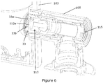
- Figure 6 shows a modification that allows the installer to changeover the inlets 7, 9 without removing the valve assembly 1 from the valve body 103.
- Like reference numerals are used in Figure 6 to indicate parts that are the same or similar to the parts shown in Figures 1 to 5
- incoming supplies of hot and cold water are connected to inlet elbow connectors 105 (one only shown).
- Each connector 105 is similar and the following description of the connector 105 associated with the inlet adaptor member 33 will be understood to apply to the other connector associated with the inlet adaptor member 35.
- the inlet elbow connector 105 has an internal actuator member 113 that is operatively connected to the inlet adaptor member 33.
- the actuator member 113 may have a drive formation 113a, for example a projection such as a rib, and the inlet adaptor member 33 may have a coupling formation 33b, for example a recess such as a groove, engaged by the drive formation.
- the inlet adaptor member 33 may be rotated between the first and second positions by removing a detachable end cap (not shown) and inserting a tool into the open end 115 of the inlet elbow connector 105 to operate the actuator member 113.
- End stops may be provided to limit rotation of the actuator member 113 and define the first and second positions of the inlet adaptor member 33.
- Markers may be provided to indicate the configuration of the inlet 7 in each end position of the adaptor member 33.
- the end positions may be designated hot or cold by any suitable means such as by colour, for example red for hot and blue for cold and/or by one or more letters, for example "H" for hot and "C” for cold.
- the other inlet elbow connector has a similar arrangement for rotating the inlet adaptor member 35.
- the internal actuator member 113 is a chassis or sleeve but may take different forms in other embodiments.
- the inlet adaptor members 33, 35 could be mounted in an housing and rotated with a screw driver or other suitable tool.
- the angular spacing between the end positions of the inlet adaptor members 33, 35 is 180 degrees. This may not be essential and in other embodiments the angular spacing may be more than or less than 180 degrees.
- valve assembly 1 a modification of the valve assembly 1 is shown in which like reference numerals in the series are used to indicate corresponding parts.
- valve cartridge body 3 receives a valve cartridge (not shown) as described above and has inlets 7, 9 for connection to supplies of hot and cold water and an outlet 11 for connection to a supply fitting such as a shower spray head or shower handset.
- Each inlet 7, 9 has two openings or ports 7a, 7b, 9a, 9b which, in this embodiment are of elliptical shape although this is not essential and the openings 7a, 7b, 9a, 9b may have other shapes.
- the openings 7a, 9a open to the cold side of the valve cartridge and the openings 7b, 9b open to the hot side of the valve cartridge.
- the inlets 7, 9 are provided with inlet adaptor members 33, 35 by means of which the inlets 7, 9 can be configured to communicate with the hot side or the cold side of the valve cartridge 5.
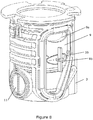
- Figure 7 shows the inlet 7 configured for connection to the hot side of the valve cartridge through opening 7b by closing opening 7a with the inlet adaptor member 33 and
- Figure 8 shows the inlet 9 configured for connection to the cold side through opening 9a by closing the opening 9b with the inlet adaptor member 35.
- the inlet adaptor members 33, 35 which may take the form of plugs, bungs or the like can be reversed or switched to configure the inlet 7 for connection to the cold side of the valve cartridge through opening 7a by closing opening 7b with the inlet adaptor member 35 and the inlet 9 for connection to the hot side through opening 9b by closing the opening 9a with the inlet adaptor member 33.
- the size and shape of the inlets 7, 9 and the inlet adaptor members 33, 35 is preferably such that the adaptor member 33 can only be fitted in the openings 7a or 9a and the adaptor member 35 can only be fitted in the openings 7b or 9b. This prevents the faucet being assembled with both inlets configured to block flow to the same side of the valve cartridge.
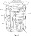
- the size and shape of the inlet adaptor members is preferably such that, when the adaptor member 33 is fitted in the opening 7a of inlet 7, the adaptor member 35 cannot be fitted in the opening 7b.
- the size and shape of the inlet adaptor members is preferably such that, when the adaptor member 35 is fitted in the opening 9b of inlet 9, the adaptor member 33 cannot be fitted in the opening 9a. This prevents the faucet being assembled with both adaptors fitted in the same inlet.
- the inlet adaptors 33, 35 allow the valve assembly 1 to be configured either with inlet 7 designated the “cold” inlet and inlet 9 designated the “hot” inlet or with inlet 9 designated the "cold” inlet and inlet 7 designated the “hot” inlet. In this way the hot and cold designation of each inlet 7, 9 can be switched to match the orientation of the incoming supplies of hot and cold water without changing the installed orientation of the valve assembly 1.
- the inlet adaptor members 33, 35 may be made of any suitable material.
- the inlet adaptor members 33, 35 may provide a sealing function and may comprise an elastomeric material which may be over-moulded on a support to provide greater strength and/or location features.
- the valve cartridge 5 is received in the valve cartridge body 3 that is received in the valve body 103. This may not be essential and in other embodiments the valve cartridge body 3 may be omitted and the valve cartridge 5 received in the valve body 103.
Landscapes
- Engineering & Computer Science (AREA)
- Health & Medical Sciences (AREA)
- Life Sciences & Earth Sciences (AREA)
- Hydrology & Water Resources (AREA)
- Public Health (AREA)
- Water Supply & Treatment (AREA)
- Physics & Mathematics (AREA)
- General Physics & Mathematics (AREA)
- Automation & Control Theory (AREA)
- Domestic Plumbing Installations (AREA)
- Multiple-Way Valves (AREA)
Description
- This invention relates to a faucet according to the preamble of
claim 1, and to a method of installing a faucet according to the preamble ofclaim 15. The invention has particular, but not exclusive, application to mixer valves for shower systems. - A shower mixer valve has separate inlets for connection to supplies of hot and cold water and an outlet for connection to a shower head such as a handset or a spray head. When installing the valve, the pipework for the hot and cold supplies must be plumbed into position for connection to the inlets. It is an industry standard in the UK that the hot supply is on the left hand side and the cold supply is on the right hand side and shower mixer valves are configured with the inlets arranged accordingly for connection to the hot and cold supplies.
- A typical shower mixer valve comprises a valve body housing a cartridge designed to mix hot and cold water to provide outlet water having a desired temperature. The cartridge has hot and cold sides separated from one another for receiving hot and cold water from the inlets and this arrangement requires the inlets to be connected to the correct supplies. However, sometimes by mistake or other reason the arrangement of the pipework may be reversed so that the cold supply is on the left hand side and the hot supply is on the right hand side. If the valve is installed with the inlets connected to the wrong supplies, i.e. the cold inlet connected to the hot supply and the hot inlet connected to the cold supply, the valve may not function correctly and/or performance may be impaired.
- One solution to the problem of installing the valve when the arrangement of the pipework is reversed from the industry standard is to provide the valve with two outlets, one on the top and another on the bottom of the valve body. This allows the installer to rotate the whole valve through 180 degrees to connect the inlets to the correct supplies and connect one of the outlets for supplying outlet water to a spray fitting such as a handset or spray head. With this arrangement the outlet that is not used is closed with a blanking plug. This is a relatively simple solution but is not aesthetically pleasing as the blanking plug is always visible.
- Another solution to the problem of installing the valve when the arrangement of the pipework is reversed from the industry standard is to remove the cartridge from the valve body, turn the cartridge through 180 degrees and re-insert the cartridge in the valve body to connect the inlets to the correct side of the cartridge. Such an arrangement is described in Applicants earlier UK Patent
2291693B -
DE3643528A1 describes a device for the wall connection of a mixer unit with reverse arranged hot and cold water supply lines in order to produce a standard connection gauge for sanitary mixer units. For each of the hot and cold water supply lines, a first angle piece can be connected to a connection piece and can be joined to a second angle piece, exhibiting a connection opening for the mixer unit. - This document is selected as representing the closest prior art.
-
GB1441243A -
GB2340210A valve member 35 is axially movable between a cold seat and a hot seat to control and regulate mixing of hot and cold water in accordance with adjustable selection of outlet water temperature. -
WO02/46853A1 -
WO2010038036A1 describes a mixing valve having a pair of inlet connector assemblies that are operable to connect the mixing valve to supply pipes for hot and cold water. The connector assemblies are adjustable to enable the mixing valve to be connected to the supply pipes to compensate for variations in one or more of the spacing, depth and angular position of the supply pipes. -
EP1672257A1 describes a thermostatic mixing vale for hot and cold water having a valve member axially movable between opposed hot and cold seats to vary the relative proportions of hot and cold water admitted to a mixing chamber according to user selection of a desired water temperature and a thermostat responsive to the mixed water temperature to adjust the position of the valve member to maintain constant the selected water temperature. The valve member is biased by a return spring in the form of a wave spring having a plurality of turns with transverse waves configured such that adjacent turns sit peak to peak. The wave spring is strong in compression and weak in torsion allowing the ends of the spring to move laterally to accommodate any misalignment in the components of the valve. - The faucet has a hot water side fitting leg forming a hot water stream way, a water side fitting leg forming a cold water stream way, a hot water receiving passage, and a cold water receiving passage. The faucet also has a base seat installed on a faucet fitting face, and a faucet body having a hot water introduction passage, and a cold water introduction passage. The base seat has a bottom face in which a hot water side connection opening to which the hot water side fitting leg is connected communicates with a first hole, and in which a cold water side connection opening to which the cold water side fitting leg is connected communicates with a second hole. Moreover at least two sets of the hot water side connection opening and the cold water side connection opening are provided.
- According to a first aspect of the invention, there is provided a faucet having a valve for mixing hot and cold water, the valve having a hot side for receiving hot water and a cold side for receiving cold water, a first inlet with an inlet adaptor for connecting a first supply of water to one of the hot side and the cold side of the valve, and a second inlet with an inlet adaptor for connecting a second supply of water to the other of the hot side and the cold side of the valve, wherein each inlet communicates with both the hot side and cold side of the valve and the associated inlet adaptor is arranged to permit fluid flow to one side and to block fluid flow to the other side.
- The inlet adaptors allow the faucet to be configured with the inlet adaptors either connecting the first inlet to the cold side and the second inlet to the hot side or connecting the first inlet to the hot side and the second inlet to the cold side. In this way, the inlets can be configured for connecting a supply of cold water to the cold side of the valve or a supply of hot water to the hot side of the valve for connecting the hot and cold sides of the valve to the correct supply of hot and cold water by means of the inlet adaptors.
- It may be that each inlet has an opening to the hot side and another opening to the cold side of the valve wherein one of the openings is closed by the inlet adaptor to block fluid flow to one side of the valve and the other opening is open to permit fluid flow to the other side of the valve.
- In one arrangement, the inlet adaptors comprise members that can be fitted in the inlet openings to block fluid flow. It may be that the members are configured so that only one member can be fitted in each inlet to close the opening to either the hot side or the cold side of the valve. In this way the faucet cannot be installed with both openings associated with an inlet closed to prevent fluid flow to both the hot and cold sides of the valve.
- It may be that two members are provided, one member being configured to close an opening to the cold side of the valve and the other member being configured to close an opening to the hot side of the valve. The members may be distinguished by size and/or shape and/or colour. In this way, the member for closing an opening to the cold side of the valve can be installed in one of the inlets and the member for closing an opening to the hot side of the valve can be installed in the other inlet and the installation of the members can be reversed to configure the inlets according to whether the supply of water connected to the inlet is hot water or cold water.
- It may be that, the openings and/or members are configured so that the member for closing an opening to the hot side of the valve cannot be installed in an opening to the cold side of the valve, and the member for closing an opening to the cold side of the valve cannot be installed in an opening to the hot side of the valve. In this way the faucet cannot be installed with openings to the same side of the valve blocked.
- In another arrangement, the inlet adaptors comprise members having a first position in which fluid flow to the cold side of the valve is blocked and fluid flow to the hot side of the valve is permitted and a second position in which fluid flow to the cold side of the valve is permitted and fluid flow to the hot side of the valve is blocked. In this way, the one inlet provides fluid flow to the cold side of the valve when the associated inlet adaptor is in the second position and the other inlet provides fluid flow to the hot side of the valve when the associated inlet adaptor is in the first position.
- It may be that each inlet adaptor has a solid portion blocking fluid flow and an apertured portion permitting fluid flow. It may be that the apertured portion comprises one or more apertures. It may be that in the first position, the solid portion blocks the opening to the cold side of the valve and the apertured portion aligns with the opening to the hot side of the valve. It may be that in the second position, the solid portion blocks the opening to the hot side of the valve and the apertured portion aligns with the opening to the cold side of the valve.
- It may be that each inlet adaptor can be switched between the first and second positions for reversing the hot and cold water connections to the valve. It may be that each inlet includes an actuator for manually switching the associated inlet adaptor between the first and second positions. It may be that the inlet adaptors are rotatable between the first and second positions. It may be that the first and second positions correspond to rotation of the inlet adaptors through 180 degrees. It may be that each inlet includes a marker for providing a visual indication of the position of the associated inlet adaptor.
- According to a second aspect of the invention, there is provided a method of installing a faucet having a valve for mixing hot and cold water, the method including the steps of providing a first inlet with an inlet adaptor for connecting a first supply of water to one of a hot side, for receiving hot water, and a cold side, for receiving cold water, of the valve, and a second inlet with an inlet adaptor for connecting a second supply of water to the other of the hot side and cold side of the valve, and configuring the inlet adaptors for connecting the hot and cold sides of the valve to the correct supplies, wherein each inlet communicates with both the hot side and cold side of the valve and the associated inlet adaptor is arranged to permit fluid flow to one side and to block fluid flow to the other.
- The inlet adaptors allow the faucet to be configured with the inlet adaptors arranged either for connecting the first inlet to the cold side and the second inlet to the hot side or for connecting the first inlet to the hot side and the second inlet to the cold side. In this way, the inlets can be reversed for connecting the hot and cold sides of the valve to the correct supply by setting the inlet adaptors according to whether the incoming supplies are hot or cold water.
- The inlet adaptors may comprise any of the features of the first aspect of the invention.
- The invention will now be described in more detail by way of example only with reference to the accompanying drawings wherein:
-
Figure 1 is a sectional view of a valve assembly according to the invention with the inlet adaptors in a first configuration; -
Figure 2 is a perspective view from one side of the valve body shown inFigure 1 ; -
Figure 3 is a sectional view, similar toFigure 1 , with the inlet adaptors in a second configuration; -
Figure 4 is a perspective view from one side of the valve body shown inFigure 3 ; -
Figure 5 is a perspective view of a shower mixer valve; -
Figure 6 is a sectional view of a modification to the valve assembly shown inFigures 1 to 4 ; -
Figure 7 is a perspective view from one side showing a modification to the valve assembly offigures 1 to 4 ; -
Figure 8 is a perspective view from the other side of the modification ofFigure 7 ; and -
Figures 9 and10 are perspective views showing the relationship between the inlet adaptors. - Referring first to
Figures 1 to 4 , avalve assembly 1 is shown having avalve cartridge body 3 and avalve cartridge 5 received in thevalve cartridge body 3. Thevalve cartridge body 3 hasinlets outlet 11 for connection to a supply fitting such as shower spray head or shower handset. The supplies of hot and cold water flow from theinlets valve cartridge 5 to theoutlet 11. - Within the
valve cartridge 5, the supplies of hot and cold water can be mixed to provide a source of blended water at theoutlet 11 having a desired temperature according to user selection. Thevalve cartridge 5 may comprise a shuttle valve having a valve member movable between hot and cold seats to control the relative proportions of hot and cold water admitted to a mixing chamber where the water is mixed to provide the user selected temperature at theoutlet 11. Thevalve cartridge 5 may be arranged to allow the user to select outlet water temperature from full cold through to full hot. - The
valve cartridge 5 may be thermostatic with asensor 13, for example a thermostat, for monitoring the water temperature in the mixing chamber, and the shuttle valve may be responsive to a detected change in outlet water temperature from that selected, for example due to changes in the temperature and/or pressure of one or both inlet supplies, to adjust the relative proportions of hot and cold water to return the outlet water temperature to that selected by the user. In other embodiments, thevalve cartridge 5 may be non-thermostatic. - The
valve cartridge 5 may be a push fit in thevalve cartridge body 3 through anopening 15 at one end of thevalve cartridge body 3. Thevalve cartridge body 3 has aninternal bore 17 leading from theopening 15 to the other end of thevalve cartridge body 3. Theinternal bore 17 is closed at the other end of thevalve cartridge body 3 by anend cap 19. In other embodiments (not shown), theend cap 19 may be omitted and theinternal bore 17 closed by an end wall integral with thevalve cartridge body 3. - The
internal bore 17 is provided with three axially spaced annular sealing faces 21, 23, 25 and thevalve cartridge 5 is provided with three axially spaced annular sealingmembers - The sealing faces 21, 23, 25 are arranged coaxially and reduce in diameter in the direction of insertion of the
valve cartridge 5 from the sealingface 21 to the sealingface 25. The sealingmembers valve cartridge 5 from the sealingmember 27 to the sealingmember 31. - The progressive change in diameter of the sealing faces 21, 23, 25 within the
internal bore 17 and sealingmembers valve cartridge 5 may be advantageous when inserting thevalve cartridge 5 into thevalve cartridge body 3 and/or removing thevalve cartridge 5 from thevalve cartridge body 3. Thus the force to insert/remove thevalve cartridge 5 may be reduced and/or damage to the sealingmembers members - The
valve cartridge 5 has a hot side for connection to the incoming supply of hot water and a cold side for connection to the incoming supply of cold water. The hot side and cold side are separated by engagement of the sealingmember 29 with the sealingface 23. In this embodiment, the cold side is positioned in the area between the sealingmember 27 and the sealingmember 29, and the hot side is positioned in the area between the sealingmember 29 and the sealingmember 31. The hot side and cold side may be reversed in other embodiments. - Each
inlet inlet adaptor member inlet valve cartridge 5. Theinlet adaptor members valve assembly 1 to be configured either withinlet 7 designated the "cold" inlet andinlet 9 designated the "hot" inlet or withinlet 9 designated the "cold" inlet andinlet 7 designated the "hot" inlet. In this way the hot and cold designation of eachinlet valve assembly 1. - A first configuration of the
inlet adaptor members Figures 1 and 2 with theinlet 7 configured as the "cold" inlet for connection to the cold supply and theinlet 9 configured as the "hot" inlet for connection to the hot supply. A second configuration of theinlet adaptor members Figures 3 and 4 with theinlet 7 configured as the "hot" inlet for connection to the hot supply and theinlet 9 configured as the "cold" inlet for connection to the cold supply. - In the first configuration (
Figures 1 and 2 ), theinlet adaptor member 33 configures theinlet 7 to connect the cold side of thevalve cartridge 5 to the incoming supply of cold water through one ormore apertures 33a in theinlet adaptor member 33 and blocks flow of cold water to the hot side of thevalve cartridge 5, and theinlet adaptor member 35 configures theinlet 9 to connect the hot side of thevalve cartridge 5 to the incoming supply of hot water through one ormore apertures 35a in theinlet adaptor member 35 and blocks flow of hot water to the cold side of thevalve cartridge 5. - In the second configuration (
Figures 3 and 4 ), theinlet adaptor member 33 configures theinlet 7 to connect the hot side of thevalve cartridge 5 to the incoming supply of hot water through the one ormore apertures 33a and blocks flow of hot water to the cold side of thevalve cartridge 5, and theinlet adaptor member 35 configures theinlet 9 to connect the cold side of thevalve cartridge 5 to the incoming supply of cold water through the one ormore apertures 35a and blocks flow of cold water to the hot side of thevalve cartridge 5. - In this embodiment, the
inlet adaptor members annular openings valve cartridge body 3. Eachopening valve cartridge 5 on opposite sides of the sealingmember 29. A portion of eachadaptor member more apertures adaptor member - When the
adaptor members openings valve cartridge body 5 in the first configuration (Figures 1 and 2 ), the apertured portion of theadaptor member 33 connects the cold side of thevalve cartridge 5 to theinlet 7 and the solid portion isolates the hot side from theinlet 7, and the apertured portion of theadaptor member 35 connects the hot side of thevalve cartridge 5 to theinlet 9 and the solid portion isolates the cold side from theinlet 9. - The configuration of the
adaptor members adaptor members openings valve cartridge body 5 in the second configuration (Figures 3 and 4 ), the apertured portion of theadaptor member 33 connects the hot side of thevalve cartridge 5 to theinlet 7 and the solid portion isolates the cold side from theinlet 7, and the apertured portion of theadaptor member 35 connects the cold side of thevalve cartridge 5 to theinlet 9 and the solid portion isolates the hot side from theinlet 9. - The
adaptor members openings adaptor members adaptor members adaptor members adaptor members valve cartridge 5 can be prevented. - Referring now to
Figure 5 , a shower mixer valve 101 is shown having acylindrical body 103 withinlet elbow connectors body 103, and arotatable control knob 109 is arranged at the front end of thebody 103 for user selection of outlet water temperature. - The shower mixer valve 101 may be provided with the
valve assembly 1 ofFigures 1 to 4 received in thevalve body 103 and theinlet adaptors inlet elbow connector 105 connected to the supply pipe for cold water and theinlet elbow connector 107 connected to the supply pipe for hot water. - If, however, the supply pipes are reversed, the installer can remove the
valve assembly 1 from thevalve body 103, remove and re-fit theinlet adaptors inlets inlet adaptors inlet elbow connector 105 to the supply pipe for hot water and theinlet elbow connector 107 to the supply pipe for cold water. The installer can then re-fit thevalve assembly 1 in thevalve body 103 so that theinlet elbow connectors - It will be understood that the invention is not limited to shower mixer valves of the type shown in
Figure 5 and that the invention may be employed in any shower mixer valve where the valve is connected to supplies of hot and cold water. - In the embodiment shown in
Figures 1 to 4 , the installer has to remove and re-fit thevalve assembly 1 when it is required to changeover theinlets inlet 7 being the cold inlet andinlet 9 being the hot inlet toinlet 7 being the hot inlet andinlet 9 being the cold inlet and vice versa. -
Figure 6 shows a modification that allows the installer to changeover theinlets valve assembly 1 from thevalve body 103. Like reference numerals are used inFigure 6 to indicate parts that are the same or similar to the parts shown inFigures 1 to 5 - In the modification of
Figure 6 , incoming supplies of hot and cold water are connected to inlet elbow connectors 105 (one only shown). Eachconnector 105 is similar and the following description of theconnector 105 associated with theinlet adaptor member 33 will be understood to apply to the other connector associated with theinlet adaptor member 35. Theinlet elbow connector 105 has aninternal actuator member 113 that is operatively connected to theinlet adaptor member 33. For example theactuator member 113 may have adrive formation 113a, for example a projection such as a rib, and theinlet adaptor member 33 may have acoupling formation 33b, for example a recess such as a groove, engaged by the drive formation. Theinlet adaptor member 33 may be rotated between the first and second positions by removing a detachable end cap (not shown) and inserting a tool into theopen end 115 of theinlet elbow connector 105 to operate theactuator member 113. End stops may be provided to limit rotation of theactuator member 113 and define the first and second positions of theinlet adaptor member 33. Markers may be provided to indicate the configuration of theinlet 7 in each end position of theadaptor member 33. For example the end positions may be designated hot or cold by any suitable means such as by colour, for example red for hot and blue for cold and/or by one or more letters, for example "H" for hot and "C" for cold. The other inlet elbow connector has a similar arrangement for rotating theinlet adaptor member 35. In this embodiment, theinternal actuator member 113 is a chassis or sleeve but may take different forms in other embodiments. For example theinlet adaptor members inlet adaptor members - Referring now to
Figures 7 to 10 , a modification of thevalve assembly 1 is shown in which like reference numerals in the series are used to indicate corresponding parts. - In this modification, the
valve cartridge body 3 receives a valve cartridge (not shown) as described above and hasinlets outlet 11 for connection to a supply fitting such as a shower spray head or shower handset. - Each
inlet ports openings openings openings - The
inlets inlet adaptor members inlets valve cartridge 5. -
Figure 7 shows theinlet 7 configured for connection to the hot side of the valve cartridge throughopening 7b by closingopening 7a with theinlet adaptor member 33 andFigure 8 shows theinlet 9 configured for connection to the cold side throughopening 9a by closing theopening 9b with theinlet adaptor member 35. - The
inlet adaptor members inlet 7 for connection to the cold side of the valve cartridge throughopening 7a by closingopening 7b with theinlet adaptor member 35 and theinlet 9 for connection to the hot side throughopening 9b by closing theopening 9a with theinlet adaptor member 33. - As shown in
Figures 7 and8 , the size and shape of theinlets inlet adaptor members adaptor member 33 can only be fitted in theopenings adaptor member 35 can only be fitted in theopenings - As shown in
Figure 9 , the size and shape of the inlet adaptor members is preferably such that, when theadaptor member 33 is fitted in theopening 7a ofinlet 7, theadaptor member 35 cannot be fitted in theopening 7b. Similarly, as shown inFigure 10 , the size and shape of the inlet adaptor members is preferably such that, when theadaptor member 35 is fitted in theopening 9b ofinlet 9, theadaptor member 33 cannot be fitted in theopening 9a. This prevents the faucet being assembled with both adaptors fitted in the same inlet. - As will be appreciated, the
inlet adaptors valve assembly 1 to be configured either withinlet 7 designated the "cold" inlet andinlet 9 designated the "hot" inlet or withinlet 9 designated the "cold" inlet andinlet 7 designated the "hot" inlet. In this way the hot and cold designation of eachinlet valve assembly 1. - In the embodiments described, the
inlet adaptor members inlet adaptor members valve cartridge 5 is received in thevalve cartridge body 3 that is received in thevalve body 103. This may not be essential and in other embodiments thevalve cartridge body 3 may be omitted and thevalve cartridge 5 received in thevalve body 103. - Although the invention has been described in the exemplary embodiments with reference to shower mixer valves, it will be understood that the invention has wider application to any faucet for mixing two fluids.
Claims (15)
- A faucet having a valve for mixing hot and cold water, the valve having a hot side for receiving hot water and a cold side for receiving cold water, a first inlet (7) with an inlet adaptor (33) for connecting a first supply of water to one of the hot side and the cold side of the valve, and a second inlet (9) with an inlet adaptor (35) for connecting a second supply of water to the other of the hot side and the cold side of the valve, characterised in that each inlet (7, 9) communicates with both the hot side and cold side of the valve and the associated inlet adaptor (33, 35) is arranged to permit fluid flow to one side and to block fluid flow to the other side.
- The faucet of claim 1 wherein the inlet adaptors (33, 35) can be configured to selectively connect either the first inlet (7) to the cold side and the second inlet (9) to the hot side or the first inlet (7) to the hot side and the second inlet (9) to the cold side.
- The faucet of any preceding claim wherein each inlet (7, 9) has an opening to the hot side (7b, 9b) and another opening (7a, 9a) to the cold side of the valve wherein one of the openings (7a, 7b, 9a, 9b) is closed by the inlet adaptor (33, 35) to block fluid flow to one side of the valve and the other opening (7a, 7b, 9a, 9b) is open to permit fluid flow to the other side of the valve.
- The faucet according to claim 3 wherein the inlet adaptors (33, 35) comprise members (33, 35) that can be fitted in the inlet openings (37, 39) to block fluid flow.
- The faucet of claim 4 wherein the members (33, 35) are configured so that only one member (33, 35) can be fitted in each inlet (7, 9) to close the opening (37, 39) to either the hot side or the cold side of the valve.
- The faucet of claim 4 or claim 5 wherein two members (33, 35) are provided, one member (33, 35) being configured to close an opening (7a, 9a) to the cold side of the valve and the other member (33, 35) being configured to close an opening (7b, 9b) to the hot side of the valve.
- The faucet of any of claims 4 to 6 wherein the members (33, 35) are distinguished by size and/or shape and/or colour.
- The faucet of any of claims 4 to 7 wherein the openings (37, 39) and/or members (33, 35) are configured so that the member (33, 35) for closing an opening (7b, 9b) to the hot side of the valve cannot be installed in an opening (7a, 9a) to the cold side of the valve, and the member (33, 35) for closing an opening (7a, 9a) to the cold side of the valve cannot be installed in an opening (7b, 9b) to the hot side of the valve.
- The faucet of any of claims 1 to 3 wherein the inlet adaptors (33, 35) comprise members (33, 35) having a first position in which fluid flow to the cold side of the valve is blocked and fluid flow to the hot side of the valve is permitted and a second position in which fluid flow to the cold side of the valve is permitted and fluid flow to the hot side of the valve is blocked.
- The faucet of claim 9 wherein each inlet adaptor (33, 35) has a solid portion blocking fluid flow and an apertured portion (33a, 35a) permitting fluid flow.
- The faucet of claim 9 or claim 10 wherein each inlet adaptor (33, 35) can be switched between the first and second positions for reversing the hot and cold water connections to the valve.
- The faucet of claim 11 wherein each inlet (7, 9) includes an actuator (113) for manually switching the associated inlet adaptor (33, 35) between the first and second positions.
- The faucet of claim 12 wherein the inlet adaptors (33, 35) are rotatable between the first and second positions, optionally wherein the first and second positions correspond to rotation of the inlet adaptors (33, 35) through 180 degrees.
- The faucet of any of claims 9 to 13 wherein each inlet (7, 9) includes a marker for providing a visual indication of the position of the associated inlet adaptor (33, 35).
- A method of installing a faucet having a valve for mixing hot and cold water, the method including the steps of providing a first inlet (7) with an inlet adaptor (33) for connecting a first supply of water to one of a hot side, for receiving hot water, and a cold side, for receiving cold water, of the valve, and a second inlet (9) with an inlet adaptor (35) for connecting a second supply of water to the other of the hot side and cold side of the valve, and configuring the inlet adaptors (33, 35) for connecting the hot and cold sides of the valve to the correct supplies, characterised in that each inlet (7, 9) communicates with both the hot side and cold side of the valve and the associated inlet adaptor (33, 35) is arranged to permit fluid flow to one side and to block fluid flow to the other.
Applications Claiming Priority (2)
| Application Number | Priority Date | Filing Date | Title |
|---|---|---|---|
| GB1522322.5A GB2545471A (en) | 2015-12-17 | 2015-12-17 | Plumbing fixtures |
| PCT/GB2016/053807 WO2017103567A1 (en) | 2015-12-17 | 2016-12-02 | Plumbing fixtures |
Publications (2)
| Publication Number | Publication Date |
|---|---|
| EP3390733A1 EP3390733A1 (en) | 2018-10-24 |
| EP3390733B1 true EP3390733B1 (en) | 2019-06-26 |
Family
ID=55311172
Family Applications (1)
| Application Number | Title | Priority Date | Filing Date |
|---|---|---|---|
| EP16808781.5A Active EP3390733B1 (en) | 2015-12-17 | 2016-12-02 | Plumbing fixtures |
Country Status (3)
| Country | Link |
|---|---|
| EP (1) | EP3390733B1 (en) |
| GB (1) | GB2545471A (en) |
| WO (1) | WO2017103567A1 (en) |
Family Cites Families (9)
| Publication number | Priority date | Publication date | Assignee | Title |
|---|---|---|---|---|
| GB1441243A (en) * | 1973-01-15 | 1976-06-30 | Barking Brassware | Mixer valves |
| DE3643528A1 (en) * | 1986-12-19 | 1988-06-30 | Grohe Armaturen Friedrich | Connection device for sanitary fittings |
| GB2311589B (en) * | 1996-03-27 | 2000-06-07 | Caradon Mira Ltd | Improvements in or relating to mixing valves |
| US7073725B2 (en) * | 2000-12-06 | 2006-07-11 | Valquest Limited | Flow mixer |
| JP4081313B2 (en) * | 2002-07-01 | 2008-04-23 | 株式会社三栄水栓製作所 | Hot and cold water faucet |
| GB0413672D0 (en) * | 2004-06-18 | 2004-07-21 | Kohler Mira Ltd | Improvements in or relating to ablutionary installations |
| GB0427420D0 (en) * | 2004-12-15 | 2005-01-19 | Kohler Mira Ltd | Improvements in or relating to thermostatic mixing valves |
| GB2463936B (en) * | 2008-10-02 | 2012-04-18 | Kohler Mira Ltd | Fluid connector |
| GB0818002D0 (en) * | 2008-10-02 | 2008-11-05 | Kohler Mira Ltd | Improvements in or relating to ablutionary installations |
-
2015
- 2015-12-17 GB GB1522322.5A patent/GB2545471A/en not_active Withdrawn
-
2016
- 2016-12-02 EP EP16808781.5A patent/EP3390733B1/en active Active
- 2016-12-02 WO PCT/GB2016/053807 patent/WO2017103567A1/en not_active Ceased
Non-Patent Citations (1)
| Title |
|---|
| None * |
Also Published As
| Publication number | Publication date |
|---|---|
| GB2545471A (en) | 2017-06-21 |
| EP3390733A1 (en) | 2018-10-24 |
| GB201522322D0 (en) | 2016-02-03 |
| WO2017103567A1 (en) | 2017-06-22 |
Similar Documents
| Publication | Publication Date | Title |
|---|---|---|
| US10724649B2 (en) | Mixing valve | |
| US9151025B2 (en) | Fluid delivery assembly (2-in and 1-out, plus quick-connect diverter housing assembly) | |
| US6237622B1 (en) | Flow diverter assembly | |
| CN111226010B (en) | Line Parts and Line Assemblies | |
| US6394133B1 (en) | Faucet with adjustable delivery spout and operating lever | |
| EP0886013A1 (en) | Anti-scald faucet system | |
| US20160305557A1 (en) | Rotary switch valve core | |
| EP3391169B1 (en) | Faucets | |
| RU2114353C1 (en) | Mixing cock valve, spherical valve and spherical valve holder | |
| US20050076960A1 (en) | Mixing faucet | |
| CA3094865C (en) | Mixing valves, valve modules, and valve module assemblies | |
| US6453943B1 (en) | Faucet assembly | |
| JP7403182B2 (en) | flow path switching valve | |
| CN214789184U (en) | A temperature regulating module and faucet | |
| EP1703026A2 (en) | A fluid distribution device | |
| EP3390733A1 (en) | Plumbing fixtures | |
| AU741455B2 (en) | Faucet with adjustable delivery spout and operating lever | |
| CN113396301B (en) | Fluid dispenser unit for sanitary switching accessories | |
| KR100753160B1 (en) | Tee valve | |
| US20120292901A1 (en) | Plumbing fitting | |
| JP2016050408A (en) | Stopcock and faucet device | |
| US20110024663A1 (en) | Fluid flow control apparatus | |
| EP3971461A1 (en) | A connection apparatus | |
| GB2388889A (en) | A hydraulic diverter valve | |
| CA2802804C (en) | Fluid delivery assembly (2-in and 1-out, plus quick-connect diverter housing assembly) |
Legal Events
| Date | Code | Title | Description |
|---|---|---|---|
| STAA | Information on the status of an ep patent application or granted ep patent |
Free format text: STATUS: UNKNOWN |
|
| STAA | Information on the status of an ep patent application or granted ep patent |
Free format text: STATUS: THE INTERNATIONAL PUBLICATION HAS BEEN MADE |
|
| PUAI | Public reference made under article 153(3) epc to a published international application that has entered the european phase |
Free format text: ORIGINAL CODE: 0009012 |
|
| STAA | Information on the status of an ep patent application or granted ep patent |
Free format text: STATUS: REQUEST FOR EXAMINATION WAS MADE |
|
| 17P | Request for examination filed |
Effective date: 20180417 |
|
| AK | Designated contracting states |
Kind code of ref document: A1 Designated state(s): AL AT BE BG CH CY CZ DE DK EE ES FI FR GB GR HR HU IE IS IT LI LT LU LV MC MK MT NL NO PL PT RO RS SE SI SK SM TR |
|
| AX | Request for extension of the european patent |
Extension state: BA ME |
|
| DAV | Request for validation of the european patent (deleted) | ||
| DAX | Request for extension of the european patent (deleted) | ||
| GRAP | Despatch of communication of intention to grant a patent |
Free format text: ORIGINAL CODE: EPIDOSNIGR1 |
|
| STAA | Information on the status of an ep patent application or granted ep patent |
Free format text: STATUS: GRANT OF PATENT IS INTENDED |
|
| INTG | Intention to grant announced |
Effective date: 20190415 |
|
| RIN1 | Information on inventor provided before grant (corrected) |
Inventor name: BUMPSTEED, AUSTIN Inventor name: JONES, OLIVER |
|
| GRAS | Grant fee paid |
Free format text: ORIGINAL CODE: EPIDOSNIGR3 |
|
| GRAA | (expected) grant |
Free format text: ORIGINAL CODE: 0009210 |
|
| STAA | Information on the status of an ep patent application or granted ep patent |
Free format text: STATUS: THE PATENT HAS BEEN GRANTED |
|
| AK | Designated contracting states |
Kind code of ref document: B1 Designated state(s): AL AT BE BG CH CY CZ DE DK EE ES FI FR GB GR HR HU IE IS IT LI LT LU LV MC MK MT NL NO PL PT RO RS SE SI SK SM TR |
|
| REG | Reference to a national code |
Ref country code: GB Ref legal event code: FG4D |
|
| REG | Reference to a national code |
Ref country code: CH Ref legal event code: EP |
|
| REG | Reference to a national code |
Ref country code: AT Ref legal event code: REF Ref document number: 1148439 Country of ref document: AT Kind code of ref document: T Effective date: 20190715 |
|
| REG | Reference to a national code |
Ref country code: DE Ref legal event code: R096 Ref document number: 602016016057 Country of ref document: DE |
|
| REG | Reference to a national code |
Ref country code: IE Ref legal event code: FG4D |
|
| REG | Reference to a national code |
Ref country code: NL Ref legal event code: FP |
|
| PG25 | Lapsed in a contracting state [announced via postgrant information from national office to epo] |
Ref country code: HR Free format text: LAPSE BECAUSE OF FAILURE TO SUBMIT A TRANSLATION OF THE DESCRIPTION OR TO PAY THE FEE WITHIN THE PRESCRIBED TIME-LIMIT Effective date: 20190626 Ref country code: NO Free format text: LAPSE BECAUSE OF FAILURE TO SUBMIT A TRANSLATION OF THE DESCRIPTION OR TO PAY THE FEE WITHIN THE PRESCRIBED TIME-LIMIT Effective date: 20190926 Ref country code: SE Free format text: LAPSE BECAUSE OF FAILURE TO SUBMIT A TRANSLATION OF THE DESCRIPTION OR TO PAY THE FEE WITHIN THE PRESCRIBED TIME-LIMIT Effective date: 20190626 Ref country code: AL Free format text: LAPSE BECAUSE OF FAILURE TO SUBMIT A TRANSLATION OF THE DESCRIPTION OR TO PAY THE FEE WITHIN THE PRESCRIBED TIME-LIMIT Effective date: 20190626 Ref country code: FI Free format text: LAPSE BECAUSE OF FAILURE TO SUBMIT A TRANSLATION OF THE DESCRIPTION OR TO PAY THE FEE WITHIN THE PRESCRIBED TIME-LIMIT Effective date: 20190626 Ref country code: LT Free format text: LAPSE BECAUSE OF FAILURE TO SUBMIT A TRANSLATION OF THE DESCRIPTION OR TO PAY THE FEE WITHIN THE PRESCRIBED TIME-LIMIT Effective date: 20190626 |
|
| REG | Reference to a national code |
Ref country code: LT Ref legal event code: MG4D |
|
| PG25 | Lapsed in a contracting state [announced via postgrant information from national office to epo] |
Ref country code: BG Free format text: LAPSE BECAUSE OF FAILURE TO SUBMIT A TRANSLATION OF THE DESCRIPTION OR TO PAY THE FEE WITHIN THE PRESCRIBED TIME-LIMIT Effective date: 20190926 Ref country code: LV Free format text: LAPSE BECAUSE OF FAILURE TO SUBMIT A TRANSLATION OF THE DESCRIPTION OR TO PAY THE FEE WITHIN THE PRESCRIBED TIME-LIMIT Effective date: 20190626 Ref country code: RS Free format text: LAPSE BECAUSE OF FAILURE TO SUBMIT A TRANSLATION OF THE DESCRIPTION OR TO PAY THE FEE WITHIN THE PRESCRIBED TIME-LIMIT Effective date: 20190626 Ref country code: GR Free format text: LAPSE BECAUSE OF FAILURE TO SUBMIT A TRANSLATION OF THE DESCRIPTION OR TO PAY THE FEE WITHIN THE PRESCRIBED TIME-LIMIT Effective date: 20190927 |
|
| REG | Reference to a national code |
Ref country code: AT Ref legal event code: MK05 Ref document number: 1148439 Country of ref document: AT Kind code of ref document: T Effective date: 20190626 |
|
| PG25 | Lapsed in a contracting state [announced via postgrant information from national office to epo] |
Ref country code: RO Free format text: LAPSE BECAUSE OF FAILURE TO SUBMIT A TRANSLATION OF THE DESCRIPTION OR TO PAY THE FEE WITHIN THE PRESCRIBED TIME-LIMIT Effective date: 20190626 Ref country code: AT Free format text: LAPSE BECAUSE OF FAILURE TO SUBMIT A TRANSLATION OF THE DESCRIPTION OR TO PAY THE FEE WITHIN THE PRESCRIBED TIME-LIMIT Effective date: 20190626 Ref country code: EE Free format text: LAPSE BECAUSE OF FAILURE TO SUBMIT A TRANSLATION OF THE DESCRIPTION OR TO PAY THE FEE WITHIN THE PRESCRIBED TIME-LIMIT Effective date: 20190626 Ref country code: CZ Free format text: LAPSE BECAUSE OF FAILURE TO SUBMIT A TRANSLATION OF THE DESCRIPTION OR TO PAY THE FEE WITHIN THE PRESCRIBED TIME-LIMIT Effective date: 20190626 Ref country code: SK Free format text: LAPSE BECAUSE OF FAILURE TO SUBMIT A TRANSLATION OF THE DESCRIPTION OR TO PAY THE FEE WITHIN THE PRESCRIBED TIME-LIMIT Effective date: 20190626 Ref country code: PT Free format text: LAPSE BECAUSE OF FAILURE TO SUBMIT A TRANSLATION OF THE DESCRIPTION OR TO PAY THE FEE WITHIN THE PRESCRIBED TIME-LIMIT Effective date: 20191028 |
|
| PG25 | Lapsed in a contracting state [announced via postgrant information from national office to epo] |
Ref country code: SM Free format text: LAPSE BECAUSE OF FAILURE TO SUBMIT A TRANSLATION OF THE DESCRIPTION OR TO PAY THE FEE WITHIN THE PRESCRIBED TIME-LIMIT Effective date: 20190626 Ref country code: IS Free format text: LAPSE BECAUSE OF FAILURE TO SUBMIT A TRANSLATION OF THE DESCRIPTION OR TO PAY THE FEE WITHIN THE PRESCRIBED TIME-LIMIT Effective date: 20191026 Ref country code: IT Free format text: LAPSE BECAUSE OF FAILURE TO SUBMIT A TRANSLATION OF THE DESCRIPTION OR TO PAY THE FEE WITHIN THE PRESCRIBED TIME-LIMIT Effective date: 20190626 Ref country code: ES Free format text: LAPSE BECAUSE OF FAILURE TO SUBMIT A TRANSLATION OF THE DESCRIPTION OR TO PAY THE FEE WITHIN THE PRESCRIBED TIME-LIMIT Effective date: 20190626 |
|
| PG25 | Lapsed in a contracting state [announced via postgrant information from national office to epo] |
Ref country code: TR Free format text: LAPSE BECAUSE OF FAILURE TO SUBMIT A TRANSLATION OF THE DESCRIPTION OR TO PAY THE FEE WITHIN THE PRESCRIBED TIME-LIMIT Effective date: 20190626 |
|
| PG25 | Lapsed in a contracting state [announced via postgrant information from national office to epo] |
Ref country code: DK Free format text: LAPSE BECAUSE OF FAILURE TO SUBMIT A TRANSLATION OF THE DESCRIPTION OR TO PAY THE FEE WITHIN THE PRESCRIBED TIME-LIMIT Effective date: 20190626 Ref country code: PL Free format text: LAPSE BECAUSE OF FAILURE TO SUBMIT A TRANSLATION OF THE DESCRIPTION OR TO PAY THE FEE WITHIN THE PRESCRIBED TIME-LIMIT Effective date: 20190626 |
|
| PG25 | Lapsed in a contracting state [announced via postgrant information from national office to epo] |
Ref country code: IS Free format text: LAPSE BECAUSE OF FAILURE TO SUBMIT A TRANSLATION OF THE DESCRIPTION OR TO PAY THE FEE WITHIN THE PRESCRIBED TIME-LIMIT Effective date: 20200320 |
|
| REG | Reference to a national code |
Ref country code: DE Ref legal event code: R097 Ref document number: 602016016057 Country of ref document: DE |
|
| PLBE | No opposition filed within time limit |
Free format text: ORIGINAL CODE: 0009261 |
|
| STAA | Information on the status of an ep patent application or granted ep patent |
Free format text: STATUS: NO OPPOSITION FILED WITHIN TIME LIMIT |
|
| PG2D | Information on lapse in contracting state deleted |
Ref country code: IS |
|
| REG | Reference to a national code |
Ref country code: CH Ref legal event code: PL |
|
| 26N | No opposition filed |
Effective date: 20200603 |
|
| REG | Reference to a national code |
Ref country code: BE Ref legal event code: MM Effective date: 20191231 |
|
| PG25 | Lapsed in a contracting state [announced via postgrant information from national office to epo] |
Ref country code: MC Free format text: LAPSE BECAUSE OF FAILURE TO SUBMIT A TRANSLATION OF THE DESCRIPTION OR TO PAY THE FEE WITHIN THE PRESCRIBED TIME-LIMIT Effective date: 20190626 |
|
| PG25 | Lapsed in a contracting state [announced via postgrant information from national office to epo] |
Ref country code: LU Free format text: LAPSE BECAUSE OF NON-PAYMENT OF DUE FEES Effective date: 20191202 |
|
| PG25 | Lapsed in a contracting state [announced via postgrant information from national office to epo] |
Ref country code: CH Free format text: LAPSE BECAUSE OF NON-PAYMENT OF DUE FEES Effective date: 20191231 Ref country code: LI Free format text: LAPSE BECAUSE OF NON-PAYMENT OF DUE FEES Effective date: 20191231 Ref country code: BE Free format text: LAPSE BECAUSE OF NON-PAYMENT OF DUE FEES Effective date: 20191231 |
|
| PGFP | Annual fee paid to national office [announced via postgrant information from national office to epo] |
Ref country code: FR Payment date: 20201210 Year of fee payment: 5 Ref country code: IE Payment date: 20201208 Year of fee payment: 5 |
|
| PGFP | Annual fee paid to national office [announced via postgrant information from national office to epo] |
Ref country code: NL Payment date: 20201214 Year of fee payment: 5 |
|
| PG25 | Lapsed in a contracting state [announced via postgrant information from national office to epo] |
Ref country code: CY Free format text: LAPSE BECAUSE OF FAILURE TO SUBMIT A TRANSLATION OF THE DESCRIPTION OR TO PAY THE FEE WITHIN THE PRESCRIBED TIME-LIMIT Effective date: 20190626 |
|
| PGFP | Annual fee paid to national office [announced via postgrant information from national office to epo] |
Ref country code: DE Payment date: 20201217 Year of fee payment: 5 |
|
| PG25 | Lapsed in a contracting state [announced via postgrant information from national office to epo] |
Ref country code: MT Free format text: LAPSE BECAUSE OF FAILURE TO SUBMIT A TRANSLATION OF THE DESCRIPTION OR TO PAY THE FEE WITHIN THE PRESCRIBED TIME-LIMIT Effective date: 20190626 Ref country code: HU Free format text: LAPSE BECAUSE OF FAILURE TO SUBMIT A TRANSLATION OF THE DESCRIPTION OR TO PAY THE FEE WITHIN THE PRESCRIBED TIME-LIMIT; INVALID AB INITIO Effective date: 20161202 |
|
| PG25 | Lapsed in a contracting state [announced via postgrant information from national office to epo] |
Ref country code: SI Free format text: LAPSE BECAUSE OF FAILURE TO SUBMIT A TRANSLATION OF THE DESCRIPTION OR TO PAY THE FEE WITHIN THE PRESCRIBED TIME-LIMIT Effective date: 20190626 |
|
| PG25 | Lapsed in a contracting state [announced via postgrant information from national office to epo] |
Ref country code: MK Free format text: LAPSE BECAUSE OF FAILURE TO SUBMIT A TRANSLATION OF THE DESCRIPTION OR TO PAY THE FEE WITHIN THE PRESCRIBED TIME-LIMIT Effective date: 20190626 |
|
| REG | Reference to a national code |
Ref country code: DE Ref legal event code: R119 Ref document number: 602016016057 Country of ref document: DE |
|
| REG | Reference to a national code |
Ref country code: NL Ref legal event code: MM Effective date: 20220101 |
|
| PG25 | Lapsed in a contracting state [announced via postgrant information from national office to epo] |
Ref country code: NL Free format text: LAPSE BECAUSE OF NON-PAYMENT OF DUE FEES Effective date: 20220101 |
|
| PG25 | Lapsed in a contracting state [announced via postgrant information from national office to epo] |
Ref country code: IE Free format text: LAPSE BECAUSE OF NON-PAYMENT OF DUE FEES Effective date: 20211202 Ref country code: DE Free format text: LAPSE BECAUSE OF NON-PAYMENT OF DUE FEES Effective date: 20220701 |
|
| PG25 | Lapsed in a contracting state [announced via postgrant information from national office to epo] |
Ref country code: FR Free format text: LAPSE BECAUSE OF NON-PAYMENT OF DUE FEES Effective date: 20211231 |
|
| P01 | Opt-out of the competence of the unified patent court (upc) registered |
Effective date: 20230705 |
|
| PGFP | Annual fee paid to national office [announced via postgrant information from national office to epo] |
Ref country code: GB Payment date: 20241023 Year of fee payment: 9 |