EP3390677B1 - Wastegate component comprising a novel alloy - Google Patents
Wastegate component comprising a novel alloy Download PDFInfo
- Publication number
- EP3390677B1 EP3390677B1 EP16810595.5A EP16810595A EP3390677B1 EP 3390677 B1 EP3390677 B1 EP 3390677B1 EP 16810595 A EP16810595 A EP 16810595A EP 3390677 B1 EP3390677 B1 EP 3390677B1
- Authority
- EP
- European Patent Office
- Prior art keywords
- alloy
- waste gate
- amount
- gate component
- less
- Prior art date
- Legal status (The legal status is an assumption and is not a legal conclusion. Google has not performed a legal analysis and makes no representation as to the accuracy of the status listed.)
- Active
Links
Images

Classifications
-
- C—CHEMISTRY; METALLURGY
- C22—METALLURGY; FERROUS OR NON-FERROUS ALLOYS; TREATMENT OF ALLOYS OR NON-FERROUS METALS
- C22C—ALLOYS
- C22C30/00—Alloys containing less than 50% by weight of each constituent
-
- B—PERFORMING OPERATIONS; TRANSPORTING
- B24—GRINDING; POLISHING
- B24C—ABRASIVE OR RELATED BLASTING WITH PARTICULATE MATERIAL
- B24C1/00—Methods for use of abrasive blasting for producing particular effects; Use of auxiliary equipment in connection with such methods
- B24C1/10—Methods for use of abrasive blasting for producing particular effects; Use of auxiliary equipment in connection with such methods for compacting surfaces, e.g. shot-peening
-
- C—CHEMISTRY; METALLURGY
- C21—METALLURGY OF IRON
- C21D—MODIFYING THE PHYSICAL STRUCTURE OF FERROUS METALS; GENERAL DEVICES FOR HEAT TREATMENT OF FERROUS OR NON-FERROUS METALS OR ALLOYS; MAKING METAL MALLEABLE, e.g. BY DECARBURISATION OR TEMPERING
- C21D9/00—Heat treatment, e.g. annealing, hardening, quenching or tempering, adapted for particular articles; Furnaces therefor
- C21D9/0068—Heat treatment, e.g. annealing, hardening, quenching or tempering, adapted for particular articles; Furnaces therefor for particular articles not mentioned below
-
- C—CHEMISTRY; METALLURGY
- C22—METALLURGY; FERROUS OR NON-FERROUS ALLOYS; TREATMENT OF ALLOYS OR NON-FERROUS METALS
- C22C—ALLOYS
- C22C19/00—Alloys based on nickel or cobalt
- C22C19/03—Alloys based on nickel or cobalt based on nickel
- C22C19/05—Alloys based on nickel or cobalt based on nickel with chromium
-
- C—CHEMISTRY; METALLURGY
- C22—METALLURGY; FERROUS OR NON-FERROUS ALLOYS; TREATMENT OF ALLOYS OR NON-FERROUS METALS
- C22C—ALLOYS
- C22C19/00—Alloys based on nickel or cobalt
- C22C19/03—Alloys based on nickel or cobalt based on nickel
- C22C19/05—Alloys based on nickel or cobalt based on nickel with chromium
- C22C19/051—Alloys based on nickel or cobalt based on nickel with chromium and Mo or W
- C22C19/055—Alloys based on nickel or cobalt based on nickel with chromium and Mo or W with the maximum Cr content being at least 20% but less than 30%
-
- C—CHEMISTRY; METALLURGY
- C22—METALLURGY; FERROUS OR NON-FERROUS ALLOYS; TREATMENT OF ALLOYS OR NON-FERROUS METALS
- C22C—ALLOYS
- C22C19/00—Alloys based on nickel or cobalt
- C22C19/03—Alloys based on nickel or cobalt based on nickel
- C22C19/05—Alloys based on nickel or cobalt based on nickel with chromium
- C22C19/051—Alloys based on nickel or cobalt based on nickel with chromium and Mo or W
- C22C19/056—Alloys based on nickel or cobalt based on nickel with chromium and Mo or W with the maximum Cr content being at least 10% but less than 20%
-
- F—MECHANICAL ENGINEERING; LIGHTING; HEATING; WEAPONS; BLASTING
- F02—COMBUSTION ENGINES; HOT-GAS OR COMBUSTION-PRODUCT ENGINE PLANTS
- F02B—INTERNAL-COMBUSTION PISTON ENGINES; COMBUSTION ENGINES IN GENERAL
- F02B37/00—Engines characterised by provision of pumps driven at least for part of the time by exhaust
- F02B37/12—Control of the pumps
- F02B37/18—Control of the pumps by bypassing exhaust from the inlet to the outlet of turbine or to the atmosphere
-
- F—MECHANICAL ENGINEERING; LIGHTING; HEATING; WEAPONS; BLASTING
- F02—COMBUSTION ENGINES; HOT-GAS OR COMBUSTION-PRODUCT ENGINE PLANTS
- F02B—INTERNAL-COMBUSTION PISTON ENGINES; COMBUSTION ENGINES IN GENERAL
- F02B37/00—Engines characterised by provision of pumps driven at least for part of the time by exhaust
- F02B37/12—Control of the pumps
- F02B37/18—Control of the pumps by bypassing exhaust from the inlet to the outlet of turbine or to the atmosphere
- F02B37/183—Arrangements of bypass valves or actuators therefor
-
- Y—GENERAL TAGGING OF NEW TECHNOLOGICAL DEVELOPMENTS; GENERAL TAGGING OF CROSS-SECTIONAL TECHNOLOGIES SPANNING OVER SEVERAL SECTIONS OF THE IPC; TECHNICAL SUBJECTS COVERED BY FORMER USPC CROSS-REFERENCE ART COLLECTIONS [XRACs] AND DIGESTS
- Y02—TECHNOLOGIES OR APPLICATIONS FOR MITIGATION OR ADAPTATION AGAINST CLIMATE CHANGE
- Y02T—CLIMATE CHANGE MITIGATION TECHNOLOGIES RELATED TO TRANSPORTATION
- Y02T10/00—Road transport of goods or passengers
- Y02T10/10—Internal combustion engine [ICE] based vehicles
- Y02T10/12—Improving ICE efficiencies
Definitions
- the present invention relates to the field of turbochargers, in particular turbochargers for use in internal combustion engines.
- Turbochargers are used to increase combustion air throughput and density, thereby increasing power and efficiency of internal combustion engines.
- the design and function of turbochargers are described in detail in the prior art, for example, U.S. Pat. Nos. 4,705,463 , and 5,399,064 , the disclosures of which are incorporated herein by reference.
- the materials used in the production of turbochargers have to meet stringent performance requirements. For instance, the materials have to be sufficiently corrosion resistant when exposed to exhaust gasses at temperatures of up to about 1050 °C. Furthermore, the materials have to satisfy mechanical requirements, such as strength, toughness, and tribological requirements at these high temperatures. In particular in twin scroll turbo charger designs, the high frequency of exhaust gas pressure changes results in high requirements regarding tensile strength, LCF performance, and tribological properties of the waste gate materials.
- the nickel-chromium alloy Inconel 713C meets these high requirements and is commercially used for wastegate components.
- Inconel 713C has the following representative composition: C 0.2 wt.-%, Mn 1.0 wt.-% max, S 0.015 wt.-% max, Si 1.0 wt.-% max, Cr 11.0-14.0 wt.-%, Mo 3.5-5.5 wt.-%, Ti 0.25-1.25 wt.-%, Al 5.5-6.5 wt.-%, Fe 5.0 wt.-% max, Nb and Ta 1.0-3.0 wt.-%, Ni remainder.
- Inconel 713C is relatively expensive.
- DE 10 2014 001330 A1 discloses a hardening nickel-chromium-cobalt-titanium-aluminum alloy stating that the alloy has good wear resistance, creep strength, corrosion resistance and processability.
- the present invention relates to a waste gate component for a turbo charger and to processes for preparing such a waste gate component.
- the present invention relates to waste gate component for a turbo charger comprising an alloy of the following composition: a) Ni 30 to 42 wt.-%, b) Cr 15 to 28 wt.-%, c) Co 1 to 5 wt.-%, d) Ti 1 to 4 wt.-%, e) optionally one or more elements selected from the group consisting of Mo, Al, Mn, W, Si and Nb, in particular one or more of elements in amounts as follows: Mo 0.5 to 4 wt.-%, Al 0.1 to 2 wt.-%, Mn 0.1 to 3 wt.-%, W 0.1 to 3 wt.-%, Si 0.5 to 4 wt.-%, and Nb 1 to 4 wt.-%, f) optionally other elements, in particular lanthanoids, boron and zirconium, in minor amounts which add up to a total amount of less than 2 wt.-%, g) Fe as balance, but
- the present invention relates to a method for preparing a waste gate component for a turbo charger comprising an alloy of the following composition: a) Ni 30 to 42 wt.-%, b) Cr 15 to 28 wt.-%, c) Co 1 to 5 wt.-%, d) Ti 1 to 4 wt.-%, e) optionally one or more elements selected from the group consisting of Mo, Al, Mn, W, Si and Nb, in particular one or more of elements in amounts as follows: Mo 0.5 to 4 wt.-%, Al 0.1 to 2 wt.-%, Mn 0.1 to 3 wt.-%, W 0.1 to 3 wt.-%, Si 0.5 to 4 wt.-%, and Nb 1 to 4 wt.-%, f) optionally other elements, in particular lanthanoids, boron and zirconium, in minor amounts which add up to a total amount of less than 2 wt.-%, g
- the present invention relates to a method of modifying the surface of a waste gate component for a turbo charger comprising an alloy of the following composition: a) Ni 30 to 42 wt.-%, b) Cr 15 to 28 wt.-%, c) Co 1 to 5 wt.-%, d) Ti 1 to 4 wt.-%, e) optionally one or more elements selected from the group consisting of Mo, Al, Mn, W, Si and Nb, in particular one or more of elements in amounts as follows: Mo 0.5 to 4 wt.-%, Al 0.1 to 2 wt.-%, Mn 0.1 to 3 wt.-%, W 0.1 to 3 wt.-%, Si 0.5 to 4 wt.-%, and Nb 1 to 4 wt.-%, f) optionally other elements, in particular lanthanoids, boron and zirconium, in minor amounts which add up to a total amount of less than 2 wt.-
- the present invention relates to a waste gate component for a turbo charger comprising an alloy of the following composition: a) Ni 30 to 42 wt.-%, b) Cr 15 to 28 wt.-%, c) Co 1 to 5 wt.-%, d) Ti 1 to 4 wt.-%, e) optionally one or more elements selected from the group consisting of Mo, Al, Mn, W, Si and Nb, in particular one or more of elements in amounts as follows: Mo 0.5 to 4 wt.-%, Al 0.1 to 2 wt.-%, Mn 0.1 to 3 wt.-%, W 0.1 to 3 wt.-%, Si 0.5 to 4 wt.-%, and Nb 1 to 4 wt.-%, f) optionally other elements, in particular lanthanoids, boron and zirconium, in minor amounts which add up to a total amount of less than 2 wt.-%, g) Fe as balance
- the alloy according to the first aspect of the invention comprises 30 to 42 wt.-% Ni.
- the alloy comprises 32 to 39 wt.-%, in particular 34 to 38 wt.-%, Ni.
- the alloy further comprises 15 to 28 wt.-% Cr.
- the alloy comprises 17 to 26 wt.-%, in particular 19 to 24 wt.-%, Cr.
- the alloy further comprises 1 to 5 wt.-% Co.
- the alloy comprises 1 to 5 wt.-%, in particular 1.5 to 4.5 wt.-%, Co.
- the alloy further comprises 1 to 5 wt.-% Ti.
- the alloy comprises 1.5 to 3.5 wt.-%, in particular 2.0 to 3.0 wt.-%, Ti.
- Alloys of this type were found to provide a balanced mix of mechanical, tribological, and corrosion-resistance properties required for the use as a waste gate component for a turbo charger.
- the alloy is relatively inexpensive.
- the alloy may optionally contain one or more further elements to adjust its properties.
- the alloy may optionally comprise one or more elements selected from the group consisting of Mo, Al, Mn, W Si and Nb.
- the said elements may be used in the following amounts:
- the alloy may also contain other elements in minor amounts which add up to a total amount of less than 2 wt.-%.
- these other elements will typically be impurities introduced from raw materials or during the preparation of the alloy.
- other elements purposefully added in minor amounts to fine-tune alloy properties are also intended to be included in this definition as long as their total amount, together with the total amount of impurities, is less than 2 wt.-%.
- elements which may be added in minor amounts to fine-tune alloy properties include lanthanoids, boron or zirconium. These elements in combination with the impurities advantageously add up to a total amount of less than 1.5 wt.-%, more specifically less than 1 wt.-%, and in particular less than 0.5 wt.-%.
- the alloy may comprise Nb in an amount of 1 to 4 wt.-%, in particular 1.7 to 2.5 wt.-%, and/or W in an amount of 0.1 to 3 wt.-%, in particular 0.5 to 2.5 wt.-%, and/or Mo in an amount of 0.5 to 4 wt.-%, in particular 1.0 to 3.0 wt.-%, and C in an amount of less than 0.1 wt.-%, in particular in amounts of 0.02 to 0.09 wt.-%.
- Nb, Mo, and W are thought to compete with Cr in the carbide formation.
- Nb, Mo, and/or W are therefore believed to reduce chromium carbide formation.
- the addition of Nb, Mo, and/or W may free up Cr on the alloy surface which then may form chromium oxides when exposed to hot exhaust gasses. Chromium oxide top coats may, in turn, reduce sliding abrasion and improve oxidation resistance.
- the alloy may contain Nb in an amount of 1 to 4 wt.-%, in particular 1.7 to 2.5 wt.-%, Mo in an amount of 0.5 to 4 wt.-%, in particular 1.0 to 3.0 wt.-%, W in an amount of 0.1 to 3 wt.-%, in particular 0.5 to 2.5 wt.-%, and C in an amount of less than 0.1 wt.-%, in particular in an amount of 0.02 to 0.09 wt.-%.
- the alloy may comprise Nb in an amount of 1.7 to 2.5 wt.-%, Mo in an amount of 1.0 to 3.0 wt.-%, W in an amount of 0.5 to 2.5 wt.-%, and C in an amount of 0.02 to 0.09 wt.-%.
- the alloy may also comprise between 0.5 and 10 wt.-% of one or more elements selected from Mn, Al, and Si.
- the alloy comprises Mn in an amount of 0.1 to 3 wt.-%, in particular 0.5 to 2.5 wt.-%, and/or Al in an amount of 0.1 to 2 wt.-%, in particular 0.3 to 0.8 wt.-%, and/or Si in an amount of 0.5 to 4 wt.-%, in particular 0.6 to 2.4 wt.-%, provided that the total amount of these elements add up to 0.5 and 10 wt.-%.
- the alloy may comprise Mn in an amount of 0.5 to 2.5 wt.-%, Al in an amount of 0.3 to 0.8 wt.-%, and Si in an amount of 0.6 to 2.4 wt.-%.
- Mn, Al, and Si are thought to act as deoxidizing elements and may contribute to high temperature strength and toughness.
- Al and Si further increase resistance to scaling and, thus, may improve high temperature corrosion resistance and resistance to wear.
- the invention in particular also relates to a waste gate component for a turbo charger comprising an alloy of the following composition: a) Ni 30 to 42 wt.-%, b) Cr 15 to 28 wt.-%, c) Co 1 to 5 wt.-%, d) Ti 1 to 4 wt.-%, e) optionally one or more elements selected from the group consisting of Mo, Mn, W, and Nb, in particular one or more of elements in amounts as follows: Mo 0.5 to 4 wt.-%, Mn 0.1 to 3 wt.-%, W 0.1 to 3 wt.-%, and Nb 1 to 4 wt.-%, f) A1 and/or Si in an amount of 0.5 to 10 wt.-%, g) optionally other elements, in
- the alloy may comprise 0.5 to 4 wt.-% Mo, 0.1 to 2 wt.-% Al, 0.1 to 3 wt.-% Mn, 0.1 to 3 wt.-% W, 0.5 to 4 wt.-% Si, 1 to 4 wt.-% Nb, and less than 0.1 wt.-% C.
- the alloy may also comprise 1.0 to 3.0 wt.-% Mo, 0.3 to 0.8 wt.-% Al, 0.5 to 2.5 wt.-% Mn, 0.5 to 2.5 wt.-% W, 0.6 to 2.4 wt.-% Si, 1.7 to 2.5 wt.-% Nb, and 0.02 to 0.09 wt.-% C.
- the alloy comprises 34 to 38 wt.-% Ni, 19 to 24 wt.-% Cr, 1.5 to 4.5 wt.-% Co, 2.0 to 3.0 wt.-% Ti, 1.0 to 3.0 wt.-% Mo, 0.3 to 0.8 wt.-% Al, 0.5 to 2.5 wt.-% Mn, 0.5 to 2.5 wt.-% W, 0.6 to 2.4 wt.-% Si, 1.7 to 2.5 wt.-% Nb, and 0.02 to 0.09 wt.-% C.
- all of the above-described alloys advantageously contain less than 0.1 wt.-% C, less than 0.05 wt.-% P, less than 0.05 wt.-% S, and/or less than 0.04 wt.-% N.
- the alloy according to the invention may have good mechanical, chemical, and tribological properties, in particular at high temperatures.
- the alloy may be endowed with excellent Vickers hardness, ultimate tensile strength, elongation, ultimate elongation, yield strength, creep rate, salt water corrosions resistance, and oxidation stability.
- the waste gate components prepared from the alloy may have similar fatigue resistance as a like components prepared from Inconel 713C.
- the fatigue resistance may e.g. be tested by the fatigue resistance test in accordance with VB101 and/or VB102 of the Fraunhofer Institut für Radiofesttechnik und Systemzuverlassmaschine LBF, Darmstadt, Germany, at temperatures of about 950 °C.
- the alloy may further have an austenitic microstructure comprising second phase particles or aggregates of said second phase particles, wherein said particles have an average size of less than about 5 ⁇ m, in particular less than about 2 ⁇ m.
- the average size refers to the average size as measured/determined on the surface of the alloy or as measured/determined on a cutting plane substantially parallel to the surface of the alloy.
- the average grain size may e.g. be determined by using automatic image analysis according to e.g. ASTM E1245 (2008).
- the present invention relates to a method for preparing a waste gate component for a turbo charger comprising an alloy of the following composition: a) Ni 30 to 42 wt.-%, b) Cr 15 to 28 wt.-%, c) Co 1 to 5 wt.-%, d) Ti 1 to 4 wt.-%, e) optionally one or more elements selected from the group consisting of Mo, Al, Mn, W, Si and Nb, in particular one or more of elements in amounts as follows: Mo 0.5 to 4 wt.-%, Al 0.1 to 2 wt.-%, Mn 0.1 to 3 wt.-%, W 0.1 to 3 wt.-%, Si 0.5 to 4 wt.-%, and Nb 1 to 4
- the alloy to be treated according to the above method may be any alloy disclosed in the first aspect of the invention.
- the precipitation hardening according to the above method is advantageously performed for at least about 4 hours, in particular about 6 to about 12 hours, more specifically about 7 to about 9 hours, at about 700 to about 750°C, in particular about 720 to about 730 °C, followed by tempering the alloy for at least about 4 hours, in particular about 6 to about 12 hours, more specifically about 7 to about 9 hours, at about 600 to about 640°C, in particular about 615 to about 625°C.
- These indications of temperature and time may refer to the surface temperature of the tempered alloy workpiece or, in case of very large workpieces where there may exist a temperature gradient between the surface and the core during periods of temperature adjustment, optionally to the temperature of the core or any other location that takes longest to respond to the temperature adjustment.
- the solution heat treatment in the above method is performed at a temperature and for a duration that ensures a substantially homogeneous distribution of the alloying elements in the alloy.
- Suitable conditions may include heating the alloy to above about 950 °C for at least about 1 hour, in particular heating the alloy to about 980 to about 1050 °C for about 3 or more hours.
- the alloy may further be subjected to recrystallization annealing. Recrystallization annealing may be performed for at least about 4 hours, in particular about 6 to about 12 hours, at a temperatures of about 830 to about 890 °C, in particular about 840 to about 880 °C.
- the alloy obtainable by the above described methods of the second aspect of the invention may be characterized by an austenitic microstructure comprising fine second phase particles and improved mechanical properties, in particular improved tensile strength.
- the above-described methods provide waste gate components comprising an alloy having the following composition: a) Ni 30 to 42 wt.-%, b) Cr 15 to 28 wt.-%, c) Co 1 to 5 wt.-%, d) Ti 1 to 4 wt.-%, e) optionally one or more elements selected from the group consisting of Mo, Al, Mn, W, Si and Nb, in particular one or more of elements in amounts as follows: Mo 0.5 to 4 wt.-%, Al 0.1 to 2 wt.-%, Mn 0.1 to 3 wt.-%, W 0.1 to 3 wt.-%, Si 0.5 to 4 wt.-%, and Nb 1 to 4 wt.-%, f) optionally other elements, in particular lanthan
- the present invention relates to a method of modifying the surface of a waste gate component for a turbo charger comprising an alloy of the following composition: a) Ni 30 to 42 wt.-%, b) Cr 15 to 28 wt.-%, c) Co 1 to 5 wt.-%, d) Ti 1 to 4 wt.-%, e) optionally 0.5 to 4 wt.-% Mo, 0.1 to 2 wt.-% Al, 0.1 to 3 wt.-% Mn, 0.1 to 3 wt.-% W, 0.5 to 4 wt.-% Si, 1 to 4 wt.-% Nb, f) optionally other elements, in particular lanthanoids, boron and zirconium, in minor amounts which add up to a total amount of less than 2 wt.-%, g) Fe as balance, but at least in an amount of 20 wt.-%; wherein at least part of the surface of a waste gate
- the alloy to be treated according to the above method may be any alloy disclosed in the first aspect of the invention.
- the method according to the third aspect of the invention modifies the surface of the waste gate component by producing a plurality of surface indentations on the surface of the waste gate component. Examples of such surface indentations are shown in Fig.s 1 and 2 . These surface indentations may have an average depth of about 20 to about 70 ⁇ m, in particular about 25 to about 55 ⁇ m. The average depth of the surface indentations may e.g. be determined by calculating the average depth on basis of about 100 neighbouring indentations. The depth of individual indentations may be determined by optical, spectroscopic or other means.
- the surface indentations may be characterized by a surface roughness, measured according to DIN EN ISO 4287 and/or 4288, as defined by an Rz-value of less than about 25 ⁇ m, in particular less than about 15 ⁇ m, more specifically less than about 10 ⁇ m, or between about 2 and about 25 ⁇ m, more specifically between about 5 and about 15 about 15 ⁇ m.
- the Ra-value may be between about 1 and about 5 ⁇ m, in particular between about 2 and about 4 ⁇ m.
- the plurality of surface indentations may improve the tribological performance of the waste gate component. Since the waste gate components of the turbocharger move or rotate in response to control inputs, an improvement in the tribological performance of its components also reduces the hysteresis of controlling the waste gate. Therefore, a waste gate component wherein at least part of the surface of a waste gate component is shot peened as described above may also have improved control quality.
- the shot peened waste gate component comprises in particular the spindle.
- an alloy of the first aspect of the invention which comprises Nb in an amount of 1 to 4 wt.-%, in particular 1.7 to 2.5 wt.-%, and/or W in an amount of 0.1 to 3 wt.-%, in particular 0.5 to 2.5 wt.-%, and/or Mo in an amount of 0.5 to 4 wt.-%, in particular 1.0 to 3.0 wt.-%, and C in an amount of less than 0.1 wt.-%, in particular in amounts of 0.02 to 0.09 wt.-%.
- Nb, Mo, and/or W may free up Cr on the alloy surface which then may form chromium oxides which may, in turn, reduce sliding abrasion and improve oxidation resistance. Reducing sliding abrasion may further improve control quality. Improving oxidation resistance may help in maintaining the surface quality of the wastegate component for a longer period of time and, thus, may further improve long-term control quality.
- an alloy of the first aspect of the invention which comprises between 0.6 and 6 wt.-% of one or more elements selected from Al and Si.
- the alloy comprises Al in an amount of 0.1 to 2 wt.-%, in particular 0.3 to 0.8 wt.-%, and/or Si in an amount of 0.5 to 4 wt.-%, in particular 0.6 to 2.4 wt.-%.
- the shot peening step according to the above method is advantageously performed with a substantially spherical shot material.
- substantially spherical shot media are commercially available, for instance as conditioned steel cut wire shot.
- Steel cut wire shot is prepared by cutting steel wire into cylindrical grains so that the respective length of the grain is substantially the same as the diameter of the wire. By rounding the cylinder edges a conditioned grain is created, classified in the grain shapes G1 (rounded edges), G2-(almost spherical grain) and G3 (spherical grain).
- a substantially spherical shot material is a G2 and G3-type material.
- the substantially spherical shot material is a G3 conditioned steel cut wire shot material.
- substantially spherical mineralic shot media such as glass or ceramic pearl media.
- the substantially spherical shot material is selected form the group consisting of conditioned steel cut wire shot, glass pearls, ceramic pearls, copper shot, and brass shot.
- the substantially spherical shot material is in particular selected from conditioned steel cut wire shot, fineshot, glass pearls and ceramic pearls.
- the substantially spherical shot material is suitable to deform the surface of the waste gate component and may be harder than said surface.
- the Vickers hardness of the shot peening material may be from about 450 to about 850 HV, in particular from about 670 to about 730 HV.
- the average diameter of the substantially spherical shot material may be between about 100 ⁇ m and about 2000 ⁇ m, more specifically between about 200 and about 800 ⁇ m, in particular about 300 to about 600 ⁇ m.
- the substantially spherical shot material is a conditioned steel cut wire shot media having a Vickers hardness between about 670 to about 730 HV and an average diameter between about 200 and about 800 ⁇ m, in particular about 300 to about 600 ⁇ m.
- a waste gate component according to the invention may be shot peened as follows:
- the waste gate component such as a waste gate spindle is shot peened with an air blast system (e.g. a blast cabinet STD 1400 PS from Rösler Oberflachentechnik GmbH, Germany) using a conditioned steel cut wire shot media having a Vickers hardness between about 670 to about 730 HV and an average diameter between about 400 ⁇ m, using a blasting gun having one air nozzle of about 10 mm diameter and a pressure of about 2 bars.
- the distance between the workpiece and the nozzle is about 80 mm and the nozzle is angled at about 45°.
- the workpiece is rotated at about 48 rpm and the nozzle is moved 4 times over the workpiece at a speed of about 10 mm/sec.
- the shot-peened surface of the waste gate component may optionally be subj ected to one or more further shot peenings.
- a further shot peening may smoothen the edges of the indentation obtained by the first shot peening.
- the one or more further shoot peenings may be performed using the same, a harder or a softer peening material, the same or a smaller or a larger sized material, or any combination thereof.
- the waste gate component is subjected to at least one further shot peenings using a softer and/or smaller peening material than the 1 st peening material.
- the second shot peening material may be glass pearls having a Moh hardness of about 5 or about 6, in particular about 6, and an average diameter of between about 20 and about 200 ⁇ m, or a fineshot media having a particle size of about 20 to 200 ⁇ m, in particular about 50 to about 150 ⁇ m.
- the second shot peening may be performed as follows:
- the waste gate component shot-peened as described above is shot peened for a second time with an air blast system (e.g. a blast cabinet STD 1400 PS from Rösler Oberflachentechnik GmbH, Germany) using glass perals having a Boh hardness of about 5 or about 6 and an average diameter of between about 150 ⁇ m and about 250 ⁇ m or fineshot having an average diameter of between about 50 and about 150 ⁇ m using a blasting gun having one air nozzle of about 10 mm diameter and a pressure of about 2 bars.
- the distance between the workpiece and the nozzle is about 80 mm and the nozzle is angled at about 45°.
- the workpiece is rotated at about 48 rpm and the nozzle is moved 4 times over the workpiece at a speed of about 10 mm/sec.
- the method according to the third aspect of the invention provides a waste gate component comprising an alloy having the following composition: a) Ni 30 to 42 wt.-%, b) Cr 15 to 28 wt.-%, c) Co 1 to 5 wt.-%, d) Ti 1 to 4 wt.-%, e) optionally one or more elements selected from the group consisting of Mo, Al, Mn, W, Si and Nb, in particular one or more of elements in amounts as follows: Mo 0.5 to 4 wt.-%, Al 0.1 to 2 wt.-%, Mn 0.1 to 3 wt.-%, W 0.1 to 3 wt.-%, Si 0.5 to 4 wt.-%, and Nb 1 to 4 wt.-%, f) optionally other elements, in particular lanthanoids, boron and zirconium, in minor amounts which add up to a total amount of less than 2 wt.-%, g) Fe as balance, but at least in
- these surface indentations may have an average depth of about 20 to about 70 ⁇ m, in particular about 25 to about 55 ⁇ m.
- the surface indentations may be characterized by a surface roughness, measured according to DIN EN ISO 4287 and/or 4288, as defined by an Rz-value of less than about 25 ⁇ m, in particular less than about 15 ⁇ m, more specifically less than about 10 ⁇ m, or between about 2 and about 25 ⁇ m, more specifically between about 5 and about 15 about 15 ⁇ m.
- the Ra-value may be between about 1 and about 5 ⁇ m, in particular between about 2 and about 4 ⁇ m.
- the above wastegate components may be further characterized as indicated for the waste gate components according to the first aspect of the invention. More specifically, it may be advantageous to combine the 1 st , 2 nd , and 3 rd aspect of the invention to jointly improve the performance of the wastegate component.
- the invention relates to a waste gate component comprising an alloy having the following composition: a) Ni 30 to 42 wt.-%, b) Cr 15 to 28 wt.-%, c) Co 1 to 5 wt.-%, d) Ti 1 to 4 wt.-%, e) optionally one or more elements selected from the group consisting of Mo, Al, Mn, W, Si and Nb, in particular one or more of elements in amounts as follows: Mo 0.5 to 4 wt.-%, Al 0.1 to 2 wt.-%, Mn 0.1 to 3 wt.-%, W 0.1 to 3 wt.-%, Si 0.5 to 4 wt.-%, and Nb 1 to 4 wt.-%, f) optionally other elements, in particular lanthanoids, boron and zirconium, in minor amounts which add up to a total amount of less than 2 wt.-%, g) Fe as balance, but at least in an amount of 20
- ISO 6892-1 and/or ISO 6892-2 at 25 °C of at least 950 MPa, in particular 1000 to 1200 MPa; and at least 450 MPa, in particular 460 MPa to 620 MPa, at 900 °C, and wherein at least part of the surface of the wastegate component has a plurality of indentations.
- these surface indentations may have an average depth of about 20 to about 70 ⁇ m, in particular about 25 to about 55 ⁇ m.
- the surface indentations may be characterized by a surface roughness, measured according to DIN EN ISO 4287 and/or 4288, as defined by an Rz-value of less than about 25 ⁇ m, in particular less than about 15 ⁇ m, more specifically less than about 10 ⁇ m, or between about 2 and about 25 ⁇ m, more specifically between about 5 and about 15 about 15 ⁇ m.
- the Ra-value may be between about 1 and about 5 ⁇ m, in particular between about 2 and about 4 ⁇ m.
- the alloy of said wastegate component comprises Nb in an amount of 1 to 4 wt.-%, in particular 1.7 to 2.5 wt.-%, and/or W in an amount of 0.1 to 3 wt.-%, in particular 0.5 to 2.5 wt.-%, and/or Mo in an amount of 0.5 to 4 wt.-%, in particular 1.0 to 3.0 wt.-%, and C in an amount of less than 0.1 wt.-%, in particular in amounts of 0.02 to 0.09 wt.-%.
- the alloy of said wastegate component comprises between 0.6 and 6 wt.-% of one or more elements selected from Al and Si.
- the alloy comprises Al in an amount of 0.1 to 2 wt.-%, in particular 0.3 to 0.8 wt.-%, and/or Si in an amount of 0.5 to 4 wt.-%, in particular 0.6 to 2.4 wt.-%.
- the alloy of said wastegate component comprises Nb in an amount of 1 to 4 wt.-%, in particular 1.7 to 2.5 wt.-%, Mo in an amount of 0.5 to 4 wt.-%, in particular 1.0 to 3.0 wt.-%, W in an amount of 0.1 to 3 wt.-%, in particular 0.5 to 2.5 wt.-%, and C in an amount of less than 0.1 wt.-%, in particular in an amount of 0.02 to 0.09 wt.-%.
- the alloy may comprise Nb in an amount of 1.7 to 2.5 wt.-%, Mo in an amount of 1.0 to 3.0 wt.-%, W in an amount of 0.5 to 2.5 wt.-%, and C in an amount of 0.02 to 0.09 wt.-%.
- the above-discussed shot peening method of the third aspect is also applicable to other alloys.
- a method of modifying the surface of a waste gate component for a turbo charger wherein at least part of the surface of a waste gate component is shot peened with a substantially spherical shot material having an average diameter of between about 100 and about 2000 ⁇ m.
- the shot peening process may be further characterized as described for the third aspect of the invention.
- alloys mentioned in this patent application can be prepared by routine methods well-known in metallurgy.
Landscapes
- Chemical & Material Sciences (AREA)
- Engineering & Computer Science (AREA)
- Mechanical Engineering (AREA)
- Metallurgy (AREA)
- Materials Engineering (AREA)
- Organic Chemistry (AREA)
- Physics & Mathematics (AREA)
- Thermal Sciences (AREA)
- Crystallography & Structural Chemistry (AREA)
- General Engineering & Computer Science (AREA)
- Combustion & Propulsion (AREA)
- Supercharger (AREA)
- Heat Treatment Of Articles (AREA)
Description
- The present invention relates to the field of turbochargers, in particular turbochargers for use in internal combustion engines.
- Turbochargers are used to increase combustion air throughput and density, thereby increasing power and efficiency of internal combustion engines. The design and function of turbochargers are described in detail in the prior art, for example,
U.S. Pat. Nos. 4,705,463 , and5,399,064 , the disclosures of which are incorporated herein by reference. - The materials used in the production of turbochargers have to meet stringent performance requirements. For instance, the materials have to be sufficiently corrosion resistant when exposed to exhaust gasses at temperatures of up to about 1050 °C. Furthermore, the materials have to satisfy mechanical requirements, such as strength, toughness, and tribological requirements at these high temperatures. In particular in twin scroll turbo charger designs, the high frequency of exhaust gas pressure changes results in high requirements regarding tensile strength, LCF performance, and tribological properties of the waste gate materials.
- The nickel-chromium alloy Inconel 713C meets these high requirements and is commercially used for wastegate components. Inconel 713C has the following representative composition: C 0.2 wt.-%, Mn 1.0 wt.-% max, S 0.015 wt.-% max, Si 1.0 wt.-% max, Cr 11.0-14.0 wt.-%, Mo 3.5-5.5 wt.-%, Ti 0.25-1.25 wt.-%, Al 5.5-6.5 wt.-%, Fe 5.0 wt.-% max, Nb and Ta 1.0-3.0 wt.-%, Ni remainder. However, as an alloy with a large amount of nickel, Inconel 713C is relatively expensive.
- It would be desirable to replace Inconel 713C with an alloy having a lower proportion of nickel while retaining at least similar performance. In particular, LCF and fretting performance of the wastegate component should be similar.
-
DE 10 2014 001330 A1 discloses a hardening nickel-chromium-cobalt-titanium-aluminum alloy stating that the alloy has good wear resistance, creep strength, corrosion resistance and processability. - The present invention relates to a waste gate component for a turbo charger and to processes for preparing such a waste gate component.
- In a first aspect, the present invention relates to waste gate component for a turbo charger comprising an alloy of the following composition:
a) Ni 30 to 42 wt.-%, b) Cr 15 to 28 wt.-%, c) Co 1 to 5 wt.-%, d) Ti 1 to 4 wt.-%, e) optionally one or more elements selected from the group consisting of Mo, Al, Mn, W, Si and Nb, in particular one or more of elements in amounts as follows: Mo 0.5 to 4 wt.-%, Al 0.1 to 2 wt.-%, Mn 0.1 to 3 wt.-%, W 0.1 to 3 wt.-%, Si 0.5 to 4 wt.-%, and Nb 1 to 4 wt.-%,f) optionally other elements, in particular lanthanoids, boron and zirconium, in minor amounts which add up to a total amount of less than 2 wt.-%, g) Fe as balance, but at least in an amount of 20 wt.-%. - In another aspect, the present invention relates to a method for preparing a waste gate component for a turbo charger comprising an alloy of the following composition:
a) Ni 30 to 42 wt.-%, b) Cr 15 to 28 wt.-%, c) Co 1 to 5 wt.-%, d) Ti 1 to 4 wt.-%, e) optionally one or more elements selected from the group consisting of Mo, Al, Mn, W, Si and Nb, in particular one or more of elements in amounts as follows: Mo 0.5 to 4 wt.-%, Al 0.1 to 2 wt.-%, Mn 0.1 to 3 wt.-%, W 0.1 to 3 wt.-%, Si 0.5 to 4 wt.-%, and Nb 1 to 4 wt.-%,f) optionally other elements, in particular lanthanoids, boron and zirconium, in minor amounts which add up to a total amount of less than 2 wt.-%, g) Fe as balance, but at least in an amount of 20 wt.-%; - i. tempering the alloy at 700 to 750°C, in particular 720 to 730 °C
- ii. tempering the alloy at 600 to 640°C, in particular 615 to 625°C.
- In yet another aspect, the present invention relates to a method of modifying the surface of a waste gate component for a turbo charger comprising an alloy of the following composition:
a) Ni 30 to 42 wt.-%, b) Cr 15 to 28 wt.-%, c) Co 1 to 5 wt.-%, d) Ti 1 to 4 wt.-%, e) optionally one or more elements selected from the group consisting of Mo, Al, Mn, W, Si and Nb, in particular one or more of elements in amounts as follows: Mo 0.5 to 4 wt.-%, Al 0.1 to 2 wt.-%, Mn 0.1 to 3 wt.-%, W 0.1 to 3 wt.-%, Si 0.5 to 4 wt.-%, and Nb 1 to 4 wt.-%,f) optionally other elements, in particular lanthanoids, boron and zirconium, in minor amounts which add up to a total amount of less than 2 wt.-%, g) Fe as balance, but at least in an amount of 20 wt.-%; -
-
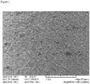
Figure 1 is a magnification of a wastegate spindle having surface indentations as are obtainable by shot peening the spindle with a substantially spherical shot media having a diameter of about 400 µm. The magnification is 100-fold. -
Figure 2 is a further magnification of a wastegate spindle shown inFig. 1 . The magnification is 250-fold. - In a first aspect, the present invention relates to a waste gate component for a turbo charger comprising an alloy of the following composition:
a) Ni 30 to 42 wt.-%, b) Cr 15 to 28 wt.-%, c) Co 1 to 5 wt.-%, d) Ti 1 to 4 wt.-%, e) optionally one or more elements selected from the group consisting of Mo, Al, Mn, W, Si and Nb, in particular one or more of elements in amounts as follows: Mo 0.5 to 4 wt.-%, Al 0.1 to 2 wt.-%, Mn 0.1 to 3 wt.-%, W 0.1 to 3 wt.-%, Si 0.5 to 4 wt.-%, and Nb 1 to 4 wt.-%,f) optionally other elements, in particular lanthanoids, boron and zirconium, in minor amounts which add up to a total amount of less than 2 wt.-%, g) Fe as balance, but at least in an amount of 20 wt.-%. - The alloy according to the first aspect of the invention comprises 30 to 42 wt.-% Ni. Advantageously, the alloy comprises 32 to 39 wt.-%, in particular 34 to 38 wt.-%, Ni. The alloy further comprises 15 to 28 wt.-% Cr. Advantageously, the alloy comprises 17 to 26 wt.-%, in particular 19 to 24 wt.-%, Cr. The alloy further comprises 1 to 5 wt.-% Co. Advantageously, the alloy comprises 1 to 5 wt.-%, in particular 1.5 to 4.5 wt.-%, Co. The alloy further comprises 1 to 5 wt.-% Ti. Advantageously, the alloy comprises 1.5 to 3.5 wt.-%, in particular 2.0 to 3.0 wt.-%, Ti. Alloys of this type were found to provide a balanced mix of mechanical, tribological, and corrosion-resistance properties required for the use as a waste gate component for a turbo charger. In addition, due to the high iron and low nickel content in comparison to Inconel 713C, the alloy is relatively inexpensive.
- The alloy may optionally contain one or more further elements to adjust its properties. In particular, the alloy may optionally comprise one or more elements selected from the group consisting of Mo, Al, Mn, W Si and Nb. Advantageously, the said elements may be used in the following amounts:
- Mo 0.5 to 4 wt.-%, in particular 1.0 to 3.0 wt.-%,
- Al 0.1 to 2 wt.-%, in particular 0.3 to 0.8 wt.-%,
- Mn 0.1 to 3 wt.-%, in particular 0.5 to 2.5 wt.-%,
- W 0.1 to 3 wt.-%, in particular 0.5 to 2.5 wt.-%,
- Si 0.5 to 4 wt.-%, in particular 0.6 to 2.4 wt.-%, and
-
Nb 1 to 4 wt.-%, in particular 1.7 to 2.5 wt.-%. - Besides Mo, Al, Mn, W, Si and Nb, the alloy may also contain other elements in minor amounts which add up to a total amount of less than 2 wt.-%. These other elements will typically be impurities introduced from raw materials or during the preparation of the alloy. However, other elements purposefully added in minor amounts to fine-tune alloy properties are also intended to be included in this definition as long as their total amount, together with the total amount of impurities, is less than 2 wt.-%. Examples of elements which may be added in minor amounts to fine-tune alloy properties include lanthanoids, boron or zirconium. These elements in combination with the impurities advantageously add up to a total amount of less than 1.5 wt.-%, more specifically less than 1 wt.-%, and in particular less than 0.5 wt.-%.
- The alloy may comprise Nb in an amount of 1 to 4 wt.-%, in particular 1.7 to 2.5 wt.-%, and/or W in an amount of 0.1 to 3 wt.-%, in particular 0.5 to 2.5 wt.-%, and/or Mo in an amount of 0.5 to 4 wt.-%, in particular 1.0 to 3.0 wt.-%, and C in an amount of less than 0.1 wt.-%, in particular in amounts of 0.02 to 0.09 wt.-%. Without wishing to be bound by theory, Nb, Mo, and W are thought to compete with Cr in the carbide formation. Besides providing their own potential benefits such as improving strength, wear and hot gas corrosion resistance to the alloy, the addition of Nb, Mo, and/or W is therefore believed to reduce chromium carbide formation. In combination with a relatively low amount of carbon in the alloy, the addition of Nb, Mo, and/or W may free up Cr on the alloy surface which then may form chromium oxides when exposed to hot exhaust gasses. Chromium oxide top coats may, in turn, reduce sliding abrasion and improve oxidation resistance.
- Advantageously, the alloy may contain Nb in an amount of 1 to 4 wt.-%, in particular 1.7 to 2.5 wt.-%, Mo in an amount of 0.5 to 4 wt.-%, in particular 1.0 to 3.0 wt.-%, W in an amount of 0.1 to 3 wt.-%, in particular 0.5 to 2.5 wt.-%, and C in an amount of less than 0.1 wt.-%, in particular in an amount of 0.02 to 0.09 wt.-%. In particular, the alloy may comprise Nb in an amount of 1.7 to 2.5 wt.-%, Mo in an amount of 1.0 to 3.0 wt.-%, W in an amount of 0.5 to 2.5 wt.-%, and C in an amount of 0.02 to 0.09 wt.-%.
- The alloy may also comprise between 0.5 and 10 wt.-% of one or more elements selected from Mn, Al, and Si. Advantageously, the alloy comprises Mn in an amount of 0.1 to 3 wt.-%, in particular 0.5 to 2.5 wt.-%, and/or Al in an amount of 0.1 to 2 wt.-%, in particular 0.3 to 0.8 wt.-%, and/or Si in an amount of 0.5 to 4 wt.-%, in particular 0.6 to 2.4 wt.-%, provided that the total amount of these elements add up to 0.5 and 10 wt.-%. In particular, the alloy may comprise Mn in an amount of 0.5 to 2.5 wt.-%, Al in an amount of 0.3 to 0.8 wt.-%, and Si in an amount of 0.6 to 2.4 wt.-%. Without wishing to be bound by theory, Mn, Al, and Si are thought to act as deoxidizing elements and may contribute to high temperature strength and toughness. In addition, Al and Si further increase resistance to scaling and, thus, may improve high temperature corrosion resistance and resistance to wear.
- The relatively high amount of chromium in the alloys of the invention already provides oxidation and corrosion resistance. The addition of Al and Si may be used to further adjust high temperature oxidation and corrosion resistance. In this context, the invention in particular also relates to a waste gate component for a turbo charger comprising an alloy of the following composition:
a) Ni 30 to 42 wt.-%, b) Cr 15 to 28 wt.-%, c) Co 1 to 5 wt.-%, d) Ti 1 to 4 wt.-%, e) optionally one or more elements selected from the group consisting of Mo, Mn, W, and Nb, in particular one or more of elements in amounts as follows: Mo 0.5 to 4 wt.-%, Mn 0.1 to 3 wt.-%, W 0.1 to 3 wt.-%, and Nb 1 to 4 wt.-%,f) A1 and/or Si in an amount of 0.5 to 10 wt.-%, g) optionally other elements, in particular lanthanoids, boron and zirconium, in minor amounts which add up to a total amount of less than 2 wt.-%, h) Fe as balance, but at least in an amount of 20 wt.-%, - The alloy may comprise 0.5 to 4 wt.-% Mo, 0.1 to 2 wt.-% Al, 0.1 to 3 wt.-% Mn, 0.1 to 3 wt.-% W, 0.5 to 4 wt.-% Si, 1 to 4 wt.-% Nb, and less than 0.1 wt.-% C. The alloy may also comprise 1.0 to 3.0 wt.-% Mo, 0.3 to 0.8 wt.-% Al, 0.5 to 2.5 wt.-% Mn, 0.5 to 2.5 wt.-% W, 0.6 to 2.4 wt.-% Si, 1.7 to 2.5 wt.-% Nb, and 0.02 to 0.09 wt.-% C.
- Advantageously, the alloy comprises 34 to 38 wt.-% Ni, 19 to 24 wt.-% Cr, 1.5 to 4.5 wt.-% Co, 2.0 to 3.0 wt.-% Ti, 1.0 to 3.0 wt.-% Mo, 0.3 to 0.8 wt.-% Al, 0.5 to 2.5 wt.-% Mn, 0.5 to 2.5 wt.-% W, 0.6 to 2.4 wt.-% Si, 1.7 to 2.5 wt.-% Nb, and 0.02 to 0.09 wt.-% C.
- From a purity standpoint, all of the above-described alloys advantageously contain less than 0.1 wt.-% C, less than 0.05 wt.-% P, less than 0.05 wt.-% S, and/or less than 0.04 wt.-% N.
- The alloy according to the invention may have good mechanical, chemical, and tribological properties, in particular at high temperatures. The alloy may be endowed with excellent Vickers hardness, ultimate tensile strength, elongation, ultimate elongation, yield strength, creep rate, salt water corrosions resistance, and oxidation stability. In particular, the waste gate components prepared from the alloy may have similar fatigue resistance as a like components prepared from Inconel 713C. The fatigue resistance may e.g. be tested by the fatigue resistance test in accordance with VB101 and/or VB102 of the Fraunhofer Institut für Betriebsfestigkeit und Systemzuverlassigkeit LBF, Darmstadt, Germany, at temperatures of about 950 °C.
- The alloy may further have an austenitic microstructure comprising second phase particles or aggregates of said second phase particles, wherein said particles have an average size of less than about 5 µm, in particular less than about 2 µm. In this context, the average size refers to the average size as measured/determined on the surface of the alloy or as measured/determined on a cutting plane substantially parallel to the surface of the alloy. The average grain size may e.g. be determined by using automatic image analysis according to e.g. ASTM E1245 (2008).
- The alloy for the waste gate component of the invention may be subjected to solution heat treatment, precipitation hardening, or both. In particular, the treatment described below was found to be useful for preparing the waste gate components of the invention:
In a second aspect, the present invention relates to a method for preparing a waste gate component for a turbo charger comprising an alloy of the following composition:a) Ni 30 to 42 wt.-%, b) Cr 15 to 28 wt.-%, c) Co 1 to 5 wt.-%, d) Ti 1 to 4 wt.-%, e) optionally one or more elements selected from the group consisting of Mo, Al, Mn, W, Si and Nb, in particular one or more of elements in amounts as follows: Mo 0.5 to 4 wt.-%, Al 0.1 to 2 wt.-%, Mn 0.1 to 3 wt.-%, W 0.1 to 3 wt.-%, Si 0.5 to 4 wt.-%, and Nb 1 to 4 wt.-%,f) optionally other elements, in particular lanthanoids, boron and zirconium, in minor amounts which add up to a total amount of less than 2 wt.-%, g) Fe as balance, but at least in an amount of 20 wt.-%; - i. tempering the alloy at 700 to 750°C, in particular 720 to 730 °C,
- ii. tempering the alloy at 600 to 640°C, in particular 615 to 625°C.
- The alloy to be treated according to the above method may be any alloy disclosed in the first aspect of the invention.
- The precipitation hardening according to the above method is advantageously performed for at least about 4 hours, in particular about 6 to about 12 hours, more specifically about 7 to about 9 hours, at about 700 to about 750°C, in particular about 720 to about 730 °C, followed by tempering the alloy for at least about 4 hours, in particular about 6 to about 12 hours, more specifically about 7 to about 9 hours, at about 600 to about 640°C, in particular about 615 to about 625°C. These indications of temperature and time may refer to the surface temperature of the tempered alloy workpiece or, in case of very large workpieces where there may exist a temperature gradient between the surface and the core during periods of temperature adjustment, optionally to the temperature of the core or any other location that takes longest to respond to the temperature adjustment.
- The solution heat treatment in the above method is performed at a temperature and for a duration that ensures a substantially homogeneous distribution of the alloying elements in the alloy. Suitable conditions may include heating the alloy to above about 950 °C for at least about 1 hour, in particular heating the alloy to about 980 to about 1050 °C for about 3 or more hours.
- Between the above-described steps of solution heat treatment and precipitation hardening, the alloy may further be subjected to recrystallization annealing. Recrystallization annealing may be performed for at least about 4 hours, in particular about 6 to about 12 hours, at a temperatures of about 830 to about 890 °C, in particular about 840 to about 880 °C.
- The alloy obtainable by the above described methods of the second aspect of the invention may be characterized by an austenitic microstructure comprising fine second phase particles and improved mechanical properties, in particular improved tensile strength. In particular, the above-described methods provide waste gate components comprising an alloy having the following composition:
a) Ni 30 to 42 wt.-%, b) Cr 15 to 28 wt.-%, c) Co 1 to 5 wt.-%, d) Ti 1 to 4 wt.-%, e) optionally one or more elements selected from the group consisting of Mo, Al, Mn, W, Si and Nb, in particular one or more of elements in amounts as follows: Mo 0.5 to 4 wt.-%, Al 0.1 to 2 wt.-%, Mn 0.1 to 3 wt.-%, W 0.1 to 3 wt.-%, Si 0.5 to 4 wt.-%, and Nb 1 to 4 wt.-%, f) optionally other elements, in particular lanthanoids, boron and zirconium, in minor amounts which add up to a total amount of less than 2 wt.-%, g) Fe as balance, but at least in an amount of 20 wt.-%, - In a third aspect, the present invention relates to a method of modifying the surface of a waste gate component for a turbo charger comprising an alloy of the following composition:
a) Ni 30 to 42 wt.-%, b) Cr 15 to 28 wt.-%, c) Co 1 to 5 wt.-%, d) Ti 1 to 4 wt.-%, e) optionally 0.5 to 4 wt.-% Mo, 0.1 to 2 wt.-% Al, 0.1 to 3 wt.-% Mn, 0.1 to 3 wt.-% W, 0.5 to 4 wt.-% Si, 1 to 4 wt.-% Nb, f) optionally other elements, in particular lanthanoids, boron and zirconium, in minor amounts which add up to a total amount of less than 2 wt.-%, g) Fe as balance, but at least in an amount of 20 wt.-%; - The alloy to be treated according to the above method may be any alloy disclosed in the first aspect of the invention.
- The method according to the third aspect of the invention modifies the surface of the waste gate component by producing a plurality of surface indentations on the surface of the waste gate component. Examples of such surface indentations are shown in
Fig.s 1 and2 . These surface indentations may have an average depth of about 20 to about 70 µm, in particular about 25 to about 55 µm. The average depth of the surface indentations may e.g. be determined by calculating the average depth on basis of about 100 neighbouring indentations. The depth of individual indentations may be determined by optical, spectroscopic or other means. The surface indentations may be characterized by a surface roughness, measured according to DIN EN ISO 4287 and/or 4288, as defined by an Rz-value of less than about 25 µm, in particular less than about 15µm, more specifically less than about 10 µm, or between about 2 and about 25 µm, more specifically between about 5 and about 15 about 15 µm. The Ra-value may be between about 1 and about 5 µm, in particular between about 2 and about 4 µm. - It was found that the plurality of surface indentations may improve the tribological performance of the waste gate component. Since the waste gate components of the turbocharger move or rotate in response to control inputs, an improvement in the tribological performance of its components also reduces the hysteresis of controlling the waste gate. Therefore, a waste gate component wherein at least part of the surface of a waste gate component is shot peened as described above may also have improved control quality. Advantageously, the shot peened waste gate component comprises in particular the spindle.
- In the context of improving the improvement in the tribological performance by shot peening, it may in particular be advantageous to use an alloy of the first aspect of the invention which comprises Nb in an amount of 1 to 4 wt.-%, in particular 1.7 to 2.5 wt.-%, and/or W in an amount of 0.1 to 3 wt.-%, in particular 0.5 to 2.5 wt.-%, and/or Mo in an amount of 0.5 to 4 wt.-%, in particular 1.0 to 3.0 wt.-%, and C in an amount of less than 0.1 wt.-%, in particular in amounts of 0.02 to 0.09 wt.-%. As explained above, it is believed that the addition of Nb, Mo, and/or W may free up Cr on the alloy surface which then may form chromium oxides which may, in turn, reduce sliding abrasion and improve oxidation resistance. Reducing sliding abrasion may further improve control quality. Improving oxidation resistance may help in maintaining the surface quality of the wastegate component for a longer period of time and, thus, may further improve long-term control quality.
- In the context of improving the tribological performance by shot peening, it may also be advantageous to use an alloy of the first aspect of the invention which comprises between 0.6 and 6 wt.-% of one or more elements selected from Al and Si. Advantageously, the alloy comprises Al in an amount of 0.1 to 2 wt.-%, in particular 0.3 to 0.8 wt.-%, and/or Si in an amount of 0.5 to 4 wt.-%, in particular 0.6 to 2.4 wt.-%. As explained above, it is believed that the addition of Si and/or Al may improve high temperature corrosion resistance and resistance to wear and, thus, may further improve short- and long-term control quality.
- The shot peening step according to the above method is advantageously performed with a substantially spherical shot material. Such substantially spherical shot media are commercially available, for instance as conditioned steel cut wire shot. Steel cut wire shot is prepared by cutting steel wire into cylindrical grains so that the respective length of the grain is substantially the same as the diameter of the wire. By rounding the cylinder edges a conditioned grain is created, classified in the grain shapes G1 (rounded edges), G2-(almost spherical grain) and G3 (spherical grain). A substantially spherical shot material is a G2 and G3-type material. Advantageously, the substantially spherical shot material is a G3 conditioned steel cut wire shot material. However, other shot materials may also be suitable, for instance substantially spherical mineralic shot media such as glass or ceramic pearl media. Advantageously, the substantially spherical shot material is selected form the group consisting of conditioned steel cut wire shot, glass pearls, ceramic pearls, copper shot, and brass shot. The substantially spherical shot material is in particular selected from conditioned steel cut wire shot, fineshot, glass pearls and ceramic pearls.
- The substantially spherical shot material is suitable to deform the surface of the waste gate component and may be harder than said surface. The Vickers hardness of the shot peening material may be from about 450 to about 850 HV, in particular from about 670 to about 730 HV. The average diameter of the substantially spherical shot material may be between about 100 µm and about 2000 µm, more specifically between about 200 and about 800 µm, in particular about 300 to about 600 µm.
- Advantageously, the substantially spherical shot material is a conditioned steel cut wire shot media having a Vickers hardness between about 670 to about 730 HV and an average diameter between about 200 and about 800 µm, in particular about 300 to about 600 µm.
- A waste gate component according to the invention may be shot peened as follows: The waste gate component such as a waste gate spindle is shot peened with an air blast system (e.g. a blast cabinet STD 1400 PS from Rösler Oberflachentechnik GmbH, Germany) using a conditioned steel cut wire shot media having a Vickers hardness between about 670 to about 730 HV and an average diameter between about 400 µm, using a blasting gun having one air nozzle of about 10 mm diameter and a pressure of about 2 bars. The distance between the workpiece and the nozzle is about 80 mm and the nozzle is angled at about 45°. The workpiece is rotated at about 48 rpm and the nozzle is moved 4 times over the workpiece at a speed of about 10 mm/sec.
- The shot-peened surface of the waste gate component may optionally be subj ected to one or more further shot peenings. A further shot peening may smoothen the edges of the indentation obtained by the first shot peening. The one or more further shoot peenings may be performed using the same, a harder or a softer peening material, the same or a smaller or a larger sized material, or any combination thereof. Advantageously, the waste gate component is subjected to at least one further shot peenings using a softer and/or smaller peening material than the 1st peening material. For instance, in case that the first shot peening material is a conditioned steel cut wire shot media having a Vickers hardness between about 670 to about 730 HV and an average diameter of between about 300 and about 800 µm, the second shot peening material may be glass pearls having a Moh hardness of about 5 or about 6, in particular about 6, and an average diameter of between about 20 and about 200 µm, or a fineshot media having a particle size of about 20 to 200 µm, in particular about 50 to about 150 µm.
- For instance, the second shot peening may be performed as follows: The waste gate component shot-peened as described above is shot peened for a second time with an air blast system (e.g. a blast cabinet STD 1400 PS from Rösler Oberflachentechnik GmbH, Germany) using glass perals having a Boh hardness of about 5 or about 6 and an average diameter of between about 150 µm and about 250 µm or fineshot having an average diameter of between about 50 and about 150 µm using a blasting gun having one air nozzle of about 10 mm diameter and a pressure of about 2 bars. The distance between the workpiece and the nozzle is about 80 mm and the nozzle is angled at about 45°. The workpiece is rotated at about 48 rpm and the nozzle is moved 4 times over the workpiece at a speed of about 10 mm/sec.
- The method according to the third aspect of the invention provides a waste gate component comprising an alloy having the following composition:
a) Ni 30 to 42 wt.-%, b) Cr 15 to 28 wt.-%, c) Co 1 to 5 wt.-%, d) Ti 1 to 4 wt.-%, e) optionally one or more elements selected from the group consisting of Mo, Al, Mn, W, Si and Nb, in particular one or more of elements in amounts as follows: Mo 0.5 to 4 wt.-%, Al 0.1 to 2 wt.-%, Mn 0.1 to 3 wt.-%, W 0.1 to 3 wt.-%, Si 0.5 to 4 wt.-%, and Nb 1 to 4 wt.-%,f) optionally other elements, in particular lanthanoids, boron and zirconium, in minor amounts which add up to a total amount of less than 2 wt.-%, g) Fe as balance, but at least in an amount of 20 wt.-%, - The above wastegate components may be further characterized as indicated for the waste gate components according to the first aspect of the invention. More specifically, it may be advantageous to combine the 1st, 2nd, and 3rd aspect of the invention to jointly improve the performance of the wastegate component. In particular, the invention relates to a waste gate component comprising an alloy having the following composition:
a) Ni 30 to 42 wt.-%, b) Cr 15 to 28 wt.-%, c) Co 1 to 5 wt.-%, d) Ti 1 to 4 wt.-%, e) optionally one or more elements selected from the group consisting of Mo, Al, Mn, W, Si and Nb, in particular one or more of elements in amounts as follows: Mo 0.5 to 4 wt.-%, Al 0.1 to 2 wt.-%, Mn 0.1 to 3 wt.-%, W 0.1 to 3 wt.-%, Si 0.5 to 4 wt.-%, and Nb 1 to 4 wt.-%, f) optionally other elements, in particular lanthanoids, boron and zirconium, in minor amounts which add up to a total amount of less than 2 wt.-%, g) Fe as balance, but at least in an amount of 20 wt.-%, - It may be further advantageous that the alloy of said wastegate component comprises Nb in an amount of 1 to 4 wt.-%, in particular 1.7 to 2.5 wt.-%, and/or W in an amount of 0.1 to 3 wt.-%, in particular 0.5 to 2.5 wt.-%, and/or Mo in an amount of 0.5 to 4 wt.-%, in particular 1.0 to 3.0 wt.-%, and C in an amount of less than 0.1 wt.-%, in particular in amounts of 0.02 to 0.09 wt.-%.
- It may be further advantageous that the alloy of said wastegate component comprises between 0.6 and 6 wt.-% of one or more elements selected from Al and Si. Advantageously, the alloy comprises Al in an amount of 0.1 to 2 wt.-%, in particular 0.3 to 0.8 wt.-%, and/or Si in an amount of 0.5 to 4 wt.-%, in particular 0.6 to 2.4 wt.-%.
- Finally, it may be further advantageous that the alloy of said wastegate component comprises Nb in an amount of 1 to 4 wt.-%, in particular 1.7 to 2.5 wt.-%, Mo in an amount of 0.5 to 4 wt.-%, in particular 1.0 to 3.0 wt.-%, W in an amount of 0.1 to 3 wt.-%, in particular 0.5 to 2.5 wt.-%, and C in an amount of less than 0.1 wt.-%, in particular in an amount of 0.02 to 0.09 wt.-%. In particular, the alloy may comprise Nb in an amount of 1.7 to 2.5 wt.-%, Mo in an amount of 1.0 to 3.0 wt.-%, W in an amount of 0.5 to 2.5 wt.-%, and C in an amount of 0.02 to 0.09 wt.-%.
- The above-discussed shot peening method of the third aspect is also applicable to other alloys. Thus, there is also generally provided, but not claimed, a method of modifying the surface of a waste gate component for a turbo charger wherein at least part of the surface of a waste gate component is shot peened with a substantially spherical shot material having an average diameter of between about 100 and about 2000 µm. The shot peening process may be further characterized as described for the third aspect of the invention.
- The alloys mentioned in this patent application can be prepared by routine methods well-known in metallurgy.
- Still further embodiments are within the scope of the following claims.
Claims (14)
- Waste gate component for a turbo charger comprising an alloy of the following composition:
a) Ni 30 to 42 wt.-%, b) Cr 15 to 28 wt.-%, c) Co 1 to 5 wt.-%, d) Ti 1 to 4 wt.-%, e) optionally one or more elements selected from the group consisting of Mo, Al, Mn, W, Si and Nb, in particular one or more of elements in amounts as follows: Mo 0.5 to 4 wt.-%, Al 0.1 to 2 wt.-%, Mn 0.1 to 3 wt.-%, W 0.1 to 3 wt.-%, Si 0.5 to 4 wt.-%, and Nb 1 to 4 wt.-%, f) optionally other elements, in particular lanthanoids, boron and zirconium, in minor amounts which add up to a total amount of less than 2 wt.-%, g) Fe as balance, but at least in an amount of 20 wt.-%. - Waste gate component according to claim 1, wherein the alloy comprises Nb in an amount of 1 to 4 wt.-% Nb, and/or W in an amount of 0.1 to 3 wt.-%, and/or Mo in an amount of 0.5 to 4 wt.-%, and C in the alloy is less than 0.1 wt.-%.
- Waste gate component according to claim 1, wherein the alloy comprises 0.5-4 wt.-% Mo, 0.1 to 2 wt.-% Al, and 0.1 to 3 wt.-% W.
- Waste gate component according to any one of claims 1 to 3, wherein the alloy comprises 0.5-4 wt.-% Mo, 0.1 to 2 wt.-% Al, 0.1 to 3 wt.-% Mn, 0.1 to 3 wt.-% W, 0.5 to 4 wt.-% Si, and 1 to 4 wt.-% Nb.
- Waste gate component according to any one of claims 1 to 4, wherein the alloy comprises
a) Ni 32 to 39 wt.-%, in particular 34 to 38 wt.-%, b) Cr 17 to 26 wt.-%, in particular 19 to 24 wt.-%, c) Co 1 to 5 wt.-%, in particular 1.5 to 4.5 wt.-%, d) Ti 1.5 to 3.5 wt.-%, in particular 2.0 to 3.0 wt.-% - Waste gate component according to any one of claims 1 to 5, wherein the alloy comprises 1.0 to 3.0 wt.-% Mo, 0.3 to 0.8 wt.-% Al, 0.5 to 2.5 wt.-% Mn, 0.5 to 2.5 wt.-% W, 0.6 to 2.4 wt.-% Si, and 1.7 to 2.5 wt.-% Nb.
- Waste gate component according to any one of claims 1 to 6, wherein the alloy comprises less than 0.05 wt.-% P, less than 0.05 wt.-% S, and less than 300 ppm, by weight, of N.
- Waste gate component according to any one of claims 1 to 7, wherein the alloy has been subjected to solution heat treatment, precipitation hardening, or both.
- Waste gate component according to any one of claims 1 to 8, wherein the alloy has an austenitic microstructure and comprises second phase particles or aggregates of said second phase particles, wherein said particles have an average grain size of less than 5 µm.
- Waste gate component according to any one of claims 1 to 9, wherein at least part of the surface of the component is preparable by shot peening the surface with a substantially spherical shot material having a diameter of between 100 and 2000 µm.
- Waste gate component according to any one of claims 1 to 10, wherein at least a part of the surface of the component has a plurality of indentations.
- Waste gate component according to any one of claims 1 to 11, wherein the component is a flap plate or a spindle.
- Method for preparing a waste gate component for a turbo charger comprising an alloy of the following composition:a) Ni 30 to 42 wt.-%,b) Cr 15 to 28 wt.-%,c) Co1 to 5 wt.-%,d) Ti 1 to 4 wt.-%,e) optionally 0.5-4 wt.-% Mo, 0.1 to 2 wt.-% Al, 0.1 to 3 wt.-% Mn, 0.1 to 3 wt.-% W, 0.5 to 4 wt.-% Si, 1 to 4 wt.-% Nb,f) optionally other elements, in particular lanthanoids, boron and zirconium, in minor amounts which add up to a total amount of less than 2 wt.-%,g) Fe as balance, but at least in an amount of 20 wt.-%;wherein the alloy is subjected to solution heat treatment, followed by precipitation hardening, and wherein the precipitation hardening includes the following steps, in that order:i. tempering the alloy at 700 to 750°C, in particular 720 to 730 °Cii. tempering the alloy at 600 to 640°C, in particular 615 to 625°C.
- Method of modifying the surface of a waste gate component for a turbo charger comprising an alloy of the following composition:
a) Ni 30 to 42 wt.-%, b) Cr 15 to 28 wt.-%, c) Co 1 to 5 wt.-%, d) Ti 1 to 4 wt.-%, e) optionally 0.5-4 wt.-% Mo, 0.1 to 2 wt.-% Al, 0.1 to 3 wt.-% Mn, 0.1 to 3 wt.-% W, 0.5 to 4 wt.-% Si, 1 to 4 wt.-% Nb, f) optionally other elements, in particular lanthanoids, boron and zirconium, in minor amounts which add up to a total amount of less than 2 wt.-% , g) Fe as balance, but at least in an amount of 20 wt.-%;
Applications Claiming Priority (2)
| Application Number | Priority Date | Filing Date | Title |
|---|---|---|---|
| EP15201335 | 2015-12-18 | ||
| PCT/US2016/065254 WO2017105942A1 (en) | 2015-12-18 | 2016-12-07 | Wastegate component comprising a novel alloy |
Publications (2)
| Publication Number | Publication Date |
|---|---|
| EP3390677A1 EP3390677A1 (en) | 2018-10-24 |
| EP3390677B1 true EP3390677B1 (en) | 2023-01-25 |
Family
ID=55068793
Family Applications (1)
| Application Number | Title | Priority Date | Filing Date |
|---|---|---|---|
| EP16810595.5A Active EP3390677B1 (en) | 2015-12-18 | 2016-12-07 | Wastegate component comprising a novel alloy |
Country Status (6)
| Country | Link |
|---|---|
| US (1) | US11306376B2 (en) |
| EP (1) | EP3390677B1 (en) |
| JP (1) | JP7114464B2 (en) |
| KR (1) | KR20180095557A (en) |
| CN (1) | CN108431258B (en) |
| WO (1) | WO2017105942A1 (en) |
Families Citing this family (1)
| Publication number | Priority date | Publication date | Assignee | Title |
|---|---|---|---|---|
| BR102018068426A2 (en) * | 2018-09-12 | 2020-03-24 | Mahle Metal Leve S.A. | RELIEF VALVE FOR A TURBOCOMPRESSOR AND PROCESS FOR RELIEF VALVE MANUFACTURING |
Family Cites Families (27)
| Publication number | Priority date | Publication date | Assignee | Title |
|---|---|---|---|---|
| JPS51110414A (en) * | 1975-03-25 | 1976-09-30 | Tokushu Seiko Co Ltd | REIKANATSUZONYOTSUTE SEIZONOKANONA JIDOSHAYOKOSEINOHAIKIBARUBUKO |
| US4705463A (en) | 1983-04-21 | 1987-11-10 | The Garrett Corporation | Compressor wheel assembly for turbochargers |
| US5409415A (en) * | 1992-07-02 | 1995-04-25 | Nikkato Corp. | Shot method |
| US5295785A (en) | 1992-12-23 | 1994-03-22 | Caterpillar Inc. | Turbocharger having reduced noise emissions |
| US5660938A (en) | 1993-08-19 | 1997-08-26 | Hitachi Metals, Ltd., | Fe-Ni-Cr-base superalloy, engine valve and knitted mesh supporter for exhaust gas catalyzer |
| JP2963842B2 (en) * | 1994-06-15 | 1999-10-18 | 大同特殊鋼株式会社 | Alloy for exhaust valve |
| JPH09279309A (en) * | 1996-04-12 | 1997-10-28 | Daido Steel Co Ltd | Fe-Cr-Ni heat resistant alloy |
| DK173348B1 (en) * | 1996-06-07 | 2000-08-07 | Man B & W Diesel As | Exhaust valve for an internal combustion engine |
| JPH10298682A (en) * | 1997-04-25 | 1998-11-10 | Toshiba Corp | Heat-resistant alloy, method of manufacturing heat-resistant alloy, and heat-resistant alloy part |
| JPH11117019A (en) * | 1997-10-09 | 1999-04-27 | Daido Steel Co Ltd | Manufacturing method of heat resistant parts |
| US5945067A (en) * | 1998-10-23 | 1999-08-31 | Inco Alloys International, Inc. | High strength corrosion resistant alloy |
| CN1281851C (en) * | 2003-06-02 | 2006-10-25 | 北京特冶工贸有限责任公司 | Double-metal exhaust gate for diesel engine of diesel locomotive and its manufacture |
| JP4830466B2 (en) * | 2005-01-19 | 2011-12-07 | 大同特殊鋼株式会社 | Heat-resistant alloy for exhaust valves that can withstand use at 900 ° C and exhaust valves using the alloys |
| DE102007025758A1 (en) * | 2007-06-01 | 2008-12-04 | Mahle International Gmbh | seal |
| US20090081074A1 (en) | 2007-06-07 | 2009-03-26 | Celso Antonio Barbosa | Wear resistant alloy for high temprature applications |
| CA2688507C (en) * | 2009-12-16 | 2014-09-16 | Villares Metals S/A | Alloys with high corrosion resistance for engine valve applications |
| CN103827463B (en) | 2011-10-20 | 2018-05-11 | 博格华纳公司 | Turbocharger and parts for the turbocharger |
| JP2013185552A (en) * | 2012-03-09 | 2013-09-19 | Ihi Corp | Variable flow valve mechanism and vehicle supercharger |
| JP5888737B2 (en) * | 2012-05-21 | 2016-03-22 | 日本冶金工業株式会社 | Austenitic Fe-Ni-Cr alloy |
| JP2014080651A (en) * | 2012-10-16 | 2014-05-08 | National Institute For Materials Science | Nickel-iron-based alloy |
| JP5998950B2 (en) | 2013-01-24 | 2016-09-28 | 新日鐵住金株式会社 | Austenitic heat-resistant alloy members |
| JP6315319B2 (en) * | 2013-04-19 | 2018-04-25 | 日立金属株式会社 | Method for producing Fe-Ni base superalloy |
| DE102013214464A1 (en) * | 2013-07-24 | 2015-01-29 | Johannes Eyl | Method for producing a chromium-containing alloy and chromium-containing alloy |
| CN103695806B (en) * | 2013-12-10 | 2016-08-17 | 江苏武进不锈股份有限公司 | A kind of austenitic heat-resistance steel |
| DE102014001328B4 (en) | 2014-02-04 | 2016-04-21 | VDM Metals GmbH | Curing nickel-chromium-iron-titanium-aluminum alloy with good wear resistance, creep resistance, corrosion resistance and processability |
| DE102014001330B4 (en) * | 2014-02-04 | 2016-05-12 | VDM Metals GmbH | Curing nickel-chromium-cobalt-titanium-aluminum alloy with good wear resistance, creep resistance, corrosion resistance and processability |
| CN104195474B (en) * | 2014-07-30 | 2017-02-15 | 保定风帆精密铸造制品有限公司 | High-temperature-resistant alloy casting and preparation method thereof |
-
2016
- 2016-12-07 CN CN201680074546.9A patent/CN108431258B/en not_active Expired - Fee Related
- 2016-12-07 KR KR1020187018563A patent/KR20180095557A/en not_active Withdrawn
- 2016-12-07 JP JP2018531235A patent/JP7114464B2/en active Active
- 2016-12-07 US US16/063,369 patent/US11306376B2/en active Active
- 2016-12-07 EP EP16810595.5A patent/EP3390677B1/en active Active
- 2016-12-07 WO PCT/US2016/065254 patent/WO2017105942A1/en not_active Ceased
Also Published As
| Publication number | Publication date |
|---|---|
| EP3390677A1 (en) | 2018-10-24 |
| KR20180095557A (en) | 2018-08-27 |
| JP2019505662A (en) | 2019-02-28 |
| CN108431258A (en) | 2018-08-21 |
| CN108431258B (en) | 2021-11-09 |
| US20190003020A1 (en) | 2019-01-03 |
| WO2017105942A1 (en) | 2017-06-22 |
| JP7114464B2 (en) | 2022-08-08 |
| US11306376B2 (en) | 2022-04-19 |
Similar Documents
| Publication | Publication Date | Title |
|---|---|---|
| CN114672738B (en) | High performance iron-based alloys for engine valve train applications, methods of making and uses thereof | |
| CN105579594B (en) | Iron-based alloys, methods for their preparation and uses thereof | |
| CN107075629B (en) | Austenitic stainless steel plate | |
| DE112009002014B4 (en) | Turbocharger and vane for this | |
| JP7050520B2 (en) | Manufacturing method of austenitic stainless steel sheet for exhaust parts and austenitic stainless steel sheet for exhaust parts and exhaust parts | |
| EP3138934B1 (en) | Martensitic stainless si-deoxidized cold rolled and annealed steel sheet and metal gasket | |
| JP2017508884A (en) | Hardening nickel / chromium / cobalt / titanium / aluminum alloys with good wear resistance, creep resistance, corrosion resistance, and workability | |
| KR20150053827A (en) | Ni-Cr-Co-BASED ALLOY HAVING HIGH-TEMPERATURE CORROSION RESISTANCE PROPERTIES, AND POPPET VALVE HAVING SURFACE MODIFIED WITH SAME | |
| EP1837411A1 (en) | Ni-based super alloy | |
| KR102062031B1 (en) | Engine exhaust valve for large ship and method for manufacturing the same | |
| JP6485692B2 (en) | Heat resistant alloy with excellent high temperature strength, method for producing the same and heat resistant alloy spring | |
| US11306376B2 (en) | Wastegate component comprising a novel alloy | |
| TW201617462A (en) | Method for manufacturing austenitic alloy steel | |
| CN109252088A (en) | Ferritic stainless steel and heat-resistant part | |
| EP3048178A1 (en) | Engine exhaust valve for large ship and method for manufacturing the same | |
| JPH10298682A (en) | Heat-resistant alloy, method of manufacturing heat-resistant alloy, and heat-resistant alloy part | |
| US20070137050A1 (en) | Razor blades and compositions and processes for the production of razor blades | |
| JP2014189822A (en) | Steel for anticorrosive plastic molding die excellent in specularity | |
| JP7134052B2 (en) | MARTENSITE STAINLESS STEEL MATERIAL AND MANUFACTURING METHOD THEREOF AND SLIDING MEMBER | |
| CN102517519B (en) | Air valve steel for internal combustion engine | |
| CN120485599B (en) | Corrosion-resistant nickel-based superalloy, preparation method and application thereof | |
| US11685972B2 (en) | Ni-based alloy and valve | |
| CN110318009A (en) | The solenoid valve alloy material of easy cold-heading | |
| CN119320920A (en) | Method for improving high-temperature durability of deformed nickel-iron-chromium-based superalloy tube | |
| CN120696254A (en) | A slender valve alloy bar and its anti-deformation method |
Legal Events
| Date | Code | Title | Description |
|---|---|---|---|
| STAA | Information on the status of an ep patent application or granted ep patent |
Free format text: STATUS: UNKNOWN |
|
| STAA | Information on the status of an ep patent application or granted ep patent |
Free format text: STATUS: THE INTERNATIONAL PUBLICATION HAS BEEN MADE |
|
| PUAI | Public reference made under article 153(3) epc to a published international application that has entered the european phase |
Free format text: ORIGINAL CODE: 0009012 |
|
| STAA | Information on the status of an ep patent application or granted ep patent |
Free format text: STATUS: REQUEST FOR EXAMINATION WAS MADE |
|
| 17P | Request for examination filed |
Effective date: 20180717 |
|
| AK | Designated contracting states |
Kind code of ref document: A1 Designated state(s): AL AT BE BG CH CY CZ DE DK EE ES FI FR GB GR HR HU IE IS IT LI LT LU LV MC MK MT NL NO PL PT RO RS SE SI SK SM TR |
|
| AX | Request for extension of the european patent |
Extension state: BA ME |
|
| DAV | Request for validation of the european patent (deleted) | ||
| DAX | Request for extension of the european patent (deleted) | ||
| STAA | Information on the status of an ep patent application or granted ep patent |
Free format text: STATUS: EXAMINATION IS IN PROGRESS |
|
| 17Q | First examination report despatched |
Effective date: 20200827 |
|
| GRAP | Despatch of communication of intention to grant a patent |
Free format text: ORIGINAL CODE: EPIDOSNIGR1 |
|
| STAA | Information on the status of an ep patent application or granted ep patent |
Free format text: STATUS: GRANT OF PATENT IS INTENDED |
|
| INTG | Intention to grant announced |
Effective date: 20220823 |
|
| GRAS | Grant fee paid |
Free format text: ORIGINAL CODE: EPIDOSNIGR3 |
|
| GRAA | (expected) grant |
Free format text: ORIGINAL CODE: 0009210 |
|
| STAA | Information on the status of an ep patent application or granted ep patent |
Free format text: STATUS: THE PATENT HAS BEEN GRANTED |
|
| AK | Designated contracting states |
Kind code of ref document: B1 Designated state(s): AL AT BE BG CH CY CZ DE DK EE ES FI FR GB GR HR HU IE IS IT LI LT LU LV MC MK MT NL NO PL PT RO RS SE SI SK SM TR |
|
| REG | Reference to a national code |
Ref country code: GB Ref legal event code: FG4D |
|
| REG | Reference to a national code |
Ref country code: CH Ref legal event code: EP |
|
| REG | Reference to a national code |
Ref country code: AT Ref legal event code: REF Ref document number: 1545953 Country of ref document: AT Kind code of ref document: T Effective date: 20230215 Ref country code: IE Ref legal event code: FG4D |
|
| REG | Reference to a national code |
Ref country code: DE Ref legal event code: R096 Ref document number: 602016077631 Country of ref document: DE |
|
| REG | Reference to a national code |
Ref country code: LT Ref legal event code: MG9D |
|
| REG | Reference to a national code |
Ref country code: NL Ref legal event code: MP Effective date: 20230125 |
|
| P01 | Opt-out of the competence of the unified patent court (upc) registered |
Effective date: 20230327 |
|
| REG | Reference to a national code |
Ref country code: AT Ref legal event code: MK05 Ref document number: 1545953 Country of ref document: AT Kind code of ref document: T Effective date: 20230125 |
|
| PG25 | Lapsed in a contracting state [announced via postgrant information from national office to epo] |
Ref country code: NL Free format text: LAPSE BECAUSE OF FAILURE TO SUBMIT A TRANSLATION OF THE DESCRIPTION OR TO PAY THE FEE WITHIN THE PRESCRIBED TIME-LIMIT Effective date: 20230125 |
|
| PG25 | Lapsed in a contracting state [announced via postgrant information from national office to epo] |
Ref country code: RS Free format text: LAPSE BECAUSE OF FAILURE TO SUBMIT A TRANSLATION OF THE DESCRIPTION OR TO PAY THE FEE WITHIN THE PRESCRIBED TIME-LIMIT Effective date: 20230125 Ref country code: PT Free format text: LAPSE BECAUSE OF FAILURE TO SUBMIT A TRANSLATION OF THE DESCRIPTION OR TO PAY THE FEE WITHIN THE PRESCRIBED TIME-LIMIT Effective date: 20230525 Ref country code: NO Free format text: LAPSE BECAUSE OF FAILURE TO SUBMIT A TRANSLATION OF THE DESCRIPTION OR TO PAY THE FEE WITHIN THE PRESCRIBED TIME-LIMIT Effective date: 20230425 Ref country code: LV Free format text: LAPSE BECAUSE OF FAILURE TO SUBMIT A TRANSLATION OF THE DESCRIPTION OR TO PAY THE FEE WITHIN THE PRESCRIBED TIME-LIMIT Effective date: 20230125 Ref country code: LT Free format text: LAPSE BECAUSE OF FAILURE TO SUBMIT A TRANSLATION OF THE DESCRIPTION OR TO PAY THE FEE WITHIN THE PRESCRIBED TIME-LIMIT Effective date: 20230125 Ref country code: HR Free format text: LAPSE BECAUSE OF FAILURE TO SUBMIT A TRANSLATION OF THE DESCRIPTION OR TO PAY THE FEE WITHIN THE PRESCRIBED TIME-LIMIT Effective date: 20230125 Ref country code: ES Free format text: LAPSE BECAUSE OF FAILURE TO SUBMIT A TRANSLATION OF THE DESCRIPTION OR TO PAY THE FEE WITHIN THE PRESCRIBED TIME-LIMIT Effective date: 20230125 Ref country code: AT Free format text: LAPSE BECAUSE OF FAILURE TO SUBMIT A TRANSLATION OF THE DESCRIPTION OR TO PAY THE FEE WITHIN THE PRESCRIBED TIME-LIMIT Effective date: 20230125 |
|
| PG25 | Lapsed in a contracting state [announced via postgrant information from national office to epo] |
Ref country code: SE Free format text: LAPSE BECAUSE OF FAILURE TO SUBMIT A TRANSLATION OF THE DESCRIPTION OR TO PAY THE FEE WITHIN THE PRESCRIBED TIME-LIMIT Effective date: 20230125 Ref country code: PL Free format text: LAPSE BECAUSE OF FAILURE TO SUBMIT A TRANSLATION OF THE DESCRIPTION OR TO PAY THE FEE WITHIN THE PRESCRIBED TIME-LIMIT Effective date: 20230125 Ref country code: IS Free format text: LAPSE BECAUSE OF FAILURE TO SUBMIT A TRANSLATION OF THE DESCRIPTION OR TO PAY THE FEE WITHIN THE PRESCRIBED TIME-LIMIT Effective date: 20230525 Ref country code: GR Free format text: LAPSE BECAUSE OF FAILURE TO SUBMIT A TRANSLATION OF THE DESCRIPTION OR TO PAY THE FEE WITHIN THE PRESCRIBED TIME-LIMIT Effective date: 20230426 Ref country code: FI Free format text: LAPSE BECAUSE OF FAILURE TO SUBMIT A TRANSLATION OF THE DESCRIPTION OR TO PAY THE FEE WITHIN THE PRESCRIBED TIME-LIMIT Effective date: 20230125 |
|
| REG | Reference to a national code |
Ref country code: DE Ref legal event code: R097 Ref document number: 602016077631 Country of ref document: DE |
|
| PG25 | Lapsed in a contracting state [announced via postgrant information from national office to epo] |
Ref country code: SM Free format text: LAPSE BECAUSE OF FAILURE TO SUBMIT A TRANSLATION OF THE DESCRIPTION OR TO PAY THE FEE WITHIN THE PRESCRIBED TIME-LIMIT Effective date: 20230125 Ref country code: RO Free format text: LAPSE BECAUSE OF FAILURE TO SUBMIT A TRANSLATION OF THE DESCRIPTION OR TO PAY THE FEE WITHIN THE PRESCRIBED TIME-LIMIT Effective date: 20230125 Ref country code: EE Free format text: LAPSE BECAUSE OF FAILURE TO SUBMIT A TRANSLATION OF THE DESCRIPTION OR TO PAY THE FEE WITHIN THE PRESCRIBED TIME-LIMIT Effective date: 20230125 Ref country code: DK Free format text: LAPSE BECAUSE OF FAILURE TO SUBMIT A TRANSLATION OF THE DESCRIPTION OR TO PAY THE FEE WITHIN THE PRESCRIBED TIME-LIMIT Effective date: 20230125 Ref country code: CZ Free format text: LAPSE BECAUSE OF FAILURE TO SUBMIT A TRANSLATION OF THE DESCRIPTION OR TO PAY THE FEE WITHIN THE PRESCRIBED TIME-LIMIT Effective date: 20230125 |
|
| PG25 | Lapsed in a contracting state [announced via postgrant information from national office to epo] |
Ref country code: SK Free format text: LAPSE BECAUSE OF FAILURE TO SUBMIT A TRANSLATION OF THE DESCRIPTION OR TO PAY THE FEE WITHIN THE PRESCRIBED TIME-LIMIT Effective date: 20230125 |
|
| PLBE | No opposition filed within time limit |
Free format text: ORIGINAL CODE: 0009261 |
|
| STAA | Information on the status of an ep patent application or granted ep patent |
Free format text: STATUS: NO OPPOSITION FILED WITHIN TIME LIMIT |
|
| 26N | No opposition filed |
Effective date: 20231026 |
|
| PG25 | Lapsed in a contracting state [announced via postgrant information from national office to epo] |
Ref country code: SI Free format text: LAPSE BECAUSE OF FAILURE TO SUBMIT A TRANSLATION OF THE DESCRIPTION OR TO PAY THE FEE WITHIN THE PRESCRIBED TIME-LIMIT Effective date: 20230125 |
|
| PG25 | Lapsed in a contracting state [announced via postgrant information from national office to epo] |
Ref country code: IT Free format text: LAPSE BECAUSE OF FAILURE TO SUBMIT A TRANSLATION OF THE DESCRIPTION OR TO PAY THE FEE WITHIN THE PRESCRIBED TIME-LIMIT Effective date: 20230125 |
|
| REG | Reference to a national code |
Ref country code: CH Ref legal event code: PL |
|
| PG25 | Lapsed in a contracting state [announced via postgrant information from national office to epo] |
Ref country code: LU Free format text: LAPSE BECAUSE OF NON-PAYMENT OF DUE FEES Effective date: 20231207 |
|
| PG25 | Lapsed in a contracting state [announced via postgrant information from national office to epo] |
Ref country code: MC Free format text: LAPSE BECAUSE OF FAILURE TO SUBMIT A TRANSLATION OF THE DESCRIPTION OR TO PAY THE FEE WITHIN THE PRESCRIBED TIME-LIMIT Effective date: 20230125 |
|
| GBPC | Gb: european patent ceased through non-payment of renewal fee |
Effective date: 20231207 |
|
| REG | Reference to a national code |
Ref country code: BE Ref legal event code: MM Effective date: 20231231 |
|
| PG25 | Lapsed in a contracting state [announced via postgrant information from national office to epo] |
Ref country code: MC Free format text: LAPSE BECAUSE OF FAILURE TO SUBMIT A TRANSLATION OF THE DESCRIPTION OR TO PAY THE FEE WITHIN THE PRESCRIBED TIME-LIMIT Effective date: 20230125 Ref country code: LU Free format text: LAPSE BECAUSE OF NON-PAYMENT OF DUE FEES Effective date: 20231207 |
|
| REG | Reference to a national code |
Ref country code: IE Ref legal event code: MM4A |
|
| PG25 | Lapsed in a contracting state [announced via postgrant information from national office to epo] |
Ref country code: IE Free format text: LAPSE BECAUSE OF NON-PAYMENT OF DUE FEES Effective date: 20231207 |
|
| PG25 | Lapsed in a contracting state [announced via postgrant information from national office to epo] |
Ref country code: GB Free format text: LAPSE BECAUSE OF NON-PAYMENT OF DUE FEES Effective date: 20231207 |
|
| PG25 | Lapsed in a contracting state [announced via postgrant information from national office to epo] |
Ref country code: BE Free format text: LAPSE BECAUSE OF NON-PAYMENT OF DUE FEES Effective date: 20231231 |
|
| PG25 | Lapsed in a contracting state [announced via postgrant information from national office to epo] |
Ref country code: FR Free format text: LAPSE BECAUSE OF NON-PAYMENT OF DUE FEES Effective date: 20231231 |
|
| PG25 | Lapsed in a contracting state [announced via postgrant information from national office to epo] |
Ref country code: CH Free format text: LAPSE BECAUSE OF NON-PAYMENT OF DUE FEES Effective date: 20231231 |
|
| PG25 | Lapsed in a contracting state [announced via postgrant information from national office to epo] |
Ref country code: IE Free format text: LAPSE BECAUSE OF NON-PAYMENT OF DUE FEES Effective date: 20231207 Ref country code: GB Free format text: LAPSE BECAUSE OF NON-PAYMENT OF DUE FEES Effective date: 20231207 Ref country code: FR Free format text: LAPSE BECAUSE OF NON-PAYMENT OF DUE FEES Effective date: 20231231 Ref country code: CH Free format text: LAPSE BECAUSE OF NON-PAYMENT OF DUE FEES Effective date: 20231231 Ref country code: BE Free format text: LAPSE BECAUSE OF NON-PAYMENT OF DUE FEES Effective date: 20231231 |
|
| PG25 | Lapsed in a contracting state [announced via postgrant information from national office to epo] |
Ref country code: BG Free format text: LAPSE BECAUSE OF FAILURE TO SUBMIT A TRANSLATION OF THE DESCRIPTION OR TO PAY THE FEE WITHIN THE PRESCRIBED TIME-LIMIT Effective date: 20230125 |
|
| PG25 | Lapsed in a contracting state [announced via postgrant information from national office to epo] |
Ref country code: BG Free format text: LAPSE BECAUSE OF FAILURE TO SUBMIT A TRANSLATION OF THE DESCRIPTION OR TO PAY THE FEE WITHIN THE PRESCRIBED TIME-LIMIT Effective date: 20230125 |
|
| PGFP | Annual fee paid to national office [announced via postgrant information from national office to epo] |
Ref country code: DE Payment date: 20241111 Year of fee payment: 9 |
|
| PG25 | Lapsed in a contracting state [announced via postgrant information from national office to epo] |
Ref country code: CY Free format text: LAPSE BECAUSE OF FAILURE TO SUBMIT A TRANSLATION OF THE DESCRIPTION OR TO PAY THE FEE WITHIN THE PRESCRIBED TIME-LIMIT; INVALID AB INITIO Effective date: 20161207 |
|
| PG25 | Lapsed in a contracting state [announced via postgrant information from national office to epo] |
Ref country code: HU Free format text: LAPSE BECAUSE OF FAILURE TO SUBMIT A TRANSLATION OF THE DESCRIPTION OR TO PAY THE FEE WITHIN THE PRESCRIBED TIME-LIMIT; INVALID AB INITIO Effective date: 20161207 |
|
| PG25 | Lapsed in a contracting state [announced via postgrant information from national office to epo] |
Ref country code: TR Free format text: LAPSE BECAUSE OF FAILURE TO SUBMIT A TRANSLATION OF THE DESCRIPTION OR TO PAY THE FEE WITHIN THE PRESCRIBED TIME-LIMIT Effective date: 20230125 |