EP3390042B1 - Method for the autoclave-free lamination of a laminated glazing - Google Patents
Method for the autoclave-free lamination of a laminated glazing Download PDFInfo
- Publication number
- EP3390042B1 EP3390042B1 EP16806203.2A EP16806203A EP3390042B1 EP 3390042 B1 EP3390042 B1 EP 3390042B1 EP 16806203 A EP16806203 A EP 16806203A EP 3390042 B1 EP3390042 B1 EP 3390042B1
- Authority
- EP
- European Patent Office
- Prior art keywords
- stack sequence
- calender
- sequence
- stack
- vacuum
- Prior art date
- Legal status (The legal status is an assumption and is not a legal conclusion. Google has not performed a legal analysis and makes no representation as to the accuracy of the status listed.)
- Active
Links
- 238000000034 method Methods 0.000 title claims description 91
- 238000003475 lamination Methods 0.000 title claims description 15
- 238000010438 heat treatment Methods 0.000 claims description 34
- 239000000758 substrate Substances 0.000 claims description 33
- 239000002131 composite material Substances 0.000 claims description 19
- 238000000576 coating method Methods 0.000 claims description 18
- 229920002037 poly(vinyl butyral) polymer Polymers 0.000 claims description 18
- 239000011248 coating agent Substances 0.000 claims description 17
- 229920001971 elastomer Polymers 0.000 claims description 16
- 239000000806 elastomer Substances 0.000 claims description 16
- 238000001816 cooling Methods 0.000 claims description 10
- -1 polyethylene Polymers 0.000 claims description 8
- XLYOFNOQVPJJNP-UHFFFAOYSA-N water Substances O XLYOFNOQVPJJNP-UHFFFAOYSA-N 0.000 claims description 8
- 238000003825 pressing Methods 0.000 claims description 6
- 239000004698 Polyethylene Substances 0.000 claims description 4
- 239000004743 Polypropylene Substances 0.000 claims description 4
- VYPSYNLAJGMNEJ-UHFFFAOYSA-N Silicium dioxide Chemical compound O=[Si]=O VYPSYNLAJGMNEJ-UHFFFAOYSA-N 0.000 claims description 4
- 229910052782 aluminium Inorganic materials 0.000 claims description 4
- XAGFODPZIPBFFR-UHFFFAOYSA-N aluminium Chemical compound [Al] XAGFODPZIPBFFR-UHFFFAOYSA-N 0.000 claims description 4
- 239000011521 glass Substances 0.000 claims description 4
- 229920000573 polyethylene Polymers 0.000 claims description 4
- 229920001155 polypropylene Polymers 0.000 claims description 4
- 239000007787 solid Substances 0.000 claims description 4
- 238000004519 manufacturing process Methods 0.000 claims description 3
- 239000000203 mixture Substances 0.000 claims description 3
- 229920003229 poly(methyl methacrylate) Polymers 0.000 claims description 3
- 239000004417 polycarbonate Substances 0.000 claims description 3
- 229920000515 polycarbonate Polymers 0.000 claims description 3
- 239000004926 polymethyl methacrylate Substances 0.000 claims description 3
- 239000005361 soda-lime glass Substances 0.000 claims description 3
- 239000005388 borosilicate glass Substances 0.000 claims description 2
- 239000005357 flat glass Substances 0.000 claims description 2
- 239000005329 float glass Substances 0.000 claims description 2
- 229910052751 metal Inorganic materials 0.000 claims description 2
- 239000002184 metal Substances 0.000 claims description 2
- 229910001220 stainless steel Inorganic materials 0.000 claims description 2
- 239000010935 stainless steel Substances 0.000 claims description 2
- 229920000642 polymer Polymers 0.000 claims 1
- 230000032258 transport Effects 0.000 description 25
- 230000008569 process Effects 0.000 description 21
- 238000005452 bending Methods 0.000 description 4
- 230000005540 biological transmission Effects 0.000 description 4
- 229920003023 plastic Polymers 0.000 description 4
- 239000004033 plastic Substances 0.000 description 4
- 238000013022 venting Methods 0.000 description 4
- 230000008901 benefit Effects 0.000 description 3
- 229920001169 thermoplastic Polymers 0.000 description 3
- 239000004416 thermosoftening plastic Substances 0.000 description 3
- BLRPTPMANUNPDV-UHFFFAOYSA-N Silane Chemical compound [SiH4] BLRPTPMANUNPDV-UHFFFAOYSA-N 0.000 description 2
- 238000010586 diagram Methods 0.000 description 2
- 229920000139 polyethylene terephthalate Polymers 0.000 description 2
- 239000005020 polyethylene terephthalate Substances 0.000 description 2
- 239000004800 polyvinyl chloride Substances 0.000 description 2
- 229920000915 polyvinyl chloride Polymers 0.000 description 2
- 239000010453 quartz Substances 0.000 description 2
- 229920005989 resin Polymers 0.000 description 2
- 239000011347 resin Substances 0.000 description 2
- 229910000077 silane Inorganic materials 0.000 description 2
- 239000004812 Fluorinated ethylene propylene Substances 0.000 description 1
- 241001115479 Opheodrys Species 0.000 description 1
- 239000004952 Polyamide Substances 0.000 description 1
- 239000004793 Polystyrene Substances 0.000 description 1
- 239000004372 Polyvinyl alcohol Substances 0.000 description 1
- XUIMIQQOPSSXEZ-UHFFFAOYSA-N Silicon Chemical compound [Si] XUIMIQQOPSSXEZ-UHFFFAOYSA-N 0.000 description 1
- 150000001252 acrylic acid derivatives Chemical class 0.000 description 1
- 230000009471 action Effects 0.000 description 1
- 239000002318 adhesion promoter Substances 0.000 description 1
- 230000015572 biosynthetic process Effects 0.000 description 1
- 238000005266 casting Methods 0.000 description 1
- 230000006835 compression Effects 0.000 description 1
- 238000007906 compression Methods 0.000 description 1
- 238000010276 construction Methods 0.000 description 1
- 229920001577 copolymer Polymers 0.000 description 1
- 230000001419 dependent effect Effects 0.000 description 1
- 230000000694 effects Effects 0.000 description 1
- 238000005516 engineering process Methods 0.000 description 1
- 229920000840 ethylene tetrafluoroethylene copolymer Polymers 0.000 description 1
- 239000005038 ethylene vinyl acetate Substances 0.000 description 1
- 239000011888 foil Substances 0.000 description 1
- 229920000554 ionomer Polymers 0.000 description 1
- 238000010030 laminating Methods 0.000 description 1
- 238000005259 measurement Methods 0.000 description 1
- 238000010943 off-gassing Methods 0.000 description 1
- 229920009441 perflouroethylene propylene Polymers 0.000 description 1
- 229920000058 polyacrylate Polymers 0.000 description 1
- 229920002647 polyamide Polymers 0.000 description 1
- 229920000728 polyester Polymers 0.000 description 1
- 229920002223 polystyrene Polymers 0.000 description 1
- 239000004814 polyurethane Substances 0.000 description 1
- 229920002451 polyvinyl alcohol Polymers 0.000 description 1
- 229920002620 polyvinyl fluoride Polymers 0.000 description 1
- 230000005855 radiation Effects 0.000 description 1
- 230000009467 reduction Effects 0.000 description 1
- 238000005096 rolling process Methods 0.000 description 1
- 229910052710 silicon Inorganic materials 0.000 description 1
- 239000010703 silicon Substances 0.000 description 1
- 230000003595 spectral effect Effects 0.000 description 1
- 238000004544 sputter deposition Methods 0.000 description 1
- 238000009423 ventilation Methods 0.000 description 1
Images


Classifications
-
- B—PERFORMING OPERATIONS; TRANSPORTING
- B32—LAYERED PRODUCTS
- B32B—LAYERED PRODUCTS, i.e. PRODUCTS BUILT-UP OF STRATA OF FLAT OR NON-FLAT, e.g. CELLULAR OR HONEYCOMB, FORM
- B32B17/00—Layered products essentially comprising sheet glass, or glass, slag, or like fibres
- B32B17/06—Layered products essentially comprising sheet glass, or glass, slag, or like fibres comprising glass as the main or only constituent of a layer, next to another layer of a specific material
- B32B17/10—Layered products essentially comprising sheet glass, or glass, slag, or like fibres comprising glass as the main or only constituent of a layer, next to another layer of a specific material of synthetic resin
- B32B17/10005—Layered products essentially comprising sheet glass, or glass, slag, or like fibres comprising glass as the main or only constituent of a layer, next to another layer of a specific material of synthetic resin laminated safety glass or glazing
- B32B17/10807—Making laminated safety glass or glazing; Apparatus therefor
- B32B17/10816—Making laminated safety glass or glazing; Apparatus therefor by pressing
- B32B17/10825—Isostatic pressing, i.e. using non rigid pressure-exerting members against rigid parts
- B32B17/10834—Isostatic pressing, i.e. using non rigid pressure-exerting members against rigid parts using a fluid
- B32B17/10844—Isostatic pressing, i.e. using non rigid pressure-exerting members against rigid parts using a fluid using a membrane between the layered product and the fluid
- B32B17/10853—Isostatic pressing, i.e. using non rigid pressure-exerting members against rigid parts using a fluid using a membrane between the layered product and the fluid the membrane being bag-shaped
-
- B—PERFORMING OPERATIONS; TRANSPORTING
- B32—LAYERED PRODUCTS
- B32B—LAYERED PRODUCTS, i.e. PRODUCTS BUILT-UP OF STRATA OF FLAT OR NON-FLAT, e.g. CELLULAR OR HONEYCOMB, FORM
- B32B1/00—Layered products having a non-planar shape
-
- B—PERFORMING OPERATIONS; TRANSPORTING
- B32—LAYERED PRODUCTS
- B32B—LAYERED PRODUCTS, i.e. PRODUCTS BUILT-UP OF STRATA OF FLAT OR NON-FLAT, e.g. CELLULAR OR HONEYCOMB, FORM
- B32B17/00—Layered products essentially comprising sheet glass, or glass, slag, or like fibres
- B32B17/06—Layered products essentially comprising sheet glass, or glass, slag, or like fibres comprising glass as the main or only constituent of a layer, next to another layer of a specific material
- B32B17/10—Layered products essentially comprising sheet glass, or glass, slag, or like fibres comprising glass as the main or only constituent of a layer, next to another layer of a specific material of synthetic resin
- B32B17/10005—Layered products essentially comprising sheet glass, or glass, slag, or like fibres comprising glass as the main or only constituent of a layer, next to another layer of a specific material of synthetic resin laminated safety glass or glazing
- B32B17/10009—Layered products essentially comprising sheet glass, or glass, slag, or like fibres comprising glass as the main or only constituent of a layer, next to another layer of a specific material of synthetic resin laminated safety glass or glazing characterized by the number, the constitution or treatment of glass sheets
- B32B17/10036—Layered products essentially comprising sheet glass, or glass, slag, or like fibres comprising glass as the main or only constituent of a layer, next to another layer of a specific material of synthetic resin laminated safety glass or glazing characterized by the number, the constitution or treatment of glass sheets comprising two outer glass sheets
-
- B—PERFORMING OPERATIONS; TRANSPORTING
- B32—LAYERED PRODUCTS
- B32B—LAYERED PRODUCTS, i.e. PRODUCTS BUILT-UP OF STRATA OF FLAT OR NON-FLAT, e.g. CELLULAR OR HONEYCOMB, FORM
- B32B17/00—Layered products essentially comprising sheet glass, or glass, slag, or like fibres
- B32B17/06—Layered products essentially comprising sheet glass, or glass, slag, or like fibres comprising glass as the main or only constituent of a layer, next to another layer of a specific material
- B32B17/10—Layered products essentially comprising sheet glass, or glass, slag, or like fibres comprising glass as the main or only constituent of a layer, next to another layer of a specific material of synthetic resin
- B32B17/10005—Layered products essentially comprising sheet glass, or glass, slag, or like fibres comprising glass as the main or only constituent of a layer, next to another layer of a specific material of synthetic resin laminated safety glass or glazing
- B32B17/1055—Layered products essentially comprising sheet glass, or glass, slag, or like fibres comprising glass as the main or only constituent of a layer, next to another layer of a specific material of synthetic resin laminated safety glass or glazing characterized by the resin layer, i.e. interlayer
- B32B17/10761—Layered products essentially comprising sheet glass, or glass, slag, or like fibres comprising glass as the main or only constituent of a layer, next to another layer of a specific material of synthetic resin laminated safety glass or glazing characterized by the resin layer, i.e. interlayer containing vinyl acetal
-
- B—PERFORMING OPERATIONS; TRANSPORTING
- B32—LAYERED PRODUCTS
- B32B—LAYERED PRODUCTS, i.e. PRODUCTS BUILT-UP OF STRATA OF FLAT OR NON-FLAT, e.g. CELLULAR OR HONEYCOMB, FORM
- B32B17/00—Layered products essentially comprising sheet glass, or glass, slag, or like fibres
- B32B17/06—Layered products essentially comprising sheet glass, or glass, slag, or like fibres comprising glass as the main or only constituent of a layer, next to another layer of a specific material
- B32B17/10—Layered products essentially comprising sheet glass, or glass, slag, or like fibres comprising glass as the main or only constituent of a layer, next to another layer of a specific material of synthetic resin
- B32B17/10005—Layered products essentially comprising sheet glass, or glass, slag, or like fibres comprising glass as the main or only constituent of a layer, next to another layer of a specific material of synthetic resin laminated safety glass or glazing
- B32B17/10807—Making laminated safety glass or glazing; Apparatus therefor
- B32B17/10816—Making laminated safety glass or glazing; Apparatus therefor by pressing
- B32B17/10825—Isostatic pressing, i.e. using non rigid pressure-exerting members against rigid parts
- B32B17/10834—Isostatic pressing, i.e. using non rigid pressure-exerting members against rigid parts using a fluid
- B32B17/10844—Isostatic pressing, i.e. using non rigid pressure-exerting members against rigid parts using a fluid using a membrane between the layered product and the fluid
-
- B—PERFORMING OPERATIONS; TRANSPORTING
- B32—LAYERED PRODUCTS
- B32B—LAYERED PRODUCTS, i.e. PRODUCTS BUILT-UP OF STRATA OF FLAT OR NON-FLAT, e.g. CELLULAR OR HONEYCOMB, FORM
- B32B17/00—Layered products essentially comprising sheet glass, or glass, slag, or like fibres
- B32B17/06—Layered products essentially comprising sheet glass, or glass, slag, or like fibres comprising glass as the main or only constituent of a layer, next to another layer of a specific material
- B32B17/10—Layered products essentially comprising sheet glass, or glass, slag, or like fibres comprising glass as the main or only constituent of a layer, next to another layer of a specific material of synthetic resin
- B32B17/10005—Layered products essentially comprising sheet glass, or glass, slag, or like fibres comprising glass as the main or only constituent of a layer, next to another layer of a specific material of synthetic resin laminated safety glass or glazing
- B32B17/10807—Making laminated safety glass or glazing; Apparatus therefor
- B32B17/10816—Making laminated safety glass or glazing; Apparatus therefor by pressing
- B32B17/10825—Isostatic pressing, i.e. using non rigid pressure-exerting members against rigid parts
- B32B17/10862—Isostatic pressing, i.e. using non rigid pressure-exerting members against rigid parts using pressing-rolls
-
- B—PERFORMING OPERATIONS; TRANSPORTING
- B32—LAYERED PRODUCTS
- B32B—LAYERED PRODUCTS, i.e. PRODUCTS BUILT-UP OF STRATA OF FLAT OR NON-FLAT, e.g. CELLULAR OR HONEYCOMB, FORM
- B32B17/00—Layered products essentially comprising sheet glass, or glass, slag, or like fibres
- B32B17/06—Layered products essentially comprising sheet glass, or glass, slag, or like fibres comprising glass as the main or only constituent of a layer, next to another layer of a specific material
- B32B17/10—Layered products essentially comprising sheet glass, or glass, slag, or like fibres comprising glass as the main or only constituent of a layer, next to another layer of a specific material of synthetic resin
- B32B17/10005—Layered products essentially comprising sheet glass, or glass, slag, or like fibres comprising glass as the main or only constituent of a layer, next to another layer of a specific material of synthetic resin laminated safety glass or glazing
- B32B17/10807—Making laminated safety glass or glazing; Apparatus therefor
- B32B17/10816—Making laminated safety glass or glazing; Apparatus therefor by pressing
- B32B17/10871—Making laminated safety glass or glazing; Apparatus therefor by pressing in combination with particular heat treatment
-
- B—PERFORMING OPERATIONS; TRANSPORTING
- B32—LAYERED PRODUCTS
- B32B—LAYERED PRODUCTS, i.e. PRODUCTS BUILT-UP OF STRATA OF FLAT OR NON-FLAT, e.g. CELLULAR OR HONEYCOMB, FORM
- B32B17/00—Layered products essentially comprising sheet glass, or glass, slag, or like fibres
- B32B17/06—Layered products essentially comprising sheet glass, or glass, slag, or like fibres comprising glass as the main or only constituent of a layer, next to another layer of a specific material
- B32B17/10—Layered products essentially comprising sheet glass, or glass, slag, or like fibres comprising glass as the main or only constituent of a layer, next to another layer of a specific material of synthetic resin
- B32B17/10005—Layered products essentially comprising sheet glass, or glass, slag, or like fibres comprising glass as the main or only constituent of a layer, next to another layer of a specific material of synthetic resin laminated safety glass or glazing
- B32B17/10807—Making laminated safety glass or glazing; Apparatus therefor
- B32B17/10972—Degassing during the lamination
-
- B—PERFORMING OPERATIONS; TRANSPORTING
- B32—LAYERED PRODUCTS
- B32B—LAYERED PRODUCTS, i.e. PRODUCTS BUILT-UP OF STRATA OF FLAT OR NON-FLAT, e.g. CELLULAR OR HONEYCOMB, FORM
- B32B2309/00—Parameters for the laminating or treatment process; Apparatus details
- B32B2309/60—In a particular environment
- B32B2309/68—Vacuum
-
- B—PERFORMING OPERATIONS; TRANSPORTING
- B32—LAYERED PRODUCTS
- B32B—LAYERED PRODUCTS, i.e. PRODUCTS BUILT-UP OF STRATA OF FLAT OR NON-FLAT, e.g. CELLULAR OR HONEYCOMB, FORM
- B32B2315/00—Other materials containing non-metallic inorganic compounds not provided for in groups B32B2311/00 - B32B2313/04
- B32B2315/08—Glass
Definitions
- the invention relates to a method for autoclave-free lamination of a laminated pane and a device for carrying out the method according to the invention.
- Laminated panes are used in many ways, for example as vehicle panes such as windshields, side windows, rear windows or roof panes in vehicles on water, on land or in the air, but also as architectural panes, fire protection panes, safety glazing or in furniture and movable or permanently installed furnishings.
- Composite panes typically comprise two panes, for example a substrate pane and a cover pane, which are connected to one another via an intermediate layer, for example made from a thermoplastic polyvinyl butyral (PVB) film, in a lamination process under the action of heat and pressure.
- PVB thermoplastic polyvinyl butyral
- Industrial lamination processes usually include a deaeration process combined with an autoclave process, such as in DE 19903171 A1 is revealed.
- Autoclave processes are usually very time-consuming and energy-intensive.
- Autoclave-free lamination processes often have the disadvantage that the panes are only insufficiently connected to one another and do not meet the usual requirements, for example in the automotive sector. Furthermore, autoclave-free laminated composite panes often show air inclusions and cloudiness in the edge area of the composite pane. Therefore, special intermediate layers are often used in autoclave-free lamination processes.
- the DE 196 43 404 A1 discloses an autoclave-free process in which a laminated pane is bonded to a special plasticized, partially acetalized polyvinyl alcohol film with a very low water content of less than 0.35% by weight, based on the mass of the film, and an effective content of a silicon organofunctional silane is produced.
- That autoclave-free process involves a one-step vacuum process in which the disc is heated to temperatures of 130°C.
- the object of the present invention is now to provide an improved method for autoclave-free lamination of a composite pane, which makes it possible to produce composite panes of high quality at low cost.
- the object of the present invention is achieved according to the invention by a method for the autoclave-free lamination of a laminated pane according to independent claim 1 .
- Preferred embodiments emerge from the dependent claims.
- the method according to the invention comprises at least the following method steps: A first step (a) producing a stack sequence from a substrate pane, at least one intermediate layer and a cover pane, which is laminated by the method according to the invention to form a composite pane.
- opposite one another means that the two calender rolls are opposite one another with regard to the process level, ie the position of the stacking sequence during the pressing together.
- the calender rolls are arranged congruently with one another. This means that the respective centers of the contact surfaces of the calender rolls arranged above and below the stacking sequence are arranged congruently with the respective surface of the stacking sequence.
- the width b of the stack sequence is here the direction perpendicular to the transport direction of the stack sequence through the calender rolls.
- the stack sequence in method step (b3) is heated to the target temperature within a period of 5 minutes to 60 minutes, preferably within 10 minutes to 35 minutes.
- An advantageous embodiment of the method according to the invention comprises a method step c3) following method step c2), wherein an edge region of the stack sequence is pressed together in a second calender unit between at least two further calender rolls lying opposite one another.
- the width r of the edge area which is pressed together by the further calender rolls, is advantageously at least 1 cm, preferably from 1 cm to 50% of the width b of the stack sequence and particularly preferably from 2 cm to 30% of the width b of the stack sequence.
- the width b of the stacking sequence is defined here as the width orthogonal to the transport direction of the stacking sequence, ie orthogonal to the transport direction through the device according to the invention.
- the stacking sequence is connected to one another particularly well in the edge area.
- trapezoidal and/or slightly curved stacking sequences can exhibit a bending deviation between the bending of the substrate pane and the cover pane. This bending deviation is particularly large in the edge area.
- the bending deviation in the edge area of the lower edge i.e. in the edge area of the longer base of the trapezoidal pane, is particularly large and tends to trap air bubbles or cloudiness.
- the additional step c3) leads to a particularly intimate connection between the substrate disk and the cover disk in this critical area and therefore to a particularly good disk quality.
- the stack sequence is pressed together by one or more opposing calender rolls of the first calender unit in the edge area with a higher contact pressure than in the remaining area.
- the calender rolls can be applied individually or in groups with different contact pressures. This also leads to a particularly intimate connection between the substrate pane and the cover pane in the critical edge area of the composite pane, as explained above, and therefore to a particularly good pane quality. It is understood that this embodiment of the method according to the invention can also be followed by method step c3) and the quality of the laminated pane can thereby be further improved.
- the substrate pane and/or the cover pane preferably contain or consist of glass, particularly preferably flat glass, very particularly preferably float glass and in particular quartz glass, borosilicate glass, soda-lime glass.
- Alternative substrate discs and/or cover discs preferably contain or consist of clear plastics, particularly preferably rigid clear plastics and in particular polyethylene, polypropylene, polycarbonate, polymethyl methacrylate, polystyrene, polyamide, polyester, polyvinyl chloride and/or mixtures thereof. It goes without saying that one of the panes can also contain glass and the other pane can contain or consist of plastic.
- the substrate and/or the cover pane are preferably transparent, in particular for use of the pane as a windshield or rear pane of a vehicle or other uses where high light transmission is desired.
- a pane that has a transmission in the visible spectral range of more than 70% is then understood to be transparent within the meaning of the invention.
- the transmission can also be much lower, for example greater than 5%.
- the thickness of the substrate and/or cover plate can vary widely and can thus be perfectly adapted to the requirements of the individual case. Standard thicknesses of 1.0 mm to 25 mm, preferably 1.4 mm to 2.5 mm for vehicle glass and preferably 4 mm to 25 mm for furniture, appliances and buildings, in particular for electric heaters, are preferably used.
- the size of the disc can vary widely and depends on the size of the use according to the invention.
- the substrate and optionally the cover pane have areas of 200 cm 2 up to 20 m 2 , which are common in vehicle construction and architecture, for example.
- the composite pane can have any three-dimensional shape.
- the three-dimensional shape has no shadow zones, so that, for example can be coated by cathode sputtering.
- the substrates are planar or slightly or greatly curved in one or more directions of space. In particular, planar substrates are used.
- the discs can be colorless or colored.
- Substrates and/or cover sheets are connected to one another by at least one intermediate layer.
- the intermediate layer is preferably transparent.
- the intermediate layer preferably contains at least one plastic, preferably polyvinyl butyral (PVB), ethylene vinyl acetate (EVA) and/or polyethylene terephthalate (PET).
- the intermediate layer can also be, for example, polyurethane (PU), polypropylene (PP), polyacrylate, polyethylene (PE), polycarbonate (PC), polymethyl methacrylate, polyvinyl chloride, polyacetate resin, casting resins, acrylates, fluorinated ethylene-propylene, polyvinyl fluoride and/or ethylene-tetrafluoroethylene , or contain copolymers or mixtures thereof.
- the intermediate layer can be formed by one film or by a plurality of films arranged one on top of the other, the thickness of a film preferably being from 0.025 mm to 1 mm, typically 0.38 mm or 0.76 mm.
- the intermediate layers can preferably be thermoplastic and, after lamination, can bond the substrate, the cover pane and any other intermediate layers to one another.
- the method according to the invention is particularly suitable for processing intermediate layers made from one or more polyvinyl butyral films.
- the surface of the polyvinyl butyral film can be embossed and have any roughness.
- Polyvinyl butyral films with a roughness R z of 15 ⁇ m to 90 ⁇ m are particularly preferred.
- R z is defined here as the mean roughness depth, i.e. the sum of the height of the largest profile peak and the bottom of the largest profile valley within a single measurement section I r .
- a polyvinyl butyral film with a water content of greater than or equal to 0.35% by weight, based on the mass of the film is used as the intermediate layer, preferably with a water content of greater than or equal to 0.4% by weight. % and particularly preferably with a water content of greater than or equal to 0.45% by weight.
- the polyvinyl butyral films are silane-free.
- the method according to the invention is therefore suitable for using an industrial standard PVB film with a water content of ⁇ 0.4% by weight and without special silane-containing adhesion promoters.
- Such films are particularly inexpensive and easy to process industrially.
- no special foils tailored to the process are necessary.
- the method according to the invention can be used universally and can achieve particularly good results with the films indicated.
- the stack sequence only has to be heated to a maximum of 90° C. to 115° C. and not to higher temperatures, as is the case in the prior art.
- the rolling method according to the invention is particularly energy-saving.
- the method according to the invention with a combination of a comparatively cool vacuum method and a particularly energy-saving roller method requires little energy overall and is particularly cost-effective.
- the entire production of the composite pane is carried out without an autoclave.
- the method according to the invention is therefore particularly energy-saving and inexpensive.
- a negative pressure is continuously applied to the vacuum ring or the vacuum bag during method steps (b2) to (b5).
- a pressure p of less than or equal to 0.3 bar is preferably applied continuously. This applies in particular when using a vacuum ring.
- the vacuum ring and vacuum bag have valves that maintain the vacuum in the ring or bag when the vacuum line is disconnected. Undocking may be necessary to transport the stacking sequence, particularly from one station to the next.
- the pressure can increase as a result of leaks in the ring/bag stack sequence system and outgassing from the stack sequence.
- the pressure p preferably remains less than or equal to 0.8 bar, particularly preferably less than or equal to 0.7 bar and in particular less than or equal to 0.6 bar, even during the decoupling phases. It has been shown that a short decoupling and a short increase in pressure does not significantly worsen the results.
- Both the first heating area and the second heating area can each be formed from one area or from a plurality of sub-heating areas arranged one behind the other in the direction of transport. It goes without saying that the first heating area or the sum of the first sub-heating areas is or are arranged in the area of the vacuum system. Furthermore, it goes without saying that the second heating area or the sum of the second sub-heating areas is or are arranged in the area of the calender roller system.
- the heating areas can be operated with all technically sensible heating devices, for example with one or more electrically operated radiant heaters, for example from quartz rods, by other suitable sources of radiation, such as microwave radiators, by convection ovens, circulating air ovens or by hot air streams.
- electrically operated radiant heaters for example from quartz rods
- suitable sources of radiation such as microwave radiators, by convection ovens, circulating air ovens or by hot air streams.
- the calender roller system comprises a second calender unit for pressing the stack sequence together in method step c3), the second calender unit being arranged behind the first calender unit in the transport direction of the stack sequence and having at least two opposite calender rollers.
- the stack sequence is pressed together more strongly in an edge area than in the remaining area.
- the remaining area is the area between the edge areas.
- the calender rollers of the first calender unit are designed in such a way that the stack sequence can be pressed together in an edge area with a higher contact pressure than in the rest of the middle area.
- individual calender rolls or also larger sections of calender rolls can exert higher pressures on certain areas of the stacking sequence, for example by means of a hydraulic control.
- the calender rollers of the second calender unit are designed in such a way that the stack sequence can be pressed together in an edge area with a higher contact pressure than in the rest of the middle area.
- the calender rollers of the second calender unit are arranged only in a region in which the edge region of the stacking sequence is guided through the second calender unit.
- a device with increased contact pressure of the first calender unit in the edge region of the stack sequence can also be combined with a second calender unit according to the invention.
- An advantageous embodiment of the device according to the invention has at least one cooling unit, preferably a fan with or without a heat exchanger.
- the cooling unit is arranged between the first heating area and the second heating area in the transport direction. This has the particular advantage that the stack sequence can be quickly cooled to the required temperature in method step b4), which leads to a reduction in the process time.
- the calender roller has a circular core, preferably made of a hollow profile, particularly preferably with spokes or support struts, or a solid profile.
- the core preferably contains or consists of a metal such as aluminum or stainless steel.
- the core preferably has a diameter of 5 cm to 30 cm.
- the opposing calender rolls have cores with different diameters.
- the diameters of the cores arranged on one side relative to the stacking sequence are from 5 cm to 10 cm and the diameters of the cores arranged on the opposite side relative to the stacking sequence are from 12 cm to 30 cm.
- At least one elastomer coating is arranged on the lateral surface of the core.
- the elastomer coating preferably has a constant layer thickness, particularly preferably a layer thickness of 5 mm to 30 mm, in particular 10 mm to 25 mm.
- the calender roll preferably has a width of 0.9 cm to 20 cm, preferably 1.8 cm to 5 cm.
- the elastomer coating is preferably arranged in the form of a jacket over the entire width of the calender roll.
- the elastomeric coating can also consist of two or more jacket regions with a correspondingly smaller width, which are arranged in a ring around the core. This is particularly advantageous for evenly distributing the contact pressure on curved stack sequences.
- the elastomer coating according to the invention advantageously has a Shore A hardness of 40 to 90 in accordance with DIN EN ISO 868 and DIN ISO 7619-1. Elastomer coatings of this type are particularly suitable for ensuring good power transmission from the calender roll to the surface of the stack sequence without damaging the discs of the stack sequence as a result of point force peaks.
- Such calender rolls of the first calender unit are preferably pressed onto the surface of the stack sequence with a contact pressure of 100 N to 1000 N, preferably 200 N to 950 N.
- Such calender rolls of the second calender unit are preferably pressed onto the surface of the stack sequence with a contact pressure of 50 N to 1000 N, particularly preferably 100 N to 700 N.
- a further aspect of the invention includes the use of the method according to the invention for producing a laminated pane for means of transport for traffic on land, in the air or on water, in particular in motor vehicles, trains, airplanes or ships, for example as a windshield, rear window, side window and/or Roof pane, for buildings, in particular in the entrance area, window area, roof area or facade area, as a built-in part in furniture and equipment.
- the invention is explained in more detail below with reference to a drawing and exemplary embodiments.
- the drawing is a schematic representation and not to scale. The drawing does not limit the invention in any way.
- figure 1 shows a flow chart of an embodiment of the method according to the invention for autoclave-free lamination of a laminated pane.
- Figure 2A and Figure 2B each show a perspective representation of a section of the device 10 according to the invention for carrying out the method according to the invention.
- the parts of the device 10 according to the detail from Figure 2B are seen in the direction of transport 20 behind the parts of the device 10 according to the section Figure 2A arranged.
- a stack sequence 1 is produced from, for example, a substrate disk 2 , an intermediate layer 3 and a cover disk 4 .
- the laminated pane to be produced from the stack sequence 1 by autoclave-free lamination is, for example, a windshield of a passenger car.
- the substrate pane 2 and the cover pane 4 are each approximately trapezoidal and have a slight curvature, as is usual for modern windshields.
- the substrate disk 2 and the cover disk 4 are of the same size and are arranged congruently one above the other.
- the substrate disk 2 and the cover disk 4 have a width of, for example, 0.9 m and a length at the lower edge U, that is, at the longer base side of the trapezoidal disks, of, for example, 1.5 m.
- the edge opposite the lower edge U has a length of 1.2 m, for example.
- the substrate pane 2 is intended, for example, to face the interior of the vehicle in the installed position, whereas the cover pane 4 is intended to point outwards with respect to the vehicle interior.
- the substrate disk 2 and the cover disk 4 consist, for example, of soda-lime glass.
- the thickness of the substrate disk 2 is 1.6 mm, for example, and the thickness of the cover disk 4 is 2.1 mm. It goes without saying that the substrate disk 2 and cover disk 4 can also be of the same thickness, for example.
- the intermediate layer 3 is a thermoplastic intermediate layer and consists, for example, of polyvinyl butyral (PVB). For example, it has a thickness of 0.76 mm to 0.86 mm.
- a vacuum ring 5 is placed around the outer side edges of the stack sequence 1.
- the vacuum ring 5 (“greensnake”) consists of a vacuum-stable tube which has the shape of a closed ring and has a slot on its inside into which the outer side edge of the stack sequence 1 is inserted.
- the vacuum ring 5 encloses the side edges and the space between the substrate disc 2 and the Cover plate 4 completely and seals it off in terms of vacuum technology.
- the vacuum ring 5 is connected to an optional vacuum compensation tank and a vacuum pump via a vacuum hose.
- Vacuum ring 5, vacuum hose, optionally vacuum compensation tank and vacuum pump form a vacuum system 15.
- the vacuum compensation tank has a volume of 1 m 3 , for example.
- the vacuum pump has a delivery capacity of 300 m 3 /h and achieves a maximum final pressure of 0.1 mbar.
- FIG. 2A a large number of such stacking sequences 1, each consisting of a substrate disk 2, an intermediate layer 3 and a cover layer 4, each with a mounted vacuum ring 5, are shown.
- the stacking sequences are arranged in an upright position and parallel to each other.
- the stack sequences 1 are inserted into a transport device, not shown, which transports the stack sequences 1 through the device along the transport direction 20 .
- the transport device is, for example, a conveyor belt with suitable holders for receiving the stack sequences 1.
- the vacuum ring 5 and the vacuum hose that connects the vacuum ring 5 to the vacuum pump are designed to be movable so that they can be connected to the stack sequence 1 while maintaining the Negative pressure can be transported through the device 10.
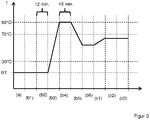
- the ventilation in this method step takes place at a temperature T of the stack sequence 1 between 0° C. and 30° C. and, for example, at room temperature (RT) of the environment. This takes place over a period of time t greater than or equal to 8 minutes and, for example, 12 minutes.
- figure 3 shows an exemplary diagram of the temperature profile during the method according to the invention.
- the horizontal axis is divided into process steps. Both axes are not to scale.
- the stack sequence 1 is transported by the transport device into the first heating area 12 of the device 10.
- the first heating area 12 is, for example, a circulating air oven, in which the stack sequence 1 is heated by a stream of hot air.
- the stack sequence 1 is heated to a temperature T from 70°C to 115°C and heated to e.g. 90°C.
- a step b4) the stack sequence 1 is vented at the temperature T of, for example, 90° C. for a period t of greater than or equal to 8 minutes and, for example, 15 minutes.
- the negative pressure of p 0.1 bar on the vacuum ring is continuously maintained.
- the stack sequence 1 is cooled to a temperature T of less than 70°C, for example to a temperature T of 50°C.
- the negative pressure of p 0.1 bar on the vacuum ring is continuously maintained.
- the cooling can be accelerated by a cooling unit 14, for example by an air flow of air from the surroundings of the device 10 with a fan.
- Cooling under reduced pressure is advantageous since cooling without reduced pressure leads to the formation of bubbles and opacity in the subsequent laminated pane.
- a step b6 the suction effect on the vacuum ring 5 of the stack sequence 1 is switched off and an ambient pressure is applied, as a result of which the vacuum ring 5 is vented. The vacuum ring 5 is then removed from the stack sequence 1.
- the stack sequence 1 is then transferred from the vertical position to a horizontal position, for example by an industrial robot.
- Figure 2B shows a schematic representation of the stacking sequence 1, the second heating area 13 and the calender roller system 17.
- the stacking sequence 1 is here lying horizontally and arranged in the longitudinal direction, i.e. the lower edge U is aligned approximately parallel to the transport direction 20.
- a step c1) the stack sequence 1 is transported by the transport device into the second heating area 13 of the device 10.
- the second heating area 13 is, for example, an oven which is operated by a number of electrically operated radiant heaters made of quartz rods. There, the stack sequence 1 is heated to a temperature T of 40°C to 120°C and, for example, to 60°C.
- the stacking sequence 1 is then introduced into the calender system 17 .
- the calender system 17 consists of at least one first calender unit 16.
- the first calender unit 16 comprises at least two calender rolls 6.1, 6.2 lying opposite one another.
- the first calender unit 16 comprises thirty-five lower calender rolls 6.1 and thirty-five upper calender rolls 6.2, which are each arranged opposite one another.
- the stack sequence 1 is introduced between the lower calender rolls 6.1 and the upper calender rolls 6.2 and pressed together by them.
- the calender rolls 6.1, 6.2 each have a core made of a solid profile made of aluminum.
- the core of the lower calender rolls 6.1 has a diameter of 16 cm, for example, and the core of the upper calender rolls 6.2 has a diameter of 9 cm, for example.
- the lateral surfaces of the calender rolls 6.1, 6.2 each have an elastomer coating 22, for example 2 cm thick, with a Shore A hardness of 70, for example.
- the width of the calender rolls 6.1, 6.2 is 2.6 cm, for example.
- the calender rollers 6.1, 6.2 have the elastomer coating 22 over their entire width, with the elastomer coating 22 having an annular slot with a width of 0.2 cm, for example, in the middle of its width direction, so that the width of the contact surface of the elastomer coating 22 with of the stacking sequence 1 is two times 1.2 cm.
- every fifth lower calender roll 6.1 has a drive which moves the stack sequence 1 on at the speed of the transport unit. It goes without saying that more or fewer calender rolls 6.1 or 6.2 and in particular all calender rolls 6.1, 6.2 can also have a drive.
- the other lower calender rolls 6.1 and the upper calender rolls 6.2 are arranged so as to be rotatable about their central axis and rotate according to the movement of the stack sequence 1.
- Each calender roll 6.1, 6.2 of the first calender unit 16 is advantageously connected to a compressed air cylinder, with which pressure can be exerted on the stack sequence 1 via the calender rolls 6.1, 6.2.
- the operating pressure of the compressed air cylinder is, for example, from 2 bar to 8 bar.
- the contact pressure of the calender rollers 6.1, 6.2 on the surface of the stack sequence 1 is, for example, from 200 N to 950 N.
- the compressed air cylinders can be charged individually or adjacent units of compressed air cylinders can be charged with different pressures. This makes it possible, for example, to exert a higher contact pressure on stack sequence 1 in an edge region r of stack sequence 1 than, for example, in neighboring regions of stack sequence 1. This configuration has the advantage of improved quality of the edge region of the laminated pane produced by the method according to the invention.
- the calender system 17 shown has a second calender unit 18 which is arranged behind the first calender unit 16 in the transport direction 20 .
- the second calender unit 18 consists, for example, of nine pairs of calender rolls 8.1, 8.2, with a lower calender roll 8.1 being arranged opposite an upper calender roll 8.2.
- the calender rolls 8.1, 8.2 are constructed in accordance with the calender rolls 6.1, 6.2, for example. This means that the calender rolls 8.1, 8.2 each have, for example, a core 21 made of a solid profile made of aluminum.
- the core 21 of the lower calender rolls 8.1 has a diameter of 16 cm, for example, and the core of the upper calender rolls 8.2 has a diameter of 9 cm, for example.
- the lateral surfaces of the calender rolls 8.1, 8.2 each have an elastomer coating 22, for example 2 cm thick, with a Shore A hardness of 70, for example.
- the width of the calender rolls 8.1, 8.2 is 2.6 cm, for example.
- the calender rolls 8.1, 8.2 have the elastomer coating 22 over their entire width, the elastomer coating 22 having an annular slit with a width of 0.2 cm, for example, in the middle of its width direction has, so that the width of the contact surface of the elastomeric coating 22 with the stack sequence 1 is two times 1.2 cm.
- Each calender roll 8.1, 8.2 of the second calender unit 18 is advantageously connected to a compressed air cylinder, with which pressure can be exerted on the stack sequence 1 via the calender rolls 8.1, 8.2.
- the operating pressure of the compressed air cylinder is, for example, from 1 bar to 6 bar.
- the contact pressure of the calender rollers 8.1, 8.2 on the surface of the stack sequence 1 is, for example, from 50 N to 700 N.
- the stack sequence 1 after being pressed together by the first calender unit 16, is introduced over its entire surface in method step c2) in a further method step c3) between the calender rollers 8.1, 8.2 of the second calender unit 18.
- the second calender unit 18 now presses together a targeted edge area 7 of width r of, for example, 20 cm along the lower edge of the stack sequence 1 .
- the edge region 7 along the lower edge of the stack sequence 1 or the laminated pane formed thereby often has cloudiness and air inclusions in methods according to the prior art.
- Process step c3) can effectively eliminate these air inclusions and turbidity.
Landscapes
- Physics & Mathematics (AREA)
- Thermal Sciences (AREA)
- Engineering & Computer Science (AREA)
- Mechanical Engineering (AREA)
- Joining Of Glass To Other Materials (AREA)
- Casting Or Compression Moulding Of Plastics Or The Like (AREA)
- Laminated Bodies (AREA)
Description
Die Erfindung betrifft ein Verfahren zur autoklavfreien Lamination einer Verbundscheibe sowie eine Vorrichtung zur Durchführung des erfindungsgemäßen Verfahrens.The invention relates to a method for autoclave-free lamination of a laminated pane and a device for carrying out the method according to the invention.
Verbundscheiben finden vielfach Verwendung, beispielsweise als Fahrzeugscheiben wie Windschutzscheiben, Seitenscheiben, Heckscheiben oder Dachscheiben in Fahrzeugen zu Wasser, zu Lande oder in der Luft, aber auch als Architekturscheiben, als Brandschutzscheiben, als Sicherheitsverglasung oder in Möbeln sowie beweglichen oder festmontierten Einrichtungsgegenständen.Laminated panes are used in many ways, for example as vehicle panes such as windshields, side windows, rear windows or roof panes in vehicles on water, on land or in the air, but also as architectural panes, fire protection panes, safety glazing or in furniture and movable or permanently installed furnishings.
Verbundscheiben umfassen typischerweise zwei Scheiben, beispielsweise eine Substratscheibe und eine Deckscheibe, die über eine Zwischenschicht, beispielsweise aus einer thermoplastischen Polyvinylbutyral (PVB)-Folie in einem Laminationsverfahren unter Einwirkung von Hitze und Druck miteinander verbunden werden.Composite panes typically comprise two panes, for example a substrate pane and a cover pane, which are connected to one another via an intermediate layer, for example made from a thermoplastic polyvinyl butyral (PVB) film, in a lamination process under the action of heat and pressure.
Industriell übliche Laminationsverfahren umfassen dabei in der Regel einen Entlüftungsprozess kombiniert mit einem Autoklavprozess, wie beispielsweise in
Autoklavfreie Laminationsverfahren haben oftmals den Nachteil, dass die Scheiben nur unzureichend miteinander verbunden werden und beispielsweise im Fahrzeugbereich üblichen Anforderungen nicht genügen. Des Weiteren zeigen autoklavfrei laminierte Verbundscheiben oftmals Lufteinschlüsse und Trübungen im Randbereich der Verbundscheibe. Deshalb werden in autoklavfreien Laminationsverfahren oftmals spezielle Zwischenschichten verwendet.Autoclave-free lamination processes often have the disadvantage that the panes are only insufficiently connected to one another and do not meet the usual requirements, for example in the automotive sector. Furthermore, autoclave-free laminated composite panes often show air inclusions and cloudiness in the edge area of the composite pane. Therefore, special intermediate layers are often used in autoclave-free lamination processes.
Die
Die
Die Aufgabe der vorliegenden Erfindung besteht nunmehr darin, ein verbessertes Verfahren zur autoklavfreien Lamination einer Verbundscheibe bereitzustellen, das es ermöglicht kostengünstig Verbundscheiben hoher Qualität herzustellen.The object of the present invention is now to provide an improved method for autoclave-free lamination of a composite pane, which makes it possible to produce composite panes of high quality at low cost.
Die Aufgabe der vorliegenden Erfindung wird erfindungsgemäß durch ein Verfahren zur autoklavfreien Lamination einer Verbundscheibe gemäß dem unabhängigen Anspruch 1 gelöst. Bevorzugte Ausführungsformen gehen aus den Unteransprüchen hervor.The object of the present invention is achieved according to the invention by a method for the autoclave-free lamination of a laminated pane according to
Das erfindungsgemäße Verfahren umfasst zumindest die folgenden Verfahrensschritte: Einen ersten Schritt (a) Herstellen einer Stapelfolge aus einer Substratscheibe, mindestens einer Zwischenschicht und einer Deckscheibe, die durch das erfindungsgemäße Verfahren zu einer Verbundscheibe laminiert wird.The method according to the invention comprises at least the following method steps: A first step (a) producing a stack sequence from a substrate pane, at least one intermediate layer and a cover pane, which is laminated by the method according to the invention to form a composite pane.
Eine Schrittfolge zur Entlüftung der Stapelfolge, umfassend die Schritte:
- (b1) Legen eines Vakuum-Ring oder eines Vakuum-Sack um die Stapelfolge,
- (b2) Entlüften der Stapelfolge
- bei einer Temperatur T von 0°C bis 30°C, bevorzugt bei Raumtemperatur oder Umgebungstemperatur,
- für eine Zeitdauer t von größer oder gleich 8 Minuten (abgekürzt: min), bevorzugt eine Zeitdauer t von 10 min bis 60 min und besonders bevorzugt für eine Zeitdauer t von 10 min bis 20 min und
- durch Anlegen eines absoluten Drucks p von kleiner oder gleich 0,3 bar, bevorzugt von kleiner oder gleich 0,2 bar und besonders bevorzugt von
- (b3) Erwärmen der Stapelfolge auf eine Temperatur T von 70°C bis 115°C, bevorzugt von 80°C bis 100°C, bei einem Druck p von kleiner oder gleich 0,3 bar, bevorzugt von kleiner oder gleich 0,2 bar und besonders bevorzugt von kleiner oder gleich 0,15 bar,
- (b4) Entlüften der Stapelfolge
- für eine Zeitdauer t von größer oder gleich 8 min, bevorzugt eine Zeitdauer t von 10 min bis 60 min und besonders bevorzugt für eine Zeitdauer t von 10 min bis 20 min,
- durch Anlegen eines absoluten Drucks p von kleiner oder gleich 0,3 bar, bevorzugt von kleiner oder gleich 0,2 bar und besonders bevorzugt von kleiner oder gleich 0,15 bar, an den Vakuum-Ring oder den Vakuum-Sack,
- (b5) Abkühlen der Stapelfolge auf eine Temperatur T von kleiner 70°C, und
- (b6) Belüften und Entfernen des Vakuum-Rings oder des Vakuum-Sacks.
- (b1) placing a vacuum ring or a vacuum bag around the stacking sequence,
- (b2) venting the stack sequence
- at a temperature T of 0°C to 30°C, preferably at room temperature or ambient temperature,
- for a period of time t of greater than or equal to 8 minutes (abbreviated: min), preferably a period of time t of 10 minutes to 60 minutes and particularly preferably for a period of time t of 10 minutes to 20 minutes and
- by applying an absolute pressure p of less than or equal to 0.3 bar, preferably less than or equal to 0.2 bar and particularly preferably of
- (b3) heating the stack sequence to a temperature T of 70° C. to 115° C., preferably 80° C. to 100° C., at a pressure p of less than or equal to 0.3 bar, preferably less than or equal to 0.2 bar and particularly preferably less than or equal to 0.15 bar,
- (b4) Venting the stack sequence
- for a period t of greater than or equal to 8 minutes, preferably a period t of 10 minutes to 60 minutes and particularly preferably for a period t of 10 minutes to 20 minutes,
- by applying an absolute pressure p of less than or equal to 0.3 bar, preferably less than or equal to 0.2 bar and particularly preferably less than or equal to 0.15 bar, to the vacuum ring or the vacuum bag,
- (b5) cooling the stack sequence to a temperature T of less than 70°C, and
- (b6) Vent and remove vacuum ring or bag.
Sowie eine weitere Schrittfolge zum Zusammenpressen der Stapelfolge, umfassend die Schritte:
- (c1) Erwärmen der Stapelfolge auf eine Temperatur T von 40°C bis 120°C, bevorzugt von 50°C bis 110°C,
- (c2) Zusammenpressen der Stapelfolge in einer ersten Kalandereinheit zwischen mindestens zwei einander gegenüberliegenden Kalanderwalzen über die gesamte Breite b der Stapelfolge.
- (c1) heating the stack sequence to a temperature T of from 40°C to 120°C, preferably from 50°C to 110°C,
- (c2) Compression of the stack sequence in a first calender unit between at least two opposing calender rolls over the entire width b of the stack sequence.
Einander gegenüberliegend bedeutet im Sinne der vorliegenden Erfindung, dass die zwei Kalanderwalzen bezüglich der Prozessebene, also der Position der Stapelfolge während des Zusammenpressens, einander gegenüberliegen. Das heißt, die eine Kalanderwalze ist auf der einen Seite der Prozessebene (beispielsweise unterhalb der Stapelfolge) angeordnet und die andere Kalanderwalze ist auf der anderen Seite der Prozessebene (beispielsweise oberhalb der Stapelfolge) angeordnet. Hinsichtlich einer orthogonalen Projektion durch die Prozessebene sind die Kalanderwalzen deckungsgleich zueinander angeordnet. Dies bedeutet, dass die jeweiligen Zentren der Kontaktflächen der oberhalb und der unterhalb der Stapelfolge angeordneten Kalanderwalzen mit der jeweiligen Oberfläche der Stapelfolge deckungsgleich zueinander angeordnet sind.Within the meaning of the present invention, opposite one another means that the two calender rolls are opposite one another with regard to the process level, ie the position of the stacking sequence during the pressing together. This means that one calender roll is arranged on one side of the process level (for example below the stacking sequence) and the other calender roll is arranged on the other side of the process level (for example above the stacking sequence). With regard to an orthogonal projection through the process level, the calender rolls are arranged congruently with one another. This means that the respective centers of the contact surfaces of the calender rolls arranged above and below the stacking sequence are arranged congruently with the respective surface of the stacking sequence.
Die Breite b der Stapelfolge ist hier die Richtung senkrecht zur Transportrichtung der Stapelfolge durch die Kalanderwalzen.The width b of the stack sequence is here the direction perpendicular to the transport direction of the stack sequence through the calender rolls.
In einer vorteilhaften Ausführungsform des erfindungsgemäßen Verfahrens wird die Stapelfolge im Verfahrensschritt (b3) innerhalb einer Dauer von 5 min bis 60 min, bevorzugt innerhalb von 10 min bis 35 min auf die Zieltemperatur erwärmt.In an advantageous embodiment of the method according to the invention, the stack sequence in method step (b3) is heated to the target temperature within a period of 5 minutes to 60 minutes, preferably within 10 minutes to 35 minutes.
Eine vorteilhafte Ausführungsform des erfindungsgemäßen Verfahrens umfasst einen an den Verfahrensschritt c2) anschließenden Verfahrensschritt c3), wobei ein Randbereich der Stapelfolge in einer zweiten Kalandereinheit zwischen mindestens zwei weiteren einander gegenüberliegenden Kalanderwalzen zusammengepresst wird.An advantageous embodiment of the method according to the invention comprises a method step c3) following method step c2), wherein an edge region of the stack sequence is pressed together in a second calender unit between at least two further calender rolls lying opposite one another.
Die Breite r des Randbereich, der von den weiteren Kalanderwalzen zusammengepresst wird, beträgt vorteilhafterweise mindestens 1 cm, bevorzugt von 1 cm bis 50% der Breite b der Stapelfolge und besonders bevorzugt von 2 cm bis 30% der Breite b der Stapelfolge. Die Breite b der Stapelfolge ist hier definiert, als die Breite orthogonal zur Transportrichtung der Stapelfolge, das heißt orthogonal zur Transportrichtung durch die erfindungsgemäße Vorrichtung.The width r of the edge area, which is pressed together by the further calender rolls, is advantageously at least 1 cm, preferably from 1 cm to 50% of the width b of the stack sequence and particularly preferably from 2 cm to 30% of the width b of the stack sequence. The width b of the stacking sequence is defined here as the width orthogonal to the transport direction of the stacking sequence, ie orthogonal to the transport direction through the device according to the invention.
Dies hat den besonderen Vorteil, dass die Stapelfolge im Randbereich besonders gut miteinander verbunden wird. Insbesondere trapezförmige und/oder leicht gebogene Stapelfolgen können eine Biegeabweichung zwischen der Biegung der Substratscheibe und der Deckscheibe aufweisen. Diese Biegeabweichung ist im Randbereich besonders groß. Bei trapezförmigen Verbundscheiben ist die Biegeabweichung im Randbereich der Unterkante, also im Randbereich der längeren Grundseite der trapezförmigen Scheibe besonders groß und neigt zum Einschluss von Luftblasen oder Trübungen. Der zusätzliche Schritt c3) führt zu einer besonders innigen Verbindung zwischen Substratscheibe und Deckscheibe in diesem kritischen Bereich und daher zu einer besonders guten Scheibenqualität.This has the particular advantage that the stacking sequence is connected to one another particularly well in the edge area. In particular, trapezoidal and/or slightly curved stacking sequences can exhibit a bending deviation between the bending of the substrate pane and the cover pane. This bending deviation is particularly large in the edge area. In the case of trapezoidal composite panes, the bending deviation in the edge area of the lower edge, i.e. in the edge area of the longer base of the trapezoidal pane, is particularly large and tends to trap air bubbles or cloudiness. The additional step c3) leads to a particularly intimate connection between the substrate disk and the cover disk in this critical area and therefore to a particularly good disk quality.
In einer alternative vorteilhafte Ausführungsform des erfindungsgemäßen Verfahrens wird im Verfahrensschritt c2) die Stapelfolge durch eine oder mehrere einander gegenüberliegende Kalanderwalzen der ersten Kalandereinheit des Randbereich mit einem höheren Anpressdruck zusammengepresst als im übrigen Bereich. Dazu ist es notwendig, dass die Kalanderwalzen einzeln oder in Gruppen mit unterschiedlichen Anpressdrücken beaufschlagt werden können. Auch dies führt zu einer besonders innigen Verbindung zwischen Substratscheibe und Deckscheibe in dem, wie oben erläutert, kritischen Randbereich der Verbundscheibe und daher zu einer besonders guten Scheibenqualität. Es versteht sich, dass diese Ausführungsform des erfindungsgemäßen Verfahrens auch von dem Verfahrensschritt c3) gefolgt werden kann und die Qualität der Verbundscheibe dadurch nochmals verbessert werden kann.In an alternative advantageous embodiment of the method according to the invention, in method step c2) the stack sequence is pressed together by one or more opposing calender rolls of the first calender unit in the edge area with a higher contact pressure than in the remaining area. For this it is necessary that the calender rolls can be applied individually or in groups with different contact pressures. This also leads to a particularly intimate connection between the substrate pane and the cover pane in the critical edge area of the composite pane, as explained above, and therefore to a particularly good pane quality. It is understood that this embodiment of the method according to the invention can also be followed by method step c3) and the quality of the laminated pane can thereby be further improved.
Als Substratscheibe und Deckscheibe sind im Grunde alle elektrisch isolierenden Substrate geeignet, die unter den Bedingungen der Herstellung und der Verwendung der erfindungsgemäßen Verbundscheibe thermisch und chemisch stabil sowie dimensionsstabil sind.In principle, all electrically insulating substrates that are thermally and chemically stable and dimensionally stable under the conditions of production and use of the composite pane according to the invention are suitable as the substrate pane and cover pane.
Die Substratscheibe und/oder die Deckscheibe enthalten bevorzugt Glas, besonders bevorzugt Flachglas, ganz besonders bevorzugt Floatglas und insbesondere Quarzglas, Borosilikatglas, Kalk-Natron-Glas, oder besteht daraus. Alternative Substratscheiben und/oder Deckscheiben enthalten bevorzugt klare Kunststoffe, besonders bevorzugt starre klare Kunststoffe und insbesondere Polyethylen, Polypropylen, Polycarbonat, Polymethylmethacrylat, Polystyrol, Polyamid, Polyester, Polyvinylchlorid und/oder Gemische davon, oder bestehen daraus. Es versteht sich, dass auch eine der Scheiben Glas und die andere Scheibe Kunststoff enthalten oder daraus bestehen kann. Das Substrat und/oder die Deckscheibe sind bevorzugt transparent, insbesondere für die Verwendung der Scheibe als Windschutzscheide oder Rückscheibe eines Fahrzeugs oder anderen Verwendungen bei denen eine hohe Lichttransmission erwünscht ist. Als transparent im Sinne der Erfindung wird dann eine Scheibe verstanden, die eine Transmission im sichtbaren Spektralbereich von größer 70 % aufweist. Für Scheiben, die nicht im verkehr-relevanten Sichtfeld des Fahrers liegen, beispielsweise für Dachscheiben, kann die Transmission aber auch viel geringer sein, beispielsweise größer als 5 %.The substrate pane and/or the cover pane preferably contain or consist of glass, particularly preferably flat glass, very particularly preferably float glass and in particular quartz glass, borosilicate glass, soda-lime glass. Alternative substrate discs and/or cover discs preferably contain or consist of clear plastics, particularly preferably rigid clear plastics and in particular polyethylene, polypropylene, polycarbonate, polymethyl methacrylate, polystyrene, polyamide, polyester, polyvinyl chloride and/or mixtures thereof. It goes without saying that one of the panes can also contain glass and the other pane can contain or consist of plastic. The substrate and/or the cover pane are preferably transparent, in particular for use of the pane as a windshield or rear pane of a vehicle or other uses where high light transmission is desired. A pane that has a transmission in the visible spectral range of more than 70% is then understood to be transparent within the meaning of the invention. However, for panes that are not in the driver's field of vision relevant to traffic, for example for roof panes, the transmission can also be much lower, for example greater than 5%.
Die Dicke von Substrat und/oder Deckscheibe kann breit variieren und so hervorragend den Erfordernissen des Einzelfalls angepasst werden. Vorzugsweise werden Standardstärken von 1,0 mm bis 25 mm, bevorzugt von 1,4 mm bis 2,5 mm für Fahrzeugglas und bevorzugt von 4 mm bis 25 mm für Möbel, Geräte und Gebäude, insbesondere für elektrische Heizkörper, verwendet. Die Größe der Scheibe kann breit variieren und richtet sich nach der Größe der erfindungsgemäßen Verwendung. Das Substrat und gegebenenfalls die Deckscheibe weisen beispielsweise im Fahrzeugbau und Architekturbereich übliche Flächen von 200 cm2 bis zu 20 m2 auf.The thickness of the substrate and/or cover plate can vary widely and can thus be perfectly adapted to the requirements of the individual case. Standard thicknesses of 1.0 mm to 25 mm, preferably 1.4 mm to 2.5 mm for vehicle glass and preferably 4 mm to 25 mm for furniture, appliances and buildings, in particular for electric heaters, are preferably used. The size of the disc can vary widely and depends on the size of the use according to the invention. The substrate and optionally the cover pane have areas of 200 cm 2 up to 20 m 2 , which are common in vehicle construction and architecture, for example.
Die Verbundscheibe kann eine beliebige dreidimensionale Form aufweisen. Vorzugsweise hat die dreidimensionale Form keine Schattenzonen, so dass sie beispielsweise durch Kathodenzerstäubung beschichtet werden kann. Bevorzugt sind die Substrate planar oder leicht oder stark in einer Richtung oder in mehreren Richtungen des Raumes gebogen. Insbesondere werden planare Substrate verwendet. Die Scheiben können farblos oder gefärbt sein.The composite pane can have any three-dimensional shape. Preferably, the three-dimensional shape has no shadow zones, so that, for example can be coated by cathode sputtering. Preferably, the substrates are planar or slightly or greatly curved in one or more directions of space. In particular, planar substrates are used. The discs can be colorless or colored.
Substrate und/oder Deckscheiben werden durch mindestens eine Zwischenschicht miteinander verbunden. Die Zwischenschicht ist bevorzugt transparent. Die Zwischenschicht enthält vorzugsweise mindestens einen Kunststoff, bevorzugt Polyvinylbutyral (PVB), Ethylenvinylacetat (EVA) und / oder Polyethylenterephthalat (PET). Die Zwischenschicht kann aber auch beispielsweise Polyurethan (PU), Polypropylen (PP), Polyacrylat, Polyethylen (PE), Polycarbonat (PC), Polymethylmethacrylat, Polyvinylchlorid, Polyacetatharz, Gießharze, Acrylate, fluorinierte Ethylen-Propylene, Polyvinylfluorid und/oder Ethylen-Tetrafluorethylen, oder Copolymere oder Gemische davon enthalten.Substrates and/or cover sheets are connected to one another by at least one intermediate layer. The intermediate layer is preferably transparent. The intermediate layer preferably contains at least one plastic, preferably polyvinyl butyral (PVB), ethylene vinyl acetate (EVA) and/or polyethylene terephthalate (PET). However, the intermediate layer can also be, for example, polyurethane (PU), polypropylene (PP), polyacrylate, polyethylene (PE), polycarbonate (PC), polymethyl methacrylate, polyvinyl chloride, polyacetate resin, casting resins, acrylates, fluorinated ethylene-propylene, polyvinyl fluoride and/or ethylene-tetrafluoroethylene , or contain copolymers or mixtures thereof.
Die Zwischenschicht kann durch eine oder auch durch mehrere übereinander angeordnete Folien ausgebildet werden, wobei die Dicke einer Folie bevorzugt von 0,025 mm bis 1 mm beträgt, typischerweise 0,38 mm oder 0,76 mm. Das heißt die Zwischenschicht kann jeweils aus einer oder aus mehreren Folien aufgebaut sein. Bevorzugt sind dabei mindestens drei übereinander angeordnete Folien, insbesondere Polvyinybutyral-Folien, mit alternierender unterschiedlicher Plastizität oder Elastizität, wie sie beispielsweise aus der
Die Zwischenschichten können bevorzugt thermoplastisch sein und nach der Lamination das Substrat, die Deckscheibe und eventuelle weitere Zwischenschichten miteinander verkleben.The intermediate layers can preferably be thermoplastic and, after lamination, can bond the substrate, the cover pane and any other intermediate layers to one another.
Das erfindungsgemäße Verfahren ist besonders geeignet Zwischenschichten aus einer oder mehreren Polyvinylbutyral-Folien zu verarbeiten. Die Oberfläche der Polyvinylbutyral-Folie kann dabei geprägt sein und eine beliebige Rauigkeit aufweisen. Besonders bevorzugt sind Polyvinylbutyral-Folien mit einer Rauigkeit Rz von 15 µm bis 90 µm. Rz ist hier definiert als die gemittelte Rautiefe, also der Summe aus der Höhe der größten Profilspitze und der Tief des größten Profiltals innerhalb einer Einzelmessstrecke Ir.The method according to the invention is particularly suitable for processing intermediate layers made from one or more polyvinyl butyral films. The surface of the polyvinyl butyral film can be embossed and have any roughness. Polyvinyl butyral films with a roughness R z of 15 μm to 90 μm are particularly preferred. R z is defined here as the mean roughness depth, i.e. the sum of the height of the largest profile peak and the bottom of the largest profile valley within a single measurement section I r .
In einer vorteilhaften Ausführungsform des erfindungsgemäßen Verfahrens wird als Zwischenschicht eine Polyvinylbutyral-Folie mit einem Wassergehalt von größer oder gleich 0,35 Gew.-% bezogen auf die Masse der Folie verwendet, bevorzugt mit einem Wassergehalt von größer oder gleich 0,4 Gew.-% und besonders bevorzugt mit einem Wassergehalt von größer oder gleich 0,45 Gew.-%. Die Polyvinylbutyral-Folien sind insbesondere silanfrei.In an advantageous embodiment of the method according to the invention, a polyvinyl butyral film with a water content of greater than or equal to 0.35% by weight, based on the mass of the film, is used as the intermediate layer, preferably with a water content of greater than or equal to 0.4% by weight. % and particularly preferably with a water content of greater than or equal to 0.45% by weight. In particular, the polyvinyl butyral films are silane-free.
Damit ist das erfindungsgemäße Verfahren dazu geeignet eine im industrielle Standard-PVB-Folie mit einem Wassergehalt von ≥0,4 Gew.-% und ohne spezielle Silan-haltige Haftverstärker zu verwenden. Derartige Folien sind besonders kostengünstig und industriell gut zu verarbeiten. Im Gegensatz zu Verfahren nach dem Stand der Technik, sind bei dem erfindungsgemäßen Verfahren keine speziellen auf das Verfahren abgestimmte Folien notwendig. Das erfindungsgemäße Verfahren ist universell einsetzbar und kann mit den angegeben Folien besonders gute Resultate erzielen.The method according to the invention is therefore suitable for using an industrial standard PVB film with a water content of ≧0.4% by weight and without special silane-containing adhesion promoters. Such films are particularly inexpensive and easy to process industrially. In contrast to processes according to the state of the art, with the process according to the invention no special foils tailored to the process are necessary. The method according to the invention can be used universally and can achieve particularly good results with the films indicated.
Des Weiteren muss die Stapelfolge lediglich auf maximal 90°C bis 115°C erhitzt werden und nicht auf höhere Temperaturen, wie im Stand der Technik. Das erfindungsgemäße Walzenverfahren ist besonderes energiesparend. Das erfindungsgemäße Verfahren mit einer Kombination aus einem vergleichsweise Kühlen Vakuumverfahren und eine besonders engiesparenden Walzenverfahren benötigt insgesamt nur wenig Energie und ist besonders kostengünstig.Furthermore, the stack sequence only has to be heated to a maximum of 90° C. to 115° C. and not to higher temperatures, as is the case in the prior art. The rolling method according to the invention is particularly energy-saving. The method according to the invention with a combination of a comparatively cool vacuum method and a particularly energy-saving roller method requires little energy overall and is particularly cost-effective.
In einer vorteilhaften Ausführungsform wird die gesamte Herstellung der Verbundscheibe autoklavfrei durchgeführt. Das erfindungsgemäße Verfahren ist deshalb besonders energiesparend und kostengünstig.In an advantageous embodiment, the entire production of the composite pane is carried out without an autoclave. The method according to the invention is therefore particularly energy-saving and inexpensive.
In einer vorteilhaften Ausführungsform des erfindungsgemäßen Verfahrens, wird während der Verfahrensschritte (b2) bis (b5) kontinuierlich ein Unterdruck an den Vakuum-Ring oder den Vakuum-Sack angelegt. Bevorzugt wird ununterbrochen ein Druck p von kleiner oder gleich 0,3 bar angelegt. Dies gilt insbesondere bei Verwendung eines Vakuum-Rings. Aus technischen Gründen kann es nötig sein, dass die Unterdruckleitung kurzzeitig entfernt wird, insbesondere bei Verwendung eines Vakuum-Sacks. Der Vakuum-Ring und der Vakuum-Sack weisen Ventile auf, die bei Abkoppeln der Unterdruckleitung das Vakuum im Ring oder Sack aufrechterhalten. Ein Abkoppeln kann nötig sein, um die Stapelfolge zu transportieren, insbesondere von einer Station zur nächsten. Durch Undichtigkeiten im System Ring/Sack-Stapelfolge und durch Ausgasung aus der Stapelfolge kann sich der Druck erhöhen. Bevorzugt bleibt der Druck p auch während der Abkoppelphasen kleiner oder gleich 0,8 bar, besonders bevorzugt kleiner oder gleich 0,7 bar und insbesondere kleiner oder gleich 0,6 bar. Es hat sich gezeigt, dass ein kurzes Abkoppeln und eine kurze Druckerhöhung die Ergebnisse nicht wesentlich verschlechtert.In an advantageous embodiment of the method according to the invention, a negative pressure is continuously applied to the vacuum ring or the vacuum bag during method steps (b2) to (b5). A pressure p of less than or equal to 0.3 bar is preferably applied continuously. This applies in particular when using a vacuum ring. For technical reasons, it may be necessary to temporarily remove the vacuum line, especially when using a vacuum bag. The vacuum ring and vacuum bag have valves that maintain the vacuum in the ring or bag when the vacuum line is disconnected. Undocking may be necessary to transport the stacking sequence, particularly from one station to the next. The pressure can increase as a result of leaks in the ring/bag stack sequence system and outgassing from the stack sequence. The pressure p preferably remains less than or equal to 0.8 bar, particularly preferably less than or equal to 0.7 bar and in particular less than or equal to 0.6 bar, even during the decoupling phases. It has been shown that a short decoupling and a short increase in pressure does not significantly worsen the results.
Ein weiterer Aspekt der Erfindung umfasst eine Vorrichtung zur Durchführung des Verfahrens, mindestens umfassend:
- eine Transporteinrichtung zum Verfahren der Stapelfolge durch die Vorrichtung entlang einer Transportrichtung,
- ein Vakuumsystem mit mindestens einem Vakuum-Ring oder mindestens einem Vakuum-Sack zum Entlüften der Stapelfolge in den Verfahrensschritten b2) und b4),
- einen ersten Heizbereich zum Erwärmen der Stapelfolge (1) in Verfahrensschritt b3),
- einen zweiten Heizbereich, der in Transportrichtung hinter dem ersten Heizbereich angeordnet ist, zum Erwärmen der Stapelfolge im Verfahrensschritt c1),
- ein Kalanderwalzensystem, das in Transportrichtung im oder hinter dem zweiten Heizbereich angeordnet ist, und eine erste Kalandereinheit mit mindestens zwei einander gegenüberliegenden Kalanderwalzen umfasst, zum Zusammenpressen der Stapelfolge im Verfahrensschritt c2),
- das Kalanderwalzensystem eine zweite Kalendereinheit zum Zusammenpressen der Stapelfolge im Verfahrensschritt c3) umfasst, die in Transportrichtung der Stapelfolge hinter der ersten Kalandereinheit angeordnet ist und die mindestens zwei einander gegenüberliegenden Kalanderwalzen aufweist, und/oder
- die Kalanderwalzen derart ausgebildet sind, dass die Stapelfolge in einem Randbereich mit einem höheren Anpressdruck zusammengepresst werden kann, als im übrigen Bereich.
- a transport device for moving the stack sequence through the device along a transport direction,
- a vacuum system with at least one vacuum ring or at least one vacuum bag for venting the stack sequence in process steps b2) and b4),
- a first heating area for heating the stack sequence (1) in method step b3),
- a second heating area, which is arranged behind the first heating area in the transport direction, for heating the stack sequence in method step c1),
- a calender roller system, which is arranged in the transport direction in or behind the second heating area, and comprises a first calender unit with at least two opposing calender rollers, for pressing the stack sequence together in method step c2),
- the calender roller system comprises a second calender unit for pressing the stack sequence together in method step c3), which is arranged behind the first calender unit in the transport direction of the stack sequence and has at least two calender rollers opposite one another, and/or
- the calender rollers are designed in such a way that the stack sequence can be pressed together in an edge area with a higher contact pressure than in the remaining area.
Sowohl der erste Heizbereich als auch der zweite Heizbereich, können jeweils aus einem Bereich oder mehreren in Transportrichtung hintereinander angeordneten Unterheizbereichen ausgebildet sein. Es versteht sich, dass der erste Heizbereich oder die Summe der ersten Unterheizbereiche im Bereich des Vakuumsystems angeordnet ist beziehungsweise sind. Des Weiteren versteht es sich, dass der zweite Heizbereich oder die Summe der zweiten Unterheizbereiche im Bereich des Kalanderwalzensystems angeordnet ist beziehungsweise sind.Both the first heating area and the second heating area can each be formed from one area or from a plurality of sub-heating areas arranged one behind the other in the direction of transport. It goes without saying that the first heating area or the sum of the first sub-heating areas is or are arranged in the area of the vacuum system. Furthermore, it goes without saying that the second heating area or the sum of the second sub-heating areas is or are arranged in the area of the calender roller system.
Die Heizbereiche können durch alle technisch sinnvollen Heizvorrichtungen betrieben werden, beispielsweise durch einen oder mehrere elektrisch betriebene Heizstrahler, beispielsweise aus Quarzstäben, durch andere geeignete Strahlungsquellen, wie Mikrowellenstrahlern, durch Konvektionsöfen, Umluftöfen oder durch Heißluftströme.The heating areas can be operated with all technically sensible heating devices, for example with one or more electrically operated radiant heaters, for example from quartz rods, by other suitable sources of radiation, such as microwave radiators, by convection ovens, circulating air ovens or by hot air streams.
In einer Ausgestaltung der erfindungsgemäßen Vorrichtung umfasst das Kalanderwalzensystem eine zweite Kalandereinheit zum Zusammenpressen der Stapelfolge im Verfahrensschritt c3), wobei die die zweite Kalandereinheit in Transportrichtung der Stapelfolge hinter der ersten Kalandereinheit angeordnet ist und mindestens zwei einander gegenüberliegenden Kalanderwalzen aufweist.In one embodiment of the device according to the invention, the calender roller system comprises a second calender unit for pressing the stack sequence together in method step c3), the second calender unit being arranged behind the first calender unit in the transport direction of the stack sequence and having at least two opposite calender rollers.
In einer weiteren Ausgestaltung der erfindungsgemäßen Vorrichtung wird die Stapelfolge in einem Randbereich stärker zusammengepresst, als im übrigen Bereich. Der übrige Bereich ist der Bereich zwischen den Randbereichen. In einer weiteren erfindungsgemäßen Vorrichtung sind die Kalanderwalzen der ersten Kalandereinheit derart ausgebildet, dass die Stapelfolge in einem Randbereich mit einem höheren Anpressdruck zusammengepresst werden kann als im übrigen, mittleren Bereich. Dazu können einzelne Kalanderwalzen oder auch größere Abschnitte von Kalanderwalzen höhere Drücke auf bestimmte Bereiche der Stapelfolge ausüben, beispielsweise durch eine hydraulische Steuerung.In a further embodiment of the device according to the invention, the stack sequence is pressed together more strongly in an edge area than in the remaining area. The remaining area is the area between the edge areas. In a further device according to the invention, the calender rollers of the first calender unit are designed in such a way that the stack sequence can be pressed together in an edge area with a higher contact pressure than in the rest of the middle area. For this purpose, individual calender rolls or also larger sections of calender rolls can exert higher pressures on certain areas of the stacking sequence, for example by means of a hydraulic control.
In einer weiteren erfindungsgemäßen Vorrichtung sind die Kalanderwalzen der zweiten Kalandereinheit derart ausgebildet, dass die Stapelfolge in einem Randbereich mit einem höheren Anpressdruck zusammengepresst werden kann als im übrigen, mittleren Bereich.In a further device according to the invention, the calender rollers of the second calender unit are designed in such a way that the stack sequence can be pressed together in an edge area with a higher contact pressure than in the rest of the middle area.
In einer weiteren erfindungsgemäßen Vorrichtung sind die Kalanderwalzen der zweiten Kalandereinheit nur in einem Bereich angeordnet, in dem der Randbereich der Stapelfolge durch die zweite Kalandereinheit geführt wird.In a further device according to the invention, the calender rollers of the second calender unit are arranged only in a region in which the edge region of the stacking sequence is guided through the second calender unit.
Es versteht sich, dass eine Vorrichtung mit erhöhtem Anpressdruck der ersten Kalandereinheit im Randbereich der Stapelfolge auch mit einer zweiten erfindungsgemäßen Kalandereinheit kombiniert werden kann.It goes without saying that a device with increased contact pressure of the first calender unit in the edge region of the stack sequence can also be combined with a second calender unit according to the invention.
Eine vorteilhafte Ausgestaltung der erfindungsgemäßen Vorrichtung weist mindestens eine Kühleinheit auf, bevorzugt ein Gebläse mit oder ohne Wärmetauscher. Die Kühleinheit ist in Transportrichtung zwischen dem ersten Heizbereich und dem zweiten Heizbereich angeordnet. Dies hat den besonderen Vorteil, dass die Stapelfolge im Verfahrensschritt b4) schnell auf die geforderte Temperatur abgekühlt werden kann, was zu einer Verkürzung der Prozesszeit führt.An advantageous embodiment of the device according to the invention has at least one cooling unit, preferably a fan with or without a heat exchanger. The cooling unit is arranged between the first heating area and the second heating area in the transport direction. This has the particular advantage that the stack sequence can be quickly cooled to the required temperature in method step b4), which leads to a reduction in the process time.
In einer vorteilhaften Ausgestaltung der erfindungsgemäßen Vorrichtung weist die Kalanderwalze einen kreisrunden Kern auf, bevorzugt aus einem Hohlprofil, besonders bevorzugt mit Speichen oder Stützstreben, oder einem Vollprofil. Der Kern enthält bevorzugt ein Metall wie Aluminium oder Edelstahl oder besteht daraus.In an advantageous embodiment of the device according to the invention, the calender roller has a circular core, preferably made of a hollow profile, particularly preferably with spokes or support struts, or a solid profile. The core preferably contains or consists of a metal such as aluminum or stainless steel.
Der Kern hat bevorzugt einen Durchmesser von 5 cm bis 30 cm. In einer vorteilhaften Ausgestaltung weisen die einander gegenüberliegenden Kalanderwalzen Kerne mit unterschiedlichen Durchmessern auf. So betragen die Durchmesser der relativ zur Stapelfolge auf einer Seite angeordneten Kerne von 5 cm bis 10 cm und die Durchmesser der relativ zur Stapelfolge auf der gegenüberliegenden Seite angeordneten Kerne von 12 cm bis 30 cm.The core preferably has a diameter of 5 cm to 30 cm. In an advantageous embodiment, the opposing calender rolls have cores with different diameters. The diameters of the cores arranged on one side relative to the stacking sequence are from 5 cm to 10 cm and the diameters of the cores arranged on the opposite side relative to the stacking sequence are from 12 cm to 30 cm.
Auf der Mantelfläche des Kerns ist mindestens eine Elastomerbeschichtung angeordnet. Die Elastomerbeschichtung weist bevorzugt eine konstante Schichtdicke auf, besonders bevorzugt eine Schichtdicke von 5 mm bis 30 mm, insbesondere von 10 mm bis 25 mm.At least one elastomer coating is arranged on the lateral surface of the core. The elastomer coating preferably has a constant layer thickness, particularly preferably a layer thickness of 5 mm to 30 mm, in particular 10 mm to 25 mm.
Die Kalanderwalze hat bevorzugt eine Breite von 0,9 cm bis 20 cm, bevorzugt von 1,8 cm bis 5 cm. Die Elastomerbeschichtung ist bevorzugt auf der gesamten Breite der Kalanderwalze mantelförmig angeordnet. Die Elastomerbeschichtung kann aber auch aus zwei oder mehreren Mantelbereichen mit entsprechend kleinerer Breite sein, die ringförmig um den Kern angeordnet sind. Dies ist besonders vorteilhaft um auch auf gebogene Stapelfolgen den Anpressdruck gleichmäßig zu verteilen.The calender roll preferably has a width of 0.9 cm to 20 cm, preferably 1.8 cm to 5 cm. The elastomer coating is preferably arranged in the form of a jacket over the entire width of the calender roll. However, the elastomeric coating can also consist of two or more jacket regions with a correspondingly smaller width, which are arranged in a ring around the core. This is particularly advantageous for evenly distributing the contact pressure on curved stack sequences.
Die erfindungsgemäße Elastomerbeschichtung weist vorteilhafterweise eine Shore-A-Härte von 40 bis 90 gemäß DIN EN ISO 868 und DIN ISO 7619-1 auf. Derartige Elastomerbeschichtungen sind besonders dazu geeignet, eine gute Kraftübertragung von der Kalanderwalze zu der Oberfläche Stapelfolge zu gewährleisten ohne durch punktuelle Kraftspitzen die Scheiben der Stapelfolge zu beschädigen.The elastomer coating according to the invention advantageously has a Shore A hardness of 40 to 90 in accordance with DIN EN ISO 868 and DIN ISO 7619-1. Elastomer coatings of this type are particularly suitable for ensuring good power transmission from the calender roll to the surface of the stack sequence without damaging the discs of the stack sequence as a result of point force peaks.
Derartige Kalanderwalzen der ersten Kalandereinheit werden bevorzugt mit einem Anpressdruck von 100 N bis 1000 N, bevorzugt von 200 N bis 950 N, auf die Oberfläche der Stapelfolge gepresst.Such calender rolls of the first calender unit are preferably pressed onto the surface of the stack sequence with a contact pressure of 100 N to 1000 N, preferably 200 N to 950 N.
Derartige Kalanderwalzen der zweiten Kalandereinheit werden bevorzugt mit einem Anpressdruck von 50 N bis 1000 N, besonders bevorzugt von 100 N bis 700 N auf die Oberfläche der Stapelfolge gepresst.Such calender rolls of the second calender unit are preferably pressed onto the surface of the stack sequence with a contact pressure of 50 N to 1000 N, particularly preferably 100 N to 700 N.
Ein weiterer Aspekt der Erfindung umfasst die Verwendung des erfindungsgemäßen Verfahrens zur Herstellung einer Verbundscheibe für Fortbewegungsmittel für den Verkehr auf dem Lande, in der Luft oder zu Wasser, insbesondere in Kraftfahrzeugen Zügen, Flugzeugen oder Schiffen, beispielsweise als Windschutzscheibe, Heckscheibe, Seitenscheibe und/oder Dachscheibe, für Gebäude, insbesondere im Zugangsbereich, Fensterbereich, Dachbereich oder Fassadenbereich, als Einbauteil in Möbeln und Geräten.A further aspect of the invention includes the use of the method according to the invention for producing a laminated pane for means of transport for traffic on land, in the air or on water, in particular in motor vehicles, trains, airplanes or ships, for example as a windshield, rear window, side window and/or Roof pane, for buildings, in particular in the entrance area, window area, roof area or facade area, as a built-in part in furniture and equipment.
Im Folgenden wird die Erfindung anhand einer Zeichnung und Ausführungsbeispielen näher erläutert. Die Zeichnung ist eine schematische Darstellung und nicht maßstabsgetreu. Die Zeichnung schränkt die Erfindung in keiner Weise ein.The invention is explained in more detail below with reference to a drawing and exemplary embodiments. The drawing is a schematic representation and not to scale. The drawing does not limit the invention in any way.
Es zeigen:
Figur 1- ein Flussdiagramm einer Ausführungsform des erfindungs-gemäßen Verfahrens,
- Figur 2A
- eine perspektivische Darstellung eines Ausschnitts der erfindungsgemäßen Vorrichtung,
- Figur 2B
- eine perspektivische Darstellung eines weiteren Ausschnitts der erfindungsgemäßen Vorrichtung und
- Figur 3
- Beispiel eines Temperaturverlaufsdiagramms.
- figure 1
- a flowchart of an embodiment of the method according to the invention,
- Figure 2A
- a perspective view of a section of the device according to the invention,
- Figure 2B
- a perspective view of a further section of the device according to the invention and
- figure 3
- Example of a temperature curve diagram.
In einem ersten Schritt a) des erfindungsgemäßen Verfahrens wird eine Stapelfolge 1 aus beispielsweise einer Substratscheibe 2, einer Zwischenschicht 3 und einer Deckscheibe 4 hergestellt. Die aus der Stapelfolge 1 durch autoklavfreie Lamination herzustellende Verbundscheibe ist beispielsweise eine Windschutzscheibe eines Personenkraftwagens.In a first step a) of the method according to the invention, a
Die Substratscheibe 2 und die Deckscheibe 4 sind in diesem Beispiel jeweils annähernd trapezförmig und weisen eine leichte Wölbung auf, wie sie für moderne Windschutzscheiben üblich ist. Die Substratscheibe 2 und die Deckscheibe 4 sind in diesem Beispiel gleich groß und deckungsgleich übereinander angeordnet. Die Substratscheibe 2 und die Deckscheibe 4 haben eine Breite von beispielsweise 0,9 m und eine Länge an der Unterkante U, das heißt an der längeren Grundseite der trapezförmigen Scheiben, von beispielsweise 1,5 m. Die der Unterkante U gegenüberliegende Kante hat eine Länge von beispielsweise 1,2 m. Es versteht sich, dass bei der Lamination von Verbundscheiben von beispielsweise Seitenscheiben oder Dachscheiben, kleinere oder größere, sowie dreiecksförmig mit komplexen Ausbuchtungen oder rechteckförmige Substratscheiben 2 und Deckscheiben 4 verwendet werden können.In this example, the substrate pane 2 and the cover pane 4 are each approximately trapezoidal and have a slight curvature, as is usual for modern windshields. In this example, the substrate disk 2 and the cover disk 4 are of the same size and are arranged congruently one above the other. The substrate disk 2 and the cover disk 4 have a width of, for example, 0.9 m and a length at the lower edge U, that is, at the longer base side of the trapezoidal disks, of, for example, 1.5 m. The edge opposite the lower edge U has a length of 1.2 m, for example. It goes without saying that when laminating composite panes, for example side panes or roof panes, smaller or larger, as well as triangular with complex bulges or rectangular substrate panes 2 and cover panes 4 can be used.
Die Substratscheibe 2 ist beispielsweise dafür vorgesehen, in Einbaulage dem Innenraum des Fahrzeugs zugewandt zu sein, wogegen die Deckscheibe 4 dafür vorgesehen ist bezüglich des Fahrzeuginnenraums nach außen weist. Substratscheibe 2 und Deckscheibe 4 bestehen beispielsweise aus Natron-Kalkglas. Die Dicke der Substratscheibe 2 beträgt beispielsweise 1,6 mm und die Dicke der Deckscheibe 4 beträgt 2,1 mm. Es versteht sich, dass Substratscheibe 2 und Deckscheibe 4 beispielsweise auch gleich dick ausgebildet sein können. Die Zwischenschicht 3 ist eine thermoplastische Zwischenschicht und besteht beispielsweise aus Polyvinylbutyral (PVB). Sie weist beispielsweise eine Dicke von 0,76 mm bis 0,86 mm auf.The substrate pane 2 is intended, for example, to face the interior of the vehicle in the installed position, whereas the cover pane 4 is intended to point outwards with respect to the vehicle interior. The substrate disk 2 and the cover disk 4 consist, for example, of soda-lime glass. The thickness of the substrate disk 2 is 1.6 mm, for example, and the thickness of the cover disk 4 is 2.1 mm. It goes without saying that the substrate disk 2 and cover disk 4 can also be of the same thickness, for example. The intermediate layer 3 is a thermoplastic intermediate layer and consists, for example, of polyvinyl butyral (PVB). For example, it has a thickness of 0.76 mm to 0.86 mm.
In einem Schritt b1) des erfindungsgemäßen Verfahrens wird ein Vakuum-Ring 5 um die äußeren Seitenkanten der Stapelfolge 1 gelegt. Der Vakuum-Ring 5 ("greensnake") besteht aus einem unterdruckstabilen Schlauch, der die Form eines geschlossenen Rings hat und an seiner Innenseite einen Schlitz aufweist, in den die äußere Seitenkante der Stapelfolge 1 eingelegt ist. Der Vakuum-Ring 5 umschließt die Seitenkanten und den Zwischenraum zwischen der Substratscheibe 2 und der Deckscheibe 4 vollständig und dichtet ihn vakuumtechnisch ab. Der Vakuum-Ring 5 ist über einen Unterdruckschlauch mit einem optionalen Vakuum-Kompensationstank und einer Vakuum-Pumpe verbunden. Vakuum-Ring 5, Unterdruckschlauch, gegebenenfalls Vakuum-Kompensationstank und Vakuum-Pumpe bilden ein Vakuumsystem 15. Der Vakuum-Kompensationstank hat beispielsweise ein Volumen von 1 m3. Die Vakuum-Pumpe hat beispielsweise eine Förderkapazität von 300 m3/h und erreicht einen maximalen Enddruck von 0,1 mbar.In a step b1) of the method according to the invention, a
In der
In einem weiteren Schritt b2) wird die Stapelfolge 1 durch Anlegen eines Unterdrucks von beispielsweise p = 0,1 bar entlüftet. Die Druckangaben beziehen sich auf den absoluten Druck, also den Druck gegenüber dem absoluten Vakuum mit p = 0 bar. Die Entlüftung in diesem Verfahrensschritt erfolgt bei einer Temperatur T der Stapelfolge 1 zwischen 0°C und 30°C und beispielsweise der Raumtemperatur (RT) der Umgebung. Dies erfolgt über einen Zeitraum t von größer oder gleich 8 min und beispielsweise von 12 min.In a further step b2), the
Anschließend wird in einem Schritt b3) die Stapelfolge 1 durch die Transportvorrichtung in den ersten Heizbereich 12 der Vorrichtung 10 transportiert. Der erste Heizbereich 12 ist beispielsweise ein Umluftofen, bei dem die Stapelfolge 1 durch einen Heißluftstrom erwärmt wird. Dort wird die Stapelfolge 1 auf eine Temperatur T von 70°C bis 115°C und beispielsweise auf 90°C erwärmt. Der Unterdruck von p = 0,1 bar am Vakuum-Ring wird dabei kontinuierlich aufrechterhalten. Es versteht sich, dass der Unterdruck auch nur periodisch angelegt sein kann. Dies ist insbesondere bei Verwendung eines Vakuum-Sack-Verfahrens der Fall, bei dem der Vakuum-Sack bei Transport zwischen mehreren Positionen vom Vakuum-System abgekoppelt wird.Subsequently, in a step b3), the
Anschließend wird in einem Schritt b4) die Stapelfolge 1 bei der Temperatur T von beispielsweise 90°C über einen Zeitraum t von größer oder gleich 8 min und beispielsweise von 15 min entlüftet. Der Unterdruck von p = 0,1 bar am Vakuum-Ring wird dabei kontinuierlich aufrechterhalten.Subsequently, in a step b4), the
Anschließend wird in einem Schritt b5) die Stapelfolge 1 auf eine Temperatur T von kleiner 70°C abgekühlt, beispielsweise auf eine Temperatur T von 50°C. Der Unterdruck von p = 0,1 bar am Vakuum-Ring wird dabei kontinuierlich aufrechterhalten. Die Abkühlung kann durch eine Kühleinheit 14, beispielsweise durch einen Luftstrom von Luft aus der Umgebung der Vorrichtung 10 mit einem Gebläse beschleunigt werden.Subsequently, in a step b5), the
Das Abkühlen unter Unterdruck ist vorteilhaft, da ein Abkühlen ohne Unterdruck zu einer Bildung von Blasen und Trübungen in der späteren Verbundscheibe führt.Cooling under reduced pressure is advantageous since cooling without reduced pressure leads to the formation of bubbles and opacity in the subsequent laminated pane.
Anschließend wird in einem Schritt b6) die Saugwirkung am Vakuum-Ring 5 der Stapelfolge 1 abgeschaltet und ein Umgebungsdruck angelegt, wodurch der Vakuum-Ring 5 belüftet wird. Anschließend wird der Vakuum-Ring 5 von der Stapelfolge 1 entfernt.Subsequently, in a step b6), the suction effect on the
Anschließend wird die Stapelfolge 1 in diesem Beispiel aus der vertikalen Lage in eine horizontale Lage überführt, beispielsweise durch einen Industrieroboter.In this example, the
In einem Schritt c1) wird die Stapelfolge 1 durch die Transportvorrichtung in den zweiten Heizbereich 13 der Vorrichtung 10 transportiert. Der zweite Heizbereich 13 ist beispielsweise ein Ofen, der durch mehrere elektrisch betriebene Heizstrahler aus Quarzstäben betrieben wird. Dort wird die Stapelfolge 1 auf eine Temperatur T von 40°C bis 120°C und beispielsweise auf 60°C erwärmt.In a step c1), the
Anschließend wird die Stapelfolge 1 in das Kalandersystem 17 eingeführt. Das Kalandersystem 17 besteht aus mindestens einer ersten Kalandereinheit 16. Die erste Kalandereinheit 16 umfasst mindestens zwei einander gegenüberliegenden Kalanderwalzen 6.1,6.2. Im dargestellten Beispiel umfasst die erste Kalandereinheit 16 fünfunddreißig untere Kalanderwalzen 6.1 und fünfunddreißig obere Kalanderwalzen 6.2, die jeweils einander gegenüberliegend angeordnet sind. Die Stapelfolge 1 wird dabei zwischen den unteren Kalanderwalzen 6.1 und den oberen Kalanderwalzen 6.2 eingeführt und durch diese zusammengepresst.The stacking
Die Kalanderwalzen 6.1,6.2 haben jeweils einen Kern aus einem Vollprofil, der aus Aluminium besteht. Der Kern der unteren Kalanderwalzen 6.1 hat einen Durchmesser von beispielsweise 16 cm, der Kern der oberen Kalanderwalzen 6.2 hat einen Durchmesser von beispielsweise 9 cm. Die Mantelflächen der Kalanderwalzen 6.1,6.2 weisen jeweils eine beispielsweise 2cm dicke Elastomerbeschichtung 22 mit einer Shore-A-Härte von beispielsweise 70 auf. Die Breite der Kalanderwalzen 6.1,6.2 beträgt beispielsweise 2,6 cm. Die Kalanderwalzen 6.1,6.2 weisen auf ihrer gesamten Breite die Elastomerbeschichtung 22 auf, wobei die Elastomerbeschichtung 22 beispielsweise in der Mitte ihrer Breiten Richtung einen ringförmigen Schlitz mit einer Breite von beispielsweise 0,2 cm aufweist, so dass die Breite der Kontaktfläche der Elastomerbeschichtung 22 mit der Stapelfolge 1 zwei mal 1,2 cm beträgt.The calender rolls 6.1, 6.2 each have a core made of a solid profile made of aluminum. The core of the lower calender rolls 6.1 has a diameter of 16 cm, for example, and the core of the upper calender rolls 6.2 has a diameter of 9 cm, for example. The lateral surfaces of the calender rolls 6.1, 6.2 each have an
Im dargestellten Beispiel weist jede fünfte untere Kalanderwalze 6.1 einen Antrieb auf, der die Stapelfolge 1 mit der Geschwindigkeit der Transporteinheit weiterbewegt. Es versteht sich, dass auch mehr oder weniger Kalanderwalzen 6.1 oder 6.2 und insbesondere alle Kalanderwalzen 6.1,6.2 einen Antrieb aufweisen können. Die anderen unteren Kalanderwalzen 6.1 und die oberen Kalanderwalzen 6.2 sind um ihre mittige Achse rotierbar angeordnet und drehen sich entsprechend der Bewegung der Stapelfolge 1 mit.In the example shown, every fifth lower calender roll 6.1 has a drive which moves the
Vorteilhafterweise ist jede Kalanderwalze 6.1,6.2 der ersten Kalandereinheit 16 mit einem Druckluft-Zylinder verbunden, mit dem über die Kalanderwalzen 6.1,6.2 Druck auf die Stapelfolge 1 ausgeübt werden kann. Der Betriebsdruck der Druckluft-Zylinder beträgt beispielsweise von 2 bar bis 8 bar. Der Anpressdruck der Kalanderwalzen 6.1,6.2 an die Oberfläche der Stapelfolge 1 beträgt beispielsweise von 200 N bis 950 N.Each calender roll 6.1, 6.2 of the
Mit einer derartigen Vorrichtung konnten bereits Verbundscheiben mit ausgezeichneter Qualität, autoklavfrei und daher energiesparend und mit kurzer Prozesszeit, hergestellt werden.With such a device it has already been possible to produce composite panes of excellent quality, autoclave-free and therefore energy-saving and with a short process time.
In einer vorteilhaften Ausgestaltung der erfindungsgemäßen Vorrichtung die Druckluft-Zylinder einzeln oder benachbarte Einheiten aus Druckluft-Zylindern einzeln mit unterschiedlichen Drücken beaufschlagbar. Dadurch ist es möglich, beispielsweise in einem Randbereich r der Stapelfolge 1 einen höheren Anpressdruck auf die Stapelfolge 1 auszuüben als beispielsweise in benachbarten Bereichen der Stapelfolge 1. Diese Ausgestaltung hat den Vorteil einer verbesserten Qualität des Randbereichs der durch das erfindungsgemäße Verfahren hergestellten Verbundscheibe.In an advantageous embodiment of the device according to the invention, the compressed air cylinders can be charged individually or adjacent units of compressed air cylinders can be charged with different pressures. This makes it possible, for example, to exert a higher contact pressure on
Das in
Die Kalanderwalzen 8.1,8.2 sind beispielsweise den Kalanderwalzen 6.1,6.2 entsprechend aufgebaut. Das heißt, die Kalanderwalzen 8.1,8.2 haben beispielsweise jeweils einen Kern 21 aus einem Vollprofil, der aus Aluminium besteht. Der Kern 21 der unteren Kalanderwalzen 8.1 hat einen Durchmesser von beispielsweise 16 cm, der Kern der oberen Kalanderwalzen 8.2 hat einen Durchmesser von beispielsweise 9 cm. Die Mantelflächen der Kalanderwalzen 8.1,8.2 weisen jeweils eine beispielsweise 2 cm dicke Elastomerbeschichtung 22 mit einer Shore-A-Härte von beispielsweise 70 auf. Die Breite der Kalanderwalzen 8.1,8.2 beträgt beispielsweise 2,6 cm. Die Kalanderwalzen 8.1,8.2 weisen auf ihrer gesamten Breite die Elastomerbeschichtung 22 auf, wobei die Elastomerbeschichtung 22 beispielsweise in der Mitte ihrer BreitenRichtung einen ringförmigen Schlitz mit einer Breite von beispielsweise 0,2 cm aufweist, so dass die Breite der Kontaktfläche der Elastomerbeschichtung 22 mit der Stapelfolge 1 zwei mal 1,2 cm beträgt.The calender rolls 8.1, 8.2 are constructed in accordance with the calender rolls 6.1, 6.2, for example. This means that the calender rolls 8.1, 8.2 each have, for example, a core 21 made of a solid profile made of aluminum. The
Vorteilhafterweise ist jede Kalanderwalze 8.1,8.2 der zweiten Kalandereinheit 18 mit einem Druckluft-Zylinder verbunden, mit dem über die Kalanderwalzen 8.1,8.2 Druck auf die Stapelfolge 1 ausgeübt werden kann. Der Betriebsdruck der Druckluft-Zylinder beträgt beispielsweise von 1 bar bis 6 bar. Der Anpressdruck der Kalanderwalzen 8.1,8.2 an die Oberfläche der Stapelfolge 1 beträgt beispielsweise von 50 N bis 700 N.Each calender roll 8.1, 8.2 of the
In einer vorteilhaften Ausführungsform des erfindungsgemäßen Verfahrens wird die Stapelfolge 1 nach dem Zusammenpressen durch die erste Kalandereinheit 16 auf ihrer gesamten Fläche im Verfahrensschritt c2) in einem weiteren Verfahrensschritt c3) zwischen die Kalanderwalzen 8.1,8.2 der zweiten Kalandereinheit 18 eingeführt. Die zweite Kalandereinheit 18 presst nun einen gezielten Randbereich 7 der Breite r von beispielsweise 20 cm entlang der Unterkante der Stapelfolge 1 zusammen. Der Randbereich 7 entlang der Unterkante der Stapelfolge 1 beziehungsweise der dardurch gebildeten Verbundscheibe, weist bei Verfahren nach dem Stand der Technik oftmals Trübungen und Lufteinschlüsse auf. Durch den Verfahrensschritt c3) können diese Lufteinschlüsse und Trübungen effektiv beseitig werden.In an advantageous embodiment of the method according to the invention, the
Dies war für die Erfinder unerwartet und überraschend.This was unexpected and surprising to the inventors.
Ein weiterer Aspekt der Erfindung umfasst ein Verfahren zur autoklavfreien Lamination einer Verbundscheibe, wobei
- (a) eine Stapelfolge (1) aus einer Substratscheibe (2), mindestens einer Zwischenschicht (3) und einer Deckscheibe (4) hergestellt wird,
- (b1) ein Vakuum-Ring (5) oder ein Vakuum-Sack um die Stapelfolge (1) gelegt wird,
- (b2) die Stapelfolge (1) für eine Zeitdauer t von größer oder gleich 8 min und bei einer Temperatur T von 0°C bis 30°C durch Anlegen eines Unterdrucks p von kleiner oder gleich 0,3 bar an den Vakuum-Ring (5) oder den Vakuum-Sack entlüftet wird,
- (b3) die Stapelfolge (1) bei einem Unterdrucks p von kleiner oder gleich 0,3 bar auf eine Temperatur T von 70°C bis 115°C erwärmt wird,
- (b4) die Stapelfolge (1) für eine Zeitdauer t von größer oder gleich 8 min durch Anlegen eines Unterdrucks p von kleiner oder gleich 0,3 bar an den Vakuum-Ring (5) oder den Vakuum-Sack entlüftet wird,
- (b5) die Stapelfolge (1) auf eine Temperatur T von kleiner 70°C abgekühlt wird,
- (b6) der Vakuum-Ring (5) oder der Vakuum-Sack belüftet und entfernt wird,
- (c1) die Stapelfolge (1) auf eine Temperatur T von 40°C bis 120°C erwärmt wird,
- (c2) die Stapelfolge (1) zwischen mindestens zwei einander gegenüberliegenden Kalanderwalzen (6.1,6.2) einer ersten Kalandereinheit (16) über die gesamte Breite b der Stapelfolge (1) zusammengepresst wird.
- (a) a stack sequence (1) is produced from a substrate disc (2), at least one intermediate layer (3) and a cover disc (4),
- (b1) a vacuum ring (5) or a vacuum bag is placed around the stacking sequence (1),
- (b2) the stacking sequence (1) for a period of time t greater than or equal to 8 min and at a temperature T of 0°C to 30°C by applying a negative pressure p of less than or equal to 0.3 bar to the vacuum ring ( 5) or the vacuum bag is deflated,
- (b3) the stack sequence (1) is heated to a temperature T of 70°C to 115°C at a negative pressure p of less than or equal to 0.3 bar,
- (b4) the stack sequence (1) is vented for a period t of greater than or equal to 8 minutes by applying a negative pressure p of less than or equal to 0.3 bar to the vacuum ring (5) or the vacuum bag,
- (b5) the stack sequence (1) is cooled to a temperature T of less than 70°C,
- (b6) the vacuum ring (5) or the vacuum bag is vented and removed,
- (c1) the stack sequence (1) is heated to a temperature T of 40°C to 120°C,
- (c2) the stack sequence (1) is pressed together between at least two opposing calender rolls (6.1, 6.2) of a first calender unit (16) over the entire width b of the stack sequence (1).
Ein weiterer Aspekt der Erfindung umfasst ein Verfahren zur autoklavfreien Lamination einer Verbundscheibe, wobei
- (a) eine Stapelfolge (1) aus einer Substratscheibe (2), mindestens einer Zwischenschicht (3) und einer Deckscheibe (4) hergestellt wird,
- (b1) ein Vakuum-Ring (5) oder ein Vakuum-Sack um die Stapelfolge (1) gelegt wird,
- (b2) die Stapelfolge (1) für eine Zeitdauer t von größer oder gleich 8 min und bei einer Temperatur T von 0°C bis 30°C durch Anlegen eines Unterdrucks p von kleiner oder gleich 0,3 bar an den Vakuum-Ring (5) oder den Vakuum-Sack entlüftet wird,
- (b3) die Stapelfolge (1) bei einem Unterdrucks p von kleiner oder gleich 0,3 bar auf eine Temperatur T von 70°C bis 115°C erwärmt wird,
- (b4) die Stapelfolge (1) für eine Zeitdauer t von größer oder gleich 8 min durch Anlegen eines Unterdrucks p von kleiner oder gleich 0,3 bar an den Vakuum-Ring (5) oder den Vakuum-Sack entlüftet wird,
- (b5) die Stapelfolge (1) auf eine Temperatur T von kleiner 70°C abgekühlt wird,
- (b6) der Vakuum-Ring (5) oder der Vakuum-Sack belüftet und entfernt wird,
- (c1) die Stapelfolge (1) auf eine Temperatur T von 40°C bis 120°C erwärmt wird,
- (c2) die Stapelfolge (1) zwischen mindestens zwei einander gegenüberliegenden Kalanderwalzen (6.1,6.2) einer ersten Kalandereinheit (16) über die gesamte Breite b der Stapelfolge (1) zusammengepresst wird und die Kalanderwalzen (6.1,6.2) der ersten Kalandereinheit (16) die Stapelfolge (1) in einem Randbereich (7) mit einem höheren Anpressdruck zusammenpressen als im übrigen Bereich.
- (a) a stack sequence (1) is produced from a substrate disc (2), at least one intermediate layer (3) and a cover disc (4),
- (b1) a vacuum ring (5) or a vacuum bag is placed around the stacking sequence (1),
- (b2) the stacking sequence (1) for a period of time t greater than or equal to 8 min and at a temperature T of 0°C to 30°C by applying a negative pressure p of less than or equal to 0.3 bar to the vacuum ring ( 5) or the vacuum bag is deflated,
- (b3) the stack sequence (1) is heated to a temperature T of 70°C to 115°C at a negative pressure p of less than or equal to 0.3 bar,
- (b4) the stack sequence (1) is vented for a period t of greater than or equal to 8 minutes by applying a negative pressure p of less than or equal to 0.3 bar to the vacuum ring (5) or the vacuum bag,
- (b5) the stack sequence (1) is cooled to a temperature T of less than 70°C,
- (b6) the vacuum ring (5) or the vacuum bag is vented and removed,
- (c1) the stack sequence (1) is heated to a temperature T of 40°C to 120°C,
- (c2) the stack sequence (1) is pressed together between at least two opposing calender rolls (6.1, 6.2) of a first calender unit (16) over the entire width b of the stack sequence (1) and the calender rolls (6.1, 6.2) of the first calender unit (16 ) compress the stack sequence (1) in an edge area (7) with a higher contact pressure than in the rest of the area.
Ein weiterer Aspekt der Erfindung umfasst ein Verfahren zur autoklavfreien Lamination einer Verbundscheibe, wobei
- (a) eine Stapelfolge (1) aus einer Substratscheibe (2), mindestens einer Zwischenschicht (3) und einer Deckscheibe (4) hergestellt wird,
- (b1) ein Vakuum-Ring (5) oder ein Vakuum-Sack um die Stapelfolge (1) gelegt wird,
- (b2) die Stapelfolge (1) für eine Zeitdauer t von größer oder gleich 8 min und bei einer Temperatur T von 0°C bis 30°C durch Anlegen eines Unterdrucks p von kleiner oder gleich 0,3 bar an den Vakuum-Ring (5) oder den Vakuum-Sack entlüftet wird,
- (b3) die Stapelfolge (1) bei einem Unterdrucks p von kleiner oder gleich 0,3 bar auf eine Temperatur T von 70°C bis 115°C erwärmt wird,
- (b4) die Stapelfolge (1) für eine Zeitdauer t von größer oder gleich 8 min durch Anlegen eines Unterdrucks p von kleiner oder gleich 0,3 bar an den Vakuum-Ring (5) oder den Vakuum-Sack entlüftet wird,
- (b5) die Stapelfolge (1) auf eine Temperatur T von kleiner 70°C abgekühlt wird,
- (b6) der Vakuum-Ring (5) oder der Vakuum-Sack belüftet und entfernt wird,
- (c1) die Stapelfolge (1) auf eine Temperatur T von 40°C bis 120°C erwärmt wird,
- (c2) die Stapelfolge (1) zwischen mindestens zwei einander gegenüberliegenden Kalanderwalzen (6.1,6.2) einer ersten Kalandereinheit (16) über die gesamte Breite b der Stapelfolge (1) zusammengepresst wird und
- (c3) ein Randbereich (7) der Stapelfolge (1) zwischen mindestens zwei weiteren einander gegenüberliegenden Kalanderwalzen (8.1,8.2) einer zweiten Kalandereinheit (18) zusammengepresst wird.
- (a) a stack sequence (1) is produced from a substrate disc (2), at least one intermediate layer (3) and a cover disc (4),
- (b1) a vacuum ring (5) or a vacuum bag is placed around the stacking sequence (1),
- (b2) the stacking sequence (1) for a period of time t greater than or equal to 8 min and at a temperature T of 0°C to 30°C by applying a negative pressure p of less than or equal to 0.3 bar to the vacuum ring ( 5) or the vacuum bag is deflated,
- (b3) the stack sequence (1) is heated to a temperature T of 70°C to 115°C at a negative pressure p of less than or equal to 0.3 bar,
- (b4) the stack sequence (1) is vented for a period t of greater than or equal to 8 minutes by applying a negative pressure p of less than or equal to 0.3 bar to the vacuum ring (5) or the vacuum bag,
- (b5) the stack sequence (1) is cooled to a temperature T of less than 70°C,
- (b6) the vacuum ring (5) or the vacuum bag is vented and removed,
- (c1) the stack sequence (1) is heated to a temperature T of 40°C to 120°C,
- (c2) the stack sequence (1) is pressed together between at least two opposing calender rolls (6.1, 6.2) of a first calender unit (16) over the entire width b of the stack sequence (1) and
- (c3) an edge region (7) of the stack sequence (1) is pressed together between at least two further opposite calender rolls (8.1, 8.2) of a second calender unit (18).
- 11
- Stapelfolgestacking order
- 22
- Substratscheibesubstrate disc
- 33
- Zwischenschichtintermediate layer
- 44
- Deckscheibecover disk
- 55
- Vakuum-Ringvacuum ring
- 6.1,6.26.1,6.2
- Kalanderwalzecalender roll
- 77
- Randbereichedge area
- 8.1,8.28.1,8.2
- Kalanderwalzecalender roll
- 1010
- Vorrichtungcontraption
- 1212
- erster Heizbereichfirst heating area
- 1313
- zweiter Heizbereichsecond heating area
- 1414
- Kühleinheitcooling unit
- 1515
- Vakuumsystemvacuum system
- 1616
- erste Kalandereinheitfirst calender unit
- 1717
- Kalanderwalzensystemcalender roll system
- 1818
- zweite Kalandereinheitsecond calender unit
- 2020
- Transportrichtungtransport direction
- 2121
- Kerncore
- 2222
- Elastomerbeschichtungelastomer coating
- bb
-
Breite der Stapelfolge 1Stacking
sequence width 1 - rright
-
Breite des Randbereichs 7
Border width 7 - Uu
-
Unterkante der Stapelfolge 1Bottom of stacking
order 1
Claims (13)
- Method for autoclave-free lamination of a composite pane, wherein(a) a stack sequence (1) of a substrate pane (2), at least one intermediate layer (3), and a cover pane (4) is produced,(b1) a vacuum ring (5) or a vacuum bag is placed around the stack sequence (1),(b2) the stack sequence (1) is deaerated for a period t greater than or equal to 8 min and at a temperature T from 0 °C to 30 °C by application of a negative pressure p less than or equal to 0.3 bar to the vacuum ring (5) or the vacuum bag,(b3) the stack sequence (1) is heated at a negative pressure p less than or equal to 0.3 bar to a temperature T from 70 °C to 115 °C,(b4) the stack sequence (1) is deaerated for a period t greater than or equal to 8 min by application of a negative pressure p less than or equal to 0.3 bar to the vacuum ring (5) or the vacuum bag,(b5) the stack sequence (1) is cooled to a temperature T of less than 70 °C,(b6) the vacuum ring (5) or the vacuum bag is aerated and is removed,(c1) the stack sequence (1) is heated to a temperature T of 40 °C to 120 °C,(c2) the stack sequence (1) is pressed together between at least two opposing calender rollers (6.1,6.2) of a first calender unit (16) over the entire width b of the stack sequence (1),wherein- the calender rollers (6.1,6.2) of the first calender unit (16) press the stack sequence (1) together in the edge region (7) with a higher contact pressure than in the remaining region, and/or- in a subsequent process step (c3), an edge region (7) of the stack sequence (1) is pressed together between at least two additional opposing calender rollers (8.1,8.2) of a second calender unit (18).
- Method according to claim 1, wherein the edge region (7) has a width r of at least 1 cm and preferably from 2 cm to 30% of the width b of the stack sequence (1).
- Method according to claim 1 or claim 2, wherein a polyvinyl butyral film with a water content greater than or equal to 0.35 wt.-%, preferably greater than or equal to 0.4 wt.-%, based on the weight of the film, and/or a silane-free polyvinyl butyral film is used as the intermediate layer (3).
- Method according to one of claims 1 through 3, wherein at least one film made of polyvinyl butyral (PVB), preferably at least three films made of polyvinyl butyral with alternatingly different plasticity or elasticity arranged one above another is used as the intermediate layer (3).
- Method according to one of claims 1 through 4, wherein glass, preferably flat glass, particularly preferably float glass, in particular soda lime glass, quartz glass, or borosilicate glass, or polymers, preferably polyethylene, polypropylene, polycarbonate, polymethyl methacrylate, and/or mixtures thereof are used for the substrate pane (2) and/or the cover pane (4).
- Method according to one of claims 1 through 5, wherein the contact pressure of the calender rollers (6.1,6.2) of the first calender unit (16) on the surface of the stack sequence (1) is from 100 N to 1000 N and preferably from 200 N to 950 N and/or wherein the contact pressure of the calender rollers (8.1,8.2) of the second calender unit (18) on the surface of the stack sequence (1) is from 50 N to 1000 N and preferably from 100 N to 700 N.
- Method according to one of claims 1 through 6, wherein the entire production of the composite pane is carried out with no autoclave.
- Device (10) for carrying out the method according to one of claims 1 through 7, at least comprising:- a transport apparatus for moving the stack sequence (1) through the device (10) along a transport direction (20),- a vacuum system (15) with at least one vacuum ring (5) or at least one vacuum bag for deaerating the stack sequence (1) in the process steps b2) and b4),- a first heating region (12) for heating the stack sequence (1) in process step b3),- a second heating region (13) that is arranged after the first heating region (12) in the transport direction (20) for heating the stack sequence (1) in process step c1),- a calender roller system (17) that is arranged in or after the second heating region (13) in the transport direction (20), and includes a first calender unit (16) for pressing the stack sequence (1) together in process step c2) with at least two opposing calender rollers (6.1,6.2).wherein- the calender roller system (17) includes a second calender unit (18) for pressing the stack sequence (1) together in process step c3) that is arranged after the first calender unit (16) in the transport direction (20) of the stack sequence (1) and which has at least two opposing calender rollers (8.1,8.2), and/or- the calender rollers (6.1,6.2, 8.1,8.2) are implemented such that the stack sequence (1) can be pressed together with a higher contact pressure in an edge region (7) than in the remaining region.
- Device (10) according to claim 8, wherein a cooling unit (14), preferably a blower, is arranged between the first heating region (12) and the second heating region (13) in the transport direction (20), for cooling the stack sequence (1) in process step b4).
- Device (10) according to claim 8 or claim 9, wherein the calender roller (6.1,6.2,8.1,8.2,) has a circular core (21), preferably made of a hollow profile or a solid profile and preferably made of a metal and in particular made of aluminum or stainless steel, and an elastomer coating (22) is arranged on a roller shell of the core (21).
- Device (10) according to claim 10, wherein the core (21) of the calender rollers (6.1,6.2,8.1,8.2) has a diameter of 5 cm to 30 cm and a width of 0.9 cm to 20 cm.
- Device (10) according to claim 10 or claim 11, wherein the elastomer coating (22) has a layer thickness of 5 mm to 30 mm and preferably of 10 mm to 25 mm.
- Device (10) according to one of claims 10 through 12, wherein the elastomer coating (22) has a Shore A hardness of 40 to 90 per DIN EN ISO 868 and DIN ISO 7619-1.
Applications Claiming Priority (2)
| Application Number | Priority Date | Filing Date | Title |
|---|---|---|---|
| EP15199718 | 2015-12-14 | ||
| PCT/EP2016/080651 WO2017102656A1 (en) | 2015-12-14 | 2016-12-12 | Method for laminating a composite pane without an autoclave |
Publications (2)
| Publication Number | Publication Date |
|---|---|
| EP3390042A1 EP3390042A1 (en) | 2018-10-24 |
| EP3390042B1 true EP3390042B1 (en) | 2022-06-08 |
Family
ID=54850008
Family Applications (1)
| Application Number | Title | Priority Date | Filing Date |
|---|---|---|---|
| EP16806203.2A Active EP3390042B1 (en) | 2015-12-14 | 2016-12-12 | Method for the autoclave-free lamination of a laminated glazing |
Country Status (10)
| Country | Link |
|---|---|
| US (1) | US10875279B2 (en) |
| EP (1) | EP3390042B1 (en) |
| JP (1) | JP6552730B2 (en) |
| KR (1) | KR102004892B1 (en) |
| CN (1) | CN107087401B (en) |
| BR (1) | BR112017026891B1 (en) |
| CA (1) | CA2995434C (en) |
| MX (1) | MX2018001279A (en) |
| RU (1) | RU2701931C1 (en) |
| WO (1) | WO2017102656A1 (en) |
Families Citing this family (6)
| Publication number | Priority date | Publication date | Assignee | Title |
|---|---|---|---|---|
| PL3697612T3 (en) | 2017-10-18 | 2023-05-22 | Saint-Gobain Glass France | Improved alignment and connection method for the production of thin laminated glass made from glass panels without exact fit |
| WO2019110469A1 (en) * | 2017-12-07 | 2019-06-13 | Saint-Gobain Glass France | Heatable vacuum ring |
| JP7266253B2 (en) * | 2019-03-29 | 2023-04-28 | パナソニックIpマネジメント株式会社 | LAMINATED PRODUCTION METHOD AND LAMINATED PRODUCT |
| WO2021254977A1 (en) | 2020-06-17 | 2021-12-23 | Saint-Gobain Glass France | Method for laminating a composite pane without an autoclave |
| CN112018203B (en) * | 2020-09-09 | 2022-05-13 | 嘉兴福盈复合材料有限公司 | Method for efficiently preparing polyvinyl butyral photovoltaic module |
| CN113020264A (en) * | 2021-03-25 | 2021-06-25 | 太原理工大学 | Metal composite plate rolling method for forming interweaving combination interface |
Family Cites Families (15)
| Publication number | Priority date | Publication date | Assignee | Title |
|---|---|---|---|---|
| GB1590837A (en) * | 1976-11-30 | 1981-06-10 | Bfg Glassgroup | Manufacture of fire screening panels |
| EP0331648A3 (en) * | 1988-03-04 | 1989-12-13 | Attilio Borgna | Process for manufacturing laminated glass |
| US5536347A (en) * | 1994-09-22 | 1996-07-16 | Monsanto Company | No autoclave process for forming a safety glass laminate |
| FR2738772B1 (en) | 1995-09-15 | 1997-10-24 | Saint Gobain Vitrage | GLAZING SOUND INSULATION SHEET |
| DE19643404A1 (en) | 1996-10-21 | 1998-04-23 | Huels Troisdorf | Process for the production of composite safety washers |
| EP0844075B2 (en) | 1996-11-26 | 2016-05-25 | Saint-Gobain Glass France | Use of a laminated glazing to dampen solid-transmitted vibrations in a vehicle |
| DE19835496B4 (en) * | 1998-08-06 | 2006-03-16 | Haverkamp Gmbh | Method and coating device for producing a composite disk that is bent at least uniaxially |
| DE19903171C2 (en) | 1999-01-27 | 2003-03-20 | Saint Gobain Sekurit D Gmbh | Method and device for laminating composite panes |
| US7704342B2 (en) * | 2001-12-27 | 2010-04-27 | Solutia, Inc. | Glass lamination process |
| US7143800B2 (en) * | 2003-03-20 | 2006-12-05 | Cardinal Lg Company | Non-autoclave laminated glass |
| US20060231189A1 (en) | 2005-04-15 | 2006-10-19 | Solutia, Inc. | Low moisture polymer sheets |
| US8097114B2 (en) * | 2007-09-17 | 2012-01-17 | E. I. Du Pont De Nemours And Company | Glass laminate containing ionomer |
| US20090126859A1 (en) * | 2007-11-16 | 2009-05-21 | Cadwallader Robert J | Process for producing glass laminates |
| DE102008030927A1 (en) * | 2008-07-02 | 2009-10-22 | Robert Bürkle GmbH | Method and device for laminating substantially plate-shaped workpieces under pressure and heat |
| US20100101646A1 (en) * | 2008-10-24 | 2010-04-29 | E. I. Du Pont De Nemours And Company | Non-autoclave lamination process for manufacturing solar cell modules |
-
2016
- 2016-12-12 EP EP16806203.2A patent/EP3390042B1/en active Active
- 2016-12-12 RU RU2018107144A patent/RU2701931C1/en active
- 2016-12-12 BR BR112017026891-4A patent/BR112017026891B1/en not_active IP Right Cessation
- 2016-12-12 US US15/739,155 patent/US10875279B2/en active Active
- 2016-12-12 MX MX2018001279A patent/MX2018001279A/en unknown
- 2016-12-12 KR KR1020187006278A patent/KR102004892B1/en active IP Right Grant
- 2016-12-12 JP JP2018516783A patent/JP6552730B2/en active Active
- 2016-12-12 CN CN201680002620.6A patent/CN107087401B/en active Active
- 2016-12-12 WO PCT/EP2016/080651 patent/WO2017102656A1/en active Application Filing
- 2016-12-12 CA CA2995434A patent/CA2995434C/en not_active Expired - Fee Related
Also Published As
| Publication number | Publication date |
|---|---|
| JP2018532678A (en) | 2018-11-08 |
| WO2017102656A1 (en) | 2017-06-22 |
| EP3390042A1 (en) | 2018-10-24 |
| CA2995434A1 (en) | 2017-06-22 |
| US10875279B2 (en) | 2020-12-29 |
| US20190329530A1 (en) | 2019-10-31 |
| BR112017026891B1 (en) | 2022-03-29 |
| CA2995434C (en) | 2020-01-28 |
| BR112017026891A2 (en) | 2018-08-21 |
| JP6552730B2 (en) | 2019-07-31 |
| CN107087401A (en) | 2017-08-22 |
| KR20180037246A (en) | 2018-04-11 |
| KR102004892B1 (en) | 2019-10-01 |
| MX2018001279A (en) | 2018-04-20 |
| RU2701931C1 (en) | 2019-10-02 |
| CN107087401B (en) | 2021-03-16 |
Similar Documents
| Publication | Publication Date | Title |
|---|---|---|
| EP3390042B1 (en) | Method for the autoclave-free lamination of a laminated glazing | |
| DE69330005T2 (en) | METHOD FOR PRODUCING A CURVED, SPLITTER-SAFE GLASS LAMINATE | |
| DE69109873T2 (en) | DOUBLE-LAYER GLAZING PANEL. | |
| EP0975463B1 (en) | Process for producing a curved laminated safety glass sheet | |
| EP0877664B2 (en) | Method for producing a laminated glass pane free of optical obstruction caused by warping, use of a particular carrier film for the production of the laminated glass pane and carrier films particularly suitable for the method or the use | |
| EP1798027B1 (en) | Polyvinylacetal-containing sheet with uniform width | |
| DE202016009099U1 (en) | Cold Formed Laminates | |
| DE102018004652B4 (en) | Resin film for laminated glass as well as laminated glass and its manufacture | |
| EP3544809B1 (en) | Method for the production of a curved laminated glass pane with a thin glass sheet | |
| DE112018004359T5 (en) | LAMINATE WITH THIN OPERATIONAL IMPROVEMENT HAS BETTER STRENGTH AND OPTICAL QUALITY | |
| DE112020002902T5 (en) | Laminated glazing with small radii of complex shape | |
| EP2261030B1 (en) | Method for manufacturing a laminated glazing | |
| WO2017153167A1 (en) | Method for producing wedge-shaped, thermoplastic films and use thereof | |
| EP0392145B1 (en) | Process and apparatus for the manufacture of safety glass consisting of several layers, and safety glass obtained by this process | |
| DE60131999T2 (en) | METHOD FOR PRODUCING MULTILAYER POLYMERIC FILMS | |
| WO2018215082A1 (en) | Composite pane and method for producing a composite pane | |
| DE3315330A1 (en) | METHOD FOR PRODUCING A CURVED GLASS PLASTIC LAMINATE | |
| EP2647497A1 (en) | Method for producing a curved composite sheet having a pre-formed polymer film | |
| EP3544810B1 (en) | Method for lamination of a laminated glazing | |
| WO2021254977A1 (en) | Method for laminating a composite pane without an autoclave | |
| EP3593994A2 (en) | Laminated glass pane and device for supporting a curved glass sheet in the manufacture of a curved laminated glass pane | |
| EP3697612B1 (en) | Improved alignment and connection method for the production of thin laminated glass made from glass panels without exact fit | |
| DE202020103631U1 (en) | Device for producing a wedge-shaped glass pane | |
| WO2018172094A1 (en) | Autoclaving with vacuum bag | |
| DE202019106923U1 (en) | Vacuum bag with heating element |
Legal Events
| Date | Code | Title | Description |
|---|---|---|---|
| STAA | Information on the status of an ep patent application or granted ep patent |
Free format text: STATUS: UNKNOWN |
|
| STAA | Information on the status of an ep patent application or granted ep patent |
Free format text: STATUS: THE INTERNATIONAL PUBLICATION HAS BEEN MADE |
|
| PUAI | Public reference made under article 153(3) epc to a published international application that has entered the european phase |
Free format text: ORIGINAL CODE: 0009012 |
|
| STAA | Information on the status of an ep patent application or granted ep patent |
Free format text: STATUS: REQUEST FOR EXAMINATION WAS MADE |
|
| 17P | Request for examination filed |
Effective date: 20180425 |
|
| AK | Designated contracting states |
Kind code of ref document: A1 Designated state(s): AL AT BE BG CH CY CZ DE DK EE ES FI FR GB GR HR HU IE IS IT LI LT LU LV MC MK MT NL NO PL PT RO RS SE SI SK SM TR |
|
| AX | Request for extension of the european patent |
Extension state: BA ME |
|
| DAV | Request for validation of the european patent (deleted) | ||
| DAX | Request for extension of the european patent (deleted) | ||
| RAP1 | Party data changed (applicant data changed or rights of an application transferred) |
Owner name: SAINT-GOBAIN GLASS FRANCE |
|
| STAA | Information on the status of an ep patent application or granted ep patent |
Free format text: STATUS: EXAMINATION IS IN PROGRESS |
|
| 17Q | First examination report despatched |
Effective date: 20201210 |
|
| STAA | Information on the status of an ep patent application or granted ep patent |
Free format text: STATUS: EXAMINATION IS IN PROGRESS |
|
| GRAP | Despatch of communication of intention to grant a patent |
Free format text: ORIGINAL CODE: EPIDOSNIGR1 |
|
| STAA | Information on the status of an ep patent application or granted ep patent |
Free format text: STATUS: GRANT OF PATENT IS INTENDED |
|
| INTG | Intention to grant announced |
Effective date: 20220316 |
|
| GRAS | Grant fee paid |
Free format text: ORIGINAL CODE: EPIDOSNIGR3 |
|
| GRAA | (expected) grant |
Free format text: ORIGINAL CODE: 0009210 |
|
| STAA | Information on the status of an ep patent application or granted ep patent |
Free format text: STATUS: THE PATENT HAS BEEN GRANTED |
|
| AK | Designated contracting states |
Kind code of ref document: B1 Designated state(s): AL AT BE BG CH CY CZ DE DK EE ES FI FR GB GR HR HU IE IS IT LI LT LU LV MC MK MT NL NO PL PT RO RS SE SI SK SM TR |
|
| REG | Reference to a national code |
Ref country code: GB Ref legal event code: FG4D Free format text: NOT ENGLISH |
|
| REG | Reference to a national code |
Ref country code: AT Ref legal event code: REF Ref document number: 1496658 Country of ref document: AT Kind code of ref document: T Effective date: 20220615 Ref country code: CH Ref legal event code: EP |
|
| REG | Reference to a national code |
Ref country code: DE Ref legal event code: R096 Ref document number: 502016014954 Country of ref document: DE |
|
| REG | Reference to a national code |
Ref country code: IE Ref legal event code: FG4D Free format text: LANGUAGE OF EP DOCUMENT: GERMAN |
|
| REG | Reference to a national code |
Ref country code: LT Ref legal event code: MG9D |
|
| REG | Reference to a national code |
Ref country code: NL Ref legal event code: MP Effective date: 20220608 Ref country code: SK Ref legal event code: T3 Ref document number: E 40104 Country of ref document: SK |
|
| PG25 | Lapsed in a contracting state [announced via postgrant information from national office to epo] |
Ref country code: SE Free format text: LAPSE BECAUSE OF FAILURE TO SUBMIT A TRANSLATION OF THE DESCRIPTION OR TO PAY THE FEE WITHIN THE PRESCRIBED TIME-LIMIT Effective date: 20220608 Ref country code: NO Free format text: LAPSE BECAUSE OF FAILURE TO SUBMIT A TRANSLATION OF THE DESCRIPTION OR TO PAY THE FEE WITHIN THE PRESCRIBED TIME-LIMIT Effective date: 20220908 Ref country code: LT Free format text: LAPSE BECAUSE OF FAILURE TO SUBMIT A TRANSLATION OF THE DESCRIPTION OR TO PAY THE FEE WITHIN THE PRESCRIBED TIME-LIMIT Effective date: 20220608 Ref country code: HR Free format text: LAPSE BECAUSE OF FAILURE TO SUBMIT A TRANSLATION OF THE DESCRIPTION OR TO PAY THE FEE WITHIN THE PRESCRIBED TIME-LIMIT Effective date: 20220608 Ref country code: GR Free format text: LAPSE BECAUSE OF FAILURE TO SUBMIT A TRANSLATION OF THE DESCRIPTION OR TO PAY THE FEE WITHIN THE PRESCRIBED TIME-LIMIT Effective date: 20220909 Ref country code: FI Free format text: LAPSE BECAUSE OF FAILURE TO SUBMIT A TRANSLATION OF THE DESCRIPTION OR TO PAY THE FEE WITHIN THE PRESCRIBED TIME-LIMIT Effective date: 20220608 Ref country code: ES Free format text: LAPSE BECAUSE OF FAILURE TO SUBMIT A TRANSLATION OF THE DESCRIPTION OR TO PAY THE FEE WITHIN THE PRESCRIBED TIME-LIMIT Effective date: 20220608 Ref country code: BG Free format text: LAPSE BECAUSE OF FAILURE TO SUBMIT A TRANSLATION OF THE DESCRIPTION OR TO PAY THE FEE WITHIN THE PRESCRIBED TIME-LIMIT Effective date: 20220908 |
|
| PG25 | Lapsed in a contracting state [announced via postgrant information from national office to epo] |
Ref country code: RS Free format text: LAPSE BECAUSE OF FAILURE TO SUBMIT A TRANSLATION OF THE DESCRIPTION OR TO PAY THE FEE WITHIN THE PRESCRIBED TIME-LIMIT Effective date: 20220608 Ref country code: LV Free format text: LAPSE BECAUSE OF FAILURE TO SUBMIT A TRANSLATION OF THE DESCRIPTION OR TO PAY THE FEE WITHIN THE PRESCRIBED TIME-LIMIT Effective date: 20220608 |
|
| PG25 | Lapsed in a contracting state [announced via postgrant information from national office to epo] |
Ref country code: NL Free format text: LAPSE BECAUSE OF FAILURE TO SUBMIT A TRANSLATION OF THE DESCRIPTION OR TO PAY THE FEE WITHIN THE PRESCRIBED TIME-LIMIT Effective date: 20220608 |
|
| PG25 | Lapsed in a contracting state [announced via postgrant information from national office to epo] |
Ref country code: SM Free format text: LAPSE BECAUSE OF FAILURE TO SUBMIT A TRANSLATION OF THE DESCRIPTION OR TO PAY THE FEE WITHIN THE PRESCRIBED TIME-LIMIT Effective date: 20220608 Ref country code: RO Free format text: LAPSE BECAUSE OF FAILURE TO SUBMIT A TRANSLATION OF THE DESCRIPTION OR TO PAY THE FEE WITHIN THE PRESCRIBED TIME-LIMIT Effective date: 20220608 Ref country code: PT Free format text: LAPSE BECAUSE OF FAILURE TO SUBMIT A TRANSLATION OF THE DESCRIPTION OR TO PAY THE FEE WITHIN THE PRESCRIBED TIME-LIMIT Effective date: 20221010 Ref country code: EE Free format text: LAPSE BECAUSE OF FAILURE TO SUBMIT A TRANSLATION OF THE DESCRIPTION OR TO PAY THE FEE WITHIN THE PRESCRIBED TIME-LIMIT Effective date: 20220608 Ref country code: CZ Free format text: LAPSE BECAUSE OF FAILURE TO SUBMIT A TRANSLATION OF THE DESCRIPTION OR TO PAY THE FEE WITHIN THE PRESCRIBED TIME-LIMIT Effective date: 20220608 |
|
| PGFP | Annual fee paid to national office [announced via postgrant information from national office to epo] |
Ref country code: GB Payment date: 20221103 Year of fee payment: 7 Ref country code: FR Payment date: 20221110 Year of fee payment: 7 Ref country code: DE Payment date: 20221102 Year of fee payment: 7 |
|
| PG25 | Lapsed in a contracting state [announced via postgrant information from national office to epo] |
Ref country code: PL Free format text: LAPSE BECAUSE OF FAILURE TO SUBMIT A TRANSLATION OF THE DESCRIPTION OR TO PAY THE FEE WITHIN THE PRESCRIBED TIME-LIMIT Effective date: 20220608 Ref country code: IS Free format text: LAPSE BECAUSE OF FAILURE TO SUBMIT A TRANSLATION OF THE DESCRIPTION OR TO PAY THE FEE WITHIN THE PRESCRIBED TIME-LIMIT Effective date: 20221008 |
|
| REG | Reference to a national code |
Ref country code: DE Ref legal event code: R097 Ref document number: 502016014954 Country of ref document: DE |
|
| PG25 | Lapsed in a contracting state [announced via postgrant information from national office to epo] |
Ref country code: AL Free format text: LAPSE BECAUSE OF FAILURE TO SUBMIT A TRANSLATION OF THE DESCRIPTION OR TO PAY THE FEE WITHIN THE PRESCRIBED TIME-LIMIT Effective date: 20220608 |
|
| PLBE | No opposition filed within time limit |
Free format text: ORIGINAL CODE: 0009261 |
|
| STAA | Information on the status of an ep patent application or granted ep patent |
Free format text: STATUS: NO OPPOSITION FILED WITHIN TIME LIMIT |
|
| PG25 | Lapsed in a contracting state [announced via postgrant information from national office to epo] |
Ref country code: DK Free format text: LAPSE BECAUSE OF FAILURE TO SUBMIT A TRANSLATION OF THE DESCRIPTION OR TO PAY THE FEE WITHIN THE PRESCRIBED TIME-LIMIT Effective date: 20220608 |
|
| 26N | No opposition filed |
Effective date: 20230310 |
|
| PG25 | Lapsed in a contracting state [announced via postgrant information from national office to epo] |
Ref country code: SI Free format text: LAPSE BECAUSE OF FAILURE TO SUBMIT A TRANSLATION OF THE DESCRIPTION OR TO PAY THE FEE WITHIN THE PRESCRIBED TIME-LIMIT Effective date: 20220608 |
|
| REG | Reference to a national code |
Ref country code: CH Ref legal event code: PL |
|
| REG | Reference to a national code |
Ref country code: SK Ref legal event code: MM4A Ref document number: E 40104 Country of ref document: SK Effective date: 20221212 |
|
| REG | Reference to a national code |
Ref country code: BE Ref legal event code: MM Effective date: 20221231 |
|
| PG25 | Lapsed in a contracting state [announced via postgrant information from national office to epo] |
Ref country code: LU Free format text: LAPSE BECAUSE OF NON-PAYMENT OF DUE FEES Effective date: 20221212 |
|
| PG25 | Lapsed in a contracting state [announced via postgrant information from national office to epo] |
Ref country code: LI Free format text: LAPSE BECAUSE OF NON-PAYMENT OF DUE FEES Effective date: 20221231 Ref country code: IE Free format text: LAPSE BECAUSE OF NON-PAYMENT OF DUE FEES Effective date: 20221212 Ref country code: CH Free format text: LAPSE BECAUSE OF NON-PAYMENT OF DUE FEES Effective date: 20221231 |
|
| PG25 | Lapsed in a contracting state [announced via postgrant information from national office to epo] |
Ref country code: SK Free format text: LAPSE BECAUSE OF NON-PAYMENT OF DUE FEES Effective date: 20221212 Ref country code: BE Free format text: LAPSE BECAUSE OF NON-PAYMENT OF DUE FEES Effective date: 20221231 |
|
| PG25 | Lapsed in a contracting state [announced via postgrant information from national office to epo] |
Ref country code: IT Free format text: LAPSE BECAUSE OF FAILURE TO SUBMIT A TRANSLATION OF THE DESCRIPTION OR TO PAY THE FEE WITHIN THE PRESCRIBED TIME-LIMIT Effective date: 20220608 |
|
| REG | Reference to a national code |
Ref country code: AT Ref legal event code: MM01 Ref document number: 1496658 Country of ref document: AT Kind code of ref document: T Effective date: 20221212 |
|
| REG | Reference to a national code |
Ref country code: DE Ref legal event code: R082 Ref document number: 502016014954 Country of ref document: DE Representative=s name: OBERMAIR, CHRISTIAN, DR. RER. NAT., DE |
|
| PG25 | Lapsed in a contracting state [announced via postgrant information from national office to epo] |
Ref country code: HU Free format text: LAPSE BECAUSE OF FAILURE TO SUBMIT A TRANSLATION OF THE DESCRIPTION OR TO PAY THE FEE WITHIN THE PRESCRIBED TIME-LIMIT; INVALID AB INITIO Effective date: 20161212 |
|
| PG25 | Lapsed in a contracting state [announced via postgrant information from national office to epo] |
Ref country code: AT Free format text: LAPSE BECAUSE OF NON-PAYMENT OF DUE FEES Effective date: 20221212 |
|
| PG25 | Lapsed in a contracting state [announced via postgrant information from national office to epo] |
Ref country code: CY Free format text: LAPSE BECAUSE OF FAILURE TO SUBMIT A TRANSLATION OF THE DESCRIPTION OR TO PAY THE FEE WITHIN THE PRESCRIBED TIME-LIMIT Effective date: 20220608 Ref country code: AT Free format text: LAPSE BECAUSE OF NON-PAYMENT OF DUE FEES Effective date: 20221212 |
|
| PG25 | Lapsed in a contracting state [announced via postgrant information from national office to epo] |
Ref country code: MK Free format text: LAPSE BECAUSE OF FAILURE TO SUBMIT A TRANSLATION OF THE DESCRIPTION OR TO PAY THE FEE WITHIN THE PRESCRIBED TIME-LIMIT Effective date: 20220608 |
|
| PG25 | Lapsed in a contracting state [announced via postgrant information from national office to epo] |
Ref country code: MC Free format text: LAPSE BECAUSE OF FAILURE TO SUBMIT A TRANSLATION OF THE DESCRIPTION OR TO PAY THE FEE WITHIN THE PRESCRIBED TIME-LIMIT Effective date: 20220608 |
|
| PG25 | Lapsed in a contracting state [announced via postgrant information from national office to epo] |
Ref country code: MC Free format text: LAPSE BECAUSE OF FAILURE TO SUBMIT A TRANSLATION OF THE DESCRIPTION OR TO PAY THE FEE WITHIN THE PRESCRIBED TIME-LIMIT Effective date: 20220608 |
|
| REG | Reference to a national code |
Ref country code: DE Ref legal event code: R119 Ref document number: 502016014954 Country of ref document: DE |
|
| GBPC | Gb: european patent ceased through non-payment of renewal fee |
Effective date: 20231212 |