EP3389822B1 - Filter element comprising two offset outlets in communication with filter inner space, as well as corresponding housing - Google Patents
Filter element comprising two offset outlets in communication with filter inner space, as well as corresponding housing Download PDFInfo
- Publication number
- EP3389822B1 EP3389822B1 EP16825353.2A EP16825353A EP3389822B1 EP 3389822 B1 EP3389822 B1 EP 3389822B1 EP 16825353 A EP16825353 A EP 16825353A EP 3389822 B1 EP3389822 B1 EP 3389822B1
- Authority
- EP
- European Patent Office
- Prior art keywords
- outlet
- filter element
- filter
- extension
- housing
- Prior art date
- Legal status (The legal status is an assumption and is not a legal conclusion. Google has not performed a legal analysis and makes no representation as to the accuracy of the status listed.)
- Active
Links
Images



Classifications
-
- B—PERFORMING OPERATIONS; TRANSPORTING
- B01—PHYSICAL OR CHEMICAL PROCESSES OR APPARATUS IN GENERAL
- B01D—SEPARATION
- B01D46/00—Filters or filtering processes specially modified for separating dispersed particles from gases or vapours
- B01D46/0002—Casings; Housings; Frame constructions
- B01D46/0004—Details of removable closures, lids, caps or filter heads
-
- B—PERFORMING OPERATIONS; TRANSPORTING
- B01—PHYSICAL OR CHEMICAL PROCESSES OR APPARATUS IN GENERAL
- B01D—SEPARATION
- B01D46/00—Filters or filtering processes specially modified for separating dispersed particles from gases or vapours
- B01D46/0039—Filters or filtering processes specially modified for separating dispersed particles from gases or vapours with flow guiding by feed or discharge devices
- B01D46/0047—Filters or filtering processes specially modified for separating dispersed particles from gases or vapours with flow guiding by feed or discharge devices for discharging the filtered gas
-
- B—PERFORMING OPERATIONS; TRANSPORTING
- B01—PHYSICAL OR CHEMICAL PROCESSES OR APPARATUS IN GENERAL
- B01D—SEPARATION
- B01D46/00—Filters or filtering processes specially modified for separating dispersed particles from gases or vapours
- B01D46/24—Particle separators, e.g. dust precipitators, using rigid hollow filter bodies
- B01D46/2403—Particle separators, e.g. dust precipitators, using rigid hollow filter bodies characterised by the physical shape or structure of the filtering element
- B01D46/2411—Filter cartridges
- B01D46/2414—End caps including additional functions or special forms
-
- B—PERFORMING OPERATIONS; TRANSPORTING
- B01—PHYSICAL OR CHEMICAL PROCESSES OR APPARATUS IN GENERAL
- B01D—SEPARATION
- B01D46/00—Filters or filtering processes specially modified for separating dispersed particles from gases or vapours
- B01D46/42—Auxiliary equipment or operation thereof
- B01D46/4236—Reducing noise or vibration emissions
-
- F—MECHANICAL ENGINEERING; LIGHTING; HEATING; WEAPONS; BLASTING
- F02—COMBUSTION ENGINES; HOT-GAS OR COMBUSTION-PRODUCT ENGINE PLANTS
- F02M—SUPPLYING COMBUSTION ENGINES IN GENERAL WITH COMBUSTIBLE MIXTURES OR CONSTITUENTS THEREOF
- F02M35/00—Combustion-air cleaners, air intakes, intake silencers, or induction systems specially adapted for, or arranged on, internal-combustion engines
- F02M35/02—Air cleaners
- F02M35/024—Air cleaners using filters, e.g. moistened
- F02M35/02475—Air cleaners using filters, e.g. moistened characterised by the shape of the filter element
- F02M35/02483—Cylindrical, conical, oval, spherical or the like filter elements; wounded filter elements
-
- B—PERFORMING OPERATIONS; TRANSPORTING
- B01—PHYSICAL OR CHEMICAL PROCESSES OR APPARATUS IN GENERAL
- B01D—SEPARATION
- B01D2275/00—Filter media structures for filters specially adapted for separating dispersed particles from gases or vapours
- B01D2275/20—Shape of filtering material
- B01D2275/208—Oval shape
Definitions
- the first outlet has a first centre axis and the second outlet has a second centre axis, wherein the offset position of the second outlet in relation to the first outlet is defined by an offset position between the second centre axis in relation to the first centre axis.
- the first outlet is arranged in such a way relative to the second outlet that the first centre axis and the second centre axis are in parallel with each other.
- the first outlet is arranged in such a way relative to the filter insert that the first centre axis is in parallel with the axial direction, or centre axis, of the filter element.
- the second outlet is arranged in such a way relative to the filter insert that the second centre axis is in parallel with the axial direction, or centre axis, of the filter element.
- the filter housing has a tubular shape which is preferable in order to correspond to the filter element shape.
- an internal combustion engine which comprises a filter system of the kind discussed above.
- the filter element 5 of this embodiment comprises an inner portion 16 for maintaining the shape of the filter element 5 in use of the filter element 5 when air is filtered through the filter material body 10.
- the inner portion 16 is tubular and air permeable, and is made of a plastic material.
- the inner portion 16 is in the present embodiment made as a rectangular net, but could also have any other shape which may maintain the shape of the filter element 5, while not interfering the air flow through the filter element 5.
- the material may also be of other kind.
- the thickness of the inner portion 16 is small in relation to the thickness of the filter material body 10.
- the housing lid 35 has at the second fluid outlet 30 a pipe portion 30 which is made in one piece with the housing lid 35.
- the pipe portion 30 has an inner diameter which is adapted to tightly enclose the protruding pipe portion 31 of the filter element 5 when the filter element 5 is installed in the filter housing 20.
- the pipe portion 30 is shorter than the protruding pipe portion 31, such that the protruding pipe portion 31 in use protrudes past the pipe portion 30 for connection to an adjoining pipe.
- the pipe portion 30 is thus adapted to also seal off the inner housing space 21 from the ambient.
Landscapes
- Chemical & Material Sciences (AREA)
- Chemical Kinetics & Catalysis (AREA)
- Engineering & Computer Science (AREA)
- Physics & Mathematics (AREA)
- Geometry (AREA)
- Combustion & Propulsion (AREA)
- Mechanical Engineering (AREA)
- General Engineering & Computer Science (AREA)
- Filtering Of Dispersed Particles In Gases (AREA)
- Lubrication Details And Ventilation Of Internal Combustion Engines (AREA)
Description
- The present disclosure relates to a filter element having a tubular shape defining an inner space, a first outlet in communication with the inner space and a second outlet in communication with the inner space. The filter element may alternatively be called filter cartridge, filter module or filter insert. The disclosure further comprises a filter housing having an inner housing space adapted to receive the tubular filter element. The filter housing has an inlet, a first outlet located in a first end of the filter housing, and a second outlet located in a second end of the filter housing. An internal combustion engine system and a vehicle are also disclosed.
- Filters are used in many places in a vehicle. It is i.a. well known to provide an internal combustion engine with an air filter for cleaning intake air for use in the internal combustion engine. There may also be other users of clean air in a vehicle which needs clean air, components such as a compressor for a brake system. Other filter types include for example oil filters. An air filter in a vehicle is replaced on a regular basis to keep the performance of the filter and of the devices receiving the filtered air at a desired level. The same is true also for other filter types filtering other fluids. The filter can be designed in many different shapes and configurations.
- To avoid noise in the air intake system of a vehicle the users of clean air are often equipped with devices that reduce noise e.g. resonators. These need space in the already limited space of the vehicle. It is also difficult to find space to put separate air filters for all components needing clean air in the vehicle.
- A manner in which these functions have been combined into one installation is disclosed in
US 2005/0061292 A1 . This document discloses an intake air filter for a combustion engine, especially in a motor vehicle. The filter comprises a filter housing having a raw air inlet, a pure air outlet, and an annular filter which is arranged in the filter housing and through which air can flow in a radial manner from its outside towards its inside. The filter comprises a first end disk on the axial end thereof, wherein the disk comprises an opening by which means the pure air outlet communicates with the inside of the annular filter. The aim of the device is to reduce the influence of a secondary air induction on the fresh air supply of the internal combustion engine. To this end, the filter housing comprises a secondary air outlet, on the pure air side, and the annular filter comprises a second end disk on an axial end opposing the first end disk. The second end disk comprises one smaller opening by which the secondary air outlet communicates with the inside of the annular filter. - The filter and the filter housing are however rather complex and bulky, leading to extended assembly time and inefficient use of space. The bulkiness may also have a negative effect on noise optimized tuning of the intake system.
- According to another filter element,
DE 10 2012 112653WO 2015/075055 relates to a filter insert for a filter device. The filter insert has a filter element arranged on a longitudinal axis. Also,US 2013/042587 relates to a filter device comprising an air filter for a fresh air system of a motor vehicle. - It is an object of the present disclosure to at least to some extent alleviate the shortcomings discussed above in relation to known filters, and to improve a filter and housing, especially for noise and space related issues of a filter inside an air filter housing.
- According to a first aspect of the present disclosure, these objects are achieved by a filter element according to
claim 1. A filter element is disclosed having a tubular shape defining an inner space. It also has a first outlet in communication with the inner space and a second outlet in communication with the inner space, wherein the second outlet has an offset position in relation to the first outlet in a transversal direction of the filter element. - A filter element of this kind proves advantageous in that it may provide an improved acoustic response of the total filter system. One feature to reduce noise is a sudden increase in cross section in the air duct. Also, increasing the distance of the offset position for the second outlet in relation to the first outlet provides for a reduced noise. Furthermore, increasing the distance between the inlet and the second outlet provides for an improved acoustic response. The filter element is also simple and compact in its design, whereby its need of space in its end using facility, such as a vehicle, is reduced. According to one example, the transversal direction of the filter element is perpendicular to an axial direction, or centre axis, of the filter element.
- According to an embodiment the first outlet has a first centre axis and the second outlet has a second centre axis, wherein the offset position of the second outlet in relation to the first outlet is defined by an offset position between the second centre axis in relation to the first centre axis. This improves the acoustic response when using the filter element. According to one example, the first outlet is arranged in such a way relative to the second outlet that the first centre axis and the second centre axis are in parallel with each other. According to a further example, the first outlet is arranged in such a way relative to the filter insert that the first centre axis is in parallel with the axial direction, or centre axis, of the filter element. According to a still further example, which is an alternative or complement to the last mentioned example, the second outlet is arranged in such a way relative to the filter insert that the second centre axis is in parallel with the axial direction, or centre axis, of the filter element.
- According to an embodiment the offset position involves a distance, and preferably is a distance, in the transversal direction of said filter element.
- According to an embodiment the offset position is a mutual distance as seen in the transversal direction of the filter element between a centre point in said first outlet and a centre point in said second outlet.
- According to an embodiment the filter element has a first end and a second end located opposite to the first end in relation to the filter element, wherein the first outlet is located in the first end and the second outlet is located in the second end. This enables a proper acoustic response and for simplification of the filter element.
- According to an embodiment the filter element has a first end panel at the first end and a second end panel at the second end, wherein the first outlet is located in the first end panel. This provides a simple design and for enabling a proper sealing effect between the filter element and a filter housing when installed therein.
- According to an embodiment the first end panel being arranged to block any filtered fluid to exit the filter element axially through the first end panel other than through the first outlet. This provides for a certain air flow and for a desired flow and filtration performance.
- According to an embodiment the second outlet is located in the second end panel. The acoustic response of the filter element is improved, as well as a minimising of any interference between the respective flows of fluid through the first and second outlets is achieved.
- According to an embodiment the second end panel is arranged to block any filtered fluid to exit the filter element axially through the second end panel other than through the second outlet. This enables a correct fluid flow without any leakage, and thereby an improved filtering performance.
- According to an embodiment the filter element has a cross-sectional shape with a first extension in a first direction and a second extension in a second direction which is perpendicular to the first direction.
- According to an embodiment the first extension is greater than the second extension such that the cross-sectional shape is oval, preferably generally elliptical. This enables locating the second outlet at an offset position in relation to the first outlet at an increased distance compared to for example a circular shape, thereby allowing for a further increased distance between the second outlet and the first outlet in order to improve the acoustic response.
- According to an embodiment the offset position of the second outlet in relation to the first outlet is along the first extension direction.
- According to an embodiment said filter element has a maximum available offset position which equals to a length corresponding to an extension in said first direction of said inner space subtracted by half of an extension in said first direction of an outer periphery of said second outlet and by half of an extension in said first direction of an outer periphery of said first outlet, wherein said offset position is at least 50 %, or preferably at least 75 %, or more preferably at least 90 % of said maximum available offset position. This way the acoustic response is further improved.
- According to an embodiment the first outlet and/or the second outlet has a generally cylindrical cross-section, which enables easy manufacturing and easy connection to adjoining piping.
- According to an embodiment the first outlet is located coaxially with the filter element. This enables a compact design of the filter element.
- According to an embodiment a cross-sectional shape and dimension of the first outlet is substantially the same as a cross-sectional shape and dimension of the inner space. This limits fluid flow resistance in the filter element.
- According to an embodiment a cross-sectional area of the second outlet is substantially smaller than a cross-sectional area of the inner space. This improves the acoustic response of the filter element.
- According to an embodiment a cross-sectional area of the second outlet is substantially smaller than a cross-sectional area of the first outlet. This improves the acoustic response of the filter element.
- According to an embodiment a cross-sectional shape of the second outlet is substantially the same as a cross-sectional shape of the first outlet, wherein a cross-sectional dimension of the second outlet is substantially smaller than a cross-sectional dimension of the first outlet. A sudden increased cross section of the second outlet compared to the first outlet provides for a significant noise reduction.
- According to an embodiment the filter element comprises a filter material body, which preferably is made of a material chosen from the group of: paper and cellulose. These materials are common materials and enables low manufacturing costs.
- According to an embodiment the filter element is an air filter element. According to an embodiment the filter element is adapted for cleaning a fluid for an internal combustion engine. According to an embodiment the said first outlet is adapted for conveying clean air to the internal combustion engine.
- According to an embodiment the second outlet is adapted for conveying clean air to an auxiliary component. An idea is to use the air filter element to clean the air for the auxiliary component needing clean and air at the same time to configure the air filter element that so it will work as a noise reducing component in the system.
- According to an embodiment the filter element is adapted to be removably arranged in a filter housing.
- According to an embodiment the second end panel comprises a protruding pipe portion surrounding the second outlet for connection to an adjoining pipe. Having an adjoining pipe connected to the second outlet provides for an easier attachment to an auxiliary component.
- According to an embodiment the protruding pipe portion has an extension into the filter element. This functions both as a noise reducing feature as well as a fluid guiding feature.
- According to an embodiment the extension of said protruding pipe portion into the filter element has an extension length, the extension length being adapted to arrange for a desired acoustic response in use of the filter element. This enables an adaptation of the length which corresponds to a certain noise reduction.
- According to a second aspect of the disclosure a filter housing is disclosed having an inner housing space adapted to receive a tubular filter element, the filter housing having an inlet, a first outlet located in a first end of the filter housing, and a second outlet located in a second end of the filter housing, wherein the second end is located opposite to the first end in relation to the inner housing space. This provides for the filter housing to correspond to the filter element such that a fluid to be filtered is generally evenly spread between the filter housing and the filter element to fully utilize the filtering operation of the filter element. Also, the first outlet of the filter element corresponds to the first outlet of the filter housing, further, the second outlet of the filter element corresponds the second outlet of the filter housing. Thereby a compact filter system is provided.
- According to an embodiment the second outlet has an offset position in relation to the first outlet as seen in a transversal direction of the filter housing. A positive effect is to provide an improved acoustic response of the filter housing. According to one example, the transversal direction of the filter housing is perpendicular to an axial direction, or centre axis, of the filter housing.
- According to an embodiment the first outlet is located in parallel relationship with said second outlet. According to one example, the first outlet has a first centre axis and the second outlet has a second centre axis, wherein the first outlet is arranged in such a way relative to the second outlet that the first centre axis is in parallel with the second centre axis. According to a further example, the first outlet is arranged in such a way relative to the filter housing that the first centre axis is in parallel with the axial direction, or centre axis, of the filter housing. According to a still further example, which is an alternative or complement to the last mentioned example, the second outlet is arranged in such a way relative to the filter housing that the second centre axis is in parallel with the axial direction, or centre axis, of the filter housing.
- According to an embodiment the offset position involves a distance, and preferably is a distance, in the transversal direction of said filter housing.
- According to an embodiment the offset position is a mutual distance as seen in the transversal direction of the filter housing between a centre point in said first outlet and a centre point in said second outlet.
- According to an embodiment the first end is located in parallel relationship with said second end. Both of these embodiments enable a compact filter housing design.
- According to an embodiment the filter housing has a tubular shape which is preferable in order to correspond to the filter element shape.
- According to an embodiment the filter housing has a cross-sectional shape which has a first extension in a first direction and a second extension in a second direction, wherein the first extension is greater than the second extension, the second extension preferably being perpendicular to the first extension and that the cross-sectional shape is generally elliptical. This enables easy arrangement of the filter element to the filter housing since the shape of the filter element corresponds to the interior of the filter housing.
- According to an embodiment a direction of said offset position between the second outlet and the first outlet coincides with the first extension direction. This enables a maximised offset position between the second outlet and the first outlet, such that a maximised noise reduction may be achieved.
- According to an embodiment the first outlet is located coaxially with the filter housing. This enables a compact design of the filter housing.
- According to an embodiment the inlet is located in an envelope surface of the filter housing. This enables a compact design of the filter housing.
- According to an embodiment the inlet is located in said envelope surface at a position coinciding with said first extension direction. This enables a further increase of the offset position between the inlet of the filter housing and of the second outlet of the filter housing.
- According to an embodiment the inlet is located on an opposite side of a middle point of the filter housing in relation to the second outlet. This enables a further increase of the offset position between the inlet of the filter housing and of the second outlet of the filter housing.
- According to an embodiment the first outlet has a cross-sectional area and the second outlet has a cross-sectional area, wherein the cross-sectional area of the second outlet is smaller than the cross-sectional area of the first outlet. As mentioned above, a sudden increased cross section of the second outlet compared to the first outlet provides for a significant noise reduction.
- According to an embodiment the filter housing comprises a housing lid, the housing lid encompassing the second outlet. This provides for closing and possibly sealing of the filter housing.
- According to an embodiment the housing lid comprises a protruding pipe portion at the second outlet for connection to an adjoining pipe. Having an adjoining pipe connected to the second outlet provides for an easy attachment to an auxiliary component.
- According to an embodiment the protruding pipe portion has an extension into the filter housing. This functions both as a noise reducing feature as well as a fluid guiding feature.
- According to an embodiment the extension of said protruding pipe portion into the filter housing has an extension length, the extension length being adapted to arrange for a desired acoustic response in use of the filter housing.
- According to an embodiment an inner housing shape of the filter housing is adapted to match to an outer shape of the filter element. This provides for the filter housing to correspond to the filter element, such that a fluid to be filtered is generally evenly spread between the filter housing and the filter element to fully utilize the filtering operation of the filter element.
- According to an embodiment the filter housing is an air filter housing. According to an embodiment the filter housing is adapted to receive a filter element of any of the kind discussed above.
- According to a third aspect of the disclosure a filter system is disclosed comprising a filter element and a filter housing of the kind discussed above.
- According to a fourth aspect an internal combustion engine is disclosed which comprises a filter system of the kind discussed above.
- According to a fifth aspect a vehicle is disclosed which comprises an internal combustion engine of the kind discussed above.
- Further advantages and features of the present disclosure are disclosed and discussed in the following description and the accompanying drawings.
- With reference to the appended drawings, below follows a more detailed description of embodiments of the invention cited as examples.
- In the drawings:
-
Fig. 1 is a view from behind of a vehicle carrying a filter housing and a filter element according to this disclosure, -
Fig. 2a is a length-wise cross-section of a first embodiment of a filter element of this disclosure, -
Fig. 2b is a perspective view of the filter element ofFig. 2a , -
Fig. 2c is a perspective view of the filter element ofFig. 2a , -
Fig. 3 is a length-wise cross-section of a first embodiment of a filter housing of this disclosure, -
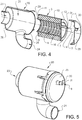
Fig. 4 is an exploded length-wise cross-section of the first embodiment of the filter element installed in the filter housing, -
Fig. 5 is a perspective view of the first embodiment of the filter element installed in the filter housing, -
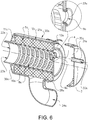
Fig. 6 , is a exploded, perspective length-wise cross-section of a second embodiment of a filter element installed in a second embodiment of a filter housing of this disclosure, -
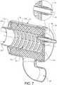
Fig. 7 is a perspective length-wise cross-section of the second embodiment of the filter element installed in the first embodiment of the filter housing of this disclosure, -
Fig. 8 is a schematical perspective view of a third embodiment of a filter element of this disclosure. - With reference to
Fig. 1 aheavy duty truck 1 is disclosed for which an internalcombustion engine system 2 of a kind disclosed in the present disclosure is advantageous. However, the internalcombustion engine system 2 may well be implemented also in other types of vehicles, such as in busses, in light-weight trucks, passenger cars, marine applications etc. The internalcombustion engine system 2 may be e.g. a diesel engine, which as such may be running on several different types of fuel, such as diesel or dimethyl ether, DME. Other fuel types are well suited, as well as hybrid systems. The internalcombustion engine system 2 is provided with anair filter element 5, ananchoring device 11 and anair filter housing 20 as disclosed herein. - An
air filter element 5 of the kind disclosed herein is located downstream anair intake 27 which draws air from the ambient. The ambient air is most often in need of filtration before being directed towards an inlet of the internalcombustion engine system 2. Downstream theair intake 26 anair pipe 27 directs the air to aninlet 24 of theair filter housing 20. Within theair filter housing 20 theair filter element 5 is located through which the air is filtered and further directed through anair outlet 23 and towards the internalcombustion engine system 2. Theair filter housing 20 is located in a lower region of thevehicle 1 and theair intake 27 in a higher region of thevehicle 1. In the depicted embodiment theair filter housing 20 is located directly behind a vehicle cab, whereas theair intake 26 is located on top of the vehicle cab at a rear end thereof. Theair pipe 27 is located at the rear end in a generally vertical position of the vehicle cab. Theair filter housing 20 is located having its axial direction transversal to the driving direction of thevehicle 1. The locations of the parts detailed above may well be otherwise. - Initially a description of a first embodiment of the present disclosure will be provided based on
Figs. 2a, 2b and2c .Reference numeral 5 refers to the whole design as shown inFig. 2a and is named filter element. Thefilter element 5 is adapted to be removably arranged in afilter housing 20 and comprises afilter material body 10 made of any material that is suited for the filtering operation of the fluid to be filtered. Thefilter housing 20 will be described in detail in relation toFig. 3 below. Thefilter element 5 is an air filter element and is adapted for cleaning air. Thefilter housing 20 is an air filter housing. - The
filter element 5 has an extension in a longitudinal direction along a longitudinal centre axis, and an extension in a transversal direction in a transversal plane which is perpendicular to the longitudinal direction and the longitudinal centre axis. Thefilter element 5 has a circular cylindrical tubular shape defining aninner space 8, wherein afirst outlet 22 and asecond outlet 9 is in communication with theinner space 8, as shown inFig. 2a . Thesecond outlet 9 has an offset position in relation to thefirst outlet 22 in the transversal direction of thefilter element 5. As can be gleaned fromFig. 2 , the offset position involves a distance, and preferably is a distance, in the transversal direction of thefilter element 5. The offset position is measured as a mutual distance as seen in the transversal direction of thefilter element 5 between a centre point in thefirst outlet 22 and a centre point in thesecond outlet 9. Thefirst outlet 22 is located coaxially with thefilter element 5, or in other words such that its centre point lies on the longitudinal centre axis of thefilter element 5. The offset position of thesecond outlet 9 in relation to thefirst outlet 22 is consequently in this embodiment measured as a distance in the transversal direction of thefilter element 5 between the longitudinal centre axis of thefilter element 5 and the centre point of thesecond outlet 9. Thefirst outlet 22 is adapted for conveying clean air to the internalcombustion engine system 2, and thesecond outlet 9 is adapted for conveying clean air to an auxiliary component which may be located within the internalcombustion engine system 2, or may be of other kind and position in thevehicle 1. In this embodiment, thefirst outlet 22 and thesecond outlet 9, respectively, have an axial extension. Consequently, thefirst outlet 22 has afirst centre axis 3 coinciding with the centre point of thefirst outlet 22, and thesecond outlet 9 has asecond centre axis 4 coinciding with the centre point of thesecond outlet 9, depicted inFig. 2a , wherein the offset position of thesecond outlet 9 in relation to thefirst outlet 22 is measured as an offset position between thesecond centre axis 4 in relation to thefirst centre axis 3 in the transversal direction of thefilter element 5. Thefirst centre axis 3 is coinciding with the longitudinal centre axis of thefilter element 5. - The
filter element 5 has afirst end 6 and asecond end 7. Thesecond end 7 is located opposite to thefirst end 6 in relation to thefilter element 5 along the longitudinal centre axis. Thefilter element 5 further has afirst end panel 11 at thefirst end 6 and asecond end panel 12 at thesecond end 7, wherein thefirst outlet 22 is located in thefirst end panel 11 and thesecond outlet 9 is located in thesecond end panel 12, as depicted inFig. 2a . Thefirst end panel 6 is arranged to block any filtered fluid to exit thefilter element 5 axially through thefirst end panel 11 other than through thefirst outlet 22. Thefirst end panel 6 is hence located at thefirst end 6 such that it covers both thefilter material body 10 and any parts of theinner space 8 surrounding thefirst outlet 22 at this end. Thesecond end panel 12 is arranged to block any filtered fluid to exit thefilter element 5 axially through thesecond end panel 12 other than through thesecond outlet 9. Thesecond end panel 12 is hence located at thesecond end 7 such that it covers both thefilter material body 10 and any parts of theinner space 8 surrounding thesecond outlet 9 at this end. Thefirst end panel 6 and thesecond end panel 12 may be made of a single panel as in the depicted embodiment, or of a combination of materials and/or sub-panels. Both thefirst end panel 6 and thesecond end panel 12 are made planar and parallel to the transversal direction of thefilter element 5. Further, both thefirst outlet 22 and thesecond outlet 9 have a cylindrical cross-section. Thefirst outlet 22 is located coaxially with thefilter element 5. -
Fig. 2b discloses that the cross-sectional area and the diameter of thesecond outlet 9 are substantially smaller than the cross-sectional area and the diameter of theinner space 8. It should be noted that the cross-sectional area and the diameter of thesecond outlet 9 is substantially smaller than the cross-sectional area and the diameter of thefirst outlet 22. - Disclosed in
Fig. 2c is the cross-sectional shape and diameter of thefirst outlet 22 which is substantially the same as the cross-sectional shape and diameter of theinner space 8. - Furthermore, the
filter element 5 comprises afilter material body 10 surrounding theinner space 8. When thefilter element 5 is used in connection with an internalcombustion engine system 2, i.e. when the filtering operation is performed on air such as ambient air, thefilter material body 10 is made of a material such as paper or cellulose. The paperfilter material body 10 of the depicted embodiments has a corrugated or pleated surface, but may also be made otherwise and of other suitable materials, or material combinations, - As illustrated in i.a.
Fig. 2a thefilter element 5 of this embodiment comprises aninner portion 16 for maintaining the shape of thefilter element 5 in use of thefilter element 5 when air is filtered through thefilter material body 10. When thefilter material body 10 is made of a relatively seen flexible material and design, it could otherwise collapse due to the air pressure during use. Theinner portion 16 is tubular and air permeable, and is made of a plastic material. Theinner portion 16 is in the present embodiment made as a rectangular net, but could also have any other shape which may maintain the shape of thefilter element 5, while not interfering the air flow through thefilter element 5. The material may also be of other kind. The thickness of theinner portion 16 is small in relation to the thickness of thefilter material body 10. - A sealing
portion 29 is arranged to thefilter element 5 for sealing engagement around thefirst outlet 22. The sealingportion 29 is made of a flexible rubber material which may adapt in use to a surface of the filter housing or of a pipe portion to which it abuts. - It may be gleaned from
Figs. 2a and 2b that thesecond end panel 12 comprises a protrudingpipe portion 31 which adjoins and surrounds thesecond outlet 9. The protrudingpipe portion 31 is made in one piece with thesecond end panel 12. The protrudingpipe portion 31 is designed for connection to an adjoining pipe for further distribution of filtered secondary air to an auxiliary component. - The reason for positioning the
second outlet 9 in the depicted position is to improve the acoustic response of thefilter element 5. Thefilter element 5 may consequently be used as a noise reduction means. The larger the offset between thefirst center axis 3 and thesecond axis 4 the better from a noise reduction point of view. The best noise reduction properties will be achieved when a maximum distance is used for the offset. In the depicted embodiment thesecond outlet 9 is hence positioned as close as possible to the inner side of thefilter material body 10, which position is related to the diameter of thesecond outlet 9. This position is achieved when the outer periphery of thesecond outlet 9 is located adjacent to the periphery of theinner space 8 and consequently of thefilter material body 10. In other words, the centre point of thesecond outlet 8 and thus thesecond centre axis 4 is located at a distance corresponding to half the diameter, i.e. to the radius, of thesecond outlet 9 from the periphery of theinner space 8. - Correspondingly, the outer periphery of the
first outlet 22 is located adjacent to the periphery of theinner space 8 in a position across thefilter element 5 as seen in relation to the position of thesecond outlet 9. Since the diameter of thefirst outlet 22 is substantially the same as the diameter of theinner space 8, thefirst outlet 22 cannot be positioned otherwise in this embodiment and hence a maximum offset position is achieved. If however the diameter of thefirst outlet 22 would be less than the diameter of theinner space 8, then it would be possible to further increase the offset position between thefirst outlet 22 and thesecond outlet 9. The maximum available offset position is set by the geometrical constraints of thefilter element 5, such that the maximum available offset position equals a distance or length corresponding to the diameter of theinner space 8 subtracted by the radius of the outer periphery of thesecond outlet 9 and by the radius of the outer periphery of thefirst outlet 22. The offset position should be at least 50 %, or preferably at least 75 %, or more preferably at least 90 % of the maximum available offset position. - Turning now to
Fig. 3 , a flow of air to be filtered through thefilter element 5 is disclosed in relation to thefilter housing 20. Thefilter housing 20 has an extension in a longitudinal direction along a longitudinal centre axis, and an extension in a transversal direction in a transversal plane which is perpendicular to the longitudinal direction and the longitudinal centre axis. Thefilter housing 20 comprises afluid inlet 24, a firstfluid outlet 23 and asecond fluid outlet 30. Thefluid inlet 24 is located in the curved outer periphery, or in other words, in the envelope surface of thefilter housing 20. The curved envelope surface is circular cylindrical. Thefluid inlet 24 is furthermore slightly inclined in relation to a normal to the outer periphery. Thefilter housing 20 has ahousing lid 35 for opening thefilter housing 20 to lay ainner housing space 21 bare which is adapted to receive thefilter element 5. Thehousing lid 35 is also adapted to seal the opening in thefilter housing 20 when thehousing lid 35 is closed. Thefilter housing 20 further has afirst end 36 and asecond end 28, at opposite ends of theinner housing space 21 along the longitudinal centre axis . Thehousing lid 35 is part of, or even encompasses, thesecond end 28 of thefilter housing 20. Both thefirst end 36 and thesecond end 28 of thefilter housing 20 are generally parallel to a transversal direction of thefilter housing 20. Thehousing lid 35 is closed using otherwise known clips. - The first
fluid outlet 23 is located in thefirst end 36 and thesecond fluid outlet 30 is located in thehousing lid 35. In correspondence with the design of thefilter element 5, the firstfluid outlet 23 is located coaxially with the envelope surface of thefilter housing 20. The firstfluid outlet 23 has a first centre axis and thesecond fluid outlet 30 has a second centre axis. Also in correspondence with the design of thefilter element 5, the offset position of thesecond fluid outlet 30 in relation to the firstfluid outlet 23 is defined by an offset position between the second centre axis in relation to the first centre axis in the transversal direction of thefilter housing 20. The offset position involves a distance, and preferably is a distance, in the transversal direction of thefilter housing 20. The offset position is measured as a mutual distance as seen in the transversal direction of thefilter housing 20 between a centre point in saidfirst outlet 23 to a centre point in saidsecond outlet 30. Thesecond fluid outlet 30 is furthermore located in a position the most far away from thefluid inlet 24 in thefilter housing 20 in order to improve the acoustic response of thefilter housing 20. In order for thefilter element 5 to be installable in thefilter housing 20, the firstfluid outlet 23 is positioned within thefilter housing 20 in a position corresponding to the position of thefirst outlet 22 in thefilter element 5, and thesecond fluid outlet 30 is positioned within thefilter housing 20 in a position corresponding to the position of thesecond outlet 9 in thefilter element 5. - The
housing lid 35 has at thesecond fluid outlet 30 apipe portion 30 which is made in one piece with thehousing lid 35. Thepipe portion 30 has an inner diameter which is adapted to tightly enclose the protrudingpipe portion 31 of thefilter element 5 when thefilter element 5 is installed in the filter housing 20.Thepipe portion 30 is shorter than the protrudingpipe portion 31, such that the protrudingpipe portion 31 in use protrudes past thepipe portion 30 for connection to an adjoining pipe. Thepipe portion 30 is thus adapted to also seal off theinner housing space 21 from the ambient. - When in use, the air to be filtered, represented by
arrow 100, hence enters thefilter housing 20 through thefluid inlet 24, spreads around the outside of thefilter element 5 within thefilter housing 20 and theinner housing space 21, penetrates through thefilter element 5 and thefilter material body 10, such that the air is filtered, and finally the filtered, and preferably generally cleaned air, leaves thefilter housing 20 through the firstfluid outlet 23 and thesecond fluid outlet 30. The air which leaves thefilter housing 20 through the firstfluid outlet 23 is represented byarrow 200, and the air which leaves through thesecond fluid outlet 30 is represented byarrow 300. Theair pipe 27 which connects to thefluid inlet 24 is inclined such that the fluid has a flow component directed slightly towards the firstfluid outlet 23. - It should be noted that the
filter housing 20 may have many other designs and still maintain the filtering, noise reduction and housing function in relation to thefilter element 5. - The
filter housing 20 has generally the same curved shape as thefilter element 5 in order to distribute the air well around thefilter element 5. An outer surface of thefilter element 5 is adapted to be closely aligned with a curved inner surface of thefilter housing 20, as depicted inFig. 4 , in which thefilter element 5 is disclosed in a position installed in thefilter housing 20. Thefilter housing 20 has a curved inner surface which is slightly larger than the outer curved shape of thefilter element 5, such that the air to be filtered may spread well around thefilter element 5 in order to utilise the full outer surface are of thefilter element 5. - In
Fig. 4 is may be gleaned that the protrudingpipe portion 31 of thefilter element 5 protrudes through thepipe portion 30 of thefilter housing 20. It may also be gleaned that the sealingportion 29 at thefirst outlet 22 of thefilter element 5 is adapted in size and position to the firstfluid outlet 23 of thefilter housing 20 in order to seal off theinner housing space 21 from the ambient and theinner space 8 from theinner housing space 21. - As depicted in
Fig.5 thefilter element 5 is disclosed installed in thefilter housing 20 with thehousing lid 35 closed. Generally only the protrudingpipe portion 31 may be seen of thefilter element 5. - According to a second embodiment depicted in
Fig. 6 thefilter housing 20a comprises ahousing lid 35a, wherein thehousing lid 35a encompasses thesecond outlet 9a. In this embodiment thelid 35a of thefilter housing 20a has apipe portion 30a which enters through thesecond outlet 9a of thefilter element 5a into theinner space 8a of thefilter element 5a. It also protrudes in an opposite direction, out of thefilter housing 20a for connection to an adjoining pipe for further distribution of filtered secondary air to an auxiliary component. Thepipe portion 30a according to this embodiment hence protrudes in both directions of thehousing lid 35a. Thesecond outlet 9a of thefilter element 5a represents a hole, without any protruding pipe portion as was the case for the first embodiment. Thesecond outlet 9 however has asealing 33a which encompasses the hole and which surrounds thepipe portion 30a when installed in thefilter housing 20a. Thesealing 33a is used in order to seal between theinner space 8a, theinner housing space 21 and the ambient. - According to a third embodiment depicted in
Fig. 7 , a filter system is disclosed which is a combination of the second embodiment of thefilter element 5a and the first embodiment of thefilter housing 20. Thehousing lid 35 comprises apipe portion 30 at thesecond outlet 30 for connection to an adjoiningpipe 34. The adjoiningpipe 34 is only shown in the part which closely encloses thepipe portion 30, and the adjoiningpipe 34 may either continue towards the auxiliary component, or may be used to, in turn, be connected to another pipe which continues towards the auxiliary component. The adjoiningpipe 34 is in this embodiment extending into thefilter housing 20a, and has an extension length which is adapted to arrange for a desired acoustic response in use of thefilter housing 20 and thefilter element 5a. The extension length should consequently be adapted to size, shape and other configuration of the filter system. - The
filter element Fig. 8 . In such a case thefilter element 5b has a first extension in a first direction and a second extension in a second direction which is perpendicular to the first direction. In order for the filter element to become elliptical or oval the first extension is greater than the second extension. In the depicted embodiment also thefirst outlet 22b and thesecond outlet 9b are also oval or elliptical. The offset position of thesecond outlet 9b in relation to thefirst outlet 22b is in such a case along the first extension direction. This way thesecond outlet 9b may be positioned at a maximum distance from the inlet into the filter housing, in order to improve the acoustic response of the filter system. In such a filter system the filter housing is equally either oval or elliptically shaped. It should be noted that neither thefirst outlet 22b nor thesecond outlet 9b must be oval or elliptical when thefilter element 5b is, but could for ease of connection to other components of the internal combustion engine system or other application be circular cylindrical. The maximum available offset position equals in this embodiment a distance or length corresponding to the extension in the first direction of theinner space 8 subtracted by half of the extension in the first direction of the outer periphery of thesecond outlet 9 and by half of the extension in the first direction of the outer periphery of thefirst outlet 22. The offset position should be at least 50 %, or preferably at least 75 %, or more preferably at least 90 % of the maximum available offset position. - In the above disclosed embodiments the direction of fluid flow may be opposite to the one depicted, the size of the
filter housing filter element filter material body filter element first outlet second outlet second outlet second outlets
Claims (15)
- An air filter element (5, 5a, 5b) having a tubular shape defining an inner space (8), said filter element (5, 5a, 5b) having a first end (6) and a second end (7) located opposite to said first end (6) in relation to a longitudinal direction of said filter element (5, 5a, 5b), a first outlet (22, 22a, 22b) located in said first end (6) and in communication with said inner space (8) and a second outlet (9, 9a, 9b) located in said second end (7) and in communication with said inner space (8), wherein the first outlet (22, 22a, 22b) has a first centre axis (3, 3b) and the second outlet (9, 9a, 9b) has a second centre axis (4, 4b), wherein said first centre axis (3a, 3b) and said second centre axis (4, 4b) are parallel to one another, wherein the first centre axis (3a, 3b) and said second centre axis (4, 4b) are arranged at an offset position in relation to one another in a direction perpendicular to the extension of the first and second centre axes, wherein a cross-sectional area of the second outlet (9, 9a, 9b) is smaller than a cross-sectional area of the first outlet (22, 22a, 22b).
- A filter element (5, 5a, 5b) according to claim 1, wherein said offset position involves a distance, and preferably is a distance, in the transversal direction of said filter element (5, 5a, 5b).
- A filter element (5, 5a, 5b) according to any one of the preceding claims, wherein said offset position is a distance as seen in the transversal direction of the filter element (5, 5a, 5b) between a centre point in said first outlet (22, 22a, 22b) and a centre point in said second outlet (9, 9a, 9b).
- A filter element (5, 5a, 5b) according to any one of the preceding claims, wherein said filter element (5, 5a, 5b) has a first end panel (11, 11a, 11b) at said first end (6) and a second end panel (12, 12a, 12b) at said second end (7), wherein said first outlet (22, 22a, 22b) is located in said first end panel (11, 11a, 11b).
- A filter element (5, 5a, 5b) according to any one of the preceding claims, wherein said second outlet (9, 9a, 9b) is located in said second end panel (12, 12a, 12b).
- A filter element (5, 5a, 5b)according to any one of the preceding claims, wherein said filter element (5b) has a cross-sectional shape with a first extension in a first direction and a second extension in a second direction which is perpendicular to said first direction.
- A filter element (5, 5a, 5b) according to claim 6, wherein said first extension is greater than the second extension such that said cross-sectional shape is oval, preferably generally elliptical.
- A filter element (5, 5a, 5b) according to claim 7, wherein said offset position of said second outlet (9b) in relation to said first outlet (22b) is along the first extension direction.
- A filter element (5, 5a, 5b) according to any one of the preceding claims, wherein said filter element (5b) has a maximum available offset position which equals to a length corresponding to an extension in said first direction of said inner space (8b) subtracted by half of an extension in said first direction of an outer periphery of said second outlet (9b) and by half of an extension in said first direction of an outer periphery of said first outlet (22b), wherein said offset position is at least 50 %, or preferably at least 75 %, or more preferably at least 90 % of said maximum available offset position.
- A filter element (5, 5a, 5b) according to any one of the preceding claims, wherein said first outlet (22, 22a) and/or said second outlet (9, 9a) has a cylindrical cross-section.
- A filter element (5, 5a, 5b)according to any one of the preceding claims, wherein said first outlet (22, 22a, 22b) is located coaxially with said filter element (5, 5a, 5b).
- A filter element (5, 5a, 5b) according to any one of the preceding claims, wherein a cross-sectional shape and dimension of said first outlet (22, 22a, 22b) is the same as a cross-sectional shape and dimension of the inner space (8).
- A filter element (5, 5a, 5b) according to any one of the preceding claims, wherein a cross-sectional area of the second outlet (9, 9a, 9b) is smaller than a cross-sectional area of the inner space (8).
- An internal combustion engine (2) comprising a filter element according to any one of claims 1 - 13.
- A vehicle (1) comprising an internal combustion engine (2) according to claim 14.
Priority Applications (1)
| Application Number | Priority Date | Filing Date | Title |
|---|---|---|---|
| EP20152363.6A EP3673970B1 (en) | 2015-12-18 | 2016-12-16 | Filter housing comprising two offset outlets in communication with filter inner space, as well as corresponding filter system |
Applications Claiming Priority (2)
| Application Number | Priority Date | Filing Date | Title |
|---|---|---|---|
| PCT/EP2015/080534 WO2017102027A1 (en) | 2015-12-18 | 2015-12-18 | Filter element comprising two offset outlets in communication with filter inner space, as well as corresponding housing |
| PCT/EP2016/081350 WO2017103048A1 (en) | 2015-12-18 | 2016-12-16 | Filter element comprising two offset outlets in communication with filter inner space, as well| as corresponding housing |
Related Child Applications (1)
| Application Number | Title | Priority Date | Filing Date |
|---|---|---|---|
| EP20152363.6A Division EP3673970B1 (en) | 2015-12-18 | 2016-12-16 | Filter housing comprising two offset outlets in communication with filter inner space, as well as corresponding filter system |
Publications (2)
| Publication Number | Publication Date |
|---|---|
| EP3389822A1 EP3389822A1 (en) | 2018-10-24 |
| EP3389822B1 true EP3389822B1 (en) | 2020-01-29 |
Family
ID=55071005
Family Applications (2)
| Application Number | Title | Priority Date | Filing Date |
|---|---|---|---|
| EP20152363.6A Active EP3673970B1 (en) | 2015-12-18 | 2016-12-16 | Filter housing comprising two offset outlets in communication with filter inner space, as well as corresponding filter system |
| EP16825353.2A Active EP3389822B1 (en) | 2015-12-18 | 2016-12-16 | Filter element comprising two offset outlets in communication with filter inner space, as well as corresponding housing |
Family Applications Before (1)
| Application Number | Title | Priority Date | Filing Date |
|---|---|---|---|
| EP20152363.6A Active EP3673970B1 (en) | 2015-12-18 | 2016-12-16 | Filter housing comprising two offset outlets in communication with filter inner space, as well as corresponding filter system |
Country Status (5)
| Country | Link |
|---|---|
| US (1) | US11090594B2 (en) |
| EP (2) | EP3673970B1 (en) |
| CN (1) | CN108472569B (en) |
| BR (1) | BR112018012220B1 (en) |
| WO (2) | WO2017102027A1 (en) |
Families Citing this family (17)
| Publication number | Priority date | Publication date | Assignee | Title |
|---|---|---|---|---|
| DE112020002029T5 (en) * | 2019-04-19 | 2022-01-05 | Donaldson Company, Inc. | FILTER ELEMENT WITH NON-RETURN VALVE AT THE OUTLET |
| DE102019131033A1 (en) * | 2019-11-18 | 2021-05-20 | Mann+Hummel Gmbh | Air filter with a primary air outlet and a secondary air outlet |
| DE102019131037A1 (en) * | 2019-11-18 | 2021-05-20 | Mann+Hummel Gmbh | Air filter with a primary air outlet and a secondary air outlet and filter element therefor |
| WO2021154490A1 (en) * | 2020-01-31 | 2021-08-05 | Cummins Filtration Inc. | Compact air cleaner assembly wth noise reduction device |
| DE102020103065A1 (en) | 2020-02-06 | 2021-08-12 | Mann+Hummel Gmbh | Air filter with a primary air outlet and a secondary air outlet and filter element therefor |
| DE102020103039A1 (en) | 2020-02-06 | 2021-08-12 | Mann+Hummel Gmbh | Air filter with a primary air outlet and a secondary air outlet and filter element therefor |
| DE102021101274A1 (en) | 2020-02-06 | 2021-08-12 | Mann+Hummel Gmbh | Air filter with a primary air outlet and a secondary air outlet and filter element therefor |
| DE102020103044A1 (en) | 2020-02-06 | 2021-08-12 | Mann+Hummel Gmbh | Filter element for an air filter with a primary air outlet and a secondary air outlet and air filter and assembly method |
| CN115087492A (en) * | 2020-02-21 | 2022-09-20 | 沃尔沃卡车集团 | Air filter element |
| WO2021164885A1 (en) * | 2020-02-21 | 2021-08-26 | Volvo Truck Corporation | An air filter hosuing and an air filter element |
| DE102020116398B4 (en) | 2020-06-22 | 2025-09-04 | Mann+Hummel Gmbh | Filter element, housing for a filter system and filter system with a filter element and a housing |
| US12415151B2 (en) | 2020-07-03 | 2025-09-16 | Volvo Truck Corporation | Filter housing and an air filter system |
| DE102020122027B4 (en) | 2020-08-24 | 2023-05-04 | Mann+Hummel Gmbh | Silencer and filter system |
| DE102020122024A1 (en) | 2020-08-24 | 2022-02-24 | Mann+Hummel Gmbh | Filter element and filter system |
| DE102021112125A1 (en) * | 2021-05-10 | 2022-11-10 | Mann+Hummel Gmbh | Filter system with a resonator |
| EP4092293B1 (en) * | 2021-05-21 | 2024-08-21 | Volvo Car Corporation | Transmission gear assembly with a breather cavity |
| CN118437092A (en) * | 2023-02-06 | 2024-08-06 | 开利公司 | Air filter assembly |
Family Cites Families (19)
| Publication number | Priority date | Publication date | Assignee | Title |
|---|---|---|---|---|
| US4964984A (en) * | 1989-06-14 | 1990-10-23 | Electromedics, Inc. | Blood filter |
| US5190651A (en) | 1991-06-24 | 1993-03-02 | Sta-Rite Industries, Inc. | Filter cartridge |
| US6537339B2 (en) * | 2001-05-04 | 2003-03-25 | Nelson Industries, Inc. | Moisture draining inside-out reverse flow air filter, mold and method |
| DE10159097A1 (en) | 2001-12-01 | 2003-06-12 | Mahle Filtersysteme Gmbh | Intake air filter for an internal combustion engine |
| US6875259B2 (en) * | 2002-02-26 | 2005-04-05 | Siemens Vdo Automotive, Inc. | Low cost combined air cleaner and resonator assembly |
| CN100507257C (en) * | 2003-09-18 | 2009-07-01 | A.凯塞汽车系统有限公司 | Valve and filter device for fuel supply system |
| GB2450735B (en) | 2007-07-05 | 2012-11-28 | Air Safety Ltd | Air filter assembly |
| DE202008014211U1 (en) * | 2008-10-24 | 2010-03-11 | Mann+Hummel Gmbh | Air filter for the air supplied to an internal combustion engine in a motor vehicle |
| US20110024344A1 (en) * | 2009-08-03 | 2011-02-03 | Cummins Filtration Ip, Inc. | No filter no run fluid filtration system |
| DE102010009268A1 (en) * | 2010-02-25 | 2011-08-25 | MAHLE International GmbH, 70376 | Filter element and filter device |
| DE102010009249A1 (en) * | 2010-02-25 | 2011-08-25 | MAHLE International GmbH, 70376 | filtering device |
| DE102011077712A1 (en) | 2011-06-17 | 2012-12-20 | Mahle International Gmbh | filter element |
| WO2013063497A2 (en) * | 2011-10-26 | 2013-05-02 | Donaldson Company, Inc | Filter assemblies; components and features thereof: and, methods of use and assembly |
| SE536415C2 (en) | 2012-03-01 | 2013-10-15 | Scania Cv Ab | Filter housing and filter unit |
| DE102012112653A1 (en) * | 2012-12-19 | 2014-06-26 | Dr. Ing. H.C. F. Porsche Aktiengesellschaft | Air filter for internal combustion engine in motor vehicle, has filter insert that is designed with cylindrical-shaped or oval-shaped filter element, such that filter element is fixedly connected with two clean-air ports |
| DE102014000927A1 (en) | 2013-02-12 | 2014-08-14 | Mann + Hummel Gmbh | filter element |
| CN105228717B (en) | 2013-03-22 | 2017-02-01 | 卡特彼勒公司 | filter components |
| DE102014006850B4 (en) | 2013-06-20 | 2022-08-25 | Mann+Hummel Gmbh | Filter housing, hollow filter element and filter |
| CN105745005B (en) * | 2013-11-19 | 2018-07-24 | 曼·胡默尔有限公司 | Filter core for filter device |
-
2015
- 2015-12-18 WO PCT/EP2015/080534 patent/WO2017102027A1/en not_active Ceased
-
2016
- 2016-12-16 EP EP20152363.6A patent/EP3673970B1/en active Active
- 2016-12-16 US US16/063,174 patent/US11090594B2/en active Active
- 2016-12-16 WO PCT/EP2016/081350 patent/WO2017103048A1/en not_active Ceased
- 2016-12-16 EP EP16825353.2A patent/EP3389822B1/en active Active
- 2016-12-16 BR BR112018012220-3A patent/BR112018012220B1/en active IP Right Grant
- 2016-12-16 CN CN201680074028.7A patent/CN108472569B/en active Active
Also Published As
| Publication number | Publication date |
|---|---|
| BR112018012220A2 (en) | 2018-11-27 |
| US20180369732A1 (en) | 2018-12-27 |
| WO2017103048A1 (en) | 2017-06-22 |
| CN108472569B (en) | 2021-09-28 |
| EP3673970A1 (en) | 2020-07-01 |
| EP3673970C0 (en) | 2025-03-12 |
| CN108472569A (en) | 2018-08-31 |
| US11090594B2 (en) | 2021-08-17 |
| WO2017102027A1 (en) | 2017-06-22 |
| EP3389822A1 (en) | 2018-10-24 |
| EP3673970B1 (en) | 2025-03-12 |
| BR112018012220B1 (en) | 2022-05-17 |
Similar Documents
| Publication | Publication Date | Title |
|---|---|---|
| EP3673970B1 (en) | Filter housing comprising two offset outlets in communication with filter inner space, as well as corresponding filter system | |
| US9314725B2 (en) | Filter element | |
| US20170296957A9 (en) | Housing, Housing Cover and Connecting Part of a Device for Separating at Least One Fluid From a Gas and a Device for the Separation of a Fluid | |
| US7765990B2 (en) | Device for delivering fuel from a tank to an internal combustion engine | |
| US10391436B2 (en) | Housing, housing cover and connecting part of a device for separating at least one fluid from a gas and a device for the separation of a fluid | |
| CN108367221B (en) | Filter element with flat shape adapted to be locked into curved shape | |
| EP4106902B1 (en) | An air filter element | |
| US9206774B2 (en) | Cowl-mounted air cleaner | |
| US12629624B2 (en) | Air filter element | |
| EP2902613A1 (en) | Air noise reduction device | |
| US7758677B2 (en) | Filtering device | |
| EP4106901B1 (en) | An air filter hosuing and an air filter element | |
| US12415151B2 (en) | Filter housing and an air filter system | |
| WO2015102822A1 (en) | Filter element having dual filtration capacity and filter assembly | |
| EP3911430B1 (en) | Air filter housing arrangement |
Legal Events
| Date | Code | Title | Description |
|---|---|---|---|
| STAA | Information on the status of an ep patent application or granted ep patent |
Free format text: STATUS: UNKNOWN |
|
| STAA | Information on the status of an ep patent application or granted ep patent |
Free format text: STATUS: THE INTERNATIONAL PUBLICATION HAS BEEN MADE |
|
| PUAI | Public reference made under article 153(3) epc to a published international application that has entered the european phase |
Free format text: ORIGINAL CODE: 0009012 |
|
| STAA | Information on the status of an ep patent application or granted ep patent |
Free format text: STATUS: REQUEST FOR EXAMINATION WAS MADE |
|
| 17P | Request for examination filed |
Effective date: 20180615 |
|
| AK | Designated contracting states |
Kind code of ref document: A1 Designated state(s): AL AT BE BG CH CY CZ DE DK EE ES FI FR GB GR HR HU IE IS IT LI LT LU LV MC MK MT NL NO PL PT RO RS SE SI SK SM TR |
|
| AX | Request for extension of the european patent |
Extension state: BA ME |
|
| DAV | Request for validation of the european patent (deleted) | ||
| DAX | Request for extension of the european patent (deleted) | ||
| GRAP | Despatch of communication of intention to grant a patent |
Free format text: ORIGINAL CODE: EPIDOSNIGR1 |
|
| STAA | Information on the status of an ep patent application or granted ep patent |
Free format text: STATUS: GRANT OF PATENT IS INTENDED |
|
| INTG | Intention to grant announced |
Effective date: 20190828 |
|
| GRAS | Grant fee paid |
Free format text: ORIGINAL CODE: EPIDOSNIGR3 |
|
| GRAA | (expected) grant |
Free format text: ORIGINAL CODE: 0009210 |
|
| STAA | Information on the status of an ep patent application or granted ep patent |
Free format text: STATUS: THE PATENT HAS BEEN GRANTED |
|
| AK | Designated contracting states |
Kind code of ref document: B1 Designated state(s): AL AT BE BG CH CY CZ DE DK EE ES FI FR GB GR HR HU IE IS IT LI LT LU LV MC MK MT NL NO PL PT RO RS SE SI SK SM TR |
|
| REG | Reference to a national code |
Ref country code: GB Ref legal event code: FG4D |
|
| REG | Reference to a national code |
Ref country code: CH Ref legal event code: EP |
|
| REG | Reference to a national code |
Ref country code: AT Ref legal event code: REF Ref document number: 1228082 Country of ref document: AT Kind code of ref document: T Effective date: 20200215 |
|
| REG | Reference to a national code |
Ref country code: IE Ref legal event code: FG4D |
|
| REG | Reference to a national code |
Ref country code: DE Ref legal event code: R096 Ref document number: 602016028922 Country of ref document: DE |
|
| REG | Reference to a national code |
Ref country code: SE Ref legal event code: TRGR |
|
| REG | Reference to a national code |
Ref country code: NL Ref legal event code: MP Effective date: 20200129 |
|
| PG25 | Lapsed in a contracting state [announced via postgrant information from national office to epo] |
Ref country code: RS Free format text: LAPSE BECAUSE OF FAILURE TO SUBMIT A TRANSLATION OF THE DESCRIPTION OR TO PAY THE FEE WITHIN THE PRESCRIBED TIME-LIMIT Effective date: 20200129 Ref country code: NO Free format text: LAPSE BECAUSE OF FAILURE TO SUBMIT A TRANSLATION OF THE DESCRIPTION OR TO PAY THE FEE WITHIN THE PRESCRIBED TIME-LIMIT Effective date: 20200429 Ref country code: FI Free format text: LAPSE BECAUSE OF FAILURE TO SUBMIT A TRANSLATION OF THE DESCRIPTION OR TO PAY THE FEE WITHIN THE PRESCRIBED TIME-LIMIT Effective date: 20200129 Ref country code: PT Free format text: LAPSE BECAUSE OF FAILURE TO SUBMIT A TRANSLATION OF THE DESCRIPTION OR TO PAY THE FEE WITHIN THE PRESCRIBED TIME-LIMIT Effective date: 20200621 |
|
| REG | Reference to a national code |
Ref country code: LT Ref legal event code: MG4D |
|
| PG25 | Lapsed in a contracting state [announced via postgrant information from national office to epo] |
Ref country code: GR Free format text: LAPSE BECAUSE OF FAILURE TO SUBMIT A TRANSLATION OF THE DESCRIPTION OR TO PAY THE FEE WITHIN THE PRESCRIBED TIME-LIMIT Effective date: 20200430 Ref country code: LV Free format text: LAPSE BECAUSE OF FAILURE TO SUBMIT A TRANSLATION OF THE DESCRIPTION OR TO PAY THE FEE WITHIN THE PRESCRIBED TIME-LIMIT Effective date: 20200129 Ref country code: IS Free format text: LAPSE BECAUSE OF FAILURE TO SUBMIT A TRANSLATION OF THE DESCRIPTION OR TO PAY THE FEE WITHIN THE PRESCRIBED TIME-LIMIT Effective date: 20200529 Ref country code: HR Free format text: LAPSE BECAUSE OF FAILURE TO SUBMIT A TRANSLATION OF THE DESCRIPTION OR TO PAY THE FEE WITHIN THE PRESCRIBED TIME-LIMIT Effective date: 20200129 Ref country code: BG Free format text: LAPSE BECAUSE OF FAILURE TO SUBMIT A TRANSLATION OF THE DESCRIPTION OR TO PAY THE FEE WITHIN THE PRESCRIBED TIME-LIMIT Effective date: 20200429 |
|
| PG25 | Lapsed in a contracting state [announced via postgrant information from national office to epo] |
Ref country code: NL Free format text: LAPSE BECAUSE OF FAILURE TO SUBMIT A TRANSLATION OF THE DESCRIPTION OR TO PAY THE FEE WITHIN THE PRESCRIBED TIME-LIMIT Effective date: 20200129 |
|
| PG25 | Lapsed in a contracting state [announced via postgrant information from national office to epo] |
Ref country code: SM Free format text: LAPSE BECAUSE OF FAILURE TO SUBMIT A TRANSLATION OF THE DESCRIPTION OR TO PAY THE FEE WITHIN THE PRESCRIBED TIME-LIMIT Effective date: 20200129 Ref country code: DK Free format text: LAPSE BECAUSE OF FAILURE TO SUBMIT A TRANSLATION OF THE DESCRIPTION OR TO PAY THE FEE WITHIN THE PRESCRIBED TIME-LIMIT Effective date: 20200129 Ref country code: EE Free format text: LAPSE BECAUSE OF FAILURE TO SUBMIT A TRANSLATION OF THE DESCRIPTION OR TO PAY THE FEE WITHIN THE PRESCRIBED TIME-LIMIT Effective date: 20200129 Ref country code: RO Free format text: LAPSE BECAUSE OF FAILURE TO SUBMIT A TRANSLATION OF THE DESCRIPTION OR TO PAY THE FEE WITHIN THE PRESCRIBED TIME-LIMIT Effective date: 20200129 Ref country code: CZ Free format text: LAPSE BECAUSE OF FAILURE TO SUBMIT A TRANSLATION OF THE DESCRIPTION OR TO PAY THE FEE WITHIN THE PRESCRIBED TIME-LIMIT Effective date: 20200129 Ref country code: SK Free format text: LAPSE BECAUSE OF FAILURE TO SUBMIT A TRANSLATION OF THE DESCRIPTION OR TO PAY THE FEE WITHIN THE PRESCRIBED TIME-LIMIT Effective date: 20200129 Ref country code: LT Free format text: LAPSE BECAUSE OF FAILURE TO SUBMIT A TRANSLATION OF THE DESCRIPTION OR TO PAY THE FEE WITHIN THE PRESCRIBED TIME-LIMIT Effective date: 20200129 Ref country code: ES Free format text: LAPSE BECAUSE OF FAILURE TO SUBMIT A TRANSLATION OF THE DESCRIPTION OR TO PAY THE FEE WITHIN THE PRESCRIBED TIME-LIMIT Effective date: 20200129 |
|
| REG | Reference to a national code |
Ref country code: DE Ref legal event code: R097 Ref document number: 602016028922 Country of ref document: DE |
|
| REG | Reference to a national code |
Ref country code: AT Ref legal event code: MK05 Ref document number: 1228082 Country of ref document: AT Kind code of ref document: T Effective date: 20200129 |
|
| PLBE | No opposition filed within time limit |
Free format text: ORIGINAL CODE: 0009261 |
|
| STAA | Information on the status of an ep patent application or granted ep patent |
Free format text: STATUS: NO OPPOSITION FILED WITHIN TIME LIMIT |
|
| 26N | No opposition filed |
Effective date: 20201030 |
|
| PG25 | Lapsed in a contracting state [announced via postgrant information from national office to epo] |
Ref country code: IT Free format text: LAPSE BECAUSE OF FAILURE TO SUBMIT A TRANSLATION OF THE DESCRIPTION OR TO PAY THE FEE WITHIN THE PRESCRIBED TIME-LIMIT Effective date: 20200129 Ref country code: AT Free format text: LAPSE BECAUSE OF FAILURE TO SUBMIT A TRANSLATION OF THE DESCRIPTION OR TO PAY THE FEE WITHIN THE PRESCRIBED TIME-LIMIT Effective date: 20200129 |
|
| PG25 | Lapsed in a contracting state [announced via postgrant information from national office to epo] |
Ref country code: SI Free format text: LAPSE BECAUSE OF FAILURE TO SUBMIT A TRANSLATION OF THE DESCRIPTION OR TO PAY THE FEE WITHIN THE PRESCRIBED TIME-LIMIT Effective date: 20200129 Ref country code: PL Free format text: LAPSE BECAUSE OF FAILURE TO SUBMIT A TRANSLATION OF THE DESCRIPTION OR TO PAY THE FEE WITHIN THE PRESCRIBED TIME-LIMIT Effective date: 20200129 |
|
| REG | Reference to a national code |
Ref country code: CH Ref legal event code: PL |
|
| GBPC | Gb: european patent ceased through non-payment of renewal fee |
Effective date: 20201216 |
|
| PG25 | Lapsed in a contracting state [announced via postgrant information from national office to epo] |
Ref country code: MC Free format text: LAPSE BECAUSE OF FAILURE TO SUBMIT A TRANSLATION OF THE DESCRIPTION OR TO PAY THE FEE WITHIN THE PRESCRIBED TIME-LIMIT Effective date: 20200129 |
|
| REG | Reference to a national code |
Ref country code: BE Ref legal event code: MM Effective date: 20201231 |
|
| PG25 | Lapsed in a contracting state [announced via postgrant information from national office to epo] |
Ref country code: LU Free format text: LAPSE BECAUSE OF NON-PAYMENT OF DUE FEES Effective date: 20201216 Ref country code: IE Free format text: LAPSE BECAUSE OF NON-PAYMENT OF DUE FEES Effective date: 20201216 |
|
| PG25 | Lapsed in a contracting state [announced via postgrant information from national office to epo] |
Ref country code: CH Free format text: LAPSE BECAUSE OF NON-PAYMENT OF DUE FEES Effective date: 20201231 Ref country code: LI Free format text: LAPSE BECAUSE OF NON-PAYMENT OF DUE FEES Effective date: 20201231 Ref country code: GB Free format text: LAPSE BECAUSE OF NON-PAYMENT OF DUE FEES Effective date: 20201216 |
|
| PG25 | Lapsed in a contracting state [announced via postgrant information from national office to epo] |
Ref country code: TR Free format text: LAPSE BECAUSE OF FAILURE TO SUBMIT A TRANSLATION OF THE DESCRIPTION OR TO PAY THE FEE WITHIN THE PRESCRIBED TIME-LIMIT Effective date: 20200129 Ref country code: MT Free format text: LAPSE BECAUSE OF FAILURE TO SUBMIT A TRANSLATION OF THE DESCRIPTION OR TO PAY THE FEE WITHIN THE PRESCRIBED TIME-LIMIT Effective date: 20200129 Ref country code: CY Free format text: LAPSE BECAUSE OF FAILURE TO SUBMIT A TRANSLATION OF THE DESCRIPTION OR TO PAY THE FEE WITHIN THE PRESCRIBED TIME-LIMIT Effective date: 20200129 |
|
| PG25 | Lapsed in a contracting state [announced via postgrant information from national office to epo] |
Ref country code: MK Free format text: LAPSE BECAUSE OF FAILURE TO SUBMIT A TRANSLATION OF THE DESCRIPTION OR TO PAY THE FEE WITHIN THE PRESCRIBED TIME-LIMIT Effective date: 20200129 Ref country code: AL Free format text: LAPSE BECAUSE OF FAILURE TO SUBMIT A TRANSLATION OF THE DESCRIPTION OR TO PAY THE FEE WITHIN THE PRESCRIBED TIME-LIMIT Effective date: 20200129 |
|
| PG25 | Lapsed in a contracting state [announced via postgrant information from national office to epo] |
Ref country code: BE Free format text: LAPSE BECAUSE OF NON-PAYMENT OF DUE FEES Effective date: 20201231 |
|
| PGFP | Annual fee paid to national office [announced via postgrant information from national office to epo] |
Ref country code: FR Payment date: 20251223 Year of fee payment: 10 |
|
| PGFP | Annual fee paid to national office [announced via postgrant information from national office to epo] |
Ref country code: SE Payment date: 20251222 Year of fee payment: 10 |
|
| PGFP | Annual fee paid to national office [announced via postgrant information from national office to epo] |
Ref country code: DE Payment date: 20251229 Year of fee payment: 10 |