EP3389487B1 - Verfahren und messsystem zur datenerfassung und -verarbeitung in soft-tomografiestudien - Google Patents
Verfahren und messsystem zur datenerfassung und -verarbeitung in soft-tomografiestudien Download PDFInfo
- Publication number
- EP3389487B1 EP3389487B1 EP16869383.6A EP16869383A EP3389487B1 EP 3389487 B1 EP3389487 B1 EP 3389487B1 EP 16869383 A EP16869383 A EP 16869383A EP 3389487 B1 EP3389487 B1 EP 3389487B1
- Authority
- EP
- European Patent Office
- Prior art keywords
- measuring
- excitation
- unit
- units
- measurement
- Prior art date
- Legal status (The legal status is an assumption and is not a legal conclusion. Google has not performed a legal analysis and makes no representation as to the accuracy of the status listed.)
- Active
Links
Images

Classifications
-
- A—HUMAN NECESSITIES
- A61—MEDICAL OR VETERINARY SCIENCE; HYGIENE
- A61B—DIAGNOSIS; SURGERY; IDENTIFICATION
- A61B5/00—Measuring for diagnostic purposes; Identification of persons
- A61B5/05—Detecting, measuring or recording for diagnosis by means of electric currents or magnetic fields; Measuring using microwaves or radio waves
- A61B5/053—Measuring electrical impedance or conductance of a portion of the body
- A61B5/0536—Impedance imaging, e.g. by tomography
-
- G—PHYSICS
- G01—MEASURING; TESTING
- G01N—INVESTIGATING OR ANALYSING MATERIALS BY DETERMINING THEIR CHEMICAL OR PHYSICAL PROPERTIES
- G01N27/00—Investigating or analysing materials by the use of electric, electrochemical, or magnetic means
- G01N27/02—Investigating or analysing materials by the use of electric, electrochemical, or magnetic means by investigating impedance
-
- G—PHYSICS
- G06—COMPUTING OR CALCULATING; COUNTING
- G06T—IMAGE DATA PROCESSING OR GENERATION, IN GENERAL
- G06T12/00—Tomographic reconstruction from projections
- G06T12/20—Inverse problem, i.e. transformations from projection space into object space
-
- G—PHYSICS
- G01—MEASURING; TESTING
- G01N—INVESTIGATING OR ANALYSING MATERIALS BY DETERMINING THEIR CHEMICAL OR PHYSICAL PROPERTIES
- G01N21/00—Investigating or analysing materials by the use of optical means, i.e. using sub-millimetre waves, infrared, visible or ultraviolet light
- G01N21/01—Arrangements or apparatus for facilitating the optical investigation
- G01N21/03—Cuvette constructions
-
- G—PHYSICS
- G01—MEASURING; TESTING
- G01N—INVESTIGATING OR ANALYSING MATERIALS BY DETERMINING THEIR CHEMICAL OR PHYSICAL PROPERTIES
- G01N27/00—Investigating or analysing materials by the use of electric, electrochemical, or magnetic means
- G01N27/72—Investigating or analysing materials by the use of electric, electrochemical, or magnetic means by investigating magnetic variables
-
- G—PHYSICS
- G01—MEASURING; TESTING
- G01R—MEASURING ELECTRIC VARIABLES; MEASURING MAGNETIC VARIABLES
- G01R27/00—Arrangements for measuring resistance, reactance, impedance, or electric characteristics derived therefrom
- G01R27/02—Measuring real or complex resistance, reactance, impedance, or other two-pole characteristics derived therefrom, e.g. time constant
- G01R27/04—Measuring real or complex resistance, reactance, impedance, or other two-pole characteristics derived therefrom, e.g. time constant in circuits having distributed constants, e.g. having very long conductors or involving high frequencies
-
- G—PHYSICS
- G01—MEASURING; TESTING
- G01R—MEASURING ELECTRIC VARIABLES; MEASURING MAGNETIC VARIABLES
- G01R27/00—Arrangements for measuring resistance, reactance, impedance, or electric characteristics derived therefrom
- G01R27/02—Measuring real or complex resistance, reactance, impedance, or other two-pole characteristics derived therefrom, e.g. time constant
- G01R27/14—Measuring resistance by measuring current or voltage obtained from a reference source
-
- G—PHYSICS
- G06—COMPUTING OR CALCULATING; COUNTING
- G06T—IMAGE DATA PROCESSING OR GENERATION, IN GENERAL
- G06T12/00—Tomographic reconstruction from projections
- G06T12/10—Image preprocessing, e.g. calibration, positioning of sources or scatter correction
-
- G—PHYSICS
- G06—COMPUTING OR CALCULATING; COUNTING
- G06T—IMAGE DATA PROCESSING OR GENERATION, IN GENERAL
- G06T2207/00—Indexing scheme for image analysis or image enhancement
- G06T2207/10—Image acquisition modality
- G06T2207/10072—Tomographic images
Definitions
- the present invention relates to the completion of nondestructive soft-field tomography analysis of an object under study.
- the object of the present invention is a data acquisition and processing method, as well as a measuring system for the soft-field tomographic mapping of the internal structure of objects under study, specifically objects with inhomogeneous material distribution.
- the present invention particularly, provides a data acquisition/processing method, as well as a measuring system serving as a basis for a soft-field tomography analysis and/or an imaging method.
- the method and measuring system according to the invention may be used advantageously in industrial tomography processes, for nondestructive structural analysis of different materials (e.g. live wood), and in medical diagnostic methods (such as e.g.
- object may substantially refer to any material under study ranging from industrial articles through structures found in nature to organs/tissues forming parts of a human or animal body.
- tomographic sectional images This means that a planar section of the three dimensional object is studied by capturing one dimensional images in different directions along the plane and then attempting the reconstruction of the planar structure from said images.
- structure refers to the spatial variation/distribution of the absorption of the radiation applied - thus, tomography refers to the solution of this two-dimensional problem.
- X-ray radiation or acoustic radiation e.g. ultrasound is commonly used as the transilluminating radiation.
- Such a soft-field tomography method is, without completeness, amongst others the electrical resistance tomography (ERT), electrical capacitance tomography (ECT), electrical impedance tomography (EIT) and acoustic impedance tomography (AIT), which inspection methods are directed to the mapping and measuring of the spatial variance of the internal properties of the object under study, such as the electrical/dielectric or mechanical properties, e.g. the electrical conductance or electric permittivity or density, of the material defining the internal structure of the object, specifically, by means of performing e.g. magnetic or electrical impedance/admittance or acoustic impedance measurements.
- ERT electrical resistance tomography
- ECT electrical capacitance tomography
- EIT electrical impedance tomography
- AIT acoustic impedance tomography
- the object under study is subjected to excitation through one or more points thereof, and then the response of the material of the object to the excitation is measured at one or more points of the object.
- the excitation and/or the response measurement can be performed at one or more frequencies and/or instants of time.
- the image of the object studied is created subsequently by an image reconstruction method on the basis of the thus obtained measurement data.
- the source of the measurement errors may be e.g. the measuring system used for the excitation and/or data acquisition, the individual excitation- and/or measuring units used in the measuring system, i.e. their systematic errors, or the errors arising from the geometric positions occupied by the excitation and/or measuring units during the measurement.
- said systematic error is considered particularly important, because it cannot be measured by a preliminary calibration of the measuring system used for the analysis as due to the nonlinearity present in the system of the object and the measuring system, the object under study also influences the measuring system, and thus one or more parts thereof.
- U.S. Publication Pamphlet No. 2010/0127705 A1 discloses a method and system for carrying out tomographic analysis based on magnetic induction.
- the object under study is subjected to an alternating magnetic field generated by excitation coils arranged around the object, then alternating current signals carrying information characteristic to the electrical conductance of the object and the spatial distribution of said conductance is captured by suitable receiving units arranged in positions surrounding the object.
- Data acquisition is carried out at least at two different frequencies.
- a correction factor is derived through complicated mathematical algorithms, which may then be used for compensating the errors (scattered signals) arising due to a change in geometric positions of the excitation coils and/or receiving units.
- a drawback of the method is that only the imaginary part of the recorded data is used to derive the correction factor, which causes data loss. Furthermore, the method is also unable to manage systematic errors of the apparatus, the parts thereof, in particular, the excitation coils and/or receiving units.
- U.S. Publication Pamphlet No. 2013/0013239 A1 discusses the use of phase modulated or phase- and amplitude modulated excitation generally in soft-field tomographic methods to enhance the resolution of data acquisition/imaging.
- U.S. Patent No. US-8,593,154 B2 discloses a method and apparatus to suppress artifacts arising in soft-field tomography investigation.
- the used data acquisition system 20 is shown in Figure 1 .
- the electrical properties of the material of the object 22 under study, in particular, its electrical conductivity and the spatial distribution of the electrical conductivity are analyzed by EIT method.
- a plurality of transducers are arranged on or near a surface of the object 22. The transducers are used firstly to excite the material of the object 22 in the desired manner (here, electrically) and secondly to capture the response of the material of the object to this excitation and convert it to electrical signals.
- the transducers are electrically connected firstly to the excitation units 26 providing their drive and secondly to the response detectors 28 for capturing signals representing the response.
- the signals of the response detectors 28 are passed on to a soft-field tomography module 30 connected to the response detectors 28, whose task is to calculate/evaluate the response of the object 22 to the excitation, and optionally solving the so-called inverse problem connecting the response, the excitation and the electrical conductivity-distribution in the object.
- the correct operation of the data acquisition system 20 is provided by the control unit 33, which is connected to the excitation units 26 and to the module 30.
- the object is subjected to excitation by the transducers 24 according to an excitation pattern comprising a plurality of frequency- and/or time component, then one or more artifacts of the imaging, particularly errors resulting from the geometric arrangement of the transducers and the inability of the electrodes used therein to be fitted to the forward predictive model used in the module 30 are desired to be eliminated by separating the response according to components.
- the excitation and data acquisition schemes described in detail however do not alleviate the systematic errors caused by the data acquisition system 20 and the subassemblies thereof, moreover these are not even mentioned.
- the continuous (inhomogeneous, non-isotropic) medium (optionally comprising structural defects/deformations) is simplified to an impedance (or complex conductivity) network so that it may be managed with the toolset of numerical mathematics.
- Differential potentials are measured at the voltage electrodes with respect to an electrode (called as the voltage reference electrode) adjacent to the current-injecting electrode.
- the authors also discuss the so-called 'neighbouring method' for EIT data collection taking place on the boundary of said phantom, and the processing of the measurement data obtained in the various measurement geometries. Said publication keeps silent on how to suppress measurement errors, in particular, the common measurement errors that are inherent to the measurements performed on the phantoms or on any other object with the system of electrodes.
- the authors also discuss solutions: the frequent application of calibrations (which can be a rather complicated and laborious task, especially when plenty of electrodes are used) and the usage of various hardware elements wherein, in particular, the output impedance of a current generator applied for the excitations and the input impedances of the measurement elements are discrete resistances of a certain size.
- the object of the present invention is to provide a data acquisition/processing method and measuring system primarily for soft-field tomographic material analysis/imaging method, which is suitable for taking into account the systematic and common phase errors of the units used to carry out the soft-field tomography methods, in particular, the excitation units and also suppressing thereof in the recorded measurement data.
- the accuracy of data serving as the basis of the imaging is improved, which allows more accurate imaging of the of the internal structure of the object under study.
- a further object of the present invention is providing a data acquisition/processing method and measuring system primarily for soft-field tomography material analysis/imaging method, which is more reliable than other similar methods used nowadays regarding the solution of the equation system obtained in the linear network model approximation, i.e. regarding the determination of the unknown impedance values corresponding to the material properties of the analyzed object, i.e. actually regarding the solution of the inverse problem.
- the more reliable solution of the inverse problem also facilitates the improvement of the accuracy and resolution of the soft-field tomography imaging.
- a further object of the invention is to generally improve soft-field tomography imaging methods by providing a data acquisition/processing method and measuring system, which provides an improved data acquisition protocol to derive the equation system required for the solution of the inverse problem.
- the measurable phase shift occurring on the reference element is the result of the common measurement error, thus its extent may be simply determined by a phase shift measurement carried out on the reference element, and the measurement data can be compensated with its known value.
- the data acquisition is preferably carried out so as to ensure that the number of equations required to determine the impedance/admittance values belonging to the branches of the corresponding directed network graph at a certain level of discretization of the material of the object studied, i.e. at a given resolution of the data acquisition, surely exceed the number of unknowns in said equations.
- the data acquisition is preferably carried out so as to ensure that the derived equation system for solving the inverse problem is overdetermined.
- the object of the invention related to the aspect of a measuring system for data acquisition in a soft-field tomography investigation of an object under nondestructive study is achieved by elaborating the measuring system according to claim 1.
- Preferred exemplary embodiments of the measuring system according to the invention are set forth in claims 2 to 11.
- the object related to the aspect of a data acquisition and processing method to be used in soft-field tomography study of an object is achieved by the method according to claim 12.
- Further preferred exemplary implementations of the method according to the invention are set forth in claims 13 to 16.
- the data acquisition/processing method and system according to the invention to be used in connection with soft-field tomographic analysis/imaging methods is described in detail in the following in relation with such an embodiment thereof, which is related to the EIT method. Accordingly the data acquisition/processing method and system is described in connection with electric excitation and measurement of response thereto. Accordingly the object to be subjected to soft-field tomography analysis is subjected to electric excitation in this embodiment of the invention and the response obtained as a result of the electric excitation is considered the basis (input) of the solution of the system of equations established in the linear network model approximation (directed graph).
- the object under study is modeled with an impedance network, so the mathematical representation of the model is a directed (weighted) graph.
- the structure of the graph representing the object under study follows the same principles at any resolution of the soft-field tomography data acquisition.
- the geometric parameters unequivocally characterizing the graph i.e. the linear network), i.e. the number of nodes (n), branches (br) and closed loops (1) of the graph can be calculated by the following expressions
- the position coordinates of the nodes of the graph are chosen according to the optimal solution of the actual analysis task.
- the impedance (or admittance) values representing each branch have to be calculated for the soft-field tomographic characterization (imaging).
- the nodes on the extremities (outer perimeter) of the graph represent the measuring elements.
- the physical basis of this is that the field properties are to be determined by measurement or e.g. calculated in these points.
- the graph obtained according to the aforementioned may be described for quantitative characterization in matrix representation, generally by a so-called node-branch matrix (a size of which is br ⁇ n ) and a so-called loop-branch matrix (a size of which is br ⁇ l ) , which matrices comprise elements with values of -1, 0 or 1 depending on the relative positions of nodes, branches and loops.
- the solution of the inverse problem i.e. the image reconstruction requires the solution of a nonlinear system of equations.
- the measurement data acquired by the measuring elements on the perimeter of the graph i.e. the measured data of the response of the object to the excitation
- the system of equations concerning the network corresponding to the graph.
- a basic requisite of the solvability of the system of equations is that it should not be underdetermined. Keeping that in sight, the data acquisition scheme to be described in detail in the following is selected so that the system of equations is overdetermined for the conductivity and capacity values on each branch of the graph.
- the system of equations can be made overdetermined by the number of generator positions.
- el number of measuring elements in the case of EIT measurement, preferably metal electrodes
- el 2 which is equal to the maximal number of measurements.
- each possible combination has an equation system corresponding thereto.
- the unknown variable of each acquired equation system is the same impedance matrix. Accordingly the data acquisition scheme results in an overdetermined equation system.
- the object is subjected to excitation at a certain frequency through the measuring elements. If the grounded connector, from now on the ground point or cold spot (0 V; GND) of the signal generator carrying out the excitation is connected to one of the measuring elements, the other connector, representing - from now on - the alive point or hot spot (+I; GEN) of the signal generator, can be connected to any one of the remaining n -1 measuring elements. After completion, a measurement is carried out by the measuring circuits at this temporally fixed connector position of the signal generator, then the hot spot +I of the signal generator can be relocated to another measuring element.
- n -1 possibilities become available for relocating said hot spot +I of the signal generator; that is, by exploiting the reconnection possibilities discussed here, a maximum of el 2 measurements can be performed.
- one connector of the measuring unit of each measuring circuit is connected to the measuring element, and the other connector of the measuring units is connected to the cold spot GND of the signal generator. This way the potential of each measuring element is measured by the measuring units of the measuring circuits during the data acquisition.
- An advantage of the method is that the connectors of the measuring units connected to a common ground do not need to be lead out of the measuring element, thus only the remaining points are lead out. This reduces the frequency-dependent error caused by scattered capacitances and the measurement is simplified. If necessary, differences of each point may be generated digitally.
- the scheme of the data acquisition used by us comprises the following main steps:
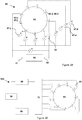
- the transmitting units 63-i are connected to the connectors of the signal generator 80 by suitable conduits, preferably through a multiplexer 70.
- the signal generator 80 is connected to a control device 90; in response to a suitable control signal of the control device 90, the signal generator emits an excitation signal having a predetermined signal shape, which is introduced into the object 62 by any two (i.e. one pair) of the transmitting units 63-i selected by the multiplexer 70 (according to Figure 3B in this example, by the transmitting units marked no. 2 and 6). Thus an excitation field is generated in the object 62.
- the introduction is particularly carried out so that the hot spot 81 of the generator 80 is connected to one of the selected transmitting units (in the example according to Figure 3B to the transmitting unit no. 6), while the cold spot 82 (i.e. grounding) of the signal generator 80 is connected to the other one of the selected transmitting units (in the example according to Figure 3B to the transmitting unit no. 2).
- the receiving units 65-j are arranged so that they have a common ground that is the same as the cold spot 82 of the signal generator 80.
- the receiving units 65-j form measuring circuits/measuring channels having common grounds in substantially arbitrary pairing through the multiplexer 70.
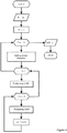
- the actual pairing to be used in a given measurement is provided/carried out by the multiplexer 70 according to a fix algorithm (see e.g. Figure 4 ).
- At least one measuring unit 67-1, 67-2, ..., 67-el corresponds to each thus obtained measuring circuit.
- the receiving units 65-j detect the response (qualitative characterization) in different geometric positions on the object 62 given to the excitation field generated in the material of the object 62 by the transmitting units 63-i, while the measuring units 67-j provide the expression of the response with numerical values (measurement data) i.e. the quantitative characterization.
- the measurement data obtained in the actual measuring configuration are transferred through the multiplexer 70 to the measuring data acquisition unit 85, which is connected to the control unit 90 in a suitable manner.
- a reference element 64 (preferably being well measurable with known parameters, thus with a given ohmic resistance) is inserted between the cold spot 82 of the signal generator 80 and one of the receiving units of one of the measuring circuits used for data acquisition in the actual measuring configuration into this measuring circuit.
- the data acquisition method independent of the geometric position of the connectors of the signal generator 80 (i.e. of the hot 81 and cold 82 spots) measurement is carried out simultaneously/at the same time on each receiving unit 65-j relative to the cold spot 82 of the signal generator 80.
- the positions of the differential measuring inputs of the measuring circuits are not changed during the data acquisition at any given measurement configuration, only the connectors of the signal generator 80 are placed - independently of each other - to different geometric positions on the object 62 by the multiplexer 70 preferably during a systematical scanning.
- the grounds of the signal generator 80 and the receiving units 65-j are common.
- the excitation and the data acquisition (measurement) are carried out relative to the common point.
- the common point in said method does not correspond to 0 V, but to a value offset from that by a constant.
- the offset is caused by the reference element 64 (preferably a purely ohmic resistor) with known resistance inserted on the cold spot 82 side of the signal generator 80.
- the common measurement errors (effectively the systematic error of the signal generator 80, common phase errors etc.) occurring when measuring the object 62 under study also occur on the reference element 64.
- the potential values measured on the object 62 by the measuring units 67-j in each measuring circuit can be simply compensated, i.e. the measurement data that could be obtained by a measurements relative to 0 V can be simply generated therefrom e.g. by subtraction.
- the systematic errors are greatly reduced during processing of the measurement data (e.g. by subtraction, ratio calculation), i.e. by carrying out the data acquisition with the inserted reference element 64, the measurement data can be practically made independent of the common measurement errors of the data acquisition system 60 that were thought to be impossible to be eliminated in the past.
- a further advantage of the method is that it also reduces statistical errors.
- soft-field tomography imaging methods require measurement data relative to 0 V
- secondly soft-field tomography imaging methods are exceptionally sensitive for uncompensated errors occurring in the measurement system and during measuring processes, therefore improvement of the quality of the imaging requisites the reduction of errors.
- the transmitting units 63-i and/or the receiving units 65-j may be arranged directly on the surface of the object 62 under study, e.g. in the form of metal electrodes. It is hereby noted, that the transmitting units 63-i and/or the receiving units 65-j may also be arranged inside (i.e. penetrating into) the object 62 for excitation and/or for data acquisition. E.g. needle electrodes may serve as an example of such an arrangement.
- a transmitting unit 63-i and a receiving unit 65-j may also be formed as a single integrated measuring sensor, or with other words as a transducer, which significantly simplifies the creation of the measuring system.
- excitation may be generated in the material forming the object 62 by the transmitting units 63-i based on the type thereof, among others e.g. electric, magnetic, optical or thermal excitation.
- the coupling of the transmitting units 63-i, the receiving units 65-j, or transducers, and the object 62 may be of different nature, e.g. electric, capacitive, galvanic, heat-exchanging and so on.
- the excitation waveform is generally a (pure) sinusoidal/cosinusoidal waveform, but the excitation itself may be carried out by a bipolar square signal provided by the signal generator 80. Moreover, the signal generator 80 may also be operated in current generator or voltage generator operation mode.
- the measuring system 100 suitable for soft-field tomography data acquisition illustrated schematically in Figure 3B comprises the data acquisition system 60, the signal generator 80 and measuring data acquisition unit 85 connected thereto through the multiplexer 70, and the control unit 90 for controlling the signal generator 80 and the measuring data acquisition unit 85 and optionally for carrying out the (pre)processing of the measured data, together with any necessary accessories - known to a person skilled in the art - e.g. suitable signal amplifiers, signal conditioning units, optionally with further noise-filters and other similar devices (e.g. power supply, conduits etc.) necessary for the operation of the measuring system 100.
- any necessary accessories - known to a person skilled in the art - e.g. suitable signal amplifiers, signal conditioning units, optionally with further noise-filters and other similar devices (e.g. power supply, conduits etc.) necessary for the operation of the measuring system 100.
- the multiplexer 70 is a suitably programmable unit to provide excitation in different, systematically selected and scanned transmitting unit positions.
- the measuring data acquisition unit 85 itself is also configured as a programmable unit.
- the control device 90 may be provided in the form of a personal computer (PC) or a programmable microcontroller. Implementing the control device 90 as a personal computer is particularly preferable, if soft-field tomography imaging is also to be carried out based on the measured data.
- the measuring units 67-j may also be provided in the form of ordinary voltmeters, however in cases where the number of measuring units 67-j is relatively high, they are preferably provided in the form of high-resolution precision measuring devices (e.g. lock-in amplifiers). It is particularly preferable to use devices based on the lock-in principle in cases where the data acquisition is carried out at e.g. a plurality of frequencies.
- Said raw measurement data are subjected to preprocessing before being used in soft-field tomography imaging, preferably by the control device itself; however the preprocessing may also be carried out by a dedicated processing unit.
- the goal of the preprocessing is the linearization of the data to be imported into the soft-field tomography imaging algorithm e.g. for the (in this case impedance-based) reconstruction of the internal structure of the object under study, and to detach said measurement data from the data acquisition system used to acquire said data, and from common measurement errors.
- the data vectors acquired in the i -th measuring configuration according to the example and also compensated regarding the systematic error caused by the data acquisition system are obtained in the form: Z I 3 , A 2 3 ,0 , A 4 3 , A 5 3 , A 6 3 , A 7 3 , A 8 3 T and ⁇ Z 3 , ⁇ ⁇ 2 3 ,0 , ⁇ ⁇ 4 3 , ⁇ ⁇ 5 3 , ⁇ ⁇ 6 3 , ⁇ ⁇ 7 3 , ⁇ ⁇ 8 3 T .
- the raw measurement data are converted into the form of attenuation- and phase data, each as an n ⁇ i sized matrix that can be used in the image reconstruction of soft-field tomography analysis methods, particularly of an EIT method by the transformations carried out according to the above steps of (1) to (6).
- the impedance (or admittance) values on each branch are frequency-dependent. This means, that the measurement results of measurements carried out at different frequencies are different, but the parameters (resistance, capacity etc.) used for their processing are the same in every equation system. This provides opportunity to double the number of equations by repeating the data acquisition scheme described above at a different frequency. Therefore it is not necessary to run the data acquisition for el 2 number of possibilities, as the number of equation systems may be multiplied by carrying out the excitation at a second, third, etc. frequency. As a result, the equation system to be solved can be made overdetermined for graphs of any complexity. Accordingly, when the soft-field tomography analysis is planned, the goal is to find frequencies preferably optimal for the measurement.
- the raw measurement data obtained at different frequencies are stored in two n ⁇ i sized matrices per frequencies during the aforementioned preprocessing.
- the object of the invention is a data acquisition/processing method and measuring system for mapping the selected properties of an object under study, to be used as part of a soft-field tomographic (nondestructive) material testing method (imaging).
- imaging a soft-field tomographic (nondestructive) material testing method
- the parameters of an electric field generated in the material of the object are determined, preferably at least at one frequency, by measuring units preferably arranged on the surface of the object under study and connected to the same potential as the signal generator, preferably on its cold side which is on ground potential.
- the internal (i.e. volumetric) structure of the analyzed object may be determined by establishing and solving the equation system according to the linear network model approximation corresponding to the measurement data.
- the systematic error caused by the entire data acquisition system and the common phase error of the data acquisition system can be determined, and the obtained raw measurement data may be compensated for this so-called common measurement errors.
- the object under study is preferably modeled by an (electric) impedance network characterized by a directed network graph for carrying out the calculations.
- multiple types of data acquisition may be carried out together/in combination by suitable selection of the transmitting units/receiving units for each data acquisition positions. This also increases the resolution of the soft-field tomography analysis method, and significantly increases the information content of the measurement data.
- the linear network associated with the object under study can be transformed into a more simple geometric form by e.g. Mobius transformation, thus the analysis of the created potential field becomes more simple.
- Mobius transformation discretization of the material of the object under study follows the electric field created therein more closely, thus the impedance values obtained by the solution of the inverse problem characterize the internal structure of the object under study more accurately, which results in the improvement of the soft-field tomography imaging/analysis.
Landscapes
- Health & Medical Sciences (AREA)
- Physics & Mathematics (AREA)
- Life Sciences & Earth Sciences (AREA)
- General Physics & Mathematics (AREA)
- Pathology (AREA)
- General Health & Medical Sciences (AREA)
- Chemical & Material Sciences (AREA)
- Engineering & Computer Science (AREA)
- Nuclear Medicine, Radiotherapy & Molecular Imaging (AREA)
- Immunology (AREA)
- Analytical Chemistry (AREA)
- Biochemistry (AREA)
- Theoretical Computer Science (AREA)
- Biophysics (AREA)
- Heart & Thoracic Surgery (AREA)
- Animal Behavior & Ethology (AREA)
- Biomedical Technology (AREA)
- Public Health (AREA)
- Veterinary Medicine (AREA)
- Radiology & Medical Imaging (AREA)
- Surgery (AREA)
- Medical Informatics (AREA)
- Molecular Biology (AREA)
- Electrochemistry (AREA)
- Chemical Kinetics & Catalysis (AREA)
- Investigating Or Analyzing Materials By The Use Of Electric Means (AREA)
- Measurement And Recording Of Electrical Phenomena And Electrical Characteristics Of The Living Body (AREA)
- Algebra (AREA)
- Mathematical Analysis (AREA)
- Mathematical Optimization (AREA)
- Mathematical Physics (AREA)
- Pure & Applied Mathematics (AREA)
- Analysing Materials By The Use Of Radiation (AREA)
- Measurement Of Resistance Or Impedance (AREA)
Claims (16)
- Messsystem (100) zur Datenerfassung in der Weichfeldtomografieanalyse eines Objekts (62), wobei das Messsystem (100) Übertragungseinheiten (63-i), Empfangseinheiten (65-j), Messeinheiten (67-j), eine Anregungseinheit mit einem heißen Fleck (81) und einem kalten Fleck (82), eine Messdatenerfassungseinheit (85) und eine Steuerungseinheit (90) umfasst, wobei im Betriebszustand des Messsystems (100) die Steuerungseinheit (90) betriebsbereit mit der Anregungseinheit und der Messdatenerfassungseinheit (85) verbunden ist, um die Anregungseinheit und die Messdatenerfassungseinheit (85) zu steuern;
die Anregungseinheit gleichzeitig durch ihren heißen Fleck (81) und ihren kalten Fleck (82) mit jeweils einer Übertragungseinheit (63-i) verbunden ist, um die Übertragungseinheiten (63-i) anzutreiben, wobei der kalte Fleck (82) der Anregungseinheit der Betriebserde entspricht;
mindestens die mit der Anregungseinheit verbundenen Übertragungseinheiten (63-i) nacheinander mit dem zu untersuchenden Objekt (62) gekoppelt sind, um ein Anregungsfeld innerhalb des Objekts (62) zu erzeugen;
die Empfangseinheiten (65-j) nacheinander mit dem zu untersuchenden Objekt (62) gekoppelt sind, um eine Reaktion auf das Anregungsfeld innerhalb des Objekts (62) zu detektieren, wobei
die Empfangseinheiten (65-j) paarweise miteinander verbunden sind, um Messkreise zu bilden, um die von den Empfangseinheiten (65-j) anhand von Messdaten quantitativ detektierte Reaktion zu charakterisieren, wobei jeder der Messkreise eine Messeinheit (67-j) mit mindestens einem ersten und einem zweiten Messeingang für die quantitative Charakterisierung umfasst, wobei die erste und zweite Empfangseinheit der Messkreise mit dem ersten bzw. zweiten Messeingang der Messeinheit (67-j) in dem Messkreis verbunden sind und die Betriebserde jeder der Empfangseinheiten (65-j) mit dem kalten Fleck der Anregungseinheit verbunden ist; und
die Messeinheiten (67-j) jedes Messkreises mit der Messdatenerfassungseinheit (85) verbunden sind, um die Messdaten zu erfassen;
dadurch gekennzeichnet, dass
ein Referenzelement (64) in einen der Messkreise zwischen dem kalten Fleck (82) der Anregungseinheit und einer der mit dem kalten Fleck (82) verbundenen Empfangseinheiten (65-j) eingesetzt ist, um die jeweiligen Messdaten, die von der jeweiligen mit dem kalten Fleck (82) verbundenen Empfangseinheit (65-j) bereitgestellt werden, um einen Offset-Wert zu verschieben. - Messsystem (100) nach Anspruch 1, dadurch gekennzeichnet, dass es weiter einen Multiplexer (70) umfasst, wobei der Multiplexer (70) zwischen der Anregungseinheit und den von der Anregungseinheit angetriebenen Übertragungseinheiten (63-i) sowie jeder der Empfangseinheit (65-j) und der Messdatenerfassungseinheit (85) eingesetzt ist, wobei der Multiplexer (70) konfiguriert ist, um die mit der Anregungseinheit verbundenen Übertragungseinheiten (63-i) mit den jeden Messkreis bildenden Empfangseinheiten (65-j) betriebsbereit zu beliebigen Paaren zu verbinden.
- Messsystem (100) nach Anspruch 1 oder 2, dadurch gekennzeichnet, dass das Referenzelement (64) durch ein Element bekannter Parameter bereitgestellt wird, bevorzugt ein Element mit einem rein ohmschen Widerstand eines bestimmten Werts, und der Offset-Wert ein konstanter Wert ist.
- Messsystem (100) nach einem der Ansprüche 1 bis 3, dadurch gekennzeichnet, dass die Messeingänge der Messeinheiten (67-j) unterschiedliche Messeingänge sind.
- Messsystem (100) nach einem der Ansprüche 1 bis 4, dadurch gekennzeichnet, dass die Messeinheiten (67-j) durch Präzisionsmessgeräte mit hoher Auflösung, vorzugsweise durch Lock-in-Verstärker, bereitgestellt werden.
- Messsystem (100) nach einem der Ansprüche 1 bis 5, dadurch gekennzeichnet, dass die Anregungseinheit durch einen Signalgenerator (80) bereitgestellt wird, der im Betriebszustand entweder als Stromgenerator oder als Spannungsgenerator fungieren kann.
- Messsystem (100) nach einem der Ansprüche 1 bis 6, dadurch gekennzeichnet, dass die Übertragungseinheiten (63-i) durch Geräte bereitgestellt werden, die zur elektrischen Anregung des zu untersuchenden Objekts (62) konfiguriert sind, und die Messeinheiten (67-j) durch Voltmeter bereitgestellt werden.
- Messsystem (100) nach einem der Ansprüche 1 bis 7, dadurch gekennzeichnet, dass die Übertragungseinheiten (63-i) und die Empfangseinheiten (65-j) als Geräte konfiguriert sind, die geeignet sind, um entweder auf einer Oberfläche angeordnet zu sein oder mindestens teilweise innerhalb des Volumens des zu untersuchenden Objekts (62) eingerichtet zu sein.
- Messsystem (100) nach einem der Ansprüche 1 bis 8, dadurch gekennzeichnet, dass die Übertragungseinheiten (63-i) und die Empfangseinheiten (65-j) aus einer Gruppe ausgewählt sind, die aus Metallelektroden und Nadelelektroden besteht.
- Messsystem (100) nach einem der Ansprüche 1 bis 9, dadurch gekennzeichnet, dass die Kopplung zwischen jeder der Übertragungseinheiten (63-i) und/oder Empfangseinheiten (65-j) und dem zu untersuchenden Objekt (62) ausgewählt ist aus der Gruppe, bestehend aus elektrischer, kapazitiver, galvanischer, Wärmetausch- und optischer Kopplung.
- Messsystem (100) nach einem der Ansprüche 1 bis 10, dadurch gekennzeichnet, dass die Übertragungseinheiten (63-i) und die Empfangseinheiten (65-j) durch Messdetektoren bereitgestellt werden, die einstückig die Funktionen sowohl der Übertragungs- als auch der Empfangseinheiten umfassen.
- Verfahren zur Datenerfassung in der Weichfeldtomografieanalyse eines Objekts (62), wobei das Verfahren die folgenden Schritte umfasst(i) Verkoppeln der Übertragungseinheiten (63-i) und Empfangseinheiten (65-j) mit dem Objekt (62) in Anordnungen mit bestimmten geometrischen Mustern;(ii) Unterziehen des Objekts (62) einer volumetrischen Anregung durch das mindestens eine Paar Übertragungseinheiten (63-i) mittels Antreiben des Paares Übertragungseinheiten durch ein von der Anregungseinheit generiertes Anregungssignal, Verbinden einer Übertragungseinheit der das/die Paar(e) bildenden Übertragungseinheiten (63-i) mit dem heißen Fleck (81) der Anregungseinheit und Verbinden der anderen Übertragungseinheit mit dem kalten Fleck (82) der Anregungseinheit, wobei der kalte Fleck (82) der Anregungseinheit der Betriebserde entspricht;(iii) Erzeugen von Messdaten durch Messen der vollständigen Reaktion des Objekts (62) auf die Anregung durch die Messkreise, erzeugt aus durch Empfangseinheiten (65-j) gebildete Empfangseinheitspaare, wobei jeder Messkreis weiter mindestens eine Messeinheit (67-j) umfasst, wobei die Messeinheit (67-j) einen ersten und einen zweiten Messeingang aufweist, wobei - beim Ausführen der Messung - eine Empfangseinheit (65-j) jedes mit dem Objekt (62) gekoppelten Empfangseinheitspaares mit dem ersten Messeingang und dem zweiten Messeingang verbunden ist;(iv) Speichern der erhaltenen Messdaten;(v) Wiederholen der Schritte (ii)-(iv) nach dem Substituieren mindestens einer der die Anregung durchführenden Übertragungseinheiten (63-i) mit einer anderen Übertragungseinheit von den mit dem Objekt (62) gekoppelten Übertragungseinheiten und/oder nach dem Substituieren mindestens einer Empfangseinheit (65-j) des mindestens einen der die Messung durchführenden Messkreise mit einer anderen Empfangseinheit von den mit dem Objekt (62) gekoppelten Empfangseinheiten;wobei das Verfahren weiter die folgenden Schritte umfasst- Verbinden der Betriebserde jeder Empfangseinheit (65-j) mit dem kalten Fleck der Anregungseinheit, dadurch Anregen des Objekts (62), und Durchführen jeder Messung während des Verbundenseins mit einem gemeinsamen Potential, gekennzeichnet durch- Einsetzen eines Referenzelements (64) in einen der Messkreise zwischen dem kalten Fleck (82) der Anregungseinheit und einer der mit dem kalten Fleck (82) verbundenen Empfangseinheiten (65-j) und Durchführen einer Messung an dem Referenzelement (64) gleichzeitig mit der Messung der vollständigen Reaktion des Objekts (62) auf die Anregung und dadurch Erhalten von Messdaten zu der jeweiligen mit dem kalten Fleck (82) verbundenen Empfangseinheit (65-j), verschoben um einen Offset-Wert, der für systematische und gemeinsame Phasenfehler repräsentativ ist, wobei das Ergebnis der an dem Referenzelement (64) durchgeführten Messung ebenfalls gespeichert wird.
- Verfahren nach Anspruch 12, wobei die Substitution einer der Übertragungseinheiten (63-i) und/oder die Substitution mindestens einer der Empfangseinheiten (65-j) mindestens eines der Messkreise in einer von einem Multiplexer (70) gesteuerten Weise durchgeführt wird, wobei die Übertragungseinheiten (63-i) und/oder die Empfangseinheiten (65-j) gescannt werden.
- Verfahren nach Anspruch 12 oder 13, wobei das Objekt (62) diskretisiert und durch einen gerichteten Graphen, der vor Einleitung der Messung in einer Netzmodellnäherung erhalten wurde, repräsentiert wird und die Wiederholung der Schritte (ii)-(iv) fortgesetzt wird, bis eine Überdeterminierung eines Gleichungssystems zum Determinieren der von den Verzweigungen des gerichteten Graphen repräsentierten Impedanzwerte erreicht ist, wobei die Unbekannten der Gleichungen, die das Gleichungssystem bilden, Impedanzwerte sind und Koeffizienten davon die Messdaten sind, die durch Messen der Gesamtreaktion des Objekts (62) auf die Anregung erhalten werden.
- Verfahren nach einem der Ansprüche 12 bis 14, wobei die Anregung des Objekts (62) bei unterschiedlichen Anregungsfrequenzen oder durch Auslagern des heißen Flecks (81) und des kalten Flecks (82) der Anregungseinheit auf die Übertragungseinheiten (63-i) durchgeführt wird, um die Überdeterminierung des Gleichungssystems zu erreichen.
- Verfahren nach einem der Ansprüche 12 bis 15, wobei das Referenzelement (64) ein rein ohmscher Widerstand ist und die durch Messen der vollständigen Reaktion des Objekts (62) auf die Anregung erhaltenen Messdaten in Messdaten umgewandelt werden, bei denen die systematischen und gemeinsamen Phasenfehler des zur Datenerfassung verwendeten Messsystems nach einem der Ansprüche 1 bis 11 durch Nutzung der Messdaten, die um einen mittels Durchführen der Messung an dem Referenzelement (64) erhaltenen Offset-Wert verschoben wurden, ausgeglichen wurden.
Applications Claiming Priority (2)
| Application Number | Priority Date | Filing Date | Title |
|---|---|---|---|
| HU1500616A HUP1500616A2 (en) | 2015-12-14 | 2015-12-14 | Data collecting and processing method and arrangement for soft-tomographic examinations |
| PCT/HU2016/050062 WO2017125770A1 (en) | 2015-12-14 | 2016-12-14 | Process and measuring system for data acquisition and processing in soft-tomography studies |
Publications (2)
| Publication Number | Publication Date |
|---|---|
| EP3389487A1 EP3389487A1 (de) | 2018-10-24 |
| EP3389487B1 true EP3389487B1 (de) | 2020-06-17 |
Family
ID=89992023
Family Applications (1)
| Application Number | Title | Priority Date | Filing Date |
|---|---|---|---|
| EP16869383.6A Active EP3389487B1 (de) | 2015-12-14 | 2016-12-14 | Verfahren und messsystem zur datenerfassung und -verarbeitung in soft-tomografiestudien |
Country Status (6)
| Country | Link |
|---|---|
| US (1) | US10699446B2 (de) |
| EP (1) | EP3389487B1 (de) |
| JP (1) | JP6791966B2 (de) |
| CA (1) | CA3007977A1 (de) |
| HU (2) | HUP1500616A2 (de) |
| WO (1) | WO2017125770A1 (de) |
Families Citing this family (6)
| Publication number | Priority date | Publication date | Assignee | Title |
|---|---|---|---|---|
| HUP1500616A2 (en) | 2015-12-14 | 2017-07-28 | Pecsi Tudomanyegyetem | Data collecting and processing method and arrangement for soft-tomographic examinations |
| EP3646017A1 (de) * | 2017-06-30 | 2020-05-06 | 3M Innovative Properties Company | Verifizierung der strukturellen integrität von materialien mithilfe elektrischer eigenschaften |
| DE102019209199A1 (de) * | 2019-06-26 | 2020-12-31 | Technische Universität Hamburg | Messinstrument für Eigenschaften eines strömenden Mediums |
| CN114384122A (zh) * | 2022-01-07 | 2022-04-22 | 湘潭大学 | 一种基于电阻抗成像的含水木材缺陷检测方法 |
| US12050191B2 (en) * | 2022-11-16 | 2024-07-30 | Khalifa University of Science and Technology | Method for accelerating the data acquisition throughput of electrical tomography systems |
| CN119896469B (zh) * | 2025-04-01 | 2025-07-04 | 浙江大学 | 个体头部组织电导率模型构建方法及系统 |
Family Cites Families (20)
| Publication number | Priority date | Publication date | Assignee | Title |
|---|---|---|---|---|
| GB9226376D0 (en) * | 1992-12-18 | 1993-02-10 | British Tech Group | Tomography |
| DE10156833A1 (de) * | 2001-11-20 | 2003-05-28 | Boehm Stephan | Elektrode für biomedizinische Messungen |
| JP4409331B2 (ja) * | 2004-03-30 | 2010-02-03 | 株式会社トプコン | 光画像計測装置 |
| US7660617B2 (en) * | 2004-11-13 | 2010-02-09 | The Boeing Company | Electrical impedance tomography using a virtual short measurement technique |
| US7545979B2 (en) * | 2005-04-12 | 2009-06-09 | General Electric Company | Method and system for automatically segmenting organs from three dimensional computed tomography images |
| DE102005031751B4 (de) * | 2005-07-07 | 2017-09-14 | Drägerwerk AG & Co. KGaA | Elektroimpedanztomographie-Gerät mit Gleichtaktsignalunterdrückung |
| AT504060B1 (de) | 2006-07-24 | 2010-03-15 | Univ Graz Tech | Vorrichtung zur magnetischen induktionstomografie |
| US8115934B2 (en) * | 2008-01-18 | 2012-02-14 | The Board Of Trustees Of The University Of Illinois | Device and method for imaging the ear using optical coherence tomography |
| US8378682B2 (en) * | 2009-11-17 | 2013-02-19 | Muralidhara Subbarao | Field image tomography for magnetic resonance imaging |
| US8264246B2 (en) | 2010-01-05 | 2012-09-11 | General Electric Company | Electrical network representation of a distributed system |
| US8593154B2 (en) * | 2010-12-24 | 2013-11-26 | General Electric Company | System and method for artifact suppression in soft-field tomography |
| JP5820750B2 (ja) * | 2011-03-14 | 2015-11-24 | 株式会社Ihi | トモグラフィ装置及びトモグラフィ計測方法 |
| US8508240B2 (en) * | 2011-03-23 | 2013-08-13 | General Electric Company | System and method for soft-field tomography data acquisition |
| US8892379B2 (en) * | 2011-06-30 | 2014-11-18 | General Electric Company | System and method for soft-field reconstruction |
| US20130013239A1 (en) * | 2011-07-08 | 2013-01-10 | General Electric Company | System and method for excitation generation in soft-field tomography |
| JP2013073734A (ja) * | 2011-09-27 | 2013-04-22 | Toshiba Lighting & Technology Corp | 照明装置 |
| US9445741B2 (en) * | 2011-10-31 | 2016-09-20 | General Electric Company | System and method for beamforming in soft-field tomography |
| US8983578B2 (en) * | 2012-02-27 | 2015-03-17 | General Electric Company | System and method for transducer placement in soft-field tomography |
| HUP1500616A2 (en) | 2015-12-14 | 2017-07-28 | Pecsi Tudomanyegyetem | Data collecting and processing method and arrangement for soft-tomographic examinations |
| WO2017103180A1 (en) | 2015-12-18 | 2017-06-22 | F. Hoffmann-La Roche Ag | Automated clinical diagnostic system and method |
-
2015
- 2015-12-14 HU HU1500616A patent/HUP1500616A2/hu unknown
-
2016
- 2016-12-14 US US16/062,319 patent/US10699446B2/en active Active
- 2016-12-14 JP JP2018531076A patent/JP6791966B2/ja active Active
- 2016-12-14 WO PCT/HU2016/050062 patent/WO2017125770A1/en not_active Ceased
- 2016-12-14 CA CA3007977A patent/CA3007977A1/en active Pending
- 2016-12-14 EP EP16869383.6A patent/EP3389487B1/de active Active
- 2016-12-14 HU HUE16869383A patent/HUE051930T2/hu unknown
Non-Patent Citations (1)
| Title |
|---|
| None * |
Also Published As
| Publication number | Publication date |
|---|---|
| HUE051930T2 (hu) | 2021-03-29 |
| JP6791966B2 (ja) | 2020-11-25 |
| HUP1500616A2 (en) | 2017-07-28 |
| JP2019505772A (ja) | 2019-02-28 |
| WO2017125770A1 (en) | 2017-07-27 |
| US10699446B2 (en) | 2020-06-30 |
| EP3389487A1 (de) | 2018-10-24 |
| CA3007977A1 (en) | 2017-07-27 |
| US20180374244A1 (en) | 2018-12-27 |
Similar Documents
| Publication | Publication Date | Title |
|---|---|---|
| US10699446B2 (en) | Process and measuring system for data acquisition and processing in soft-tomography studies | |
| Adam et al. | Survey on medical imaging of electrical impedance tomography (EIT) by variable current pattern methods | |
| CN109864712B (zh) | 电阻抗成像设备和方法 | |
| Henderson et al. | An impedance camera for spatially specific measurements of the thorax | |
| Hartov et al. | A multichannel continuously selectable multifrequency electrical impedance spectroscopy measurement system | |
| Tan et al. | A wideband electrical impedance tomography system based on sensitive bioimpedance spectrum bandwidth | |
| Karbeyaz et al. | Electrical conductivity imaging via contactless measurements: an experimental study | |
| US9370310B2 (en) | Determination of cellular electrical potentials | |
| Gagnon et al. | A resistive mesh phantom for assessing the performance of EIT systems | |
| CN101822541A (zh) | 谐振式磁感应生物电阻抗断层成像方法及其所采用的设备 | |
| Zarafshani et al. | Conditioning electrical impedance mammography system | |
| CN101125081A (zh) | 一种高灵敏度的开放式磁感应成像测量装置 | |
| Bera et al. | Resistivity imaging of a reconfigurable phantom with circular inhomogeneities in 2D-electrical impedance tomography | |
| CN101980658A (zh) | 用于测量感兴趣对象的方法和系统 | |
| JP2009501578A (ja) | 指標の決定 | |
| EP2502557B1 (de) | System und Verfahren zur Soft-Feld-Tomographiedatenerfassung | |
| CN209847158U (zh) | 电阻抗成像设备 | |
| CN102579044A (zh) | 激励采集双扫描模式的电阻抗成像系统及其信息获取方法 | |
| CN201370585Y (zh) | 谐振式磁感应生物电阻抗断层成像方法所采用的设备 | |
| Husain et al. | A neural network-based local decomposition approach for image reconstruction in Electrical Impedance Tomography | |
| Ain et al. | Dual modality electrical impedance and ultrasound reflection tomography to improve image quality | |
| Xu et al. | The acquisition hardware system with direct digital synthesis and filtered back-projection imaging in electrical impedance tomography | |
| Kucher et al. | Development of Switching and Measurement Circuits for Problems of Electric Impedance Tomography | |
| Rodriguez-Duarte et al. | Multi-shot calibration technique for microwave imaging systems | |
| Hamzah et al. | DEVELOPMENT OF IMAGE RECONSTRUCTION FOR DETECTING STATIC OIL-GAS REGIMES USING INVASIVE ELECTRICAL CAPACITANCE TOMOGRAPHY IN STEEL PIPE APPLICATION–AN INITIAL STUDY An Initial Study |
Legal Events
| Date | Code | Title | Description |
|---|---|---|---|
| STAA | Information on the status of an ep patent application or granted ep patent |
Free format text: STATUS: UNKNOWN |
|
| STAA | Information on the status of an ep patent application or granted ep patent |
Free format text: STATUS: THE INTERNATIONAL PUBLICATION HAS BEEN MADE |
|
| PUAI | Public reference made under article 153(3) epc to a published international application that has entered the european phase |
Free format text: ORIGINAL CODE: 0009012 |
|
| STAA | Information on the status of an ep patent application or granted ep patent |
Free format text: STATUS: REQUEST FOR EXAMINATION WAS MADE |
|
| 17P | Request for examination filed |
Effective date: 20180628 |
|
| AK | Designated contracting states |
Kind code of ref document: A1 Designated state(s): AL AT BE BG CH CY CZ DE DK EE ES FI FR GB GR HR HU IE IS IT LI LT LU LV MC MK MT NL NO PL PT RO RS SE SI SK SM TR |
|
| AX | Request for extension of the european patent |
Extension state: BA ME |
|
| RIN1 | Information on inventor provided before grant (corrected) |
Inventor name: VER, CSABA Inventor name: ODRY, PETER Inventor name: KLINCSIK, MIHALY Inventor name: KVASZNICZA, ZOLTAN Inventor name: KISS, TIBOR Inventor name: BORBAS, KAROLY Inventor name: VIZVARI, ZOLTAN Inventor name: MATHE, KALMAN |
|
| DAV | Request for validation of the european patent (deleted) | ||
| DAX | Request for extension of the european patent (deleted) | ||
| GRAP | Despatch of communication of intention to grant a patent |
Free format text: ORIGINAL CODE: EPIDOSNIGR1 |
|
| STAA | Information on the status of an ep patent application or granted ep patent |
Free format text: STATUS: GRANT OF PATENT IS INTENDED |
|
| INTG | Intention to grant announced |
Effective date: 20190719 |
|
| GRAS | Grant fee paid |
Free format text: ORIGINAL CODE: EPIDOSNIGR3 |
|
| GRAJ | Information related to disapproval of communication of intention to grant by the applicant or resumption of examination proceedings by the epo deleted |
Free format text: ORIGINAL CODE: EPIDOSDIGR1 |
|
| GRAL | Information related to payment of fee for publishing/printing deleted |
Free format text: ORIGINAL CODE: EPIDOSDIGR3 |
|
| STAA | Information on the status of an ep patent application or granted ep patent |
Free format text: STATUS: REQUEST FOR EXAMINATION WAS MADE |
|
| GRAP | Despatch of communication of intention to grant a patent |
Free format text: ORIGINAL CODE: EPIDOSNIGR1 |
|
| STAA | Information on the status of an ep patent application or granted ep patent |
Free format text: STATUS: GRANT OF PATENT IS INTENDED |
|
| INTC | Intention to grant announced (deleted) | ||
| INTG | Intention to grant announced |
Effective date: 20191216 |
|
| GRAA | (expected) grant |
Free format text: ORIGINAL CODE: 0009210 |
|
| STAA | Information on the status of an ep patent application or granted ep patent |
Free format text: STATUS: THE PATENT HAS BEEN GRANTED |
|
| AK | Designated contracting states |
Kind code of ref document: B1 Designated state(s): AL AT BE BG CH CY CZ DE DK EE ES FI FR GB GR HR HU IE IS IT LI LT LU LV MC MK MT NL NO PL PT RO RS SE SI SK SM TR |
|
| REG | Reference to a national code |
Ref country code: GB Ref legal event code: FG4D |
|
| REG | Reference to a national code |
Ref country code: CH Ref legal event code: EP |
|
| REG | Reference to a national code |
Ref country code: DE Ref legal event code: R096 Ref document number: 602016038495 Country of ref document: DE |
|
| REG | Reference to a national code |
Ref country code: IE Ref legal event code: FG4D |
|
| REG | Reference to a national code |
Ref country code: AT Ref legal event code: REF Ref document number: 1280365 Country of ref document: AT Kind code of ref document: T Effective date: 20200715 |
|
| REG | Reference to a national code |
Ref country code: CH Ref legal event code: NV Representative=s name: VALIPAT S.A. C/O BOVARD SA NEUCHATEL, CH |
|
| PG25 | Lapsed in a contracting state [announced via postgrant information from national office to epo] |
Ref country code: SE Free format text: LAPSE BECAUSE OF FAILURE TO SUBMIT A TRANSLATION OF THE DESCRIPTION OR TO PAY THE FEE WITHIN THE PRESCRIBED TIME-LIMIT Effective date: 20200617 Ref country code: FI Free format text: LAPSE BECAUSE OF FAILURE TO SUBMIT A TRANSLATION OF THE DESCRIPTION OR TO PAY THE FEE WITHIN THE PRESCRIBED TIME-LIMIT Effective date: 20200617 Ref country code: NO Free format text: LAPSE BECAUSE OF FAILURE TO SUBMIT A TRANSLATION OF THE DESCRIPTION OR TO PAY THE FEE WITHIN THE PRESCRIBED TIME-LIMIT Effective date: 20200917 Ref country code: GR Free format text: LAPSE BECAUSE OF FAILURE TO SUBMIT A TRANSLATION OF THE DESCRIPTION OR TO PAY THE FEE WITHIN THE PRESCRIBED TIME-LIMIT Effective date: 20200918 Ref country code: LT Free format text: LAPSE BECAUSE OF FAILURE TO SUBMIT A TRANSLATION OF THE DESCRIPTION OR TO PAY THE FEE WITHIN THE PRESCRIBED TIME-LIMIT Effective date: 20200617 |
|
| REG | Reference to a national code |
Ref country code: LT Ref legal event code: MG4D |
|
| REG | Reference to a national code |
Ref country code: NL Ref legal event code: MP Effective date: 20200617 |
|
| PG25 | Lapsed in a contracting state [announced via postgrant information from national office to epo] |
Ref country code: RS Free format text: LAPSE BECAUSE OF FAILURE TO SUBMIT A TRANSLATION OF THE DESCRIPTION OR TO PAY THE FEE WITHIN THE PRESCRIBED TIME-LIMIT Effective date: 20200617 Ref country code: HR Free format text: LAPSE BECAUSE OF FAILURE TO SUBMIT A TRANSLATION OF THE DESCRIPTION OR TO PAY THE FEE WITHIN THE PRESCRIBED TIME-LIMIT Effective date: 20200617 Ref country code: LV Free format text: LAPSE BECAUSE OF FAILURE TO SUBMIT A TRANSLATION OF THE DESCRIPTION OR TO PAY THE FEE WITHIN THE PRESCRIBED TIME-LIMIT Effective date: 20200617 Ref country code: BG Free format text: LAPSE BECAUSE OF FAILURE TO SUBMIT A TRANSLATION OF THE DESCRIPTION OR TO PAY THE FEE WITHIN THE PRESCRIBED TIME-LIMIT Effective date: 20200917 |
|
| REG | Reference to a national code |
Ref country code: AT Ref legal event code: MK05 Ref document number: 1280365 Country of ref document: AT Kind code of ref document: T Effective date: 20200617 |
|
| PG25 | Lapsed in a contracting state [announced via postgrant information from national office to epo] |
Ref country code: NL Free format text: LAPSE BECAUSE OF FAILURE TO SUBMIT A TRANSLATION OF THE DESCRIPTION OR TO PAY THE FEE WITHIN THE PRESCRIBED TIME-LIMIT Effective date: 20200617 Ref country code: AL Free format text: LAPSE BECAUSE OF FAILURE TO SUBMIT A TRANSLATION OF THE DESCRIPTION OR TO PAY THE FEE WITHIN THE PRESCRIBED TIME-LIMIT Effective date: 20200617 |
|
| PG25 | Lapsed in a contracting state [announced via postgrant information from national office to epo] |
Ref country code: IT Free format text: LAPSE BECAUSE OF FAILURE TO SUBMIT A TRANSLATION OF THE DESCRIPTION OR TO PAY THE FEE WITHIN THE PRESCRIBED TIME-LIMIT Effective date: 20200617 Ref country code: RO Free format text: LAPSE BECAUSE OF FAILURE TO SUBMIT A TRANSLATION OF THE DESCRIPTION OR TO PAY THE FEE WITHIN THE PRESCRIBED TIME-LIMIT Effective date: 20200617 Ref country code: CZ Free format text: LAPSE BECAUSE OF FAILURE TO SUBMIT A TRANSLATION OF THE DESCRIPTION OR TO PAY THE FEE WITHIN THE PRESCRIBED TIME-LIMIT Effective date: 20200617 Ref country code: PT Free format text: LAPSE BECAUSE OF FAILURE TO SUBMIT A TRANSLATION OF THE DESCRIPTION OR TO PAY THE FEE WITHIN THE PRESCRIBED TIME-LIMIT Effective date: 20201019 Ref country code: ES Free format text: LAPSE BECAUSE OF FAILURE TO SUBMIT A TRANSLATION OF THE DESCRIPTION OR TO PAY THE FEE WITHIN THE PRESCRIBED TIME-LIMIT Effective date: 20200617 Ref country code: AT Free format text: LAPSE BECAUSE OF FAILURE TO SUBMIT A TRANSLATION OF THE DESCRIPTION OR TO PAY THE FEE WITHIN THE PRESCRIBED TIME-LIMIT Effective date: 20200617 Ref country code: SM Free format text: LAPSE BECAUSE OF FAILURE TO SUBMIT A TRANSLATION OF THE DESCRIPTION OR TO PAY THE FEE WITHIN THE PRESCRIBED TIME-LIMIT Effective date: 20200617 Ref country code: EE Free format text: LAPSE BECAUSE OF FAILURE TO SUBMIT A TRANSLATION OF THE DESCRIPTION OR TO PAY THE FEE WITHIN THE PRESCRIBED TIME-LIMIT Effective date: 20200617 |
|
| PG25 | Lapsed in a contracting state [announced via postgrant information from national office to epo] |
Ref country code: IS Free format text: LAPSE BECAUSE OF FAILURE TO SUBMIT A TRANSLATION OF THE DESCRIPTION OR TO PAY THE FEE WITHIN THE PRESCRIBED TIME-LIMIT Effective date: 20201017 Ref country code: PL Free format text: LAPSE BECAUSE OF FAILURE TO SUBMIT A TRANSLATION OF THE DESCRIPTION OR TO PAY THE FEE WITHIN THE PRESCRIBED TIME-LIMIT Effective date: 20200617 Ref country code: SK Free format text: LAPSE BECAUSE OF FAILURE TO SUBMIT A TRANSLATION OF THE DESCRIPTION OR TO PAY THE FEE WITHIN THE PRESCRIBED TIME-LIMIT Effective date: 20200617 |
|
| REG | Reference to a national code |
Ref country code: DE Ref legal event code: R097 Ref document number: 602016038495 Country of ref document: DE |
|
| REG | Reference to a national code |
Ref country code: HU Ref legal event code: AG4A Ref document number: E051930 Country of ref document: HU |
|
| PLBE | No opposition filed within time limit |
Free format text: ORIGINAL CODE: 0009261 |
|
| STAA | Information on the status of an ep patent application or granted ep patent |
Free format text: STATUS: NO OPPOSITION FILED WITHIN TIME LIMIT |
|
| PG25 | Lapsed in a contracting state [announced via postgrant information from national office to epo] |
Ref country code: DK Free format text: LAPSE BECAUSE OF FAILURE TO SUBMIT A TRANSLATION OF THE DESCRIPTION OR TO PAY THE FEE WITHIN THE PRESCRIBED TIME-LIMIT Effective date: 20200617 |
|
| 26N | No opposition filed |
Effective date: 20210318 |
|
| PG25 | Lapsed in a contracting state [announced via postgrant information from national office to epo] |
Ref country code: SI Free format text: LAPSE BECAUSE OF FAILURE TO SUBMIT A TRANSLATION OF THE DESCRIPTION OR TO PAY THE FEE WITHIN THE PRESCRIBED TIME-LIMIT Effective date: 20200617 |
|
| PG25 | Lapsed in a contracting state [announced via postgrant information from national office to epo] |
Ref country code: MC Free format text: LAPSE BECAUSE OF FAILURE TO SUBMIT A TRANSLATION OF THE DESCRIPTION OR TO PAY THE FEE WITHIN THE PRESCRIBED TIME-LIMIT Effective date: 20200617 |
|
| REG | Reference to a national code |
Ref country code: BE Ref legal event code: MM Effective date: 20201231 |
|
| PG25 | Lapsed in a contracting state [announced via postgrant information from national office to epo] |
Ref country code: LU Free format text: LAPSE BECAUSE OF NON-PAYMENT OF DUE FEES Effective date: 20201214 Ref country code: IE Free format text: LAPSE BECAUSE OF NON-PAYMENT OF DUE FEES Effective date: 20201214 |
|
| PG25 | Lapsed in a contracting state [announced via postgrant information from national office to epo] |
Ref country code: TR Free format text: LAPSE BECAUSE OF FAILURE TO SUBMIT A TRANSLATION OF THE DESCRIPTION OR TO PAY THE FEE WITHIN THE PRESCRIBED TIME-LIMIT Effective date: 20200617 Ref country code: MT Free format text: LAPSE BECAUSE OF FAILURE TO SUBMIT A TRANSLATION OF THE DESCRIPTION OR TO PAY THE FEE WITHIN THE PRESCRIBED TIME-LIMIT Effective date: 20200617 Ref country code: CY Free format text: LAPSE BECAUSE OF FAILURE TO SUBMIT A TRANSLATION OF THE DESCRIPTION OR TO PAY THE FEE WITHIN THE PRESCRIBED TIME-LIMIT Effective date: 20200617 |
|
| PG25 | Lapsed in a contracting state [announced via postgrant information from national office to epo] |
Ref country code: MK Free format text: LAPSE BECAUSE OF FAILURE TO SUBMIT A TRANSLATION OF THE DESCRIPTION OR TO PAY THE FEE WITHIN THE PRESCRIBED TIME-LIMIT Effective date: 20200617 |
|
| PG25 | Lapsed in a contracting state [announced via postgrant information from national office to epo] |
Ref country code: BE Free format text: LAPSE BECAUSE OF NON-PAYMENT OF DUE FEES Effective date: 20201231 |
|
| REG | Reference to a national code |
Ref country code: CH Ref legal event code: U11 Free format text: ST27 STATUS EVENT CODE: U-0-0-U10-U11 (AS PROVIDED BY THE NATIONAL OFFICE) Effective date: 20260101 |
|
| PGFP | Annual fee paid to national office [announced via postgrant information from national office to epo] |
Ref country code: DE Payment date: 20251211 Year of fee payment: 10 |
|
| PGFP | Annual fee paid to national office [announced via postgrant information from national office to epo] |
Ref country code: GB Payment date: 20251219 Year of fee payment: 10 |
|
| PGFP | Annual fee paid to national office [announced via postgrant information from national office to epo] |
Ref country code: FR Payment date: 20251229 Year of fee payment: 10 |
|
| PGFP | Annual fee paid to national office [announced via postgrant information from national office to epo] |
Ref country code: HU Payment date: 20260219 Year of fee payment: 10 |
|
| PGFP | Annual fee paid to national office [announced via postgrant information from national office to epo] |
Ref country code: CH Payment date: 20260101 Year of fee payment: 10 |