EP3389334B1 - Electronic device, display device, and control method therefor - Google Patents
Electronic device, display device, and control method therefor Download PDFInfo
- Publication number
- EP3389334B1 EP3389334B1 EP16889535.7A EP16889535A EP3389334B1 EP 3389334 B1 EP3389334 B1 EP 3389334B1 EP 16889535 A EP16889535 A EP 16889535A EP 3389334 B1 EP3389334 B1 EP 3389334B1
- Authority
- EP
- European Patent Office
- Prior art keywords
- electronic device
- wireless
- signal strength
- user terminal
- communication
- Prior art date
- Legal status (The legal status is an assumption and is not a legal conclusion. Google has not performed a legal analysis and makes no representation as to the accuracy of the status listed.)
- Active
Links
Images


Classifications
-
- H—ELECTRICITY
- H04—ELECTRIC COMMUNICATION TECHNIQUE
- H04W—WIRELESS COMMUNICATION NETWORKS
- H04W88/00—Devices specially adapted for wireless communication networks, e.g. terminals, base stations or access point devices
- H04W88/02—Terminal devices
-
- H—ELECTRICITY
- H04—ELECTRIC COMMUNICATION TECHNIQUE
- H04W—WIRELESS COMMUNICATION NETWORKS
- H04W4/00—Services specially adapted for wireless communication networks; Facilities therefor
- H04W4/80—Services using short range communication, e.g. near-field communication [NFC], radio-frequency identification [RFID] or low energy communication
-
- G—PHYSICS
- G06—COMPUTING; CALCULATING OR COUNTING
- G06F—ELECTRIC DIGITAL DATA PROCESSING
- G06F1/00—Details not covered by groups G06F3/00 - G06F13/00 and G06F21/00
- G06F1/16—Constructional details or arrangements
- G06F1/1613—Constructional details or arrangements for portable computers
- G06F1/1633—Constructional details or arrangements of portable computers not specific to the type of enclosures covered by groups G06F1/1615 - G06F1/1626
- G06F1/1684—Constructional details or arrangements related to integrated I/O peripherals not covered by groups G06F1/1635 - G06F1/1675
- G06F1/1698—Constructional details or arrangements related to integrated I/O peripherals not covered by groups G06F1/1635 - G06F1/1675 the I/O peripheral being a sending/receiving arrangement to establish a cordless communication link, e.g. radio or infrared link, integrated cellular phone
-
- G—PHYSICS
- G06—COMPUTING; CALCULATING OR COUNTING
- G06F—ELECTRIC DIGITAL DATA PROCESSING
- G06F3/00—Input arrangements for transferring data to be processed into a form capable of being handled by the computer; Output arrangements for transferring data from processing unit to output unit, e.g. interface arrangements
- G06F3/01—Input arrangements or combined input and output arrangements for interaction between user and computer
- G06F3/02—Input arrangements using manually operated switches, e.g. using keyboards or dials
-
- H—ELECTRICITY
- H04—ELECTRIC COMMUNICATION TECHNIQUE
- H04L—TRANSMISSION OF DIGITAL INFORMATION, e.g. TELEGRAPHIC COMMUNICATION
- H04L63/00—Network architectures or network communication protocols for network security
- H04L63/04—Network architectures or network communication protocols for network security for providing a confidential data exchange among entities communicating through data packet networks
- H04L63/0428—Network architectures or network communication protocols for network security for providing a confidential data exchange among entities communicating through data packet networks wherein the data content is protected, e.g. by encrypting or encapsulating the payload
- H04L63/0492—Network architectures or network communication protocols for network security for providing a confidential data exchange among entities communicating through data packet networks wherein the data content is protected, e.g. by encrypting or encapsulating the payload by using a location-limited connection, e.g. near-field communication or limited proximity of entities
-
- H—ELECTRICITY
- H04—ELECTRIC COMMUNICATION TECHNIQUE
- H04W—WIRELESS COMMUNICATION NETWORKS
- H04W12/00—Security arrangements; Authentication; Protecting privacy or anonymity
- H04W12/06—Authentication
-
- H—ELECTRICITY
- H04—ELECTRIC COMMUNICATION TECHNIQUE
- H04W—WIRELESS COMMUNICATION NETWORKS
- H04W12/00—Security arrangements; Authentication; Protecting privacy or anonymity
- H04W12/50—Secure pairing of devices
-
- H—ELECTRICITY
- H04—ELECTRIC COMMUNICATION TECHNIQUE
- H04W—WIRELESS COMMUNICATION NETWORKS
- H04W48/00—Access restriction; Network selection; Access point selection
- H04W48/08—Access restriction or access information delivery, e.g. discovery data delivery
-
- H—ELECTRICITY
- H04—ELECTRIC COMMUNICATION TECHNIQUE
- H04W—WIRELESS COMMUNICATION NETWORKS
- H04W76/00—Connection management
- H04W76/10—Connection setup
-
- H—ELECTRICITY
- H04—ELECTRIC COMMUNICATION TECHNIQUE
- H04W—WIRELESS COMMUNICATION NETWORKS
- H04W12/00—Security arrangements; Authentication; Protecting privacy or anonymity
- H04W12/30—Security of mobile devices; Security of mobile applications
- H04W12/33—Security of mobile devices; Security of mobile applications using wearable devices, e.g. using a smartwatch or smart-glasses
-
- H—ELECTRICITY
- H04—ELECTRIC COMMUNICATION TECHNIQUE
- H04W—WIRELESS COMMUNICATION NETWORKS
- H04W12/00—Security arrangements; Authentication; Protecting privacy or anonymity
- H04W12/40—Security arrangements using identity modules
- H04W12/43—Security arrangements using identity modules using shared identity modules, e.g. SIM sharing
-
- H—ELECTRICITY
- H04—ELECTRIC COMMUNICATION TECHNIQUE
- H04W—WIRELESS COMMUNICATION NETWORKS
- H04W4/00—Services specially adapted for wireless communication networks; Facilities therefor
- H04W4/70—Services for machine-to-machine communication [M2M] or machine type communication [MTC]
Definitions
- the present invention relates to an electronic device, a display apparatus and a control method thereof, and more particularly to an electronic device, a display apparatus and a control method thereof, in which the electronic device is connected to a wireless access point through a terminal of a user.
- Wi-Fi wireless local area network
- AP access point
- Wi-Fi Internet-of-things
- CCTV closed circuit television
- robot vacuum cleaner a microwave oven
- air conditioner a washing machine
- loudspeaker and the like electronic products can have access to the Internet through Wi-Fi.
- such an IoT device may be constrained from having access to the wireless AP since it does not have a display, an input unit, etc.
- the IoT device accesses the wireless AP, there may be security concerns with a separate registration process required of a user, access to another hub device undesired by a user, etc.
- US-2013/252547-A1 relates to a method of connecting an Access Point (AP).
- the method includes, if a device having a nearfield wireless communication tag is tagged with a mobile terminal apparatus having a nearfield wireless communication reader, providing connecting information stored on the device to the mobile terminal apparatus, connecting the mobile terminal apparatus, receiving AP information from the connected mobile terminal apparatus, and connecting to an AP using the received AP information.
- EP-2814273-A1 relates to a method of provisioning an appliance to connect to a Wi-Fi network including a mobile device having an encryption key to enable secure communication in the Wi-Fi network, and a means to wirelessly communicate with the appliance.
- a wireless communication device and a software protocol in the appliance are configured to operate in an unsecured short-range configuration mode where transmission power is not reduced.
- the encryption key may be transmitted from the mobile device to the appliance via the wireless communication device without security.
- the wireless communication device may then be placed into the long-range mode to securely connect to the Wi-Fi network.
- WO-2015/119394-A1 relates to a network connection method of a home appliance, a network connected system for a home appliance, and a home appliance, the network connection method comprising: a step in which a first terminal device receives an authentication key of an access point device and transmits the authentication key to the access point device, and the access point device verifies the authentication key; a step in which at least one home appliance is connected to the first terminal device, and the first terminal device transmits, to the at least one home appliance, an identification number of the access point device and the authentication key; and a step in which the at least one home appliance is connected to the access point device on the basis of the identification number and the authentication key.
- an object of the present invention is to provide an electronic device, and a control method thereof, in which a user's terminal is used to safely connect the electronic device to the wireless access point.
- Another object of the present invention is to provide an electronic device, and a control method thereof, in which strength of a signal for communication between a user's terminal and the electronic device is used to connect the electronic device to a wireless access point.
- Still another object of the present invention is to provide an electronic device, and a control method thereof, by which a user can easily connect the electronic device and a wireless access point.
- an electronic device including: a communicator configured to communicate with an external device; and a controller configured to perform control for connecting with a user terminal of transmitting a first communication signal having a first signal strength when the first communication signal is received through the communicator, receiving information about connection with a communication relay from the connected user terminal, and connecting with the communication relay of transmitting a second communication signal having a second signal strength lower than the first signal strength through the communicator based on the received connection information.
- the IoT device can have safe access to the wireless AP through the user terminal such as the smart phone or the like. Further, the IoT device can connect with each of the user terminal and the wireless AP in accordance with the signal strength of the communication.
- the electronic device may further include a user input configured to receive an input of a user, wherein the controller connects with the user terminal of transmitting the first communication signal having the first signal strength in response to the first input of the user, and connects with the communication relay of transmitting the second communication signal having the second signal strength in response to the second input of the user.
- the IoT device connects with the user terminal of the strongest signal strength in response to the first user input, and connects with the wireless AP designated by the user terminal in response to the second user input. That is, a user can easily control for connection with the user terminal, and connect the electronic device with the wireless AP based on the information about the connection with the wireless AP desired for connection in the user terminal, for example, the SSID and the password.
- the controller may connect with the user terminal of transmitting the first communication signal having the first signal strength based on repetitive inputs of a user, when connecting with the external device of transmitting a third communication signal having a third signal strength higher than the first signal strength based on the first input of the user.
- the IoT device can connect with the user terminal of the next strongest signal strength in response to repetitive inputs of a user, when connecting with the undesired device having the strongest signal strength in response to the first input of a user.
- the controller may connect with the user terminal of transmitting the first communication signal having the first signal strength, when the user terminal is placed within a predetermined range from the electronic device.
- the user terminal moves near the IoT device, it is possible to connect with the user terminal by the strongest signal strength.
- the information about the connection with the communication relay may include a service set identifier (SSID) for accessing the communication relay and a password needed for the access.
- SSID service set identifier
- information for connecting with the AP is obtained from the user terminal, and used for connection with the wireless AP.
- the user input includes at least one button provided at an outer side of the electronic device.
- the IoT device is connected to the user terminal and the wireless AP in sequence by only the button input in accordance with the signal strength.
- the communicator may include at least one of a wireless fidelity (Wi-Fi) module and a near field communication (NFC) module.
- Wi-Fi wireless fidelity
- NFC near field communication
- a method of controlling an electronic device including: connecting with a user terminal of transmitting a first communication signal having a first signal strength when the first communication signal is received through a communicator; receiving information about connection with a communication relay from the connected user terminal; and connecting with the communication relay of transmitting a second communication signal having a second signal strength lower than the first signal strength through the communicator based on the received connection information.
- the IoT device can have safe access to the wireless AP through the user terminal such as the smart phone or the like. Further, the IoT device can connect with each of the user terminal and the wireless AP in accordance with the signal strength of the communication.
- the method may further include connecting with the user terminal of transmitting the first communication signal having the first signal strength in response to the first input of the user; and connecting with the communication relay of transmitting the second communication signal having the second signal strength in response to the second input of the user.
- the IoT device connects with the user terminal of the strongest signal strength in response to the first user input, and connects with the wireless AP designated by the user terminal in response to the second user input. That is, a user can easily control for connection with the user terminal, and connect the electronic device with the wireless AP based on the information about the connection with the wireless AP desired for connection in the user terminal, for example, the SSID and the password.
- the method may further include connecting with the user terminal of transmitting the first communication signal having the first signal strength based on repetitive inputs of a user, when connecting with the external device of transmitting a third communication signal having a third signal strength higher than the first signal strength based on the first input of the user.
- the IoT device can connect with the user terminal of the next strongest signal strength in response to repetitive inputs of a user, when connecting with the undesired device having the strongest signal strength in response to the first input of a user.
- the method may further include connecting with the user terminal of transmitting the first communication signal having the first signal strength, when the user terminal is placed within a predetermined range from the electronic device.
- the user terminal moves near the IoT device, it is possible to connect with the user terminal by the strongest signal strength.
- the information about the connection with the communication relay may include an SSID for accessing the communication relay and a password needed for the access.
- information for connecting with the AP is obtained from the user terminal, and used for connection with the wireless AP.
- a display apparatus including: a display; a communicator configured to communicate with an external device; a storage; a controller configured to perform control for connecting with a communication relay of transmitting a first communication signal having a first signal strength when the first communication signal is received through the communicator, storing information about the connection with the connected communication relay in the storage, connecting with an electronic device by transmitting a second communication signal having a second signal strength lower than the first signal strength to the electronic device, and controlling the communicator to transmit the stored information about the connection with the communication relay to the connected electronic device.
- the smart phone or the like user terminal can provide the information about the connection with the wireless AP to the IoT device so that the IoT device can have access to the wireless AP. Further, the user terminal uses signal strength weak enough to be sensed by only the proximity device, thereby connecting with the IoT device and safely transmitting the information.
- the controller may transmit the second communication signal having the second signal strength to the electronic device by transmitting a predetermined application program for implementing a communication relay function in a case of being placed within a predetermined range from the electronic device.
- the predetermined application program may be achieved by a software enabled access point (Soft-AP).
- Soft-AP software enabled access point
- the software serving as the wireless AP is executed so that the user terminal can use an absolutely-weak signal strength to connect with the IoT device. That is, when the IoT device receives a signal having the absolutely-weak signal strength from the user terminal in the proximity thereof, the user terminal can connect with the IoT device by a relatively strong signal strength.
- the communicator may include at least one of a Wi-Fi module and an NFC module.
- the user terminal can connect with the IoT device in the proximity thereof by the Wi-Fi or NFC communication method.
- the controller may transmit the second communication signal having the second signal strength to the electronic device by an NFC communication method, in a case of being placed within a predetermined range from the electronic device.
- NFC communication method is used for connection with the IoT device by an absolutely-weak signal strength.
- the information about the connection with the communication relay may include an SSID for accessing the communication relay and a password needed for the access.
- the user terminal stores the information about the connection with the wireless AP, and provides the stored connection information to the IoT device, thereby making the IoT device have access to the wireless AP.
- a method of controlling a display apparatus including: connecting with a communication relay of transmitting a first communication signal having a first signal strength when the first communication signal is received through the communicator; storing information about the connection with the connected communication relay; connecting with an electronic device by transmitting a second communication signal having a second signal strength lower than the first signal strength to the electronic device; and transmitting the stored information about the connection with the communication relay to the connected electronic device.
- the smart phone or the like user terminal can provide the information about the connection with the wireless AP to the IoT device so that the IoT device can have access to the wireless AP.
- the user terminal uses signal strength weak enough to be sensed by only the proximity device, thereby connecting with the IoT device and safely transmitting the information.
- the method may further include transmitting the second communication signal having the second signal strength to the electronic device by transmitting a predetermined application program for implementing a communication relay function in a case of being placed within a predetermined range from the electronic device.
- the predetermined application program may be achieved by a Soft-AP.
- the information about the connection with the communication relay may include an SSID for accessing the communication relay and a password needed for the access.
- the user terminal stores the information about the connection with the wireless AP, and provides the stored connection information to the IoT device, thereby making the IoT device have access to the wireless AP.
- strength of a signal for communication between a user's terminal and an electronic device is used to connect the electronic device to a wireless access point.
- a user's terminal is used to safely connect an electronic device to the wireless access point.
- FIG. 1 is a block diagram of an electronic device according to one embodiment of the present invention.
- an electronic device 10 includes a user input 11, a controller 12 and a communicator 13, and may be for example materialized by home appliances, such as a closed circuit television (CCTV), a robot vacuum cleaner, a microwave oven, an air conditioner, a washing machine, a loudspeaker, and the like having a wireless fidelity (Wi-Fi) function.
- the electronic device 10 may connect with a user terminal 14 through a communication method such as Wi-Fi, near field communication (NFC), etc.
- Wi-Fi wireless fidelity
- the user terminal 14 may be materialized by a display apparatus, and may be for example achieved by a user's smart phone, smart watch, tablet personal computer, etc.
- the electronic device 10 may connect with a communication relay 15 through a communication method such as Wi-Fi, etc.
- the communication relay 15 functions as an access point (AP).
- the communication relay 15 is one of devices that constitute a wireless local area network (WLAN), and has routing and network address translation (NAT) functions to thereby for example serve as a relay of connecting with a wired LAN for the Internet.
- the communication relay 15 may be for example materialized by a wireless router.
- the elements included in the electronic device 10 according to the present invention are not limited to the foregoing embodiment, and may include other additional elements.
- the electronic device 10 connects with the user terminal 14 of transmitting a first communication signal when the first communication signal having a first signal strength is received through the communicator 13.
- the electronic device 10 receives information about connection with the communication relay 15 from the connected user terminal 14.
- the electronic device 10 connects with the communication relay 15, which transmits a second communication signal having a second signal strength lower than the first signal strength through the communication 13, based on the received connection information.
- the electronic device 10 has an effect on safely accessing the wireless access point through the user terminal 14 such as a smart phone or the like. Further, it is advantageous that the strength of the signal for the communication between the electronic device 10 and the user terminal 14 is used to connect the electronic device 10 and the wireless access point.
- the communicator 13 communicates with the external device.
- the communicator 13 may connect with the user terminal 14 and the communication relay 15.
- the communicator 13 may include at least one of a Wi-Fi module and an NFC module, and thus connect with the external device by the Wi-Fi or NFC communication method.
- the communicator 13 may communicate with the external device through Wi-Fi direct, Bluetooth, ZigBee, low power wireless personal area network (6LoWPAN) or the like short-range wireless communication method.
- the communicator 13 may perform pairing with the external device so as to communicate with the external device through the Bluetooth method.
- the user input 11 receives a user's input for controlling at least one function of the electronic device 10.
- the user input 11 may include at least one button provided at an outer side of the electronic device 10.
- the user input 11 may be materialized by a keyboard, a mouse, etc. or be materialized by an input panel provided at the outer side of the electronic device 10.
- the user input 11 may receive a user's input from a remote controller.
- the electronic device 10 may further include a storage (not shown).
- the storage may be configured to store information about connection with at least one communication relay 15 which has been previously connected.
- the storage may store SSID of the communication relay 15 which has been connected using the user terminal 14 and a password needed for connection.
- the storage may store a service set identifier (SSID) and a password for the communication relay 15, received from the user terminal 14.
- the SSID refers to a unique identifier attached to each header of packets transmitted through the wireless LAN, and serves to distinguish one wireless LAN from other wireless LANs.
- the communication relay 15 may be identified using the SSID.
- the controller 12 connects with the user terminal 14 of transmitting the first communication signal when the first communication signal having the first signal strength is received through the communicator 13.
- the controller 12 may connect with the user terminal 14 of transmitting the first communication signal having the first signal strength, when the user terminal 14 is located within a predetermined range from the electronic device 10.
- the electronic device 10 is located near the user terminal 14, and thus senses the strength of the first signal transmitted from the user terminal 14 by the strongest signal strength as compared with those of other devices.
- the user terminal 14 when a user places the user terminal 14 near the electronic device 10 and executes software enabled access point (Soft-AP) for a virtual access point operation, the user terminal 14 serves as a virtual access point and enables the electronic device 10 to connect with the user terminal 14 by the Wi-Fi communication method.
- Soft-AP software enabled access point
- the electronic device 10 can connect with the user terminal 14 by the NFC communication method.
- the controller 12 performs control to receive the information about the connection with the communication relay 15 from the connected the user terminal 14, and connect with a communication relay of transmitting the second communication signal having the second signal strength lower than the first signal strength through the communicator 13 based on the received connection information.
- the information about the connection with the communication relay 15 includes SSID and password for accessing the communication relay 15. For example, when a user places the user terminal 14 near the electronic device 10 and the user terminal 14 and the electronic device 10 are connected by the Wi-Fi or NFC communication method, the electronic device 10 receives information such as the SSID, the password, etc. for accessing the communication relay from the user terminal 14, and accesses the communication relay 15 corresponding to the received information.
- the controller 12 connects with the user terminal 14, which transmits the first communication signal having the first signal strength, in response to a user's first input, and connects with the communication relay 15, which transmits the second communication signal having the second signal strength lower than the first signal strength, in response to a user's second input.
- the controller 12 connects with the user terminal 14, which transmits the first communication signal having the first signal strength, in response to a user's first input, and connects with the communication relay 15, which transmits the second communication signal having the second signal strength lower than the first signal strength, in response to a user's second input.
- the electronic device 10 may sequentially connect with devices in order from the device of the strong signal strength to the device of the weak signal strength.
- the controller 12 may connect with the user terminal 14 of transmitting the first communication signal having the first signal strength in response to a user's repetitive inputs, when connecting with an external device of transmitting a third communication signal having a third signal strength higher than the first signal strength in response to a user's first input.
- the button provided at the outer side of the electronic device 10
- the user pushes the button again so as to connect with the user terminal 14 detected with the next strongest signal strength. That is, the electronic device 10 connects with devices in order from the device of the strong signal strength to the device of the weak signal strength in response to a user's simple control, thereby connecting with the user terminal 14.
- the electronic device 10 receives the information for accessing the wireless AP from the user terminal 14, and thus safely accesses the wireless AP. Further, only the operation of placing the user terminal 14 near the electronic device 10 is enough for a user to make the electronic device 10 access the wireless AP.
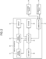
- FIG. 2 is a block diagram of a display apparatus according to one embodiment of the present invention.
- the display apparatus 20 of the present invention includes a signal receiver 21, a signal processor 22, a display 23, a user input 24, a controller 25, a storage 26 and a communicator 27, and may be for example materialized by a smart phone, a smart watch, a tablet PC, or the like user terminal.
- the display apparatus 20 may connect with a communication relay 29 by Wi-Fi and the like communication methods.
- the communication relay 29 serves as an AP.
- the communication relay 29 may be for example materialized by a wireless router.
- the display apparatus 20 may use the Wi-Fi, NFC or the like communication method to connect with an electronic device 28.
- the electronic device 28 may be for example materialized by a CCTV, a robot vacuum cleaner, a microwave oven, an air conditioner, a washing machine, a loudspeaker, and the like home appliances having Wi-Fi functions.
- the elements included in the display apparatus 20 of the present invention are not limited to one embodiment described above, and may be materialized by including additional other elements.
- the display apparatus 20 connects with the communication relay 29 of transmitting the first communication signal when the first communication signal having the first signal strength is received through the communicator 27, and stores the information about the connection with the connected communication relay 29.
- the display apparatus 20 connects with the electronic device 28 by transmitting the second communication signal having the second signal strength lower than the first signal strength to the electronic device 28.
- the display apparatus 20 transmits the stored information about the connection with the communication relay 29 to the connected electronic device 28.
- the smart phone or the like user terminal provides the information about the connection with the wireless AP to the IoT device so that the IoT device can access the wireless AP. Further, the user terminal uses an absolutely-weak signal strength to connect with the IoT device.
- the signal receiver 21 receives a broadcast signal or an image signal.
- the signal receiver 21 may be achieved in various forms in accordance with the formats of the received broadcast signal or image signal and the types of the display apparatus 20.
- the signal receiver 21 may be materialized by a tuner for receiving a radio frequency broadcast signal from a broadcasting station or a satellite signal.
- the signal receiver 21 may receive an image signal from an external device connected to the display apparatus 20, for example, a digital versatile disc (DVD) player, a universal serial bus (USB) device, etc.
- DVD digital versatile disc
- USB universal serial bus
- the signal receiver 21 is not limited to one embodiment of the present invention, and may be materialized by various forms to receive the broadcast signal or the image signal.
- the signal processor 22 performs a preset signal processing process with regard to the broadcast signal or the image signal received in the signal receiver 21.
- the signal processing process performed in the signal processor 22 there are decoding, de-interlacing, scaling, noise reduction, detail enhancement, etc., and there are no limits to the kinds of signal processing process.
- the signal processor 22 may be materialized by a system-on-chip (SoC) where such functions are integrated, or an image processing board to which individual components for independently performing the processes are mounted.
- SoC system-on-chip
- the display 23 displays an image based on the broadcast signal or image signal processed by the signal processor 22.
- the display 23 may be materialized by various types such as a plasma display panel (PDP), a liquid crystal display (LCD), an organic light emitting diode (OLED), a flexible display, etc.
- PDP plasma display panel
- LCD liquid crystal display
- OLED organic light emitting diode
- the user input 24 receives a user's input for controlling at least one function of the display apparatus 20.
- the user input 24 may include a touch screen provided in the display apparatus 20.
- the touch screen may be configured to sense a touch input position, a touched area, and a touch input.
- the touch screen may be configured to sense not only a real touch but also a proximity touch.
- the real touch refers to a case where a screen is actually touched by a user's body (e.g. a finger) or a touch pen (e.g. a pointing device, a stylus, a haptic pen, an electronic pen, etc.) provided as a touch tool.
- the proximity touch refers to a case where a user's body or a touch tool does not actually touch the screen but approaches the screen at a predetermined distance (e.g. a detectable distance shorter than or equal to 30mm).
- the user input 24 may be materialized by a keyboard, a mouse and the like connected to the display apparatus 20, or may be materialized by an input panel provided at the outer side of the display apparatus 20.
- the communicator 27 communicates with the external device.
- the communicator 27 may connect with the electronic device 28 and the communication relay 29.
- the communicator 27 may include at least one of a Wi-Fi module and an NFC module, and thus connect with the external device by the Wi-Fi or NFC communication method.
- the communicator 27 may communicate with the external device by Wi-Fi direct, Bluetooth, ZigBee, 6lowpan, or the like short-range wireless communication.
- the communicator 27 may perform pairing with the external device so as to communicate with the external device by the Bluetooth method.
- the storage 26 may be configured to store information about connection with at least one communication relay 15 which has been previously connected. That is, the storage 26 may store SSID and a password of the communication relay 15 which has been connected. Further, the SSID refers to a unique identifier attached to each header of packets transmitted through the wireless LAN, and serves to distinguish one wireless LAN from other wireless LANs. Thus, the communication relay 29 may be identified using the SSID.
- the controller 25 connects with the communication relay 29 of transmitting the first communication signal, and stores the information about the connection with the connected communication relay 29 in the storage 26, when the first communication signal having the first signal strength is received through the communicator 27.
- the information about the connection with the communication relay 29 may include the SSID of the communication relay 29 and the password for the access.
- a user may set a Wi-Fi network on a smart phone so as to access the wireless AP detected with the strongest signal strength.
- the smart phone stores the SSID of the connected wireless AP and the password for the access, and automatically accesses the wireless AP, to which the smart phone has been previously connected, without separate settings when the wireless AP is detected within an accessible range in the future.
- the controller 25 connects with the electronic device 28 by transmitting the second communication signal having the second signal strength lower than the first signal strength to the electronic device 28.
- the controller 25 executes a predetermined application program for implementing a communication relay function and transmits the second communication signal having the second signal strength lower than the first signal strength to the electronic device 28 when it is within a predetermined range from the electronic device 28.
- a predetermined application program may be achieved by a Soft-AP for performing a virtual access point operation, for example, an application program for setting tethering, mobile hot spot, or the like function.
- a predetermined application program may automatically run when the display apparatus 20 is within a predetermined range from the electronic device 28, or may be executed by a user's control.
- the display apparatus 20 when a user places the smart phone or the like display apparatus 20 near the electronic device 28 and then executes the Soft-AP, the display apparatus 20 serves as a virtual access point and the electronic device 28 connects with the display apparatus 20 by the Wi-Fi communication method.
- the display apparatus 20 may connect with the electronic device 28 by a signal strength lower than the signal strength for connecting with the communication relay 29. That is, the display apparatus 20 executes the Soft-AP, but uses a signal strength set to be weak enough to detect only the near electronic device 28, thereby allowing only the near electronic device 28 to have access thereto.
- the controller 25 may transmit the second communication signal having the second signal strength to the electronic device 28 by the NFC communication method when it is within a predetermined range from the electronic device 28. For example, when a user places the display apparatus 20 near the electronic device 28 in the state that the communicator 27 of the display apparatus 20 includes an NFC module and an NFC tag is attached to an outer side of the electronic device 28, the display apparatus 20 can connect with the electronic device 28 by the NFC communication method.
- the controller 25 controls the communicator 27 to transmit the information about the connection with the communication relay 29, which is stored in the storage 26, to the connected electronic device 28.
- the display apparatus 20 may transmit the SSID and the password as the previously stored information about the connection with the communication relay to the electronic device 28.
- the display apparatus 20 may use the SSID and the password for enabling the electronic device 28 to access the communication relay 29.
- the easy operation of placing the display apparatus 20 near the electronic device 28 is enough for a user to connect the display apparatus 20 with the electronic device 28 so that information about connection with the wireless access point can be given and the electronic device 28 can safely access the wireless access point desired by a user.
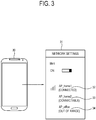
- FIG. 3 illustrates an example of showing a state of being connected to a wireless AP on a smart phone according to one embodiment of the present invention.
- a smart phone 30 displays a setting state of a Wi-Fi network on a network setting screen 31.
- the network setting screen 31 shows that 'AP_home1' 32 and 'AP_home2' 33 used at home and 'AP_office' 34 used at an office are registered as the wireless access points for various places.
- the network setting screen 31 shows that the smart phone 30 is being connected to the 'AP_home1' 32 and does not connect with the 'AP_home2' 33 and the 'AP_office' 34.
- the smart phone 30 may store the connection information for accessing each of the 'AP_home1' 32, the 'AP_home2' 33 and the 'AP_office' 34.
- the stored connection information is used for immediate access.
- Such information for connection with the wireless access point may include the SSID for accessing the wireless access point and the password needed for the access.
- FIG. 4 illustrates an example of executing a Soft-AP and connecting with a peripheral device on a smart phone according to one embodiment of the present invention.
- a smart phone 40 moves near an IoT device, e.g. a CCTV 43
- the smart phone 40 may automatically executes the Soft-AP as a predetermined application program for operating as a virtual access point.
- the Soft-AP may be for example achieved by an application program for setting tethering, mobile hot-spot, or the like function.
- a user may directly execute the Soft-AP in the state that the smart phone 40 is within a predetermined range of the CCTV 43, so that the smart phone 40 can operate as the virtual access point.
- the network setting screen 41 shows that the mobile hot-spot function is running. That is, when the mobile hot-spot function is executed, the smart phone 40 generates a virtual AP such as 'Hotspot1111' 42, and allows peripheral devices to access the 'Hotspot1111' 42. In this case, when the 'Hotspot1111' 42 is set as the virtual AP, the smart phone 40 may set a signal strength to be lower than a predetermined level so as to connect with only the CCTV 43 in the proximity thereof. Thus, the smart phone 40 may use the Wi-Fi communication method to connect with the CCTV 43.
- a virtual AP such as 'Hotspot1111' 42
- the smart phone 40 may set a signal strength to be lower than a predetermined level so as to connect with only the CCTV 43 in the proximity thereof.
- the smart phone 40 may use the Wi-Fi communication method to connect with the CCTV 43.
- FIG. 5 illustrates an example of connecting with an IoT device and providing information about connection with the wireless AP on a smart phone according to one embodiment of the present invention.
- the smart phone 50 when a user places a smart phone 50 near the CCTV 53 and for example sets the mobile hot-spot function on a network setting screen 51 of the smart phone 50, the smart phone 50 generates the virtual AP such as 'Hotspot1111' 52, and thus allows peripheral devices to access the 'Hotspot1111' 52.
- the smart phone 50 may set a signal strength to be lower than a predetermined level so as to connect with only the CCTV 53 in the proximity thereof.
- the smart phone 50 may connect with the CCTV 53 in the proximity thereof by weak signal strength.
- the smart phone 50 is set for the mobile hot-spot function with a signal strength weak enough to be detected by only the CCTV 53, so that a user can easily make the smart phone 50 connect with the CCTV 53 by just moving the smart phone 50 near the CCTV 53.
- the safe connection between the smart phone 50 near the desired CCTV 53 is achieved as a user places the smart phone 50 near the desired CCTV 53 and automatically or manually executes the Soft-AP without any separate authentication process for connecting the smart phone 50 and the CCTV 53.
- the smart phone 50 may form a security channel together with the connected CCTV 53.
- the smart phone 50 is capable of safely transmitting information to the CCTV 53 through the security channel.
- the smart phone 50 may transmit information about the connection with the wireless access point through the security channel formed for the CCTV 53. That is, the smart phone 50 transmits information such as the SSID, password, etc. of the wireless access point, which is being connected or has been connected thereto, to the CCTV 53, and makes the CCTV 53 have access to the wireless access point based on the information.
- the smart phone 50 may safely transmit the information such as the SSID, password, etc. of the wireless access point, which is being stored or received from other devices, to the CCTV 53.
- the present invention when it is desired to connect the IoT device having no display or input device to the wireless access point, it is possible to safely transmit information about the wireless access point by making a user's terminal move near the IoT device and communicate with the IoT device by the weak signal strength.
- FIG. 6 illustrates an example of using information about connection with a wireless AP, received from a smart phone, to access the wireless AP in an electronic device according to one embodiment of the present invention.
- a smart phone 61 and a CCTV 60 are connected by weak signal strength lower than a predetermined level through a Soft-AP operating as a virtual AP, a security channel is formed between the smart phone 61 and CCTV 60, so that the smart phone 61 can safely transmit the SSID and password of the wireless access point to the CCTV 60 through a security channel.
- the SSID and password of the wireless AP 62 are transmitted from the smart phone 61 to the CCTV 60 through the security channel, so that the CCTV 60 can safely access the wireless AP 62 based on the received SSID and password.
- a user can make the CCTV 60 access a desired wireless AP among the plurality of wireless APs.
- FIG. 7 illustrates an example of connecting a smart phone and a wireless AP in response to sequential button pushes, in an electronic device according to one embodiment of the present invention.
- a button provided at an outer side of a CCTV 70
- the CCTV 70 may receive information about connection with a wireless AP 72, for example, information such as the SSID of the wireless AP 72, the password needed for connection, etc. from the connected smart phone 71
- the CCTV 70 may connect with the wireless AP 72 detected with the next strongest signal strength, based on the SSID and the password received from the smart phone 71.
- the CCTV 70 when the CCTV 70 connects with the smart phone 71 by pushing the button, the CCTV 70 receives information about the connection with the wireless AP 72 from the connected smart phone 71, and directly connects with the wireless AP 72 based on the received connection information without additionally pushing the button.
- the IoT device connects with the user terminal of the strongest signal strength in response to the first user input, and connects with the wireless AP designed in the user terminal in response to the second user input. That is, a user can easily control the user terminal and the wireless AP to be connected in accordance with signal strength.
- FIG. 8 illustrates an example of connecting a smart phone and a wireless AP in response to sequential button pushes, in an electronic device according to one embodiment of the present invention.
- a button provided at an outer side of a CCTV 80
- the wireless AP 83 is not the device desired by a user, it is possible to connect with a smart phone 81 detectable with the next strongest signal strength by pushing the button of the CCTV 80 again.
- the CCTV 80 may receive information about connection with a wireless AP 82, for example, information such as the SSID of the wireless AP 82, the password needed for connection, etc. from the connected smart phone 81, and connect with the wireless AP 82 based on the received information.
- the CCTV 80 may connect with the smart phone 81 and receive the information about the connection with the wireless AP 82 by pushing the button twice, and connect with the wireless AP 82 based on the connection information received from the smart phone 82 by pushing the button three times.
- the IoT device can connect with the devices in order from the device of the strong signal strength to the device of the weak signal strength in response to sequential user inputs. That is, a user's easy control is enough to connect the user terminal and the desired wireless AP.
- FIG. 9 is a flowchart of showing a control method of an electronic device according to one embodiment of the present invention.
- the electronic device connects with the user terminal of transmitting the first communication signal.
- at operation S90 at least one of the Wi-Fi and NFC communication methods is used to connect with the user terminal.
- the information about the connection with the communication relay is received from the connected user terminal.
- the information about the connection with the communication relay may include information about the SSID for accessing the communication relay and the password needed for the access.
- the communication relay of transmitting the second communication signal having the second signal strength lower than the first signal strength is connected based on the received connection information.
- the IoT device can safely access the wireless AP via the smart phone or the like user terminal. Further, the signal strength of the communication is used to thereby safely receive information for accessing the wireless AP from the user terminal, and thus connect with the wireless AP.
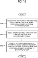
- FIG. 10 is a flowchart of showing a control method of an electronic device according to one embodiment of the present invention.
- the electronic device connects with the user terminal, which transmits the first communication signal having the first signal strength, in response to the first input of a user.
- the information about the connection with the communication relay is received from the connected user terminal.
- the information about the connection with the communication relay may include information about the SSID for accessing the communication relay and the password needed for the access.
- the communication relay of transmitting the second communication signal having the second signal strength lower than the first signal strength is connected in response to the second input of a user.
- the first input and the second input of a user may include inputs using at least one button provided at the outer side of the electronic device. Further, the first input and the second input of a user may include inputs using an input panel provided at the outer side of the electronic device. Besides, the electronic device can receive a user's input in various ways.
- the CCTV 70 may receive information, such as the SSID of the wireless AP 72, the password needed for the access, etc. from the connected smart phone 71.
- the CCTV 70 may connect with the wireless AP 72 detectable with the next strongest signal strength by using the SSID and the password received from the smart phone 71.
- FIG. 11 is a flowchart of showing a control method of an electronic device according to one embodiment of the present invention.
- the electronic device connects with the user terminal of transmitting the first communication signal having the first signal strength, when the user terminal is placed within a predetermined range from the electronic device.
- the user terminal in the proximity of the electronic device executes the Soft-AP for operating as the virtual AP, and sets the signal strength to be weak enough to be detectable by only the near electronic device.
- the electronic device detects the strongest signal strength of the user terminal in the proximity thereof and connects with the user terminal.
- a security channel may be formed between them so that the electronic device and the user terminal can exchange data and information with each other through the security channel.
- the electronic device and the user terminal may be connected by the NFC communication method.
- an NFC channel may be formed between the electronic device and the user terminal, so that the electronic device and the user terminal can exchange data and information with each other through the NFC channel.
- the information about the connection with the communication relay is received from the connected user terminal.
- the information about the connection with the communication relay may include information about the SSID for accessing the communication relay and the password needed for the access.
- the information about the connection with the communication relay may include information about the connection with the wireless AP, to which the user terminal is being connected, or information about the connection with the wireless AP, which has been registered in the user terminal.
- the information about the connection with the communication relay may include information about the connection with the wireless AP, which the user terminal receives from another external device.
- the communication relay of transmitting the second communication signal having the second signal strength lower than the first signal strength is connected based on the received connection information. That is, the electronic device can access the wireless AP detected with the next strongest signal strength, based on the information such as the SSID of the wireless AP and the password received from the user terminal detected with the strongest signal strength.
- the IoT device connects with the user terminal with the strongest signal strength and safely receives the information about the connection with the wireless AP. Further, the information received from the user terminal is used to have access to the wireless AP.
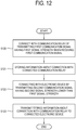
- FIG. 12 is a flowchart of showing a control method of a display apparatus according to one embodiment of the present invention.
- the display apparatus connects with the communication relay of transmitting the first communication signal when the first communication signal having the first signal strength is received.
- the information about the connection with the connected communication relay is stored.
- the information about the connection with the communication relay may include information about the SSID for accessing the communication relay and the password needed for the access. For example, as shown in FIG.
- the smart phone 30 may display the network setting screen 31 of showing the setting state of the Wi-Fi network, in which the smart phone 30 is being connected to the 'AP_home1' 32 among the registered wireless access points, and does not connect with the 'AP_home2' 33 and the 'AP_office' 34.
- the SSID of the 'AP_home1' 32 and the password needed for the access may be stored as the information about the connection with the currently connected 'AP_home1' 32.
- the SSID and the password for accessing each of them may be stored.
- the connection is achieved by transmitting the second communication signal having the second signal strength lower than the first signal strength to the electronic device.
- the Soft-AP function may be implemented in the proximity of the electronic device. Thus, only the electronic device in the proximity of the display apparatus is allowed to detect the second communication signal transmitted from the display apparatus and connected to the display apparatus.
- the stored information about the connection with the communication relay is transmitted to the connected electronic device.
- the smart phone or the like user terminal provides the information about the connection with the wireless AP to the IoT device so that the IoT device can have access to the wireless AP. Further, the user terminal connects with the IoT device based on the signal strength weak enough to be detectable by only the device in the proximity thereof, and it is thus possible to safely transmit the information.
- FIG. 13 is a flowchart of showing a control method of a display apparatus according to one embodiment of the present invention.
- a predetermined application program is executed so that the connection is achieved by transmitting the second communication signal having the second signal strength to the electronic device.
- a predetermined application program may be achieved by the Soft-AP. For example, as shown in FIG.
- the smart phone 50 when a user places the smart phone 50 near the CCTV 53 and for example starts the mobile hot-spot function through the network setting screen 51 of the smart phone 50, the smart phone 50 generates the virtual AP such as the 'Hotspot1111' 52 and thus allows access of peripheral devices to the 'Hotspot1111' 52.
- the smart phone 50 may set the virtual AP, i.e. the 'Hotspot1111' 52 to have the signal strength lower than a predetermined level so that only the CCTV 53 in the proximity thereof can have access.
- the smart phone 50 can access the CCTV 53 within a proximity range by the weak signal strength.
- the information about the connection with the communication relay is transmitted to the connected electronic device.
Description
- The present invention relates to an electronic device, a display apparatus and a control method thereof, and more particularly to an electronic device, a display apparatus and a control method thereof, in which the electronic device is connected to a wireless access point through a terminal of a user.
- With recent development of wireless technology, people have used a wireless network instead of a wired network. Since the wireless technology is free from constraint on mobility of the wired network, researches have been actively made on various techniques using the wireless network.
- In a case of a wireless local area network (WLAN), so-called wireless fidelity (Wi-Fi) allows a smart phone and the like to use the Internet within a predetermined range from an access point (AP).
- Besides the smart phone, various Internet-of-things (IoT) have recently been configured to have a Wi-Fi function. For example, most of a closed circuit television (CCTV), a robot vacuum cleaner, a microwave oven, an air conditioner,
a washing machine, a loudspeaker, and the like electronic products can have access to the Internet through Wi-Fi. - However, such an IoT device may be constrained from having access to the wireless AP since it does not have a display, an input unit, etc.
- Further, when the IoT device accesses the wireless AP, there may be security concerns with a separate registration process required of a user, access to another hub device undesired by a user, etc.
-
US-2013/252547-A1 relates to a method of connecting an Access Point (AP). The method includes, if a device having a nearfield wireless communication tag is tagged with a mobile terminal apparatus having a nearfield wireless communication reader, providing connecting information stored on the device to the mobile terminal apparatus, connecting the mobile terminal apparatus, receiving AP information from the connected mobile terminal apparatus, and connecting to an AP using the received AP information. -
EP-2814273-A1 relates to a method of provisioning an appliance to connect to a Wi-Fi network including a mobile device having an encryption key to enable secure communication in the Wi-Fi network, and a means to wirelessly communicate with the appliance. A wireless communication device and a software protocol in the appliance are configured to operate in an unsecured short-range configuration mode where transmission power is not reduced. By placing the wireless communication device into the short-range configuration mode and moving the mobile device to a position within the short range to establish communication with the wireless communication device, the encryption key may be transmitted from the mobile device to the appliance via the wireless communication device without security. The wireless communication device may then be placed into the long-range mode to securely connect to the Wi-Fi network. -
WO-2015/119394-A1 relates to a network connection method of a home appliance, a network connected system for a home appliance, and a home appliance, the network connection method comprising: a step in which a first terminal device receives an authentication key of an access point device and transmits the authentication key to the access point device, and the access point device verifies the authentication key; a step in which at least one home appliance is connected to the first terminal device, and the first terminal device transmits, to the at least one home appliance, an identification number of the access point device and the authentication key; and a step in which the at least one home appliance is connected to the access point device on the basis of the identification number and the authentication key. - Accordingly, an object of the present invention is to provide an electronic device, and a control method thereof, in which a user's terminal is used to safely connect the electronic device to the wireless access point.
- Further, another object of the present invention is to provide an electronic device, and a control method thereof, in which strength of a signal for communication between a user's terminal and the electronic device is used to connect the electronic device to a wireless access point.
- Further, still another object of the present invention is to provide an electronic device, and a control method thereof, by which a user can easily connect the electronic device and a wireless access point.
- The invention is defined by a first independent claim in the form of a device (claim 1) and a second independent claim in the form of a method (claim 5). Further aspects of the invention are outlined in the dependent claims. When the term "embodiment" is used to describe an unclaimed combination of features, it has to be understood as referring to examples useful for understanding the present invention.
- Also disclosed is an electronic device including: a communicator configured to communicate with an external device; and a controller configured to perform control for connecting with a user terminal of transmitting a first communication signal having a first signal strength when the first communication signal is received through the communicator, receiving information about connection with a communication relay from the connected user terminal, and connecting with the communication relay of transmitting a second communication signal having a second signal strength lower than the first signal strength through the communicator based on the received connection information. According to such an embodiment of the present invention, the IoT device can have safe access to the wireless AP through the user terminal such as the smart phone or the like. Further, the IoT device can connect with each of the user terminal and the wireless AP in accordance with the signal strength of the communication.
- The electronic device may further include a user input configured to receive an input of a user, wherein the controller connects with the user terminal of transmitting the first communication signal having the first signal strength in response to the first input of the user, and connects with the communication relay of transmitting the second communication signal having the second signal strength in response to the second input of the user. Thus, the IoT device connects with the user terminal of the strongest signal strength in response to the first user input, and connects with the wireless AP designated by the user terminal in response to the second user input. That is, a user can easily control for connection with the user terminal, and connect the electronic device with the wireless AP based on the information about the connection with the wireless AP desired for connection in the user terminal, for example, the SSID and the password.
- The controller may connect with the user terminal of transmitting the first communication signal having the first signal strength based on repetitive inputs of a user, when connecting with the external device of transmitting a third communication signal having a third signal strength higher than the first signal strength based on the first input of the user. Thus, the IoT device can connect with the user terminal of the next strongest signal strength in response to repetitive inputs of a user, when connecting with the undesired device having the strongest signal strength in response to the first input of a user.
- The controller may connect with the user terminal of transmitting the first communication signal having the first signal strength, when the user terminal is placed within a predetermined range from the electronic device. Thus, when the user terminal moves near the IoT device, it is possible to connect with the user terminal by the strongest signal strength.
- The information about the connection with the communication relay may include a service set identifier (SSID) for accessing the communication relay and a password needed for the access. Thus, information for connecting with the AP is obtained from the user terminal, and used for connection with the wireless AP.
- The user input includes at least one button provided at an outer side of the electronic device. Thus, the IoT device is connected to the user terminal and the wireless AP in sequence by only the button input in accordance with the signal strength.
- The communicator may include at least one of a wireless fidelity (Wi-Fi) module and a near field communication (NFC) module. Thus, the IoT device can connect with the user terminal in the proximity thereof by the Wi-Fi or NFC communication method.
- Also disclosed is a method of controlling an electronic device, the method including: connecting with a user terminal of transmitting a first communication signal having a first signal strength when the first communication signal is received through a communicator; receiving information about connection with a communication relay from the connected user terminal; and connecting with the communication relay of transmitting a second communication signal having a second signal strength lower than the first signal strength through the communicator based on the received connection information. According to such an embodiment of the present invention, the IoT device can have safe access to the wireless AP through the user terminal such as the smart phone or the like. Further, the IoT device can connect with each of the user terminal and the wireless AP in accordance with the signal strength of the communication.
- The method may further include connecting with the user terminal of transmitting the first communication signal having the first signal strength in response to the first input of the user; and connecting with the communication relay of transmitting the second communication signal having the second signal strength in response to the second input of the user. Thus, the IoT device connects with the user terminal of the strongest signal strength in response to the first user input, and connects with the wireless AP designated by the user terminal in response to the second user input. That is, a user can easily control for connection with the user terminal, and connect the electronic device with the wireless AP based on the information about the connection with the wireless AP desired for connection in the user terminal, for example, the SSID and the password.
- The method may further include connecting with the user terminal of transmitting the first communication signal having the first signal strength based on repetitive inputs of a user, when connecting with the external device of transmitting a third communication signal having a third signal strength higher than the first signal strength based on the first input of the user. Thus, the IoT device can connect with the user terminal of the next strongest signal strength in response to repetitive inputs of a user, when connecting with the undesired device having the strongest signal strength in response to the first input of a user.
- The method may further include connecting with the user terminal of transmitting the first communication signal having the first signal strength, when the user terminal is placed within a predetermined range from the electronic device. Thus, when the user terminal moves near the IoT device, it is possible to connect with the user terminal by the strongest signal strength.
- The information about the connection with the communication relay may include an SSID for accessing the communication relay and a password needed for the access. Thus, information for connecting with the AP is obtained from the user terminal, and used for connection with the wireless AP.
- Also disclosed is a display apparatus including: a display; a communicator configured to communicate with an external device; a storage; a controller configured to perform control for connecting with a communication relay of transmitting a first communication signal having a first signal strength when the first communication signal is received through the communicator, storing information about the connection with the connected communication relay in the storage, connecting with an electronic device by transmitting a second communication signal having a second signal strength lower than the first signal strength to the electronic device, and controlling the communicator to transmit the stored information about the connection with the communication relay to the connected electronic device. According to such an embodiment of the present invention, the smart phone or the like user terminal can provide the information about the connection with the wireless AP to the IoT device so that the IoT device can have access to the wireless AP. Further, the user terminal uses signal strength weak enough to be sensed by only the proximity device, thereby connecting with the IoT device and safely transmitting the information.
- The controller may transmit the second communication signal having the second signal strength to the electronic device by transmitting a predetermined application program for implementing a communication relay function in a case of being placed within a predetermined range from the electronic device. Here, the predetermined application program may be achieved by a software enabled access point (Soft-AP). Thus, when the user terminal moves near the IoT device, the software serving as the wireless AP is executed so that the user terminal can use an absolutely-weak signal strength to connect with the IoT device. That is, when the IoT device receives a signal having the absolutely-weak signal strength from the user terminal in the proximity thereof, the user terminal can connect with the IoT device by a relatively strong signal strength.
- The communicator may include at least one of a Wi-Fi module and an NFC module. Thus, the user terminal can connect with the IoT device in the proximity thereof by the Wi-Fi or NFC communication method.
- The controller may transmit the second communication signal having the second signal strength to the electronic device by an NFC communication method, in a case of being placed within a predetermined range from the electronic device. Thus, when the user terminal moves near the IoT device, the NFC communication method is used for connection with the IoT device by an absolutely-weak signal strength.
- The information about the connection with the communication relay may include an SSID for accessing the communication relay and a password needed for the access. Thus, the user terminal stores the information about the connection with the wireless AP, and provides the stored connection information to the IoT device, thereby making the IoT device have access to the wireless AP.
- Also disclosed is a method of controlling a display apparatus, the method including: connecting with a communication relay of transmitting a first communication signal having a first signal strength when the first communication signal is received through the communicator; storing information about the connection with the connected communication relay; connecting with an electronic device by transmitting a second communication signal having a second signal strength lower than the first signal strength to the electronic device; and transmitting the stored information about the connection with the communication relay to the connected electronic device. According to such an embodiment of the present invention, the smart phone or the like user terminal can provide the information about the connection with the wireless AP to the IoT device so that the IoT device can have access to the wireless AP. Further, the user terminal uses signal strength weak enough to be sensed by only the proximity device, thereby connecting with the IoT device and safely transmitting the information.
- The method may further include transmitting the second communication signal having the second signal strength to the electronic device by transmitting a predetermined application program for implementing a communication relay function in a case of being placed within a predetermined range from the electronic device. Here, the predetermined application program may be achieved by a Soft-AP. Thus, when the user terminal moves near the IoT device, the software serving as the wireless AP is executed so that the user terminal can use an absolutely-weak signal strength to connect with the IoT device. That is, when the IoT device receives a signal having the absolutely-weak signal strength from the user terminal in the proximity thereof, the user terminal can connect with the IoT device by a relatively strong signal strength.
- The information about the connection with the communication relay may include an SSID for accessing the communication relay and a password needed for the access. Thus, the user terminal stores the information about the connection with the wireless AP, and provides the stored connection information to the IoT device, thereby making the IoT device have access to the wireless AP.
- As described above, according to the present invention, strength of a signal for communication between a user's terminal and an electronic device is used to connect the electronic device to a wireless access point.
- Further, according to the present invention, a user's terminal is used to safely connect an electronic device to the wireless access point.
- Further, according to the present invention, it is easy for a user to connect an electronic device and a wireless access point.
-
-
FIG. 1 is a block diagram of an electronic device according to one embodiment of the present invention. -
FIG. 2 is a block diagram of a display apparatus according to one embodiment of the present invention. -
FIG. 3 illustrates an example of showing a state of being connected to a wireless AP on a smart phone according to one embodiment of the present invention. -
FIG. 4 illustrates an example of executing a Soft-AP and connecting with a peripheral device, on a smart phone according to one embodiment of the present invention. -
FIG. 5 illustrates an example of connecting with an IoT device and providing information about connection with the wireless AP, on a smart phone according to one embodiment of the present invention. -
FIG. 6 illustrates an example of using information about connection with a wireless AP, received from a smart phone, to access the wireless AP in an electronic device according to one embodiment of the present invention. -
FIG. 7 illustrates an example of connecting a smart phone and a wireless AP in response to sequential button pushes, in an electronic device according to one embodiment of the present invention. -
FIG. 8 illustrates an example of connecting a smart phone and a wireless AP in response to sequential button pushes, in an electronic device according to one embodiment of the present invention. -
FIG. 9 is a flowchart of showing a control method of an electronic device according to one embodiment of the present invention. -
FIG. 10 is a flowchart of showing a control method of an electronic device according to one embodiment of the present invention. -
FIG. 11 is a flowchart of showing a control method of an electronic device according to one embodiment of the present invention. -
FIG. 12 is a flowchart of showing a control method of a display apparatus according to one embodiment of the present invention. -
FIG. 13 is a flowchart of showing a control method of a display apparatus according to one embodiment of the present invention. - Hereinafter, embodiments of the present invention will be described in detail with reference to accompanying drawings so as to be easily realized by a person having an ordinary skill in the art to which the present invention pertains. The present invention may be embodied in various different forms, and not limited to the embodiments set forth herein. To describe the present invention clearly, parts unrelated to the description are omitted, and the same or like numerals refer to the same or like elements throughout.
- Below, features of elements included in an electronic device according to the present invention will be first described in detail with reference to
FIG. 1. FIG. 1 is a block diagram of an electronic device according to one embodiment of the present invention. As shown inFIG. 1 , anelectronic device 10 according to one embodiment of the present invention includes auser input 11, acontroller 12 and acommunicator 13, and may be for example materialized by home appliances, such as a closed circuit television (CCTV), a robot vacuum cleaner, a microwave oven, an air conditioner, a washing machine, a loudspeaker, and the like having a wireless fidelity (Wi-Fi) function. Theelectronic device 10 may connect with auser terminal 14 through a communication method such as Wi-Fi, near field communication (NFC), etc. Theuser terminal 14 may be materialized by a display apparatus, and may be for example achieved by a user's smart phone, smart watch, tablet personal computer, etc. Theelectronic device 10 may connect with acommunication relay 15 through a communication method such as Wi-Fi, etc. Thecommunication relay 15 functions as an access point (AP). Thecommunication relay 15 is one of devices that constitute a wireless local area network (WLAN), and has routing and network address translation (NAT) functions to thereby for example serve as a relay of connecting with a wired LAN for the Internet. Thecommunication relay 15 may be for example materialized by a wireless router. The elements included in theelectronic device 10 according to the present invention are not limited to the foregoing embodiment, and may include other additional elements. - The
electronic device 10 connects with theuser terminal 14 of transmitting a first communication signal when the first communication signal having a first signal strength is received through thecommunicator 13. Theelectronic device 10 receives information about connection with thecommunication relay 15 from the connecteduser terminal 14. Theelectronic device 10 connects with thecommunication relay 15, which transmits a second communication signal having a second signal strength lower than the first signal strength through thecommunication 13, based on the received connection information. - According to this embodiment of the present invention, the
electronic device 10 has an effect on safely accessing the wireless access point through theuser terminal 14 such as a smart phone or the like. Further, it is advantageous that the strength of the signal for the communication between theelectronic device 10 and theuser terminal 14 is used to connect theelectronic device 10 and the wireless access point. - The
communicator 13 communicates with the external device. Thecommunicator 13 may connect with theuser terminal 14 and thecommunication relay 15. Thecommunicator 13 may include at least one of a Wi-Fi module and an NFC module, and thus connect with the external device by the Wi-Fi or NFC communication method. Alternatively, thecommunicator 13 may communicate with the external device through Wi-Fi direct, Bluetooth, ZigBee, low power wireless personal area network (6LoWPAN) or the like short-range wireless communication method. Thecommunicator 13 may perform pairing with the external device so as to communicate with the external device through the Bluetooth method. - The
user input 11 receives a user's input for controlling at least one function of theelectronic device 10. For example, theuser input 11 may include at least one button provided at an outer side of theelectronic device 10. Alternatively, theuser input 11 may be materialized by a keyboard, a mouse, etc. or be materialized by an input panel provided at the outer side of theelectronic device 10. Further, theuser input 11 may receive a user's input from a remote controller. - According to one embodiment, the
electronic device 10 may further include a storage (not shown). The storage may be configured to store information about connection with at least onecommunication relay 15 which has been previously connected. For example, the storage may store SSID of thecommunication relay 15 which has been connected using theuser terminal 14 and a password needed for connection. Further, the storage may store a service set identifier (SSID) and a password for thecommunication relay 15, received from theuser terminal 14. The SSID refers to a unique identifier attached to each header of packets transmitted through the wireless LAN, and serves to distinguish one wireless LAN from other wireless LANs. Thus, thecommunication relay 15 may be identified using the SSID. - The
controller 12 connects with theuser terminal 14 of transmitting the first communication signal when the first communication signal having the first signal strength is received through thecommunicator 13. According to one embodiment, thecontroller 12 may connect with theuser terminal 14 of transmitting the first communication signal having the first signal strength, when theuser terminal 14 is located within a predetermined range from theelectronic device 10. In this case, theelectronic device 10 is located near theuser terminal 14, and thus senses the strength of the first signal transmitted from theuser terminal 14 by the strongest signal strength as compared with those of other devices. - For example, when a user places the
user terminal 14 near theelectronic device 10 and executes software enabled access point (Soft-AP) for a virtual access point operation, theuser terminal 14 serves as a virtual access point and enables theelectronic device 10 to connect with theuser terminal 14 by the Wi-Fi communication method. Alternatively, when a user places theuser terminal 14 near theelectronic device 10 in the state that thecommunicator 13 includes an NFC module and an NFC tag is attached to an outer side of the electronic device, theelectronic device 10 can connect with theuser terminal 14 by the NFC communication method. - The
controller 12 performs control to receive the information about the connection with thecommunication relay 15 from the connected theuser terminal 14, and connect with a communication relay of transmitting the second communication signal having the second signal strength lower than the first signal strength through thecommunicator 13 based on the received connection information. Here, the information about the connection with thecommunication relay 15 includes SSID and password for accessing thecommunication relay 15. For example, when a user places theuser terminal 14 near theelectronic device 10 and theuser terminal 14 and theelectronic device 10 are connected by the Wi-Fi or NFC communication method, theelectronic device 10 receives information such as the SSID, the password, etc. for accessing the communication relay from theuser terminal 14, and accesses thecommunication relay 15 corresponding to the received information. - According to one embodiment, the
controller 12 connects with theuser terminal 14, which transmits the first communication signal having the first signal strength, in response to a user's first input, and connects with thecommunication relay 15, which transmits the second communication signal having the second signal strength lower than the first signal strength, in response to a user's second input. For example, by pushing a button provided at the outer side of theelectronic device 10, it is possible to connect with theuser terminal 14 detected with the strongest signal strength within a near range from theelectronic device 10. Further, by pushing the button again, it is possible to connect with thecommunication relay 15 detected with the next strongest signal strength. That is, in response to a user's sequential inputs to theelectronic device 10, theelectronic device 10 may sequentially connect with devices in order from the device of the strong signal strength to the device of the weak signal strength. - According to one embodiment, the
controller 12 may connect with theuser terminal 14 of transmitting the first communication signal having the first signal strength in response to a user's repetitive inputs, when connecting with an external device of transmitting a third communication signal having a third signal strength higher than the first signal strength in response to a user's first input. For example, by pushing the button provided at the outer side of theelectronic device 10, it is possible to connect with a device detected with the strongest signal strength at the location of theelectronic device 10. In this case, when the connected device is not desired by a user, the user pushes the button again so as to connect with theuser terminal 14 detected with the next strongest signal strength. That is, theelectronic device 10 connects with devices in order from the device of the strong signal strength to the device of the weak signal strength in response to a user's simple control, thereby connecting with theuser terminal 14. - According to such an embodiment of the present invention, the
electronic device 10 receives the information for accessing the wireless AP from theuser terminal 14, and thus safely accesses the wireless AP. Further, only the operation of placing theuser terminal 14 near theelectronic device 10 is enough for a user to make theelectronic device 10 access the wireless AP. -
FIG. 2 is a block diagram of a display apparatus according to one embodiment of the present invention. As shown inFIG. 2 , thedisplay apparatus 20 of the present invention includes asignal receiver 21, asignal processor 22, adisplay 23, auser input 24, acontroller 25, astorage 26 and acommunicator 27, and may be for example materialized by a smart phone, a smart watch, a tablet PC, or the like user terminal. Thedisplay apparatus 20 may connect with acommunication relay 29 by Wi-Fi and the like communication methods. Thecommunication relay 29 serves as an AP. Thecommunication relay 29 may be for example materialized by a wireless router. - The
display apparatus 20 may use the Wi-Fi, NFC or the like communication method to connect with anelectronic device 28. Theelectronic device 28 may be for example materialized by a CCTV, a robot vacuum cleaner, a microwave oven, an air conditioner, a washing machine, a loudspeaker, and the like home appliances having Wi-Fi functions. The elements included in thedisplay apparatus 20 of the present invention are not limited to one embodiment described above, and may be materialized by including additional other elements. - The
display apparatus 20 connects with thecommunication relay 29 of transmitting the first communication signal when the first communication signal having the first signal strength is received through thecommunicator 27, and stores the information about the connection with theconnected communication relay 29. Thedisplay apparatus 20 connects with theelectronic device 28 by transmitting the second communication signal having the second signal strength lower than the first signal strength to theelectronic device 28. Thedisplay apparatus 20 transmits the stored information about the connection with thecommunication relay 29 to the connectedelectronic device 28. - According to such an embodiment of the present invention, the smart phone or the like user terminal provides the information about the connection with the wireless AP to the IoT device so that the IoT device can access the wireless AP. Further, the user terminal uses an absolutely-weak signal strength to connect with the IoT device.
- The
signal receiver 21 receives a broadcast signal or an image signal. Thesignal receiver 21 may be achieved in various forms in accordance with the formats of the received broadcast signal or image signal and the types of thedisplay apparatus 20. For example, thesignal receiver 21 may be materialized by a tuner for receiving a radio frequency broadcast signal from a broadcasting station or a satellite signal. Alternatively, thesignal receiver 21 may receive an image signal from an external device connected to thedisplay apparatus 20, for example, a digital versatile disc (DVD) player, a universal serial bus (USB) device, etc. Like this, thesignal receiver 21 is not limited to one embodiment of the present invention, and may be materialized by various forms to receive the broadcast signal or the image signal. - The
signal processor 22 performs a preset signal processing process with regard to the broadcast signal or the image signal received in thesignal receiver 21. As an example of the signal processing process performed in thesignal processor 22, there are decoding, de-interlacing, scaling, noise reduction, detail enhancement, etc., and there are no limits to the kinds of signal processing process. Thesignal processor 22 may be materialized by a system-on-chip (SoC) where such functions are integrated, or an image processing board to which individual components for independently performing the processes are mounted. - The
display 23 displays an image based on the broadcast signal or image signal processed by thesignal processor 22. There are no limits to the types of thedisplay 23, and therefore thedisplay 23 may be materialized by various types such as a plasma display panel (PDP), a liquid crystal display (LCD), an organic light emitting diode (OLED), a flexible display, etc. - The
user input 24 receives a user's input for controlling at least one function of thedisplay apparatus 20. For example, theuser input 24 may include a touch screen provided in thedisplay apparatus 20. The touch screen may be configured to sense a touch input position, a touched area, and a touch input. Further, the touch screen may be configured to sense not only a real touch but also a proximity touch. Here, the real touch refers to a case where a screen is actually touched by a user's body (e.g. a finger) or a touch pen (e.g. a pointing device, a stylus, a haptic pen, an electronic pen, etc.) provided as a touch tool. Further, the proximity touch refers to a case where a user's body or a touch tool does not actually touch the screen but approaches the screen at a predetermined distance (e.g. a detectable distance shorter than or equal to 30mm). Alternatively, theuser input 24 may be materialized by a keyboard, a mouse and the like connected to thedisplay apparatus 20, or may be materialized by an input panel provided at the outer side of thedisplay apparatus 20. - The
communicator 27 communicates with the external device. Thecommunicator 27 may connect with theelectronic device 28 and thecommunication relay 29. Thecommunicator 27 may include at least one of a Wi-Fi module and an NFC module, and thus connect with the external device by the Wi-Fi or NFC communication method. Alternatively, thecommunicator 27 may communicate with the external device by Wi-Fi direct, Bluetooth, ZigBee, 6lowpan, or the like short-range wireless communication. Thecommunicator 27 may perform pairing with the external device so as to communicate with the external device by the Bluetooth method. - The
storage 26 may be configured to store information about connection with at least onecommunication relay 15 which has been previously connected. That is, thestorage 26 may store SSID and a password of thecommunication relay 15 which has been connected. Further, the SSID refers to a unique identifier attached to each header of packets transmitted through the wireless LAN, and serves to distinguish one wireless LAN from other wireless LANs. Thus, thecommunication relay 29 may be identified using the SSID. - The
controller 25 connects with thecommunication relay 29 of transmitting the first communication signal, and stores the information about the connection with theconnected communication relay 29 in thestorage 26, when the first communication signal having the first signal strength is received through thecommunicator 27. The information about the connection with thecommunication relay 29 may include the SSID of thecommunication relay 29 and the password for the access. For example, a user may set a Wi-Fi network on a smart phone so as to access the wireless AP detected with the strongest signal strength. In this case, the smart phone stores the SSID of the connected wireless AP and the password for the access, and automatically accesses the wireless AP, to which the smart phone has been previously connected, without separate settings when the wireless AP is detected within an accessible range in the future. - The
controller 25 connects with theelectronic device 28 by transmitting the second communication signal having the second signal strength lower than the first signal strength to theelectronic device 28. According to one embodiment, thecontroller 25 executes a predetermined application program for implementing a communication relay function and transmits the second communication signal having the second signal strength lower than the first signal strength to theelectronic device 28 when it is within a predetermined range from theelectronic device 28. Here, a predetermined application program may be achieved by a Soft-AP for performing a virtual access point operation, for example, an application program for setting tethering, mobile hot spot, or the like function. In this case, a predetermined application program may automatically run when thedisplay apparatus 20 is within a predetermined range from theelectronic device 28, or may be executed by a user's control. - For example, when a user places the smart phone or the
like display apparatus 20 near theelectronic device 28 and then executes the Soft-AP, thedisplay apparatus 20 serves as a virtual access point and theelectronic device 28 connects with thedisplay apparatus 20 by the Wi-Fi communication method. In this case, thedisplay apparatus 20 may connect with theelectronic device 28 by a signal strength lower than the signal strength for connecting with thecommunication relay 29. That is, thedisplay apparatus 20 executes the Soft-AP, but uses a signal strength set to be weak enough to detect only the nearelectronic device 28, thereby allowing only the nearelectronic device 28 to have access thereto. - According to another embodiment, the
controller 25 may transmit the second communication signal having the second signal strength to theelectronic device 28 by the NFC communication method when it is within a predetermined range from theelectronic device 28. For example, when a user places thedisplay apparatus 20 near theelectronic device 28 in the state that thecommunicator 27 of thedisplay apparatus 20 includes an NFC module and an NFC tag is attached to an outer side of theelectronic device 28, thedisplay apparatus 20 can connect with theelectronic device 28 by the NFC communication method. - The
controller 25 controls thecommunicator 27 to transmit the information about the connection with thecommunication relay 29, which is stored in thestorage 26, to the connectedelectronic device 28. For example, when a user places thedisplay apparatus 20 near theelectronic device 28 and thedisplay apparatus 20 and theelectronic device 28 are connected by the Wi-Fi or NFC communication method, thedisplay apparatus 20 may transmit the SSID and the password as the previously stored information about the connection with the communication relay to theelectronic device 28. Thus, thedisplay apparatus 20 may use the SSID and the password for enabling theelectronic device 28 to access thecommunication relay 29. - Like this, according to the present invention, only the easy operation of placing the
display apparatus 20 near theelectronic device 28 is enough for a user to connect thedisplay apparatus 20 with theelectronic device 28 so that information about connection with the wireless access point can be given and theelectronic device 28 can safely access the wireless access point desired by a user. -
FIG. 3 illustrates an example of showing a state of being connected to a wireless AP on a smart phone according to one embodiment of the present invention. As shown inFIG. 3 , asmart phone 30 displays a setting state of a Wi-Fi network on anetwork setting screen 31. For example, thenetwork setting screen 31 shows that 'AP_home1' 32 and 'AP_home2' 33 used at home and 'AP_office' 34 used at an office are registered as the wireless access points for various places. Further, thenetwork setting screen 31 shows that thesmart phone 30 is being connected to the 'AP_home1' 32 and does not connect with the 'AP_home2' 33 and the 'AP_office' 34. - According to one embodiment, the
smart phone 30 may store the connection information for accessing each of the 'AP_home1' 32, the 'AP_home2' 33 and the 'AP_office' 34. When thesmart phone 30 enters a region accessible to each wireless access point, the stored connection information is used for immediate access. Such information for connection with the wireless access point may include the SSID for accessing the wireless access point and the password needed for the access. -
FIG. 4 illustrates an example of executing a Soft-AP and connecting with a peripheral device on a smart phone according to one embodiment of the present invention. As shown inFIG. 4 , when asmart phone 40 moves near an IoT device, e.g. aCCTV 43, thesmart phone 40 may automatically executes the Soft-AP as a predetermined application program for operating as a virtual access point. The Soft-AP may be for example achieved by an application program for setting tethering, mobile hot-spot, or the like function. Alternatively, a user may directly execute the Soft-AP in the state that thesmart phone 40 is within a predetermined range of theCCTV 43, so that thesmart phone 40 can operate as the virtual access point. - In the
smart phone 40, thenetwork setting screen 41 shows that the mobile hot-spot function is running. That is, when the mobile hot-spot function is executed, thesmart phone 40 generates a virtual AP such as 'Hotspot1111' 42, and allows peripheral devices to access the 'Hotspot1111' 42. In this case, when the 'Hotspot1111' 42 is set as the virtual AP, thesmart phone 40 may set a signal strength to be lower than a predetermined level so as to connect with only theCCTV 43 in the proximity thereof. Thus, thesmart phone 40 may use the Wi-Fi communication method to connect with theCCTV 43. -
FIG. 5 illustrates an example of connecting with an IoT device and providing information about connection with the wireless AP on a smart phone according to one embodiment of the present invention. As shown inFIG. 5 , when a user places asmart phone 50 near theCCTV 53 and for example sets the mobile hot-spot function on anetwork setting screen 51 of thesmart phone 50, thesmart phone 50 generates the virtual AP such as 'Hotspot1111' 52, and thus allows peripheral devices to access the 'Hotspot1111' 52. In this case, when the 'Hotspot1111' 52 is set as the virtual AP, thesmart phone 50 may set a signal strength to be lower than a predetermined level so as to connect with only theCCTV 53 in the proximity thereof. Thus, thesmart phone 50 may connect with theCCTV 53 in the proximity thereof by weak signal strength. - That is, the
smart phone 50 is set for the mobile hot-spot function with a signal strength weak enough to be detected by only theCCTV 53, so that a user can easily make thesmart phone 50 connect with theCCTV 53 by just moving thesmart phone 50 near theCCTV 53. Thus, the safe connection between thesmart phone 50 near the desiredCCTV 53 is achieved as a user places thesmart phone 50 near the desiredCCTV 53 and automatically or manually executes the Soft-AP without any separate authentication process for connecting thesmart phone 50 and theCCTV 53. - According to one embodiment, when the
smart phone 50 and theCCTV 53 are connected by the foregoing methods, thesmart phone 50 may form a security channel together with theconnected CCTV 53. In this case, thesmart phone 50 is capable of safely transmitting information to theCCTV 53 through the security channel. For example, thesmart phone 50 may transmit information about the connection with the wireless access point through the security channel formed for theCCTV 53. That is, thesmart phone 50 transmits information such as the SSID, password, etc. of the wireless access point, which is being connected or has been connected thereto, to theCCTV 53, and makes theCCTV 53 have access to the wireless access point based on the information. Alternatively, thesmart phone 50 may safely transmit the information such as the SSID, password, etc. of the wireless access point, which is being stored or received from other devices, to theCCTV 53. - Like this, according to the present invention, when it is desired to connect the IoT device having no display or input device to the wireless access point, it is possible to safely transmit information about the wireless access point by making a user's terminal move near the IoT device and communicate with the IoT device by the weak signal strength.
-
FIG. 6 illustrates an example of using information about connection with a wireless AP, received from a smart phone, to access the wireless AP in an electronic device according to one embodiment of the present invention. As shown inFIG. 6 , when asmart phone 61 and aCCTV 60 are connected by weak signal strength lower than a predetermined level through a Soft-AP operating as a virtual AP, a security channel is formed between thesmart phone 61 andCCTV 60, so that thesmart phone 61 can safely transmit the SSID and password of the wireless access point to theCCTV 60 through a security channel. - According to one embodiment, when a user wants to connect the
CCTV 60 to awireless AP 62 among a plurality ofwireless APs wireless AP 62 are transmitted from thesmart phone 61 to theCCTV 60 through the security channel, so that theCCTV 60 can safely access thewireless AP 62 based on the received SSID and password. Thus, a user can make theCCTV 60 access a desired wireless AP among the plurality of wireless APs. -
FIG. 7 illustrates an example of connecting a smart phone and a wireless AP in response to sequential button pushes, in an electronic device according to one embodiment of the present invention. As shown inFIG. 7 , by pushing a button provided at an outer side of aCCTV 70, it is possible to connect with asmart phone 71 detected with the strongest signal strength among devices connectable by the Wi-Fi communication method. When theCCTV 70 connects with thesmart phone 71, theCCTV 70 may receive information about connection with awireless AP 72, for example, information such as the SSID of thewireless AP 72, the password needed for connection, etc. from the connected smart phone 71When the button is pushed again, theCCTV 70 may connect with thewireless AP 72 detected with the next strongest signal strength, based on the SSID and the password received from thesmart phone 71. - Alternatively, when the
CCTV 70 connects with thesmart phone 71 by pushing the button, theCCTV 70 receives information about the connection with thewireless AP 72 from the connectedsmart phone 71, and directly connects with thewireless AP 72 based on the received connection information without additionally pushing the button. Like this, according to the present invention, the IoT device connects with the user terminal of the strongest signal strength in response to the first user input, and connects with the wireless AP designed in the user terminal in response to the second user input. That is, a user can easily control the user terminal and the wireless AP to be connected in accordance with signal strength. -
FIG. 8 illustrates an example of connecting a smart phone and a wireless AP in response to sequential button pushes, in an electronic device according to one embodiment of the present invention. As shown inFIG. 8 , by pushing a button provided at an outer side of aCCTV 80, it is possible to connect with awireless AP 83 detected with the strongest signal strength among devices connectable by the Wi-Fi communication method. In this case, when thewireless AP 83 is not the device desired by a user, it is possible to connect with asmart phone 81 detectable with the next strongest signal strength by pushing the button of theCCTV 80 again. When theCCTV 80 connects with thesmart phone 81 by pushing the button twice, theCCTV 80 may receive information about connection with awireless AP 82, for example, information such as the SSID of thewireless AP 82, the password needed for connection, etc. from the connectedsmart phone 81, and connect with thewireless AP 82 based on the received information. - Alternatively, the
CCTV 80 may connect with thesmart phone 81 and receive the information about the connection with thewireless AP 82 by pushing the button twice, and connect with thewireless AP 82 based on the connection information received from thesmart phone 82 by pushing the button three times. - Like this, according to the present invention, the IoT device can connect with the devices in order from the device of the strong signal strength to the device of the weak signal strength in response to sequential user inputs. That is, a user's easy control is enough to connect the user terminal and the desired wireless AP.
-
FIG. 9 is a flowchart of showing a control method of an electronic device according to one embodiment of the present invention. As shown inFIG. 9 , first, at operation S90, when the first communication signal having the first signal strength is received, the electronic device connects with the user terminal of transmitting the first communication signal. At operation S90, at least one of the Wi-Fi and NFC communication methods is used to connect with the user terminal. - Next, at operation S91, the information about the connection with the communication relay is received from the connected user terminal. In this case, the information about the connection with the communication relay may include information about the SSID for accessing the communication relay and the password needed for the access. Last, at operation S92, the communication relay of transmitting the second communication signal having the second signal strength lower than the first signal strength is connected based on the received connection information.
- According to this present invention, the IoT device can safely access the wireless AP via the smart phone or the like user terminal. Further, the signal strength of the communication is used to thereby safely receive information for accessing the wireless AP from the user terminal, and thus connect with the wireless AP.
-
FIG. 10 is a flowchart of showing a control method of an electronic device according to one embodiment of the present invention. As shown inFIG. 10 , first, at operation S100, the electronic device connects with the user terminal, which transmits the first communication signal having the first signal strength, in response to the first input of a user. Next, at operation S101, the information about the connection with the communication relay is received from the connected user terminal. In this case, the information about the connection with the communication relay may include information about the SSID for accessing the communication relay and the password needed for the access. Last, at operation S102, the communication relay of transmitting the second communication signal having the second signal strength lower than the first signal strength is connected in response to the second input of a user. - Here, the first input and the second input of a user may include inputs using at least one button provided at the outer side of the electronic device. Further, the first input and the second input of a user may include inputs using an input panel provided at the outer side of the electronic device. Besides, the electronic device can receive a user's input in various ways.
- For example, as shown in
FIG. 7 , by pushing the button provided at the outer side of theCCTV 70, it is possible to connect with thesmart phone 71 detected with the strongest signal strength among the devices connectable by the Wi-Fi communication method. In this case, theCCTV 70 may receive information, such as the SSID of thewireless AP 72, the password needed for the access, etc. from the connectedsmart phone 71. When the button is pushed again, theCCTV 70 may connect with thewireless AP 72 detectable with the next strongest signal strength by using the SSID and the password received from thesmart phone 71. -
FIG. 11 is a flowchart of showing a control method of an electronic device according to one embodiment of the present invention. As shown inFIG. 11 , first, at operation S110, the electronic device connects with the user terminal of transmitting the first communication signal having the first signal strength, when the user terminal is placed within a predetermined range from the electronic device. According to one embodiment, the user terminal in the proximity of the electronic device executes the Soft-AP for operating as the virtual AP, and sets the signal strength to be weak enough to be detectable by only the near electronic device. In this case, the electronic device detects the strongest signal strength of the user terminal in the proximity thereof and connects with the user terminal. When the electronic device and the user terminal are connected, a security channel may be formed between them so that the electronic device and the user terminal can exchange data and information with each other through the security channel. - According to another embodiment, when the user terminal moves near the electronic device in the state that each of the electronic device and the user terminal includes an NFC module and an NFC tag is attached to the electronic device, the electronic device and the user terminal may be connected by the NFC communication method. In this case, an NFC channel may be formed between the electronic device and the user terminal, so that the electronic device and the user terminal can exchange data and information with each other through the NFC channel.
- Next, at operation S111, the information about the connection with the communication relay is received from the connected user terminal. The information about the connection with the communication relay may include information about the SSID for accessing the communication relay and the password needed for the access. In this case, the information about the connection with the communication relay may include information about the connection with the wireless AP, to which the user terminal is being connected, or information about the connection with the wireless AP, which has been registered in the user terminal. Besides, the information about the connection with the communication relay may include information about the connection with the wireless AP, which the user terminal receives from another external device.
- Last, at operation S112, the communication relay of transmitting the second communication signal having the second signal strength lower than the first signal strength is connected based on the received connection information. That is, the electronic device can access the wireless AP detected with the next strongest signal strength, based on the information such as the SSID of the wireless AP and the password received from the user terminal detected with the strongest signal strength.
- Like this according to the present invention, by placing the user terminal in the proximity of the IoT device, the IoT device connects with the user terminal with the strongest signal strength and safely receives the information about the connection with the wireless AP. Further, the information received from the user terminal is used to have access to the wireless AP.
-
FIG. 12 is a flowchart of showing a control method of a display apparatus according to one embodiment of the present invention. As shown inFIG. 12 , first, at operation S120, the display apparatus connects with the communication relay of transmitting the first communication signal when the first communication signal having the first signal strength is received. Next, at operation S121, the information about the connection with the connected communication relay is stored. The information about the connection with the communication relay may include information about the SSID for accessing the communication relay and the password needed for the access. For example, as shown inFIG. 3 , thesmart phone 30 may display thenetwork setting screen 31 of showing the setting state of the Wi-Fi network, in which thesmart phone 30 is being connected to the 'AP_home1' 32 among the registered wireless access points, and does not connect with the 'AP_home2' 33 and the 'AP_office' 34. In this case, the SSID of the 'AP_home1' 32 and the password needed for the access may be stored as the information about the connection with the currently connected 'AP_home1' 32. Further, with regard to other registered communication relays, such as the 'AP_home2' 33 and the 'AP_office' 34, the SSID and the password for accessing each of them may be stored. - Next, at operation S122, the connection is achieved by transmitting the second communication signal having the second signal strength lower than the first signal strength to the electronic device. In this case, to set the second signal strength lower than the first signal strength, the Soft-AP function may be implemented in the proximity of the electronic device. Thus, only the electronic device in the proximity of the display apparatus is allowed to detect the second communication signal transmitted from the display apparatus and connected to the display apparatus. Last, at operation S12, the stored information about the connection with the communication relay is transmitted to the connected electronic device.
- Like this, according to the present invention, the smart phone or the like user terminal provides the information about the connection with the wireless AP to the IoT device so that the IoT device can have access to the wireless AP. Further, the user terminal connects with the IoT device based on the signal strength weak enough to be detectable by only the device in the proximity thereof, and it is thus possible to safely transmit the information.
-
FIG. 13 is a flowchart of showing a control method of a display apparatus according to one embodiment of the present invention. As shown inFIG. 13 , first, at operation S130, when the display apparatus is placed within a predetermined range from the electronic device, a predetermined application program is executed so that the connection is achieved by transmitting the second communication signal having the second signal strength to the electronic device. In this case, a predetermined application program may be achieved by the Soft-AP. For example, as shown inFIG. 5 , when a user places thesmart phone 50 near theCCTV 53 and for example starts the mobile hot-spot function through thenetwork setting screen 51 of thesmart phone 50, thesmart phone 50 generates the virtual AP such as the 'Hotspot1111' 52 and thus allows access of peripheral devices to the 'Hotspot1111' 52. In this case, thesmart phone 50 may set the virtual AP, i.e. the 'Hotspot1111' 52 to have the signal strength lower than a predetermined level so that only theCCTV 53 in the proximity thereof can have access. Thus, thesmart phone 50 can access theCCTV 53 within a proximity range by the weak signal strength. Last, at operation S131, the information about the connection with the communication relay is transmitted to the connected electronic device.
Claims (6)
- An electronic device (10, 28, 80) comprising:a user input unit (11) configured to receive an input of a user;a communicator (13) configured to communicate with a user terminal (14, 20, 81) and communication relays (15, 82, 83); anda controller (12) configured to perform control for:based on a first user input via the user input unit (11), connecting with a first communication relay (83) detected by the communicator (13) as emitting the strongest signal strength;based on a second user input via the user input unit (11), connecting with the user terminal (14, 20, 81) detected by the communicator (13) as emitting the next strongest signal strength;receiving information about connection with a second communication relay (15, 82) from the user terminal (14, 20, 81); andbased on the received information about connection with the second communication relay (15, 82), connecting with the second communication relay (15, 82).
- The electronic device (10, 28, 80) according to claim 1, wherein the first user input and the second user input are button pushes on the electronic device (10, 28, 80).
- The electronic device (10, 28, 80) according to claim 1, wherein the user input unit (11) comprises at least one button provided at an outer side of the electronic device (10, 28, 80).
- The electronic device (10, 28, 80) according to claim 1, wherein the communicator (13) comprises at least one of a wireless fidelity, Wi-Fi, module and a near field communication, NFC, module.
- A method of an electronic device (10, 28, 80) for controlling the electronic device (10, 28, 80), the electronic device (10, 28, 80) including a controller (12), a user input unit (11) configured to receive an input of a user, and a communicator (13) configured to communicate with a user terminal (14, 20, 81) and communication relays (15, 82, 83), the method comprising:based on a first user input via the user input unit (11), connecting with a first communication relay (83) detected by the communicator (13) as emitting the strongest signal strength;based on a second user input via the user input unit (11), connecting with the user terminal (14, 20, 81) detected by the communicator (13) as emitting the next strongest signal strength;receiving information about connection with a second communication relay (15, 82) from the user terminal (14, 20, 81); andbased on the received information about connection with the second communication relay (15, 82), connecting with the second communication relay (15, 82).
- The method according to claim 5, wherein the first user input and the second user input are button pushes on the electronic device (10, 28, 80).
Applications Claiming Priority (2)
| Application Number | Priority Date | Filing Date | Title |
|---|---|---|---|
| KR1020160012361A KR102470455B1 (en) | 2016-02-01 | 2016-02-01 | Electronic device, display apparatus and control method thereof |
| PCT/KR2016/014152 WO2017135557A1 (en) | 2016-02-01 | 2016-12-05 | Electronic device, display device, and control method therefor |
Publications (3)
| Publication Number | Publication Date |
|---|---|
| EP3389334A1 EP3389334A1 (en) | 2018-10-17 |
| EP3389334A4 EP3389334A4 (en) | 2018-11-14 |
| EP3389334B1 true EP3389334B1 (en) | 2020-07-22 |
Family
ID=59500907
Family Applications (1)
| Application Number | Title | Priority Date | Filing Date |
|---|---|---|---|
| EP16889535.7A Active EP3389334B1 (en) | 2016-02-01 | 2016-12-05 | Electronic device, display device, and control method therefor |
Country Status (5)
| Country | Link |
|---|---|
| US (1) | US10772156B2 (en) |
| EP (1) | EP3389334B1 (en) |
| KR (1) | KR102470455B1 (en) |
| CN (1) | CN108605377B (en) |
| WO (1) | WO2017135557A1 (en) |
Families Citing this family (8)
| Publication number | Priority date | Publication date | Assignee | Title |
|---|---|---|---|---|
| KR102392270B1 (en) * | 2017-09-18 | 2022-04-29 | 에스케이플래닛 주식회사 | User terminal and control method thereof, and iot apparatus |
| JP6680318B2 (en) * | 2018-08-09 | 2020-04-15 | ダイキン工業株式会社 | Air conditioner communication system, air conditioner communication system connection confirmation method, wireless LAN adapter, and air conditioner communication system connection confirmation program |
| KR102195475B1 (en) * | 2019-06-14 | 2020-12-28 | 주식회사 엘지유플러스 | SERVER, INTERNET OF THINGS(IoT) DEVICE, AND OPERATING METHOD THEREOF |
| JP2021072573A (en) * | 2019-10-31 | 2021-05-06 | キヤノン株式会社 | Information processing device, program, and control method |
| KR20210111539A (en) * | 2020-03-03 | 2021-09-13 | 삼성전자주식회사 | Electronic device using a plurality of communication methods and method for controlling thereof |
| US11678290B2 (en) * | 2020-11-25 | 2023-06-13 | Charter Communications Operating, Llc | Wireless connection monitoring, classification, and priority |
| CN114326426A (en) * | 2021-12-28 | 2022-04-12 | 艾拉物联网络(深圳)有限公司 | Intelligent home whole-house communication control method |
| CN117221853A (en) * | 2022-06-02 | 2023-12-12 | 灵动科技(北京)有限公司 | Method and system for robot automation networking and computer program product |
Citations (1)
| Publication number | Priority date | Publication date | Assignee | Title |
|---|---|---|---|---|
| US20150172061A1 (en) * | 2013-12-17 | 2015-06-18 | Samsung Electronics Co., Ltd. | Method and apparatus for registering devices capable of device-to-device communication in server |
Family Cites Families (20)
| Publication number | Priority date | Publication date | Assignee | Title |
|---|---|---|---|---|
| EP2355563A1 (en) * | 2010-02-10 | 2011-08-10 | Cheng Uei Precision Industry Co., Ltd. | Method for automatic pairing to a wireless network |
| US8594680B2 (en) * | 2011-02-16 | 2013-11-26 | Nokia Corporation | Methods, apparatuses and computer program products for providing a private and efficient geolocation system |
| KR101276861B1 (en) * | 2011-07-27 | 2013-06-18 | 엘지전자 주식회사 | Appliance and online system including the same |
| KR101833825B1 (en) * | 2011-11-11 | 2018-03-02 | 엘지전자 주식회사 | Mobile terminal and method for controlling thereof |
| KR101844211B1 (en) * | 2011-12-28 | 2018-05-15 | 삼성전자주식회사 | Network system of home appliance and network set up method the same |
| KR101997577B1 (en) * | 2012-03-23 | 2019-10-01 | 삼성전자주식회사 | Mobile terminal having nearfeild wireless communication reader, device having nearfeild wireless communication tag and method for connecting with ap thereof |
| US20140004861A1 (en) * | 2012-03-29 | 2014-01-02 | Yang-seok Choi | Dual Mode System for Wireless Communication |
| AU2013278102A1 (en) * | 2012-06-20 | 2015-02-05 | HugeFlow Co., Ltd. | Information processing method and device, and data processing method and device using same |
| KR101974820B1 (en) * | 2012-09-10 | 2019-08-23 | 삼성전자주식회사 | Method for controlling a device and device performing the same |
| US8917708B2 (en) * | 2012-09-28 | 2014-12-23 | Intel Corporation | Discovery and operation of hybrid wireless wide area and wireless local area networks |
| JP6044392B2 (en) * | 2013-02-28 | 2016-12-14 | ブラザー工業株式会社 | Terminal device and function execution device |
| US20160081127A1 (en) * | 2013-04-30 | 2016-03-17 | Radiopulse Inc. | Smart home device and network management system |
| US20140362991A1 (en) * | 2013-06-10 | 2014-12-11 | Whirlpool Corporation | Method of connecting an appliance to a wifi network |
| US9521614B2 (en) | 2013-09-23 | 2016-12-13 | Texas Instruments Incorporated | Power efficient method for Wi-Fi home automation |
| KR102210823B1 (en) * | 2013-12-20 | 2021-02-02 | 삼성전자 주식회사 | Method and apparatus of communication for smart home devices |
| CN110971496B (en) | 2013-12-20 | 2022-05-27 | 三星电子株式会社 | Connection method and device of intelligent household equipment |
| KR102218295B1 (en) * | 2014-02-06 | 2021-02-22 | 삼성전자주식회사 | Home appliance, a network-connection system for home appliance and method of connection of home appliance to a network |
| US10159079B2 (en) * | 2014-05-21 | 2018-12-18 | Arizona Board Of Regents On Behalf Of Arizona State University | Systems and methods for social-aware cooperative device-to-device communications |
| CN104793587B (en) * | 2015-03-02 | 2017-08-01 | 珠海格力电器股份有限公司 | The remote control equipment of household electrical appliance, system, method and device |
| US9832630B2 (en) * | 2015-11-23 | 2017-11-28 | Intel IP Corporation | Radio communication devices and methods for performing wireless peer-to-peer discovery |
-
2016
- 2016-02-01 KR KR1020160012361A patent/KR102470455B1/en active IP Right Grant
- 2016-12-05 CN CN201680080376.5A patent/CN108605377B/en active Active
- 2016-12-05 EP EP16889535.7A patent/EP3389334B1/en active Active
- 2016-12-05 WO PCT/KR2016/014152 patent/WO2017135557A1/en active Application Filing
- 2016-12-05 US US16/071,771 patent/US10772156B2/en active Active
Patent Citations (1)
| Publication number | Priority date | Publication date | Assignee | Title |
|---|---|---|---|---|
| US20150172061A1 (en) * | 2013-12-17 | 2015-06-18 | Samsung Electronics Co., Ltd. | Method and apparatus for registering devices capable of device-to-device communication in server |
Also Published As
| Publication number | Publication date |
|---|---|
| US20190029069A1 (en) | 2019-01-24 |
| KR102470455B1 (en) | 2022-11-24 |
| US10772156B2 (en) | 2020-09-08 |
| KR20170091397A (en) | 2017-08-09 |
| EP3389334A1 (en) | 2018-10-17 |
| WO2017135557A1 (en) | 2017-08-10 |
| CN108605377A (en) | 2018-09-28 |
| CN108605377B (en) | 2022-04-15 |
| EP3389334A4 (en) | 2018-11-14 |
Similar Documents
| Publication | Publication Date | Title |
|---|---|---|
| EP3389334B1 (en) | Electronic device, display device, and control method therefor | |
| US11137872B2 (en) | Remote control of electronic devices via mobile device | |
| EP3358787B1 (en) | A home appliance and network setup method of the home appliance | |
| KR20160021046A (en) | A method for detecting manipulation by a user of a device provided with a communication tag, corresponding computer program product, user terminal, device, and system | |
| EP3413634A1 (en) | Device access controlling method, and related device and system | |
| CN103512159B (en) | Air-conditioning and air-conditioner control system | |
| EP3787235B1 (en) | Home appliance having an application for registering the home appliance to a server | |
| CN110352606A (en) | A kind of method, mobile terminal, electronic equipment and graphic user interface connecting network | |
| KR20150092873A (en) | Home appliance, a network-connection system for home appliance and method of connection of home appliance to a network | |
| JP5891383B2 (en) | COMMUNICATION METHOD, COMPUTER PROGRAM, MOBILE TERMINAL, HOME ELECTRIC DEVICE, AND OPERATION SETTING SYSTEM FOR HOME ELECTRIC DEVICE | |
| US9930612B2 (en) | Smart home appliance and control method thereof | |
| US11683776B2 (en) | Simple and assisted mechanism for registering an internet-of-things (IoT) device | |
| KR20200074732A (en) | Electronic device and method for controlling electronic device | |
| KR100625781B1 (en) | Home network system and control method using the mobile communication terminal | |
| KR200368067Y1 (en) | Power control apparatus for wireless home network | |
| CN112449441A (en) | Household appliance system and household appliance | |
| KR20060079768A (en) | Home network system using the mobile communication terminal | |
| JP2004088299A (en) | Communication equipment | |
| KR20160111220A (en) | Electric product and method for updating firmware of the same and Network system | |
| CN113556723B (en) | Intelligent device activation method, intelligent device and intelligent device activation system | |
| KR20240030278A (en) | A home appliance capable of auto-registration and a method therefor | |
| KR20220027656A (en) | Electronic device and simple method for registering thereof | |
| JPWO2022208891A5 (en) |
Legal Events
| Date | Code | Title | Description |
|---|---|---|---|
| STAA | Information on the status of an ep patent application or granted ep patent |
Free format text: STATUS: THE INTERNATIONAL PUBLICATION HAS BEEN MADE |
|
| PUAI | Public reference made under article 153(3) epc to a published international application that has entered the european phase |
Free format text: ORIGINAL CODE: 0009012 |
|
| STAA | Information on the status of an ep patent application or granted ep patent |
Free format text: STATUS: REQUEST FOR EXAMINATION WAS MADE |
|
| 17P | Request for examination filed |
Effective date: 20180713 |
|
| AK | Designated contracting states |
Kind code of ref document: A1 Designated state(s): AL AT BE BG CH CY CZ DE DK EE ES FI FR GB GR HR HU IE IS IT LI LT LU LV MC MK MT NL NO PL PT RO RS SE SI SK SM TR |
|
| AX | Request for extension of the european patent |
Extension state: BA ME |
|
| A4 | Supplementary search report drawn up and despatched |
Effective date: 20181015 |
|
| RIC1 | Information provided on ipc code assigned before grant |
Ipc: H04L 29/06 20060101ALI20181009BHEP Ipc: H04W 48/08 20090101ALI20181009BHEP Ipc: H04W 4/80 20180101AFI20181009BHEP Ipc: H04W 4/00 20180101ALI20181009BHEP Ipc: H04W 88/02 20090101ALI20181009BHEP |
|
| STAA | Information on the status of an ep patent application or granted ep patent |
Free format text: STATUS: EXAMINATION IS IN PROGRESS |
|
| 17Q | First examination report despatched |
Effective date: 20190311 |
|
| DAV | Request for validation of the european patent (deleted) | ||
| DAX | Request for extension of the european patent (deleted) | ||
| REG | Reference to a national code |
Ref country code: DE Ref legal event code: R079 Ref document number: 602016040620 Country of ref document: DE Free format text: PREVIOUS MAIN CLASS: H04W0088020000 Ipc: H04W0076100000 |
|
| GRAP | Despatch of communication of intention to grant a patent |
Free format text: ORIGINAL CODE: EPIDOSNIGR1 |
|
| STAA | Information on the status of an ep patent application or granted ep patent |
Free format text: STATUS: GRANT OF PATENT IS INTENDED |
|
| RIC1 | Information provided on ipc code assigned before grant |
Ipc: H04L 29/06 20060101ALI20200110BHEP Ipc: H04W 76/10 20180101AFI20200110BHEP Ipc: H04W 48/08 20090101ALI20200110BHEP Ipc: H04W 12/06 20090101ALI20200110BHEP Ipc: H04W 4/80 20180101ALI20200110BHEP Ipc: H04W 88/02 20090101ALI20200110BHEP Ipc: H04W 12/00 20090101ALI20200110BHEP |
|
| INTG | Intention to grant announced |
Effective date: 20200218 |
|
| GRAS | Grant fee paid |
Free format text: ORIGINAL CODE: EPIDOSNIGR3 |
|
| GRAA | (expected) grant |
Free format text: ORIGINAL CODE: 0009210 |
|
| STAA | Information on the status of an ep patent application or granted ep patent |
Free format text: STATUS: THE PATENT HAS BEEN GRANTED |
|
| AK | Designated contracting states |
Kind code of ref document: B1 Designated state(s): AL AT BE BG CH CY CZ DE DK EE ES FI FR GB GR HR HU IE IS IT LI LT LU LV MC MK MT NL NO PL PT RO RS SE SI SK SM TR |
|
| REG | Reference to a national code |
Ref country code: GB Ref legal event code: FG4D |
|
| REG | Reference to a national code |
Ref country code: CH Ref legal event code: EP |
|
| REG | Reference to a national code |
Ref country code: DE Ref legal event code: R096 Ref document number: 602016040620 Country of ref document: DE |
|
| REG | Reference to a national code |
Ref country code: AT Ref legal event code: REF Ref document number: 1294665 Country of ref document: AT Kind code of ref document: T Effective date: 20200815 |
|
| REG | Reference to a national code |
Ref country code: IE Ref legal event code: FG4D |
|
| REG | Reference to a national code |
Ref country code: LT Ref legal event code: MG4D |
|
| REG | Reference to a national code |
Ref country code: AT Ref legal event code: MK05 Ref document number: 1294665 Country of ref document: AT Kind code of ref document: T Effective date: 20200722 |
|
| PG25 | Lapsed in a contracting state [announced via postgrant information from national office to epo] |
Ref country code: PT Free format text: LAPSE BECAUSE OF FAILURE TO SUBMIT A TRANSLATION OF THE DESCRIPTION OR TO PAY THE FEE WITHIN THE PRESCRIBED TIME-LIMIT Effective date: 20201123 Ref country code: BG Free format text: LAPSE BECAUSE OF FAILURE TO SUBMIT A TRANSLATION OF THE DESCRIPTION OR TO PAY THE FEE WITHIN THE PRESCRIBED TIME-LIMIT Effective date: 20201022 Ref country code: LT Free format text: LAPSE BECAUSE OF FAILURE TO SUBMIT A TRANSLATION OF THE DESCRIPTION OR TO PAY THE FEE WITHIN THE PRESCRIBED TIME-LIMIT Effective date: 20200722 Ref country code: ES Free format text: LAPSE BECAUSE OF FAILURE TO SUBMIT A TRANSLATION OF THE DESCRIPTION OR TO PAY THE FEE WITHIN THE PRESCRIBED TIME-LIMIT Effective date: 20200722 Ref country code: FI Free format text: LAPSE BECAUSE OF FAILURE TO SUBMIT A TRANSLATION OF THE DESCRIPTION OR TO PAY THE FEE WITHIN THE PRESCRIBED TIME-LIMIT Effective date: 20200722 Ref country code: HR Free format text: LAPSE BECAUSE OF FAILURE TO SUBMIT A TRANSLATION OF THE DESCRIPTION OR TO PAY THE FEE WITHIN THE PRESCRIBED TIME-LIMIT Effective date: 20200722 Ref country code: NO Free format text: LAPSE BECAUSE OF FAILURE TO SUBMIT A TRANSLATION OF THE DESCRIPTION OR TO PAY THE FEE WITHIN THE PRESCRIBED TIME-LIMIT Effective date: 20201022 Ref country code: GR Free format text: LAPSE BECAUSE OF FAILURE TO SUBMIT A TRANSLATION OF THE DESCRIPTION OR TO PAY THE FEE WITHIN THE PRESCRIBED TIME-LIMIT Effective date: 20201023 Ref country code: SE Free format text: LAPSE BECAUSE OF FAILURE TO SUBMIT A TRANSLATION OF THE DESCRIPTION OR TO PAY THE FEE WITHIN THE PRESCRIBED TIME-LIMIT Effective date: 20200722 Ref country code: AT Free format text: LAPSE BECAUSE OF FAILURE TO SUBMIT A TRANSLATION OF THE DESCRIPTION OR TO PAY THE FEE WITHIN THE PRESCRIBED TIME-LIMIT Effective date: 20200722 |
|
| PGFP | Annual fee paid to national office [announced via postgrant information from national office to epo] |
Ref country code: DE Payment date: 20201120 Year of fee payment: 5 Ref country code: GB Payment date: 20201125 Year of fee payment: 5 |
|
| PG25 | Lapsed in a contracting state [announced via postgrant information from national office to epo] |
Ref country code: IS Free format text: LAPSE BECAUSE OF FAILURE TO SUBMIT A TRANSLATION OF THE DESCRIPTION OR TO PAY THE FEE WITHIN THE PRESCRIBED TIME-LIMIT Effective date: 20201122 Ref country code: RS Free format text: LAPSE BECAUSE OF FAILURE TO SUBMIT A TRANSLATION OF THE DESCRIPTION OR TO PAY THE FEE WITHIN THE PRESCRIBED TIME-LIMIT Effective date: 20200722 Ref country code: PL Free format text: LAPSE BECAUSE OF FAILURE TO SUBMIT A TRANSLATION OF THE DESCRIPTION OR TO PAY THE FEE WITHIN THE PRESCRIBED TIME-LIMIT Effective date: 20200722 Ref country code: LV Free format text: LAPSE BECAUSE OF FAILURE TO SUBMIT A TRANSLATION OF THE DESCRIPTION OR TO PAY THE FEE WITHIN THE PRESCRIBED TIME-LIMIT Effective date: 20200722 |
|
| PG25 | Lapsed in a contracting state [announced via postgrant information from national office to epo] |
Ref country code: NL Free format text: LAPSE BECAUSE OF FAILURE TO SUBMIT A TRANSLATION OF THE DESCRIPTION OR TO PAY THE FEE WITHIN THE PRESCRIBED TIME-LIMIT Effective date: 20200722 |
|
| REG | Reference to a national code |
Ref country code: DE Ref legal event code: R097 Ref document number: 602016040620 Country of ref document: DE |
|
| PG25 | Lapsed in a contracting state [announced via postgrant information from national office to epo] |
Ref country code: SM Free format text: LAPSE BECAUSE OF FAILURE TO SUBMIT A TRANSLATION OF THE DESCRIPTION OR TO PAY THE FEE WITHIN THE PRESCRIBED TIME-LIMIT Effective date: 20200722 Ref country code: EE Free format text: LAPSE BECAUSE OF FAILURE TO SUBMIT A TRANSLATION OF THE DESCRIPTION OR TO PAY THE FEE WITHIN THE PRESCRIBED TIME-LIMIT Effective date: 20200722 Ref country code: IT Free format text: LAPSE BECAUSE OF FAILURE TO SUBMIT A TRANSLATION OF THE DESCRIPTION OR TO PAY THE FEE WITHIN THE PRESCRIBED TIME-LIMIT Effective date: 20200722 Ref country code: DK Free format text: LAPSE BECAUSE OF FAILURE TO SUBMIT A TRANSLATION OF THE DESCRIPTION OR TO PAY THE FEE WITHIN THE PRESCRIBED TIME-LIMIT Effective date: 20200722 Ref country code: CZ Free format text: LAPSE BECAUSE OF FAILURE TO SUBMIT A TRANSLATION OF THE DESCRIPTION OR TO PAY THE FEE WITHIN THE PRESCRIBED TIME-LIMIT Effective date: 20200722 Ref country code: RO Free format text: LAPSE BECAUSE OF FAILURE TO SUBMIT A TRANSLATION OF THE DESCRIPTION OR TO PAY THE FEE WITHIN THE PRESCRIBED TIME-LIMIT Effective date: 20200722 |
|
| PLBE | No opposition filed within time limit |
Free format text: ORIGINAL CODE: 0009261 |
|
| STAA | Information on the status of an ep patent application or granted ep patent |
Free format text: STATUS: NO OPPOSITION FILED WITHIN TIME LIMIT |
|
| PG25 | Lapsed in a contracting state [announced via postgrant information from national office to epo] |
Ref country code: AL Free format text: LAPSE BECAUSE OF FAILURE TO SUBMIT A TRANSLATION OF THE DESCRIPTION OR TO PAY THE FEE WITHIN THE PRESCRIBED TIME-LIMIT Effective date: 20200722 |
|
| 26N | No opposition filed |
Effective date: 20210423 |
|
| PG25 | Lapsed in a contracting state [announced via postgrant information from national office to epo] |
Ref country code: SK Free format text: LAPSE BECAUSE OF FAILURE TO SUBMIT A TRANSLATION OF THE DESCRIPTION OR TO PAY THE FEE WITHIN THE PRESCRIBED TIME-LIMIT Effective date: 20200722 |
|
| REG | Reference to a national code |
Ref country code: CH Ref legal event code: PL |
|
| PG25 | Lapsed in a contracting state [announced via postgrant information from national office to epo] |
Ref country code: MC Free format text: LAPSE BECAUSE OF FAILURE TO SUBMIT A TRANSLATION OF THE DESCRIPTION OR TO PAY THE FEE WITHIN THE PRESCRIBED TIME-LIMIT Effective date: 20200722 Ref country code: SI Free format text: LAPSE BECAUSE OF FAILURE TO SUBMIT A TRANSLATION OF THE DESCRIPTION OR TO PAY THE FEE WITHIN THE PRESCRIBED TIME-LIMIT Effective date: 20200722 |
|
| REG | Reference to a national code |
Ref country code: BE Ref legal event code: MM Effective date: 20201231 |
|
| REG | Reference to a national code |
Ref country code: NL Ref legal event code: MP Effective date: 20200722 |
|
| PG25 | Lapsed in a contracting state [announced via postgrant information from national office to epo] |
Ref country code: IE Free format text: LAPSE BECAUSE OF NON-PAYMENT OF DUE FEES Effective date: 20201205 Ref country code: FR Free format text: LAPSE BECAUSE OF NON-PAYMENT OF DUE FEES Effective date: 20201231 Ref country code: LU Free format text: LAPSE BECAUSE OF NON-PAYMENT OF DUE FEES Effective date: 20201205 |
|
| PG25 | Lapsed in a contracting state [announced via postgrant information from national office to epo] |
Ref country code: LI Free format text: LAPSE BECAUSE OF NON-PAYMENT OF DUE FEES Effective date: 20201231 Ref country code: CH Free format text: LAPSE BECAUSE OF NON-PAYMENT OF DUE FEES Effective date: 20201231 |
|
| PG25 | Lapsed in a contracting state [announced via postgrant information from national office to epo] |
Ref country code: TR Free format text: LAPSE BECAUSE OF FAILURE TO SUBMIT A TRANSLATION OF THE DESCRIPTION OR TO PAY THE FEE WITHIN THE PRESCRIBED TIME-LIMIT Effective date: 20200722 Ref country code: MT Free format text: LAPSE BECAUSE OF FAILURE TO SUBMIT A TRANSLATION OF THE DESCRIPTION OR TO PAY THE FEE WITHIN THE PRESCRIBED TIME-LIMIT Effective date: 20200722 Ref country code: CY Free format text: LAPSE BECAUSE OF FAILURE TO SUBMIT A TRANSLATION OF THE DESCRIPTION OR TO PAY THE FEE WITHIN THE PRESCRIBED TIME-LIMIT Effective date: 20200722 |
|
| PG25 | Lapsed in a contracting state [announced via postgrant information from national office to epo] |
Ref country code: MK Free format text: LAPSE BECAUSE OF FAILURE TO SUBMIT A TRANSLATION OF THE DESCRIPTION OR TO PAY THE FEE WITHIN THE PRESCRIBED TIME-LIMIT Effective date: 20200722 |
|
| REG | Reference to a national code |
Ref country code: DE Ref legal event code: R119 Ref document number: 602016040620 Country of ref document: DE |
|
| PG25 | Lapsed in a contracting state [announced via postgrant information from national office to epo] |
Ref country code: BE Free format text: LAPSE BECAUSE OF NON-PAYMENT OF DUE FEES Effective date: 20201231 |
|
| GBPC | Gb: european patent ceased through non-payment of renewal fee |
Effective date: 20211205 |
|
| PG25 | Lapsed in a contracting state [announced via postgrant information from national office to epo] |
Ref country code: GB Free format text: LAPSE BECAUSE OF NON-PAYMENT OF DUE FEES Effective date: 20211205 Ref country code: DE Free format text: LAPSE BECAUSE OF NON-PAYMENT OF DUE FEES Effective date: 20220701 |