EP3389165A1 - Dispositif de guidage amélioré d'un ensemble de fils électriques pour rotor de moteur électrique - Google Patents
Dispositif de guidage amélioré d'un ensemble de fils électriques pour rotor de moteur électrique Download PDFInfo
- Publication number
- EP3389165A1 EP3389165A1 EP18163753.9A EP18163753A EP3389165A1 EP 3389165 A1 EP3389165 A1 EP 3389165A1 EP 18163753 A EP18163753 A EP 18163753A EP 3389165 A1 EP3389165 A1 EP 3389165A1
- Authority
- EP
- European Patent Office
- Prior art keywords
- rotor
- guiding device
- electrically conductive
- shaft
- branches
- Prior art date
- Legal status (The legal status is an assumption and is not a legal conclusion. Google has not performed a legal analysis and makes no representation as to the accuracy of the status listed.)
- Granted
Links
Images


Classifications
-
- H—ELECTRICITY
- H02—GENERATION; CONVERSION OR DISTRIBUTION OF ELECTRIC POWER
- H02K—DYNAMO-ELECTRIC MACHINES
- H02K3/00—Details of windings
- H02K3/46—Fastening of windings on the stator or rotor structure
- H02K3/52—Fastening salient pole windings or connections thereto
- H02K3/527—Fastening salient pole windings or connections thereto applicable to rotors only
-
- H—ELECTRICITY
- H02—GENERATION; CONVERSION OR DISTRIBUTION OF ELECTRIC POWER
- H02K—DYNAMO-ELECTRIC MACHINES
- H02K2203/00—Specific aspects not provided for in the other groups of this subclass relating to the windings
- H02K2203/12—Machines characterised by the bobbins for supporting the windings
Definitions
- the present invention relates to the field of high-speed generators and, more particularly, to guiding devices for fixing coils of electrically conductive wires to the rotors of such generators, and in particular around an electrically conductive block of the rotor.
- An electric motor with a wound rotor such as an electric machine used in an electric traction motor vehicle, is made from electrically conductive wires, such as enamelled copper wires.
- the electrically conductive wires are wound around a core formed by a stack of electrically conductive sheets.
- Rotors adapted to high-speed generators are subjected to difficult operating conditions, and in particular to strong mechanical stresses in the radial direction. It is therefore necessary to maintain the windings of a rotor subjected to strong centrifugal stresses. The rotors of such generators must therefore be adapted to operate under such conditions.
- the architecture of the guide device must at the same time be able to adapt to the movements of the poles in the radial direction such as those due, for example, to the thermal expansion of the poles. It must, in addition, be able to adapt to movements in the angular direction so as to simplify the implementation of the guide device on the rotor.
- the document FR 2 984 034 B1 discloses a guiding device for winding electrically conductive wires around an electrically conductive block of an electric motor rotor.
- the disclosed device comprises four branches disposed at 90 ° from each other and extending radially from a shaft which extends axially in the rotor.
- Each branch is connected to the branch adjacent by an elastic connection means.
- the connecting means have a rounded portion in the form of omega.
- the elastic connection provides a good elasticity of the guiding device for its implementation on the electrically conductive block.
- the invention proposes to overcome the disadvantages mentioned by providing a guide device easy to implement on the rotor and allowing the movement of the branches in the radial and in the angular direction.
- a guiding device for winding electrically conductive wires around an electrically conductive block of an electric motor rotor comprising a shaft extending axially in the rotor, the device comprising at least two branches. extending radially from the shaft.
- the guiding device comprises a receiving ring configured to extend around the shaft and around which the branches are arranged, each branch being connected independently of one another to the ring by means of elastic connection comprising at least one tab, the thickness of a tab in the radial plane of the rotor being less than the thickness of the branch to which is connected the connecting means comprising said tab.
- each branch comprises guide grooves intended to cooperate with receiving notches provided on the electrically conductive block and intended to receive the son.
- each tab comprises at least two adjacent portions each extending in a plane, the two portions forming a non-zero angle.
- the elastic connection means thus forms a spring allowing movements in the radial and angular direction of the branches.
- the two adjacent portions of a first tab form an acute angle disposed vis-à-vis an acute angle formed by the two adjacent portions of a second leg.
- the guiding device can be formed in a single piece, facilitating the construction and implementation of the rotor.
- the branches may be symmetrical two by two with respect to the axis of symmetry of the rotor.
- each elastic connection means comprises a rounded portion in the shape of omega.
- the guiding device may comprise four branches configured to form a four-pole electric motor.
- the guiding device may comprise eight branches configured to form an eight-pole electric motor.
- an electric motor rotor comprising a shaft extending axially in the rotor, an electrically conductive block extending radially from the rotor shaft.
- the rotor comprises a device for guiding electrically conductive wires around said block as described above.
- an electric machine rotor As illustrated on the figure 1 , an electric machine rotor, referenced 1 as a whole, comprises a shaft 2 which extends axially through the rotor 1 and an electrically conductive block 3 which extends radially from the shaft 2.
- the electrically conductive block 3 illustrated comprises four poles 4, 5, 6, 7 arranged at an angle, for example, 90 ° from each other.
- the value of the angle separating two poles is equal to 360 which is divided by the number of poles of the rotor.
- Each pole 4, 5, 6, 7 comprises two lateral faces each comprising a receiving notch 4a, 4b, 5a, 5b, 6a, 6b, 7a, 7b of a set of electrically conductive wires 8, 9, 10, 11.
- the four poles 4, 5, 6, 7 may be coupled together or made in the same stack of sheets so as to form a stack of cross sheets.
- the rotor 1 comprises a device 12 for guiding the electrically conductive wires 8, 9, 10, 11 around the electrically conductive block 3 and, in particular around each pole 4, 5, 6, 7.
- the guiding device 12 comprises four branches 13, 14, 15, 16 extending radially away from the shaft 2 of the rotor 1 and symmetrical with respect to the axis of the rotor 1.
- branch 13, 14, 15, 16 is intended to be fixed on a pole 4, 5, 6, 7 of the rotor 1, so that the winding of four son coils 8, 9, 10, 11 is possible.
- the guide device 12 has a substantially cross-shaped shape and a central portion 17 for passage of the shaft 2 of the rotor 1.
- each branch 13 comprises a main portion 13a, intended to receive a set of conductive wires 8, and delimited by two shoulders 13b, 13c made respectively at one end of the corresponding branch 13.
- Each of the lateral edges of the main portion 13a is arranged facing a notch 4a, 4b made on the conductive block 3, so that a main portion 13a allows a set of son 8 to remain positioned between two shoulders 13b, 13c of a branch 13 and in the receiving slots 4a, 4b of each pole 4.
- Each conductive wire 8 is wound around the main portion 13a of the guide device 12 between the two shoulders 13b, 13c according to a direction parallel to the shoulders 13b, 13c.
- the shoulders 13b, 13c have a thickness for winding the conductive wire 8 on several layers around the main portion 13a and to maintain the set of conductive son 8 in the axis of the main portion 13a.
- the main portion 13a comprises a plurality of guiding grooves 13d formed on each lateral edge of the main portion 13a and for guiding the first winding layer 8 in order to obtain a good distribution of the winding of the conductive wires 8 over the entire length of the the main portion 13a separating the two shoulders 13b, 13c from a branch 13.
- Each lateral edge, and in particular the plurality of grooves 13d of a main portion 13a is aligned with a notch 4a, 4b made on the conductive block 3, in order to to correctly place the wires 8.
- the guide device 12 further comprises a receiving ring 18 around which the branches 13, 14, 15, 16 are arranged.
- Each branch 13, 14, 15, 16 is connected independently of one another to the ring 18 by an elastic connection means, respectively 19, 20, 21, 22.
- the diameter of the ring 18 is adapted so that the ring 18 can extend around the shaft 2.
- each connecting means 19, 20, 21, 22 comprises two lugs 23, 24, 25, 26, 27, 28, 29, 30 forming a spring.
- Each tab comprises two adjacent portions 23a, 23b, 24a, 24b, 25a, 25b, 26a, 26b, 27a, 27b, 28a, 28b, 29a, 28b, 30a, 30b each extending in a plane, the two portions forming a non-zero angle, ie an obtuse angle and an acute angle.
- a first portion 23a, 24a, 25a, 26a, 27a, 28a, 29a, 30a of each leg is connected to a branch 13, 14, 15, 16 and a second portion 23b, 24b, 25b, 26b, 27b, 28b, 29b , 30b is connected to the ring 18.
- the two tabs of each connecting means 19, 20, 21, 22 are arranged so that the two acute angles thus formed are vis-à-vis.
- the number of legs of each connecting means and the number of portions of each leg may be greater than two.
- the thickness of a lug 23, 24, in the radial plane of the rotor, is less than the thickness, in this same plane, of the branch 13 to which is connected the connecting means comprising said lug and, preferably, in particular the main portion 13a of the branch 13.
- the thickness of the tab is in a range of 40% to 50% of the thickness of the main portion 13a. It is thus possible to give the desired elasticity to the leg.
- the elastic connection means 19, 20, 21, 22 may comprise a rounded portion in the shape of omega or any other form suitable for holding the branches on the ring.
- Such a guiding device advantageously makes it possible to make the different independent branches by uncoupling their movements.
- the device allows the axial and angular deformation of the branches for its implementation on the rotor, while ensuring the fixing and maintenance of a son winding reliably and inexpensively.
Landscapes
- Engineering & Computer Science (AREA)
- Power Engineering (AREA)
- Insulation, Fastening Of Motor, Generator Windings (AREA)
- Windings For Motors And Generators (AREA)
Abstract
Description
- La présente invention concerne le domaine des générateurs à grande vitesse et, plus particulièrement des dispositifs de guidage pour fixer des bobines de fils électriquement conducteurs aux rotors de tels générateurs, et notamment autour d'un bloc électriquement conducteur du rotor.
- Un moteur électrique à rotor bobiné, tel qu'une machine électrique utilisée dans un véhicule automobile à traction électrique, est réalisé à partir de fils électriquement conducteurs, tels que des fils de cuivre émaillés. Les fils électriquement conducteurs sont bobinés autour d'un noyau réalisé par un empilement de tôles électriquement conductrices.
- Les rotors adaptés aux générateurs à grande vitesse sont soumis à des conditions de fonctionnement difficiles, et notamment à de fortes sollicitations mécaniques dans le sens radial. Il est donc nécessaire de bien maintenir les bobinages d'un rotor soumis à de fortes sollicitations centrifuges. Les rotors de tels générateurs doivent donc être adaptés pour fonctionner dans de telles conditions.
- Toutefois, l'architecture du dispositif de guidage doit en même temps pouvoir s'adapter aux mouvements des pôles dans le sens radial tels que ceux dus, par exemple, à la dilatation thermique des pôles. Elle doit, de surcroît, pouvoir s'adapter aux mouvements dans le sens angulaire de manière à simplifier la mise en oeuvre du dispositif de guidage sur le rotor.
- A cet égard, le document
FR 2 984 034 B1 - La liaison élastique confère une bonne élasticité du dispositif de guidage pour sa mise en place sur le bloc électriquement conducteur.
- Cependant, les mouvements d'une branche engendrés lors du montage du dispositif de guidage et lors du fonctionnement du rotor sont transmis aux branches adjacentes au travers des moyens de liaison. Les contraintes ainsi créées fragilisent les moyens de liaison qui sont par conséquent sujets à rupture.
- L'invention propose de pallier les inconvénients mentionnés en proposant un dispositif de guidage facile à mettre en oeuvre sur le rotor et autorisant le mouvement des branches dans le radial et dans le sens angulaire.
- Selon un aspect, il est proposé un dispositif de guidage pour le bobinage de fils électriquement conducteurs autour d'un bloc électriquement conducteur d'un rotor de moteur électrique comprenant un arbre s'étendant axialement dans le rotor, le dispositif comprenant au moins deux branches s'étendant radialement à partir de l'arbre.
- En outre, le dispositif de guidage comprend un anneau de réception configuré pour s'étendre autour de l'arbre et autour duquel sont disposées les branches, chaque branche étant reliée indépendamment l'une de l'autre à l'anneau par un moyen de liaison élastique comprenant au moins une patte, l'épaisseur d'une patte dans le plan radial du rotor étant inférieure à l'épaisseur de la branche à laquelle est relié le moyen de liaison comprenant ladite patte.
- De préférence, chaque branche comprend des rainures de guidage destinées à coopérer avec des encoches de réception prévues sur le bloc électriquement conducteur et destinées à recevoir les fils.
- Avantageusement, chaque patte comprend au moins deux portions adjacentes s'étendant chacune dans un plan, les deux portions formant un angle non nul. Le moyen de liaison élastique forme ainsi un ressort admettant les mouvements dans le sens radial et angulaire des branches.
- De préférence, les deux portions adjacentes d'une première patte forment un angle aigu disposé en vis-à-vis d'un angle aigu formé par les deux portions adjacentes d'une seconde patte.
- Selon une caractéristique, le dispositif de guidage peut être formé en une pièce unique, facilitant la construction et la mise en oeuvre du rotor.
- Selon une autre caractéristique, les branches peuvent être symétriques deux à deux par rapport à l'axe de symétrie du rotor.
- Selon une alternative, chaque moyen de liaison élastique comprend une portion arrondie en forme d'oméga.
- En outre, le dispositif de guidage peut comprendre quatre branches configurées pour former un moteur électrique à quatre pôles.
- Selon une alternative, le dispositif de guidage peut comprendre huit branches configurées pour former un moteur électrique à huit pôles.
- Selon un autre aspect, il est proposé un rotor de moteur électrique comprenant un arbre s'étendant axialement dans le rotor, un bloc électriquement conducteur s'étendant radialement à partir de l'arbre du rotor.
- En outre, le rotor comprend un dispositif de guidage de fils électriquement conducteurs autour dudit bloc tel que décrit ci-dessus.
- D'autres buts, avantages et caractéristiques ressortiront de la description qui va suivre, donnée à titre d'exemple purement illustratif et faite en référence aux dessins annexés sur lesquels :
- La
figure 1 représente schématiquement une vue en perspective d'un rotor de moteur électrique selon l'invention; - La
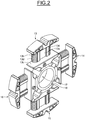
figure 2 illustre une vue de face en perspective d'un dispositif de guidage selon lafigure 1 ; et - La
figure 3 illustre une vue de face d'un dispositif de guidage selon lafigure 1 . - Tel qu'illustré sur la
figure 1 , un rotor de machine électrique, référencée 1 dans son ensemble, comprend un arbre 2 qui s'étend axialement au travers du rotor 1 et un bloc électriquement conducteur 3 qui s'étend radialement à partir de l'arbre 2. - Le bloc électriquement conducteur 3 illustré comprend quatre pôles 4, 5, 6, 7 disposés à un angle, par exemple, de 90° les uns des autres. De préférence, la valeur de l'angle séparant deux pôles est égale à 360 que l'on divise par le nombre de pôles du rotor.
- Chaque pôle 4, 5, 6, 7 comprend deux faces latérales comportant chacune une encoche de réception 4a, 4b, 5a, 5b, 6a, 6b, 7a, 7b d'un ensemble de fils électriquement conducteurs 8, 9, 10, 11. De manière alternative, les quatre pôles 4, 5, 6, 7 peuvent être couplés ensemble ou réalisés dans un même empilement de tôles de manière à former un empilement de tôles en croix.
- Le rotor 1 comprend un dispositif de guidage 12 des fils électriquement conducteurs 8, 9, 10, 11 autour du bloc électriquement conducteur 3 et, notamment autour de chaque pôle 4, 5, 6, 7.
- Comme illustré sur les figures, le dispositif de guidage 12 comprend quatre branches 13, 14, 15, 16 s'étendant radialement en s'écartant de l'arbre 2 du rotor 1 et symétriques par rapport à l'axe du rotor 1. Chaque branche 13, 14, 15, 16 est destinée à être fixée sur un pôle 4, 5, 6, 7 du rotor 1, de sorte que le bobinage de quatre bobines de fils 8, 9, 10, 11 est possible. Le dispositif de guidage 12 présente une forme substantiellement en croix et une partie centrale 17 de passage de l'arbre 2 du rotor 1.
- Tel qu'illustré en détail sur la
figure 2 , et dont uniquement la description de la branche 13 sera détaillée, les autres branches 14, 15, 16 étant identiques à la branche 13, chaque branche 13 comporte une portion principale 13a, destinée à recevoir un ensemble de fils conducteurs 8, et délimitée par deux épaulements 13b, 13c réalisés respectivement à une extrémité de la branche 13 correspondante. Chacun des bords latéraux de la portion principale 13a est disposé en regard d'une encoche 4a, 4b pratiquée sur le bloc conducteur 3, de sorte qu'une portion principale 13a permet à un ensemble de fils 8 de rester positionné entre deux épaulements 13b, 13c d'une branche 13 et dans les encoches de réception 4a, 4b de chaque pôle 4. Chaque fil conducteur 8 est donc bobiné autour de la portion principale 13a du dispositif de guidage 12 entre les deux épaulements 13b, 13c selon une direction parallèle aux épaulements 13b, 13c. Les épaulements 13b, 13c possèdent une épaisseur permettant d'enrouler le fil conducteur 8 sur plusieurs couches autour de la portion principale 13a et permettant de maintenir l'ensemble de fils conducteurs 8 dans l'axe de la portion principale 13a. - La portion principale 13a comprend une pluralité de rainures de guidage 13d pratiquées sur chaque bord latéral de la portion principale 13a et permettant de guider la première couche de bobinage 8 afin d'obtenir une bonne répartition du bobinage des fils conducteurs 8 sur toute la longueur de la portion principale 13a séparant les deux épaulements 13b, 13c d'une branche 13. Chaque bord latéral, et notamment la pluralité de rainures 13d d'une portion principale 13a est aligné avec une encoche 4a, 4b pratiquée sur le bloc conducteur 3, afin de placer correctement les fils conducteurs 8.
- Tel qu'illustré à la
figure 3 , le dispositif de guidage 12 comprend, en outre, un anneau de réception 18 autour duquel sont disposées les branches 13, 14, 15, 16. Chaque branche 13, 14, 15, 16 est reliée indépendamment l'une de l'autre à l'anneau 18 par un moyen de liaison élastique, respectivement 19, 20, 21, 22. Le diamètre de l'anneau 18 est adapté de sorte que l'anneau 18 puisse s'étendre autour de l'arbre 2. - Dans l'exemple illustré, chaque moyen de liaison 19, 20, 21, 22 comprend deux pattes 23, 24, 25, 26, 27, 28, 29, 30 formant un ressort. Chaque patte comprend deux portions adjacentes 23a, 23b, 24a, 24b, 25a, 25b, 26a, 26b, 27a, 27b, 28a, 28b, 29a, 28b, 30a, 30b s'étendant chacune dans un plan, les deux portions formant un angle non nul, autrement dit un angle obtus et un angle aigu. Une première portion 23a, 24a, 25a, 26a, 27a, 28a, 29a, 30a de chaque patte est reliée à une branche 13, 14, 15, 16 et une deuxième portion 23b, 24b, 25b, 26b, 27b, 28b, 29b, 30b est reliée à l'anneau 18. Les deux pattes de chaque moyen de liaison 19, 20, 21, 22 sont disposées de sorte que les deux angles aigus ainsi formés sont en vis-à-vis.
- Bien entendu, dans un mode de réalisation différent, le nombre de pattes de chaque moyen de liaison ainsi que le nombre de portions de chaque patte pourront être supérieurs à deux.
- L'épaisseur d'une patte 23, 24, dans le plan radial du rotor, est inférieure à l'épaisseur, dans ce même plan, de la branche 13 à laquelle est relié le moyen de liaison comprenant ladite patte et, de préférence, inférieure en particulier à la portion principale 13a de la branche 13. De préférence, l'épaisseur de la patte est comprise dans une plage de 40% à 50% de l'épaisseur de la portion principale 13a. Il est ainsi possible de donner l'élasticité souhaitée à la patte.
- En outre, en alternative des pattes, les moyens de liaison élastique 19, 20, 21, 22 pourront comprendre une portion arrondie en forme d'oméga ou toute autre forme adéquate pour le maintien des branches sur l'anneau.
- Un tel dispositif de guidage permet avantageusement de rendre les différentes branches indépendantes en découplant leurs mouvements. En parallèle, le dispositif autorise la déformation axiale et angulaire des branches pour sa mise en oeuvre sur le rotor, tout en assurant la fixation et le maintien d'un bobinage de fils de façon fiable et peu coûteux.
Claims (10)
- Dispositif de guidage (12) pour le bobinage de fils électriquement conducteurs (8, 9) autour d'un bloc électriquement conducteur (3) d'un rotor (1) de moteur électrique comprenant un arbre (2) s'étendant axialement dans le rotor (1), le dispositif (12) comprenant au moins deux branches (13, 14) s'étendant radialement à partir de l'arbre (2), caractérisé en ce qu'il comprend un anneau de réception (18) configuré pour s'étendre autour de l'arbre (2) et autour duquel sont disposées les branches (13, 14), chaque branche (13, 14) étant reliée indépendamment l'une de l'autre à l'anneau (18) par un moyen de liaison élastique (19, 20) comprenant au moins une patte (23, 24, 25, 26), l'épaisseur d'une patte (23, 24) dans le plan radial du rotor étant inférieure à l'épaisseur de la branche (13) à laquelle est relié le moyen de liaison (19) comprenant ladite patte (23, 24).
- Dispositif de guidage selon la revendication 1, caractérisé en ce que chaque branche (13, 14) comprenant des rainures de guidage (13d) destinées à coopérer avec des encoches de réception (4a, 4b, 5a, 5b) prévues sur le bloc électriquement conducteur (3) et destinées à recevoir les fils (8, 9).
- Dispositif de guidage selon la revendication 1, caractérisé en ce que chaque patte (23, 24, 25, 26) comprend au moins deux portions adjacentes (23a, 23b, 24a, 24b, 25a, 25b, 26a, 26b) s'étendant chacune dans un plan, les deux portions (23a, 23b, 24a, 24b, 25a, 25b, 26a, 26b) formant un angle non nul.
- Dispositif de guidage selon la revendication 3, caractérisé en ce que les deux portions adjacentes (23a, 23b, 25a, 25b) d'une première patte (23, 25) forment un angle aigu disposé en vis-à-vis d'un angle aigu formé par les deux portions adjacentes (24a, 24b, 26a, 26b) d'une seconde patte (24, 26).
- Dispositif de guidage selon l'une quelconque des revendications précédentes, caractérisé en ce qu'il est formé en une pièce unique.
- Dispositif de guidage selon la revendication 1, caractérisé en ce que chaque moyen de liaison élastique (19, 20) comprend une portion arrondie en forme d'oméga.
- Dispositif de guidage selon l'une quelconque des revendications précédentes, caractérisé en ce que les branches (13, 14) sont symétriques deux à deux par rapport à l'axe de symétrie du rotor (1).
- Dispositif de guidage selon l'une quelconque des revendications précédentes, caractérisé en ce qu'il comprend quatre branches (13, 14, 15, 16) configurées pour former un moteur électrique à quatre pôles.
- Dispositif de guidage selon l'une quelconque des revendications 1 à 7, caractérisé en ce qu'il comprend huit branches (13, 14, 15, 16) configurées pour former un moteur électrique à huit pôles.
- Rotor de moteur électrique comprenant un arbre (2) s'étendant axialement dans le rotor (1), un bloc électriquement conducteur (3) s'étendant radialement à partir de l'arbre (2) du rotor (1), caractérisé en ce qu'il comprend un dispositif de guidage (12) de fils électriquement conducteurs (8, 9) autour dudit bloc (3) selon l'une quelconque des revendications précédentes.
Applications Claiming Priority (1)
| Application Number | Priority Date | Filing Date | Title |
|---|---|---|---|
| FR1753287A FR3065333B1 (fr) | 2017-04-14 | 2017-04-14 | Dispositif de guidage ameliore d'un ensemble de fils electriques pour rotor de moteur electrique |
Publications (2)
| Publication Number | Publication Date |
|---|---|
| EP3389165A1 true EP3389165A1 (fr) | 2018-10-17 |
| EP3389165B1 EP3389165B1 (fr) | 2020-01-29 |
Family
ID=59253701
Family Applications (1)
| Application Number | Title | Priority Date | Filing Date |
|---|---|---|---|
| EP18163753.9A Active EP3389165B1 (fr) | 2017-04-14 | 2018-03-23 | Dispositif de guidage amélioré d'un ensemble de fils électriques pour rotor de moteur électrique |
Country Status (2)
| Country | Link |
|---|---|
| EP (1) | EP3389165B1 (fr) |
| FR (1) | FR3065333B1 (fr) |
Citations (2)
| Publication number | Priority date | Publication date | Assignee | Title |
|---|---|---|---|---|
| WO2013083407A1 (fr) * | 2011-12-08 | 2013-06-13 | Renault Sas | Dispositif de guidage d'un ensemble de fils electriques pour rotor de moteur electrique |
| WO2013136022A2 (fr) * | 2012-03-16 | 2013-09-19 | Valeo Equipements Electriques Moteur | Ensemble de flasques de rotor de machine electrique tournante comportant des orifices asymetriques favorisant un flux d'air axial a l'interieur du rotor et rotor de machine electrique tournante associe |
-
2017
- 2017-04-14 FR FR1753287A patent/FR3065333B1/fr active Active
-
2018
- 2018-03-23 EP EP18163753.9A patent/EP3389165B1/fr active Active
Patent Citations (2)
| Publication number | Priority date | Publication date | Assignee | Title |
|---|---|---|---|---|
| WO2013083407A1 (fr) * | 2011-12-08 | 2013-06-13 | Renault Sas | Dispositif de guidage d'un ensemble de fils electriques pour rotor de moteur electrique |
| WO2013136022A2 (fr) * | 2012-03-16 | 2013-09-19 | Valeo Equipements Electriques Moteur | Ensemble de flasques de rotor de machine electrique tournante comportant des orifices asymetriques favorisant un flux d'air axial a l'interieur du rotor et rotor de machine electrique tournante associe |
Also Published As
| Publication number | Publication date |
|---|---|
| EP3389165B1 (fr) | 2020-01-29 |
| FR3065333A1 (fr) | 2018-10-19 |
| FR3065333B1 (fr) | 2019-05-03 |
Similar Documents
| Publication | Publication Date | Title |
|---|---|---|
| EP2789076B1 (fr) | Dispositif de guidage d'un ensemble de fils electriques pour rotor de moteur electrique | |
| EP3797468B1 (fr) | Cage pour rotor bobiné de machine electrique synchrone | |
| EP3827500B1 (fr) | Poles asymetriques d'un rotor de machine electrique | |
| EP3057201B1 (fr) | Rotor de moteur électrique et moteur électrique correspondant | |
| EP1251629A1 (fr) | Machine électrique comportant au moins un détecteur de champ magnétique | |
| WO2015155731A2 (fr) | Rotor de machine électrique tournante | |
| FR2982093A1 (fr) | Rotor de machine electrique tournante et machine electrique tournante comprenant un rotor | |
| EP1251623A1 (fr) | Stator de machine tournante électrique comportant des bobines individuelles démontables | |
| EP3142226B1 (fr) | Machine electrique tournante comportant un arbre a diametres etages et procede d'assemblage d'une telle machine | |
| EP1152516B1 (fr) | Machine tournante électrique à rotor à concentration de flux et à stator bobiné sur dents | |
| WO2000038301A1 (fr) | Machine electrique tournante a aimants permanents et a reluctance possedant une construction perfectionnee | |
| EP1251622B1 (fr) | Bobine pour machine électrique tournante | |
| EP3685492B1 (fr) | Isthmes de ponts magnetiques d'un rotor de machine electrique | |
| CH699082B1 (fr) | Moteur électrique avec connecteur. | |
| EP3389165B1 (fr) | Dispositif de guidage amélioré d'un ensemble de fils électriques pour rotor de moteur électrique | |
| FR3051295B1 (fr) | Machine electrique tournante a puissance augmentee | |
| EP3698454A1 (fr) | Machine électrique toroïdale polyphasée | |
| FR3128335A1 (fr) | Dent de bobinage pour stator de machine électrique, outil de préhension d’une telle dent et procédé de fabrication d’un stator de machine électrique. | |
| FR3088150A1 (fr) | Rotor a cage d'ecureuil et machine electrique asynchrone associee | |
| WO2022258545A1 (fr) | Guide de têtes de bobines, rotor bobiné et procédé de bobinage associés | |
| FR3152677A1 (fr) | Machine électrique tournante | |
| EP3576258B1 (fr) | Arbre pour machine électrique tournante, rotor et procédé d'obtention d'un tel rotor | |
| EP0121637B1 (fr) | Embout droit de raccordement électrique | |
| FR2573586A1 (fr) | Perfectionnements aux moteurs a reluctance variable | |
| WO2018100276A1 (fr) | Machine electrique comportant un rotor a aimants permanents interieurs inclines |
Legal Events
| Date | Code | Title | Description |
|---|---|---|---|
| PUAI | Public reference made under article 153(3) epc to a published international application that has entered the european phase |
Free format text: ORIGINAL CODE: 0009012 |
|
| STAA | Information on the status of an ep patent application or granted ep patent |
Free format text: STATUS: THE APPLICATION HAS BEEN PUBLISHED |
|
| AK | Designated contracting states |
Kind code of ref document: A1 Designated state(s): AL AT BE BG CH CY CZ DE DK EE ES FI FR GB GR HR HU IE IS IT LI LT LU LV MC MK MT NL NO PL PT RO RS SE SI SK SM TR |
|
| AX | Request for extension of the european patent |
Extension state: BA ME |
|
| STAA | Information on the status of an ep patent application or granted ep patent |
Free format text: STATUS: REQUEST FOR EXAMINATION WAS MADE |
|
| 17P | Request for examination filed |
Effective date: 20190204 |
|
| RBV | Designated contracting states (corrected) |
Designated state(s): AL AT BE BG CH CY CZ DE DK EE ES FI FR GB GR HR HU IE IS IT LI LT LU LV MC MK MT NL NO PL PT RO RS SE SI SK SM TR |
|
| GRAP | Despatch of communication of intention to grant a patent |
Free format text: ORIGINAL CODE: EPIDOSNIGR1 |
|
| STAA | Information on the status of an ep patent application or granted ep patent |
Free format text: STATUS: GRANT OF PATENT IS INTENDED |
|
| INTG | Intention to grant announced |
Effective date: 20191021 |
|
| GRAS | Grant fee paid |
Free format text: ORIGINAL CODE: EPIDOSNIGR3 |
|
| GRAA | (expected) grant |
Free format text: ORIGINAL CODE: 0009210 |
|
| STAA | Information on the status of an ep patent application or granted ep patent |
Free format text: STATUS: THE PATENT HAS BEEN GRANTED |
|
| AK | Designated contracting states |
Kind code of ref document: B1 Designated state(s): AL AT BE BG CH CY CZ DE DK EE ES FI FR GB GR HR HU IE IS IT LI LT LU LV MC MK MT NL NO PL PT RO RS SE SI SK SM TR |
|
| REG | Reference to a national code |
Ref country code: GB Ref legal event code: FG4D Free format text: NOT ENGLISH |
|
| REG | Reference to a national code |
Ref country code: CH Ref legal event code: EP |
|
| REG | Reference to a national code |
Ref country code: AT Ref legal event code: REF Ref document number: 1229115 Country of ref document: AT Kind code of ref document: T Effective date: 20200215 |
|
| REG | Reference to a national code |
Ref country code: IE Ref legal event code: FG4D Free format text: LANGUAGE OF EP DOCUMENT: FRENCH |
|
| REG | Reference to a national code |
Ref country code: DE Ref legal event code: R096 Ref document number: 602018002173 Country of ref document: DE |
|
| REG | Reference to a national code |
Ref country code: NL Ref legal event code: FP |
|
| REG | Reference to a national code |
Ref country code: NO Ref legal event code: T2 Effective date: 20200129 |
|
| PG25 | Lapsed in a contracting state [announced via postgrant information from national office to epo] |
Ref country code: PT Free format text: LAPSE BECAUSE OF FAILURE TO SUBMIT A TRANSLATION OF THE DESCRIPTION OR TO PAY THE FEE WITHIN THE PRESCRIBED TIME-LIMIT Effective date: 20200621 Ref country code: RS Free format text: LAPSE BECAUSE OF FAILURE TO SUBMIT A TRANSLATION OF THE DESCRIPTION OR TO PAY THE FEE WITHIN THE PRESCRIBED TIME-LIMIT Effective date: 20200129 Ref country code: FI Free format text: LAPSE BECAUSE OF FAILURE TO SUBMIT A TRANSLATION OF THE DESCRIPTION OR TO PAY THE FEE WITHIN THE PRESCRIBED TIME-LIMIT Effective date: 20200129 |
|
| REG | Reference to a national code |
Ref country code: LT Ref legal event code: MG4D |
|
| PG25 | Lapsed in a contracting state [announced via postgrant information from national office to epo] |
Ref country code: BG Free format text: LAPSE BECAUSE OF FAILURE TO SUBMIT A TRANSLATION OF THE DESCRIPTION OR TO PAY THE FEE WITHIN THE PRESCRIBED TIME-LIMIT Effective date: 20200429 Ref country code: IS Free format text: LAPSE BECAUSE OF FAILURE TO SUBMIT A TRANSLATION OF THE DESCRIPTION OR TO PAY THE FEE WITHIN THE PRESCRIBED TIME-LIMIT Effective date: 20200529 Ref country code: SE Free format text: LAPSE BECAUSE OF FAILURE TO SUBMIT A TRANSLATION OF THE DESCRIPTION OR TO PAY THE FEE WITHIN THE PRESCRIBED TIME-LIMIT Effective date: 20200129 Ref country code: LV Free format text: LAPSE BECAUSE OF FAILURE TO SUBMIT A TRANSLATION OF THE DESCRIPTION OR TO PAY THE FEE WITHIN THE PRESCRIBED TIME-LIMIT Effective date: 20200129 Ref country code: GR Free format text: LAPSE BECAUSE OF FAILURE TO SUBMIT A TRANSLATION OF THE DESCRIPTION OR TO PAY THE FEE WITHIN THE PRESCRIBED TIME-LIMIT Effective date: 20200430 Ref country code: HR Free format text: LAPSE BECAUSE OF FAILURE TO SUBMIT A TRANSLATION OF THE DESCRIPTION OR TO PAY THE FEE WITHIN THE PRESCRIBED TIME-LIMIT Effective date: 20200129 |
|
| PG25 | Lapsed in a contracting state [announced via postgrant information from national office to epo] |
Ref country code: MC Free format text: LAPSE BECAUSE OF FAILURE TO SUBMIT A TRANSLATION OF THE DESCRIPTION OR TO PAY THE FEE WITHIN THE PRESCRIBED TIME-LIMIT Effective date: 20200129 Ref country code: ES Free format text: LAPSE BECAUSE OF FAILURE TO SUBMIT A TRANSLATION OF THE DESCRIPTION OR TO PAY THE FEE WITHIN THE PRESCRIBED TIME-LIMIT Effective date: 20200129 Ref country code: SK Free format text: LAPSE BECAUSE OF FAILURE TO SUBMIT A TRANSLATION OF THE DESCRIPTION OR TO PAY THE FEE WITHIN THE PRESCRIBED TIME-LIMIT Effective date: 20200129 Ref country code: SM Free format text: LAPSE BECAUSE OF FAILURE TO SUBMIT A TRANSLATION OF THE DESCRIPTION OR TO PAY THE FEE WITHIN THE PRESCRIBED TIME-LIMIT Effective date: 20200129 Ref country code: LT Free format text: LAPSE BECAUSE OF FAILURE TO SUBMIT A TRANSLATION OF THE DESCRIPTION OR TO PAY THE FEE WITHIN THE PRESCRIBED TIME-LIMIT Effective date: 20200129 Ref country code: CZ Free format text: LAPSE BECAUSE OF FAILURE TO SUBMIT A TRANSLATION OF THE DESCRIPTION OR TO PAY THE FEE WITHIN THE PRESCRIBED TIME-LIMIT Effective date: 20200129 Ref country code: DK Free format text: LAPSE BECAUSE OF FAILURE TO SUBMIT A TRANSLATION OF THE DESCRIPTION OR TO PAY THE FEE WITHIN THE PRESCRIBED TIME-LIMIT Effective date: 20200129 Ref country code: RO Free format text: LAPSE BECAUSE OF FAILURE TO SUBMIT A TRANSLATION OF THE DESCRIPTION OR TO PAY THE FEE WITHIN THE PRESCRIBED TIME-LIMIT Effective date: 20200129 Ref country code: EE Free format text: LAPSE BECAUSE OF FAILURE TO SUBMIT A TRANSLATION OF THE DESCRIPTION OR TO PAY THE FEE WITHIN THE PRESCRIBED TIME-LIMIT Effective date: 20200129 |
|
| REG | Reference to a national code |
Ref country code: DE Ref legal event code: R097 Ref document number: 602018002173 Country of ref document: DE |
|
| REG | Reference to a national code |
Ref country code: AT Ref legal event code: MK05 Ref document number: 1229115 Country of ref document: AT Kind code of ref document: T Effective date: 20200129 |
|
| PLBE | No opposition filed within time limit |
Free format text: ORIGINAL CODE: 0009261 |
|
| STAA | Information on the status of an ep patent application or granted ep patent |
Free format text: STATUS: NO OPPOSITION FILED WITHIN TIME LIMIT |
|
| REG | Reference to a national code |
Ref country code: BE Ref legal event code: MM Effective date: 20200331 |
|
| PG25 | Lapsed in a contracting state [announced via postgrant information from national office to epo] |
Ref country code: LU Free format text: LAPSE BECAUSE OF NON-PAYMENT OF DUE FEES Effective date: 20200323 |
|
| 26N | No opposition filed |
Effective date: 20201030 |
|
| PG25 | Lapsed in a contracting state [announced via postgrant information from national office to epo] |
Ref country code: IT Free format text: LAPSE BECAUSE OF FAILURE TO SUBMIT A TRANSLATION OF THE DESCRIPTION OR TO PAY THE FEE WITHIN THE PRESCRIBED TIME-LIMIT Effective date: 20200129 Ref country code: IE Free format text: LAPSE BECAUSE OF NON-PAYMENT OF DUE FEES Effective date: 20200323 Ref country code: AT Free format text: LAPSE BECAUSE OF FAILURE TO SUBMIT A TRANSLATION OF THE DESCRIPTION OR TO PAY THE FEE WITHIN THE PRESCRIBED TIME-LIMIT Effective date: 20200129 |
|
| PG25 | Lapsed in a contracting state [announced via postgrant information from national office to epo] |
Ref country code: BE Free format text: LAPSE BECAUSE OF NON-PAYMENT OF DUE FEES Effective date: 20200331 Ref country code: PL Free format text: LAPSE BECAUSE OF FAILURE TO SUBMIT A TRANSLATION OF THE DESCRIPTION OR TO PAY THE FEE WITHIN THE PRESCRIBED TIME-LIMIT Effective date: 20200129 Ref country code: SI Free format text: LAPSE BECAUSE OF FAILURE TO SUBMIT A TRANSLATION OF THE DESCRIPTION OR TO PAY THE FEE WITHIN THE PRESCRIBED TIME-LIMIT Effective date: 20200129 |
|
| REG | Reference to a national code |
Ref country code: CH Ref legal event code: PL |
|
| PG25 | Lapsed in a contracting state [announced via postgrant information from national office to epo] |
Ref country code: CH Free format text: LAPSE BECAUSE OF NON-PAYMENT OF DUE FEES Effective date: 20210331 Ref country code: LI Free format text: LAPSE BECAUSE OF NON-PAYMENT OF DUE FEES Effective date: 20210331 |
|
| PG25 | Lapsed in a contracting state [announced via postgrant information from national office to epo] |
Ref country code: TR Free format text: LAPSE BECAUSE OF FAILURE TO SUBMIT A TRANSLATION OF THE DESCRIPTION OR TO PAY THE FEE WITHIN THE PRESCRIBED TIME-LIMIT Effective date: 20200129 Ref country code: MT Free format text: LAPSE BECAUSE OF FAILURE TO SUBMIT A TRANSLATION OF THE DESCRIPTION OR TO PAY THE FEE WITHIN THE PRESCRIBED TIME-LIMIT Effective date: 20200129 Ref country code: CY Free format text: LAPSE BECAUSE OF FAILURE TO SUBMIT A TRANSLATION OF THE DESCRIPTION OR TO PAY THE FEE WITHIN THE PRESCRIBED TIME-LIMIT Effective date: 20200129 |
|
| PG25 | Lapsed in a contracting state [announced via postgrant information from national office to epo] |
Ref country code: MK Free format text: LAPSE BECAUSE OF FAILURE TO SUBMIT A TRANSLATION OF THE DESCRIPTION OR TO PAY THE FEE WITHIN THE PRESCRIBED TIME-LIMIT Effective date: 20200129 Ref country code: AL Free format text: LAPSE BECAUSE OF FAILURE TO SUBMIT A TRANSLATION OF THE DESCRIPTION OR TO PAY THE FEE WITHIN THE PRESCRIBED TIME-LIMIT Effective date: 20200129 |
|
| P01 | Opt-out of the competence of the unified patent court (upc) registered |
Effective date: 20230608 |
|
| REG | Reference to a national code |
Ref country code: DE Ref legal event code: R081 Ref document number: 602018002173 Country of ref document: DE Owner name: AMPERE S.A.S., FR Free format text: FORMER OWNER: RENAULT S.A.S., BOULOGNE-BILLANCOURT, FR |
|
| REG | Reference to a national code |
Ref country code: NL Ref legal event code: PD Owner name: AMPERE S.A.S.; FR Free format text: DETAILS ASSIGNMENT: CHANGE OF OWNER(S), ASSIGNMENT; FORMER OWNER NAME: RENAULT S.A.S. Effective date: 20250402 |
|
| REG | Reference to a national code |
Ref country code: GB Ref legal event code: 732E Free format text: REGISTERED BETWEEN 20250501 AND 20250507 |
|
| PGFP | Annual fee paid to national office [announced via postgrant information from national office to epo] |
Ref country code: GB Payment date: 20260324 Year of fee payment: 9 |
|
| PGFP | Annual fee paid to national office [announced via postgrant information from national office to epo] |
Ref country code: NO Payment date: 20260323 Year of fee payment: 9 Ref country code: DE Payment date: 20260319 Year of fee payment: 9 |
|
| PGFP | Annual fee paid to national office [announced via postgrant information from national office to epo] |
Ref country code: NL Payment date: 20260319 Year of fee payment: 9 |
|
| PGFP | Annual fee paid to national office [announced via postgrant information from national office to epo] |
Ref country code: FR Payment date: 20260320 Year of fee payment: 9 |