EP3389055A1 - X-ray device for generating high-energy x-ray radiation - Google Patents
X-ray device for generating high-energy x-ray radiation Download PDFInfo
- Publication number
- EP3389055A1 EP3389055A1 EP17165888.3A EP17165888A EP3389055A1 EP 3389055 A1 EP3389055 A1 EP 3389055A1 EP 17165888 A EP17165888 A EP 17165888A EP 3389055 A1 EP3389055 A1 EP 3389055A1
- Authority
- EP
- European Patent Office
- Prior art keywords
- electron beam
- target
- ray
- diaphragm
- ray device
- Prior art date
- Legal status (The legal status is an assumption and is not a legal conclusion. Google has not performed a legal analysis and makes no representation as to the accuracy of the status listed.)
- Pending
Links
- 230000005855 radiation Effects 0.000 title claims abstract description 19
- 238000010894 electron beam technology Methods 0.000 claims abstract description 49
- 239000000463 material Substances 0.000 claims abstract description 32
- 238000001816 cooling Methods 0.000 claims description 11
- 239000007787 solid Substances 0.000 claims description 9
- 238000010521 absorption reaction Methods 0.000 claims description 6
- 238000004519 manufacturing process Methods 0.000 claims description 4
- 229910052751 metal Inorganic materials 0.000 claims description 4
- 239000002184 metal Substances 0.000 claims description 4
- XLYOFNOQVPJJNP-UHFFFAOYSA-N water Substances O XLYOFNOQVPJJNP-UHFFFAOYSA-N 0.000 claims description 4
- OKTJSMMVPCPJKN-UHFFFAOYSA-N Carbon Chemical compound [C] OKTJSMMVPCPJKN-UHFFFAOYSA-N 0.000 claims description 3
- RYGMFSIKBFXOCR-UHFFFAOYSA-N Copper Chemical compound [Cu] RYGMFSIKBFXOCR-UHFFFAOYSA-N 0.000 claims description 3
- RTAQQCXQSZGOHL-UHFFFAOYSA-N Titanium Chemical compound [Ti] RTAQQCXQSZGOHL-UHFFFAOYSA-N 0.000 claims description 3
- 229910052802 copper Inorganic materials 0.000 claims description 3
- 239000010949 copper Substances 0.000 claims description 3
- 229910002804 graphite Inorganic materials 0.000 claims description 3
- 239000010439 graphite Substances 0.000 claims description 3
- 239000010935 stainless steel Substances 0.000 claims description 3
- 229910001220 stainless steel Inorganic materials 0.000 claims description 3
- 239000010936 titanium Substances 0.000 claims description 3
- 229910052719 titanium Inorganic materials 0.000 claims description 3
- 238000000034 method Methods 0.000 description 6
- 239000011888 foil Substances 0.000 description 5
- 238000001959 radiotherapy Methods 0.000 description 5
- 230000001133 acceleration Effects 0.000 description 4
- 238000001803 electron scattering Methods 0.000 description 4
- 239000013077 target material Substances 0.000 description 4
- 238000013459 approach Methods 0.000 description 3
- 238000013461 design Methods 0.000 description 3
- 230000003993 interaction Effects 0.000 description 3
- 230000001902 propagating effect Effects 0.000 description 3
- 229910052723 transition metal Inorganic materials 0.000 description 3
- 150000003624 transition metals Chemical class 0.000 description 3
- 229910045601 alloy Inorganic materials 0.000 description 2
- 239000000956 alloy Substances 0.000 description 2
- 239000012809 cooling fluid Substances 0.000 description 2
- 238000011161 development Methods 0.000 description 2
- 238000009826 distribution Methods 0.000 description 2
- 239000012530 fluid Substances 0.000 description 2
- 238000003384 imaging method Methods 0.000 description 2
- 230000002093 peripheral effect Effects 0.000 description 2
- 238000012546 transfer Methods 0.000 description 2
- 229910000831 Steel Inorganic materials 0.000 description 1
- 230000005540 biological transmission Effects 0.000 description 1
- 238000006243 chemical reaction Methods 0.000 description 1
- 238000002591 computed tomography Methods 0.000 description 1
- 238000010276 construction Methods 0.000 description 1
- 230000007423 decrease Effects 0.000 description 1
- 230000001419 dependent effect Effects 0.000 description 1
- 238000002059 diagnostic imaging Methods 0.000 description 1
- 239000003814 drug Substances 0.000 description 1
- 230000000694 effects Effects 0.000 description 1
- 238000003780 insertion Methods 0.000 description 1
- 230000037431 insertion Effects 0.000 description 1
- 238000007689 inspection Methods 0.000 description 1
- 238000002721 intensity-modulated radiation therapy Methods 0.000 description 1
- 239000007769 metal material Substances 0.000 description 1
- 238000009659 non-destructive testing Methods 0.000 description 1
- 230000003287 optical effect Effects 0.000 description 1
- 239000002245 particle Substances 0.000 description 1
- 239000010959 steel Substances 0.000 description 1
- WFKWXMTUELFFGS-UHFFFAOYSA-N tungsten Chemical compound [W] WFKWXMTUELFFGS-UHFFFAOYSA-N 0.000 description 1
- 229910052721 tungsten Inorganic materials 0.000 description 1
- 239000010937 tungsten Substances 0.000 description 1
- 239000013585 weight reducing agent Substances 0.000 description 1
Images

Classifications
-
- H—ELECTRICITY
- H05—ELECTRIC TECHNIQUES NOT OTHERWISE PROVIDED FOR
- H05G—X-RAY TECHNIQUE
- H05G1/00—X-ray apparatus involving X-ray tubes; Circuits therefor
- H05G1/08—Electrical details
- H05G1/26—Measuring, controlling or protecting
- H05G1/30—Controlling
- H05G1/52—Target size or shape; Direction of electron beam, e.g. in tubes with one anode and more than one cathode
-
- H—ELECTRICITY
- H01—ELECTRIC ELEMENTS
- H01J—ELECTRIC DISCHARGE TUBES OR DISCHARGE LAMPS
- H01J35/00—X-ray tubes
- H01J35/02—Details
- H01J35/16—Vessels; Containers; Shields associated therewith
-
- G—PHYSICS
- G21—NUCLEAR PHYSICS; NUCLEAR ENGINEERING
- G21K—TECHNIQUES FOR HANDLING PARTICLES OR IONISING RADIATION NOT OTHERWISE PROVIDED FOR; IRRADIATION DEVICES; GAMMA RAY OR X-RAY MICROSCOPES
- G21K1/00—Arrangements for handling particles or ionising radiation, e.g. focusing or moderating
- G21K1/02—Arrangements for handling particles or ionising radiation, e.g. focusing or moderating using diaphragms, collimators
-
- H—ELECTRICITY
- H01—ELECTRIC ELEMENTS
- H01J—ELECTRIC DISCHARGE TUBES OR DISCHARGE LAMPS
- H01J35/00—X-ray tubes
-
- H—ELECTRICITY
- H05—ELECTRIC TECHNIQUES NOT OTHERWISE PROVIDED FOR
- H05H—PLASMA TECHNIQUE; PRODUCTION OF ACCELERATED ELECTRICALLY-CHARGED PARTICLES OR OF NEUTRONS; PRODUCTION OR ACCELERATION OF NEUTRAL MOLECULAR OR ATOMIC BEAMS
- H05H6/00—Targets for producing nuclear reactions
-
- G—PHYSICS
- G21—NUCLEAR PHYSICS; NUCLEAR ENGINEERING
- G21K—TECHNIQUES FOR HANDLING PARTICLES OR IONISING RADIATION NOT OTHERWISE PROVIDED FOR; IRRADIATION DEVICES; GAMMA RAY OR X-RAY MICROSCOPES
- G21K1/00—Arrangements for handling particles or ionising radiation, e.g. focusing or moderating
- G21K1/10—Scattering devices; Absorbing devices; Ionising radiation filters
-
- H—ELECTRICITY
- H01—ELECTRIC ELEMENTS
- H01J—ELECTRIC DISCHARGE TUBES OR DISCHARGE LAMPS
- H01J2235/00—X-ray tubes
- H01J2235/08—Targets (anodes) and X-ray converters
-
- H—ELECTRICITY
- H01—ELECTRIC ELEMENTS
- H01J—ELECTRIC DISCHARGE TUBES OR DISCHARGE LAMPS
- H01J2235/00—X-ray tubes
- H01J2235/12—Cooling
- H01J2235/1225—Cooling characterised by method
- H01J2235/1262—Circulating fluids
-
- H—ELECTRICITY
- H05—ELECTRIC TECHNIQUES NOT OTHERWISE PROVIDED FOR
- H05H—PLASMA TECHNIQUE; PRODUCTION OF ACCELERATED ELECTRICALLY-CHARGED PARTICLES OR OF NEUTRONS; PRODUCTION OR ACCELERATION OF NEUTRAL MOLECULAR OR ATOMIC BEAMS
- H05H9/00—Linear accelerators
- H05H9/04—Standing-wave linear accelerators
- H05H9/048—Lepton LINACS
Definitions
- the invention relates to an X-ray device for generating high-energy X-ray radiation, comprising a linear accelerator and a target.
- the linear accelerator is designed to generate X-radiation to produce an electron beam directed at the target, whose kinetic energy per electron is at least 1 MeV.
- X-ray devices typically include an electron beam source that provides an accelerated electron beam for impinging a target (also: target material). When the electrons strike the target, X-rays are generated in the area of the so-called focal spot.
- the electron beam source is usually formed by a cathode, wherein the exiting electrodes are accelerated by an applied acceleration field strength in the direction of an anode, which forms the target in such embodiments.
- a linear accelerator as the electron beam source, which provides an electron beam directed at the target.
- the electron beam passes through an aperture channel delimiting it laterally, which is introduced in a diaphragm body.
- an aperture channel delimiting it laterally, which is introduced in a diaphragm body.
- the area around the aperture channel must be made as solid as possible, if appropriate, water cooling is additionally provided.
- an object of the present invention is to provide an X-ray device for generating high-energy X-radiation, in which the extent of the focal spot on the target can be minimized.
- An X-ray device for generating high-energy X-ray radiation comprises a linear accelerator and a target.
- the target typically consists of a target material which serves to generate X-radiation by decelerating the accelerated electrons.
- the area of the target in which this conversion takes place is called the focal spot.
- the linear accelerator is further adapted and adapted to generate an electron beam directed at the target, the kinetic energy of which per electron is at least 1 MeV.
- a diaphragm is arranged in the beam path of the electron beam between the linear accelerator and the target, which diaphragm has an edge region surrounding an aperture, whose material thickness in the propagation direction of the electron beam is less than 10% of the mean range of electrons of the kinetic energy generated in the material of the edge region.
- the invention chooses to limit the focal spot in this energetic region by the approach of providing a stop which is not designed to absorb the electrons of the generated energy range to a considerable extent, but rather that the interaction is essentially limited to inelastic or elastic scattering processes shall be.
- the diaphragm has a material thickness which is only a fraction of the average range of electrons of the kinetic energy generated in the material of the edge region.
- the peripheral electrons which penetrate the edge region undergo a deflection and are scattered.
- the subsequently divergently propagating electrons then generally no longer strike the target material forming the target.
- the focal spot generating region of the electron beam is thus limited to substantially the area of the aperture.
- the energy transfer to the diaphragm is minimal, since it is based essentially only on inelastic scattering effects. This requires inter alia a lower heat input to the panel, which therefore does not necessarily have to be additionally cooled.
- the edge region of the diaphragm forms a scattering body (also: diffuser) for the electrons passing through the energy range predetermined by the applied acceleration voltage.
- the case deflected randomly Electrons can be absorbed in other regions of the X-ray device and are therefore no longer visible in the useful radiation field of the X-radiation generated.
- the limitation of the extent of the focal spot on the target requires inter alia an improved image quality in imaging processes.
- the captured images have a lower blur or smaller penumbra, as the extent of the focal spot approaches an ideal point source.
- Possible fields of application relate, for example, to radioscopy, in particular the non-destructive testing of workpieces, components or other objects, the checking of goods in transit, in particular as part of a freight inspection in which, for example, trucks or freight containers for trains or container ships are illuminated to make their content visible or Applications in the field of medicine, in particular in the field of radiotherapy.
- a more precise dose distribution can be realized in radiation therapy, in particular in the case of intensity-modulated radiation therapy, since the partial shadows of the collimator delimiting the photon radiation field are smaller.
- the X-ray devices can be optimized in terms of their weight, since downstream collimators for collimating the generated X-ray radiation can be omitted or at least limited.
- the diaphragm consists in a simple embodiment of a thin sheet, in particular steel or other transition metal or alloy.
- Another particularly preferred non-metallic material for the panel is graphite, for example.
- the material and the material thickness of the diaphragm, at least in the edge region surrounding the diaphragm opening, are based on the kinetic energy of the electrons generated during the intended use of the X-ray device is tuned.
- the material thickness is typically in the range of one or more millimeters if it is made of a light material such as graphite. Apertures made of a heavier material, in particular metal, have lower material thicknesses, for example in the submillimeter range, in particular in the range of approximately 1/10 mm.
- At least the electron-scattering edge region of the diaphragm is formed by one or more foils.
- Such embodiments are to be regarded as cost-effective implementations of a scatterer of small thickness, in which it is ensured that the interaction with the electrons of the kinetic energy generated is essentially limited to scattering processes. If the region of the diaphragm which is the cause of the scattering of the electrons is formed by such a film material, then the heat input is minimal.
- the apertures formed in this way therefore do not necessarily have to be actively cooled during the operation of the X-ray device.
- the film is preferably made of a metal.
- the diaphragm or at least the scattering edge region of the diaphragm consists of titanium.
- the diaphragm or at least the edge region surrounding the diaphragm opening consists of stainless steel, tungsten or copper or of another transition metal or transition metal alloy.
- the diaphragm in particular the diaphragm described above consisting of at least one metallic foil, can be cooled in one possible embodiment by means of a cooling device, in particular by means of a water cooling device. This ensures that even the relatively low heat transfer transmitted by inelastic scattering processes can be dissipated reliably.
- a collimator is arranged in the beam path of the X-rays generated by the application of the target. This serves to limit the useful radiation field of the generated X-radiation. If the location of the X-ray generation (focal spot) is small, the half-shadows at the boundaries of the useful-beam field are also small.
- a vacuum housing surrounding at least the linear accelerator, the diaphragm and the target, or a vacuum envelope surrounding these components is provided at least in regions with a shield which is suitable for absorbing x-radiation caused by scattered electrons which impinge on the vacuum housing and be slowed down.
- the resulting X-ray radiation can be spectrally influenced by the choice of the wall material and is preferably shielded locally by a shield arranged outside the vacuum housing.
- the shield is provided inside the vacuum housing. Since the vacuum housing of the X-ray device is evacuated, the shield provided in the interior of the vacuum housing preferably consists of a material with a high vapor pressure, particularly preferably the shield comprises elements with a low atomic number.
- This shield consists for example wholly or partly of lead. Since the scattered electrons are not absorbed by the material of the diaphragm, they spread divergently to the propagation direction of the electron beam and impinge on the shielded vacuum housing from which they are absorbed. Since the absorption of the scattered at the aperture electrons in a highly localized area, but in large areas of the vacuum housing, also here can generally be dispensed with an external cooling.
- the vacuum housing of the X-ray device can be cooled by means of fluid cooling.
- the areas provided with the shielding regions of the vacuum housing without shielding have an increased absorption for electrons of the kinetic energy generated.
- it is intended to shield only those regions which are relevant for the absorption of scattered electrons. This contributes among other things to the weight reduction.
- the regions provided with the shield preferably lie exclusively within a solid angle range extending from the diaphragm and extending in the propagation direction of the electron beam.
- the solid angle region is preferably formed by a multiplicity of superimposed scattering cones whose conical tips lie within the edge region surrounding the aperture.
- the shield is arranged where the electrons scattered in the edge region of the diaphragm impinge, at least with high probability.
- the solid angle region to be shielded corresponds to a mean scattering angle range of the electrons scattered in the edge region of the diaphragm.
- the deflection of the scattered electrons with respect to the propagation direction of the non-scattered electrons at higher energies is smaller than with electrons of lower kinetic energy.
- the shield can therefore be limited to a smaller solid angle range concentrated around the propagation direction of the non-scattered electron beam.
- a mean scattering angle range is assumed to be a scattering cone centered around the mean scattering angle, whose opening angle corresponds to a mean deviation, in particular a standard deviation, characteristic of the scattering process.
- the mean scattering angle denotes the mean value of the angles of the scattered electrons to the acceleration axis, which coincides with the propagation direction of the unscattered electrons.
- the linear accelerator of the X-ray device is preferably designed to generate an electron beam whose kinetic energy per electron is less than 20 MeV.
- the X-ray device is thus preferably used for the applications already described in the field of radioscopy or radiology.
- the invention further relates to a method for producing an X-ray device for generating high-energy X-radiation, in particular a method for producing one of the X-ray devices described above.
- the X-ray device comprises a linear accelerator and a target, wherein the linear accelerator for generating X-ray radiation is adapted to generate an electron beam directed onto the target, the kinetic energy of which Energy per electron is at least 1MeV.
- a component is arranged in the beam path of the electron beam between the linear accelerator and the target whose material thickness in the propagation direction of the electron beam is less than 10% of the mean range of electrons of the kinetic energy generated in the material of the component.
- an aperture is introduced by the fact that the component is acted upon by an electron beam generated by the linear accelerator. In this sense, the component after insertion of the aperture forms the aperture already described.
- the electron beams generated by means of linear accelerators are already strongly focused due to the applied electrical spring, so that the particle density in the center of the electron beam is greatly increased.
- This feature makes use of the invention to introduce the aperture described above in the component.
- the current intensity of the accelerated electron beam provided by the linear accelerator is increased relative to the current intensity generated during normal operation in order to burn a hole in the component introduced in the beam path, which is formed, for example, by one or more of the foils described above.
- the dimensioning of the diaphragm opening thus produced corresponds to the central region of the electron beam and thus automatically corresponds to an aperture with the above-described scattering characteristic for the electrons propagating away from the central region. A complex adjustment of an aperture already having a diaphragm can be avoided and thus assembly and adjustment costs can be saved.
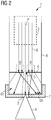
- FIG. 1 shows an X-ray device 1 according to a first embodiment of the invention in a schematic sectional view.
- the X-ray device 1 comprises a linear accelerator 2 shown only schematically, which is designed to generate an electron beam E of the kinetic energy of at least 1 MeV per electron.
- the electron beam E is directed to a target 3.
- the target 3 emits X-rays R. in the region of a focal spot.
- a diaphragm 4 In the beam path between the linear accelerator 2 and the target 3, a diaphragm 4 is arranged, which diffuses a peripheral part of the incident primary electron beam E diffusely, so that the extension of the focal spot on the target 3 is reduced.
- at least one edge region B of the diaphragm 4 surrounding a diaphragm opening 5 consists of a material which is suitable for scattering electrons of the kinetic energy generated.
- the edge region B of the diaphragm 4 has a material thickness in the propagation direction P of the electron beam E, which is small in comparison to the range of the electrons of the kinetic energy generated in the material of the edge region B.
- the material thickness of the edge region B in the embodiment considered here is less than about 10% of the range of electrons with the kinetic energy of 1 MeV in the material of the edge region B.
- the electrons propagating away from the center of the electron beam E are diffused by the edge region B and thus distributed over the inner surface of a vacuum housing 6 of the X-ray device 1 over a large area. Accordingly, the heat input caused by the absorption of these electrons is also distributed over wide areas of the vacuum housing 6, so that external cooling of the vacuum housing 6 can be dispensed with.
- a shield 7 is arranged, which consists in the exemplary embodiment of lead and extends - with the exception of the area of the target 3 - over the entire outer surface of the vacuum housing 6.
- the panel 4 is formed in the embodiment shown from a simple sheet or foil made of metal. Since the interaction of the electrons with the material of the diaphragm 4 is essentially limited to inelastic and elastic scattering events, the heat input is also minimal here. A cooling of the aperture 4 is therefore not mandatory.
- a cooling device 8 is provided for fluid cooling of the diaphragm 4, which is shown schematically in FIG FIG. 1 is shown.
- the aperture 4 is designed such that a cooling fluid, for example water, at least through a portion of the aperture can be passed through.
- the diaphragm 4 is formed by two plane-parallel foils, between which a gap is formed into which the cooling fluid can be introduced.
- the proportion of the X radiation R caused by scattered electrons can be further reduced if a collimation of the X radiation R emanating from the target 3 takes place.
- a collimator 9 for example a lamellar collimator, is optionally arranged in the region of the exiting X-radiation R that is close to the target.
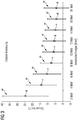
- FIG. 2 shows an X-ray device 1 according to a second embodiment.
- the second embodiment differs from that in FIG. 1 illustrated embodiment only with respect to the extent of the shield 7, so that reference is first made to the relevant description in order to avoid repetition.
- the shield 7 is limited to a portion of the vacuum housing 6.
- the design of the shield 7 is such that at least the majority of the scattered in the edge region B electrons are absorbed by the shield 7.
- a solid angle range ⁇ emanating from the scattering edge region B into which at least the vast majority of electrons are scattered on average is shielded.
- the extent of the shielding 7 is thus interpreted as a function of the kinetic energy of the electrons in accordance with the average scattering angle ⁇ and the mean deviation from this mean scattering angle ⁇ .
- the relevant for the design of the shield 7 information is in FIG. 3 illustrated for a selected litter material and for certain energy ranges between 2MeV and 18MeV. Shown are each for electron scattering of the respective Energy relevant average scattering angle ⁇ and the mean deviation ⁇ thereof, which is shown as centered around the mean scattering angle ⁇ bar.
- the mean deviation ⁇ here corresponds to the standard deviation, so that in the example illustrated here, assuming normally distributed scattering events, it can be assumed that approximately 68% of the average scattering angle range defined by the mean scattering angle ⁇ and the mean deviation ⁇ is scattered.
- the knowledge of the average scattering angle ranges as a function of the kinetic energy of the incident electrons can be used to specifically design and shield the X-ray device 1 geometrically.
- the solid angle range ⁇ , which the shielding 7 covers, corresponds to the sum of the average scattering angle ranges whose scattering centers lie in the edge region B of the diaphragm 4 which is decisive for the electron scattering.
- the extent of the shield 7 can be significantly reduced by this construction.
- a preferred method for producing the above-described X-ray device 1 comprises a method step in which a component which forms the diaphragm 4 in the final assembled state is introduced into the beam path of the electron beam E provided by the linear accelerator 2.
- the aperture 5 is burned into the component by means of the electron beam E.
- the current intensity of the electron beam provided by the linear accelerator 2 can be increased with respect to the current intensity generated during regular operation. Since the number of electrons is greatly increased due to the focusing properties of the linear accelerator 2 in a central region of the electron beam E and decreases sharply at the edge, such an approach leaves an edge region B surrounding the aperture 5 with the above-described scattering properties.
- Edge-side beam areas of the electron beam E in which the number of electrons in comparison is greatly reduced to the central region of the electron beam E, thus scattered in the regular operation of the X-ray device 1 from the target 3 and so minimizes the expansion of the focal spot on the target 3.
Landscapes
- Physics & Mathematics (AREA)
- Engineering & Computer Science (AREA)
- Spectroscopy & Molecular Physics (AREA)
- High Energy & Nuclear Physics (AREA)
- Plasma & Fusion (AREA)
- Optics & Photonics (AREA)
- Chemical Kinetics & Catalysis (AREA)
- Chemical & Material Sciences (AREA)
- General Engineering & Computer Science (AREA)
- Health & Medical Sciences (AREA)
- General Health & Medical Sciences (AREA)
- Toxicology (AREA)
- Radiation-Therapy Devices (AREA)
- X-Ray Techniques (AREA)
- Particle Accelerators (AREA)
Abstract
Eine Röntgeneinrichtung (1) zur Erzeugung von hochenergetischer Röntgenstrahlung umfasst einen Linearbeschleuniger (2) und ein Target (3). Der Linearbeschleuniger (2) ist zur Erzeugung von Röntgenstrahlung (R) dazu ausgebildet, einen auf das Target (3) gerichteten Elektronenstrahl (E) zu erzeugen, dessen kinetische Energie pro Elektron zumindest 1MeV beträgt. Gemäß der Erfindung ist eine Blende (4) im Strahlengang des Elektronenstrahls (E) zwischen Linearbeschleuniger (2) und Target (3) angeordnet, welche einen eine Blendenöffnung (5) umgebenden Randbereich (B) aufweist, dessen Materialstärke in Propagationsrichtung (P) des Elektronenstrahls (E) weniger als 10% der mittleren Reichweite von Elektronen der erzeugten kinetischen Energie im Material des Randbereichs (B) beträgt.An X-ray device (1) for generating high-energy X-ray radiation comprises a linear accelerator (2) and a target (3). The linear accelerator (2) is designed to generate X-ray radiation (R) to produce an electron beam (E) directed onto the target (3) whose kinetic energy per electron is at least 1 MeV. According to the invention, a diaphragm (4) is arranged in the beam path of the electron beam (E) between linear accelerator (2) and target (3), which has an edge region (B) surrounding a diaphragm opening (5) whose material thickness in the propagation direction (P) of the Electron beam (E) is less than 10% of the mean range of electrons of the kinetic energy generated in the material of the edge region (B).
Description
Die Erfindung betrifft eine Röntgeneinrichtung zur Erzeugung von hochenergetischer Röntgenstrahlung, umfassend einen Linearbeschleuniger und ein Target. Der Linearbeschleuniger ist zur Erzeugung von Röntgenstrahlung dazu ausgebildet, einen auf das Target gerichteten Elektronenstrahl zu erzeugen, dessen kinetische Energie pro Elektron zumindest 1MeV beträgt.The invention relates to an X-ray device for generating high-energy X-ray radiation, comprising a linear accelerator and a target. The linear accelerator is designed to generate X-radiation to produce an electron beam directed at the target, whose kinetic energy per electron is at least 1 MeV.
Röntgeneinrichtungen weisen typischerweise eine Elektronenstrahlquelle auf, die einen beschleunigten Elektronenstrahl zur Beaufschlagung eines Targets (auch: Zielmaterial) bereitstellen. Beim Auftreffen der Elektronen auf das Target entsteht im Bereich des sogenannten Brennflecks Röntgenstrahlung. Die Elektronenstrahlquelle wird für gewöhnlich von einer Kathode gebildet, wobei die austretenden Elektroden durch eine anliegenden Beschleunigungsfeldstärke in Richtung einer Anode, welche in derartigen Ausführungen das Target bildet, beschleunigt werden. Bei Hochenergieanwendungen ist es ferner bekannt, einen Linearbeschleuniger als Elektronenstrahlquelle einzusetzen, der einen auf das Target gerichteten Elektronenstrahl bereitstellt.X-ray devices typically include an electron beam source that provides an accelerated electron beam for impinging a target (also: target material). When the electrons strike the target, X-rays are generated in the area of the so-called focal spot. The electron beam source is usually formed by a cathode, wherein the exiting electrodes are accelerated by an applied acceleration field strength in the direction of an anode, which forms the target in such embodiments. In high-energy applications, it is also known to use a linear accelerator as the electron beam source, which provides an electron beam directed at the target.
In vielen Anwendungen der Radioskopie oder Radiologie besteht das Bedürfnis, einen möglichst kleinen Brennfleck zu erzeugen. Bei der Bildgebung kann dadurch beispielsweise eine hohe Ortsauflösung bei optischer Vergrößerung erreicht werden oder die von den das Röntgenstrahlenfeld begrenzenden Blenden verursachten Halbschatten verkleinert werden. Bei der Strahlentherapie, insbesondere bei der intensitätsmodulierten Strahlentherapie, kann so weiterhin eine präzisere Dosisverteilung der deponierten Röntgenstrahlung realisiert werden.
Aus
Out
Ausgehend von diesem Stand der Technik ist Aufgabe der vorliegenden Erfindung, eine Röntgeneinrichtung zur Erzeugung von hochenergetischer Röntgenstrahlung anzugeben, bei der die Ausdehnung des Brennflecks auf dem Target minimiert werden kann.Based on this prior art, an object of the present invention is to provide an X-ray device for generating high-energy X-radiation, in which the extent of the focal spot on the target can be minimized.
Gemäß der Erfindung wird diese Aufgabe gelöst durch eine Röntgeneinrichtung zur Erzeugung von hochenergetischer Röntgenstrahlung der eingangs genannten Art mit den kennzeichnenden Merkmalen des Patenanspruchs 1.According to the invention, this object is achieved by an X-ray device for generating high-energy X-ray radiation of the type mentioned above with the characterizing features of patent claim 1.
Vorteilhafte Ausgestaltungen der Erfindung sind Gegenstand der Unteransprüche.Advantageous embodiments of the invention are the subject of the dependent claims.
Eine Röntgeneinrichtung zur Erzeugung von hochenergetischer Röntgenstrahlung umfasst einen Linearbeschleuniger und ein Target. Das Target besteht typischerweise aus einem Zielmaterial, welches zur Erzeugung von Röntgenstrahlung durch Abbremsung der beschleunigten Elektronen dient. Der Bereich des Targets, in dem diese Konvertierung stattfindet, wird als Brennfleck bezeichnet. Der Linearbeschleuniger ist weiterhin dazu ausgebildet und ausgerichtet, einen auf das Target gerichteten Elektronenstrahl zu erzeugen, dessen kinetische Energie pro Elektron zumindest 1MeV beträgt. Gemäß der Erfindung ist im Strahlengang des Elektronenstrahls zwischen dem Linearbeschleuniger und dem Target eine Blende angeordnet, welche einen eine Blendenöffnung umgebenden Randbereich aufweist, dessen Materialstärke in Propagationsrichtung des Elektronenstrahls weniger als 10% der mittleren Reichweite von Elektronen der erzeugten kinetischen Energie im Material des Randbereichs beträgt.An X-ray device for generating high-energy X-ray radiation comprises a linear accelerator and a target. The target typically consists of a target material which serves to generate X-radiation by decelerating the accelerated electrons. The area of the target in which this conversion takes place is called the focal spot. The linear accelerator is further adapted and adapted to generate an electron beam directed at the target, the kinetic energy of which per electron is at least 1 MeV. According to the invention, a diaphragm is arranged in the beam path of the electron beam between the linear accelerator and the target, which diaphragm has an edge region surrounding an aperture, whose material thickness in the propagation direction of the electron beam is less than 10% of the mean range of electrons of the kinetic energy generated in the material of the edge region.
In Linearbeschleunigern werden typischerweise hohe kinetische Energien erreicht, so dass die emittierten Elektronen eine im Vergleich zu den in herkömmlichen Röntgenröhren erzeugten Elektronen erhöhte mittlere Reichweite in Materialien haben. Die Erfindung wählt zur Begrenzung des Brennflecks in diesem energetischen Bereich den Ansatz, eine Blende vorzusehen, die nicht dazu ausgebildet ist, die Elektronen des erzeugten Energiebereichs in merklichem Ausmaß zu absorbieren, vielmehr ist vorgesehen, dass die Wechselwirkung im Wesentlichen auf inelastische oder elastische Streuvorgänge beschränkt werden soll. Hierzu weist die Blende zumindest in dem die Blendenöffnung begrenzenden Randbereich eine Materialstärke auf, die lediglich ein Bruchteil der mittleren Reichweite von Elektronen der erzeugten kinetischen Energie im Material der Randbereichs beträgt. Bei der Transmission des Elektronenstrahls durch den Randbereich der Blende erfahren die peripheren Elektronen, welche den Randbereich durchdringen, eine Auslenkung und werden gestreut. Die daraufhin divergent propagierenden Elektronen treffen anschießend im Allgemeinen nicht mehr auf das Zielmaterial auf, welches das Target bildet. Der den Brennfleck erzeugende Bereich des Elektronenstrahls ist somit im Wesentlichen auf den Bereich der Blendenöffnung begrenzt. Gleichzeitig ist der Energieübertrag auf die Blende minimal, da dieser im Wesentlichen nur auf inelastische Streueffekte beruht. Dies bedingt unter anderem einen geringeren Wärmeeintrag auf die Blende, die daher nicht notwendigerweise zusätzlich gekühlt werden muss.In linear accelerators, high kinetic energies are typically achieved so that the emitted electrons have an increased average range in materials as compared to the electrons generated in conventional x-ray tubes. The invention chooses to limit the focal spot in this energetic region by the approach of providing a stop which is not designed to absorb the electrons of the generated energy range to a considerable extent, but rather that the interaction is essentially limited to inelastic or elastic scattering processes shall be. For this purpose, at least in the edge region delimiting the diaphragm opening, the diaphragm has a material thickness which is only a fraction of the average range of electrons of the kinetic energy generated in the material of the edge region. In the transmission of the electron beam through the edge region of the diaphragm, the peripheral electrons which penetrate the edge region undergo a deflection and are scattered. The subsequently divergently propagating electrons then generally no longer strike the target material forming the target. The focal spot generating region of the electron beam is thus limited to substantially the area of the aperture. At the same time, the energy transfer to the diaphragm is minimal, since it is based essentially only on inelastic scattering effects. This requires inter alia a lower heat input to the panel, which therefore does not necessarily have to be additionally cooled.
Mit anderen Worten bildet der Randbereich der Blende einen Streukörper (auch: Diffusor) für die hindurchtretenden Elektronen des von der anliegenden Beschleunigungsspannung vorgegebenen Energiebereichs. Die dabei zufällig ausgelenkten Elektronen können in anderen Bereichen der Röntgeneinrichtung absorbiert werden und sind somit im Nutzstrahlenfeld der erzeugten Röntgenstrahlung nicht mehr sichtbar. Die Begrenzung der Ausdehnung des Brennflecks auf dem Target (auch: Zielmaterial) bedingt unter anderem eine verbesserte Bildqualität bei bildgebenden Verfahren. So weisen die erfassten Bilder eine geringere Unschärfe bzw. kleinere Halbschatten auf, da sich die Ausdehnung des Brennflecks einer idealen Punktquelle annähert. Mögliche Anwendungsfelder betreffen beispielsweise die Radioskopie, insbesondere die zerstörungsfreie Prüfung von Werkstücken, Bauteilen oder anderen Objekten, die Überprüfung von Transportgut, insbesondere im Rahmen einer Frachtgutkontrolle, bei der beispielsweise Lastkraftwägen oder Frachtcontainer für Züge oder Containerschiffe durchleuchtet werden, um deren Inhalt sichtbar zu machen oder Anwendungen im Bereich der Medizin, insbesondere im Bereich der Strahlentherapie. So kann beispielsweise durch die von der Erfindung bereitgestellte Begrenzung des Brennflecks eine präzisere Dosisverteilung bei der Strahlentherapie, insbesondere bei der intensitätsmodulierten Strahlentherapie realisiert werden, da die Halbschatten des das Photonennutzstrahlenfeld begrenzenden Kollimators kleiner sind. Zudem können die Röntgeneinrichtungen hinsichtlich ihres Gewichts optimiert werden, da nachgeschaltete Kollimatoren zur Kollimation der erzeugten Röntgenstrahlung wegfallen oder zumindest begrenzt können.In other words, the edge region of the diaphragm forms a scattering body (also: diffuser) for the electrons passing through the energy range predetermined by the applied acceleration voltage. The case deflected randomly Electrons can be absorbed in other regions of the X-ray device and are therefore no longer visible in the useful radiation field of the X-radiation generated. The limitation of the extent of the focal spot on the target (also: target material) requires inter alia an improved image quality in imaging processes. Thus, the captured images have a lower blur or smaller penumbra, as the extent of the focal spot approaches an ideal point source. Possible fields of application relate, for example, to radioscopy, in particular the non-destructive testing of workpieces, components or other objects, the checking of goods in transit, in particular as part of a freight inspection in which, for example, trucks or freight containers for trains or container ships are illuminated to make their content visible or Applications in the field of medicine, in particular in the field of radiotherapy. Thus, for example, by the limitation of the focal spot provided by the invention, a more precise dose distribution can be realized in radiation therapy, in particular in the case of intensity-modulated radiation therapy, since the partial shadows of the collimator delimiting the photon radiation field are smaller. In addition, the X-ray devices can be optimized in terms of their weight, since downstream collimators for collimating the generated X-ray radiation can be omitted or at least limited.
Die Blende besteht in einem einfachen Ausführungsbeispiel aus einem dünnen Blech insbesondere aus Stahl oder einem anderen Übergangsmetall oder -legierung. Ein weiteres, besonders bevorzugtes nichtmetallisches Material für die Blende ist beispielsweise Graphit.The diaphragm consists in a simple embodiment of a thin sheet, in particular steel or other transition metal or alloy. Another particularly preferred non-metallic material for the panel is graphite, for example.
Es versteht sich, dass das Material und die Materialstärke der Blende zumindest in dem die Blendenöffnung umgebenden Randbereich auf die kinetische Energie der beim bestimmungsgemäßen Gebrauch der Röntgeneinrichtung erzeugten Elektronen abgestimmt ist. Bei kinetischen Energien im MeV-Bereich liegt die Materialstärke typischerweise im Bereich von einem oder mehreren Millimetern, wenn diese aus einem leichten Material wie beispielsweise Graphit besteht. Blenden aus einem schwereren Material, insbesondere Metall weisen geringere Materialstärken beispielsweise im Submillimeterbereich, insbesondere im Bereich von etwa 1/10 mm, auf.It is understood that the material and the material thickness of the diaphragm, at least in the edge region surrounding the diaphragm opening, are based on the kinetic energy of the electrons generated during the intended use of the X-ray device is tuned. At kinetic energies in the MeV range, the material thickness is typically in the range of one or more millimeters if it is made of a light material such as graphite. Apertures made of a heavier material, in particular metal, have lower material thicknesses, for example in the submillimeter range, in particular in the range of approximately 1/10 mm.
In einem bevorzugten Ausführungsbeispiel der Erfindung ist zumindest der die Elektronen streuende Randbereich der Blende von einer Folie oder mehreren Folien gebildet. Derartige Ausführungen sind als kostengünstige Implementationen eines Streukörpers von hinrichtend geringer Dicke zu sehen, bei denen sichergestellt ist, dass die Wechselwirkung mit den Elektronen der erzeugten kinetischen Energie im Wesentlichen auf Streuprozesse beschränkt ist. Ist der Bereich der Blende, der ursächlich für die Streuung der Elektronen ist, von einem derartigen Folienmaterial gebildet, so ist der Wärmeeintrag minimal. Die derartig ausgebildeten Blenden müssen daher während des Betriebs der Röntgeneinrichtung nicht notwendigerweise aktiv gekühlt werden.In a preferred embodiment of the invention, at least the electron-scattering edge region of the diaphragm is formed by one or more foils. Such embodiments are to be regarded as cost-effective implementations of a scatterer of small thickness, in which it is ensured that the interaction with the electrons of the kinetic energy generated is essentially limited to scattering processes. If the region of the diaphragm which is the cause of the scattering of the electrons is formed by such a film material, then the heat input is minimal. The apertures formed in this way therefore do not necessarily have to be actively cooled during the operation of the X-ray device.
Die Folie besteht vorzugsweise aus einem Metall. Besonders bevorzugt besteht die Blende bzw. zumindest der streuende Randbereich der Blende aus Titan. In anderen Ausführungsbeispielen besteht die Blende oder zumindest der die Blendenöffnung umgebende Randbereich aus Edelstahl, Wolfram oder Kupfer oder aus einem anderen Übergangsmetall oder Übergangsmetalllegierung.The film is preferably made of a metal. Particularly preferably, the diaphragm or at least the scattering edge region of the diaphragm consists of titanium. In other exemplary embodiments, the diaphragm or at least the edge region surrounding the diaphragm opening consists of stainless steel, tungsten or copper or of another transition metal or transition metal alloy.
Die Blende, insbesondere die vorstehend beschriebene Blende bestehend aus zumindest einer metallischen Folie, ist in einem möglichen Ausführungsbeispiel mittels einer Kühleinrichtung, insbesondere mittels einer Wasserkühleinrichtung kühlbar. Somit ist sichergestellt, dass auch der durch inelastische Streuprozesse übertragene, relativ geringe Wärmeübertrag zuverlässig abgeführt werden kann.The diaphragm, in particular the diaphragm described above consisting of at least one metallic foil, can be cooled in one possible embodiment by means of a cooling device, in particular by means of a water cooling device. This ensures that even the relatively low heat transfer transmitted by inelastic scattering processes can be dissipated reliably.
Vorzugsweise ist ein Kollimator im Strahlengang der durch Beaufschlagung des Targets erzeugten Röntgenstrahlen angeordnet. Dieser dient zur Begrenzung des Nutzstrahlenfelds der erzeugten Röntgenstrahlung. Ist der Ort der Röntgenstrahlentstehung (Brennfleck) klein, so sind auch die Halbschatten an den Grenzen des Nutzstrahlenfeldes klein.Preferably, a collimator is arranged in the beam path of the X-rays generated by the application of the target. This serves to limit the useful radiation field of the generated X-radiation. If the location of the X-ray generation (focal spot) is small, the half-shadows at the boundaries of the useful-beam field are also small.
Besonders bevorzugt ist ein zumindest den Linearbeschleuniger, die Blende und das Target umgebendes Vakuumgehäuse oder eine diese Bauteile umgebende Vakuumhülle zumindest bereichsweise mit einer Abschirmung versehen, die dazu geeignet ist, Röntgenstrahlung zu absorbieren, die von gestreuten Elektronen hervorgerufen wird, welche auf das Vakuumgehäuse auftreffen und dadurch abgebremst werden. Die dabei entstehende Röntgenstrahlung kann durch die Wahl des Wandungsmaterials spektral beeinflusst werden und ist lokal bevorzugt durch eine außerhalb des Vakuumgehäuses angeordnete Abschirmung abzuschirmen. In anderen Ausführungsbeispielen ist die Abschirmung im Inneren des Vakuumgehäuses vorgesehen. Da das Vakuumgehäuse der Röntgeneinrichtung evakuiert ist, besteht die im Inneren des Vakuumgehäuses vorgesehene Abschirmung vorzugsweise aus einem Material mit hohem Dampfdruck, besonders bevorzugt umfasst die Abschirmung Elemente mit kleiner Kernladungszahl. Außenseitig am Vakuumgehäuse können zur Abschirmung auch Materialien zum Einsatz kommen, welche einen niedrigen Dampfdruck aufweisen. Diese Abschirmung besteht beispielsweise ganz oder zum Teil aus Blei. Da die gestreuten Elektronen vom Material der Blende nicht absorbiert werden, breiten diese sich divergent zur Propagationsrichtung des Elektronenstrahls aus und treffen auf das mit Abschirmmaterialien versehene Vakuumgehäuse auf, von welchem sie absorbiert werden. Da die Absorption der an der Blende gestreuten Elektronen in keinem stark lokalisierten Bereich, sondern in großflächigen Bereichen des Vakuumgehäuses erfolgt, kann auch hier im Allgemeinen auf eine externe Kühlung verzichtet werden.Particularly preferably, a vacuum housing surrounding at least the linear accelerator, the diaphragm and the target, or a vacuum envelope surrounding these components, is provided at least in regions with a shield which is suitable for absorbing x-radiation caused by scattered electrons which impinge on the vacuum housing and be slowed down. The resulting X-ray radiation can be spectrally influenced by the choice of the wall material and is preferably shielded locally by a shield arranged outside the vacuum housing. In other embodiments, the shield is provided inside the vacuum housing. Since the vacuum housing of the X-ray device is evacuated, the shield provided in the interior of the vacuum housing preferably consists of a material with a high vapor pressure, particularly preferably the shield comprises elements with a low atomic number. On the outside of the vacuum housing, materials which have a low vapor pressure can also be used for shielding. This shield consists for example wholly or partly of lead. Since the scattered electrons are not absorbed by the material of the diaphragm, they spread divergently to the propagation direction of the electron beam and impinge on the shielded vacuum housing from which they are absorbed. Since the absorption of the scattered at the aperture electrons in a highly localized area, but in large areas of the vacuum housing, also here can generally be dispensed with an external cooling.
In anderen möglichen Ausgestaltungen der Erfindung ist das Vakuumgehäuse der Röntgeneinrichtung, mittels einer Fluidkühlung kühlbar.In other possible embodiments of the invention, the vacuum housing of the X-ray device can be cooled by means of fluid cooling.
Besonders bevorzugt weisen die mit der Abschirmung versehenen Bereiche gegenüber Bereichen des Vakuumgehäuses ohne Abschirmung eine für Elektronen der erzeugten kinetischen Energie erhöhte Absorption auf. Mit anderen Worten ist vorgesehen, lediglich diejenigen Bereiche mit einer Abschirmung zu versehen, welche für die Absorption von gestreuten Elektronen relevant sind. Dies trägt unter anderem zur Gewichtsreduktion bei.Particularly preferably, the areas provided with the shielding regions of the vacuum housing without shielding have an increased absorption for electrons of the kinetic energy generated. In other words, it is intended to shield only those regions which are relevant for the absorption of scattered electrons. This contributes among other things to the weight reduction.
Die mit der Abschirmung versehenen Bereiche liegen vorzugsweise ausschließlich innerhalb eines von der Blende ausgehenden, sich in Propagationsrichtung des Elektronenstrahls erstreckenden Raumwinkelbereichs. Der Raumwinkelbereich wird bevorzugt von einer Vielzahl von überlagerten Streukegeln gebildet, deren Kegelspitzen innerhalb des die Blendenöffnung umgebenden Randbereichs liegen. Mit anderen Worten ist die Abschirmung dort angeordnet, wo die im Randbereich der Blende gestreuten Elektronen zumindest mit hoher Wahrscheinlichkeit auftreffen.The regions provided with the shield preferably lie exclusively within a solid angle range extending from the diaphragm and extending in the propagation direction of the electron beam. The solid angle region is preferably formed by a multiplicity of superimposed scattering cones whose conical tips lie within the edge region surrounding the aperture. In other words, the shield is arranged where the electrons scattered in the edge region of the diaphragm impinge, at least with high probability.
In Weiterbildung der Erfindung ist vorgesehen, dass der abzuschirmende Raumwinkelbereich einem mittleren Streuwinkelbereich der im Randbereich der Blende gestreuten Elektronen entspricht. Diese Weiterbildung macht sich die Beobachtung zunutze, dass der mittlere Streuwinkel sowohl von der kinetischen Energie der einfallenden Elektronen als auch vom Streukörper, welcher hier von dem die Blendenöffnung umgebenden Randbereich bereitgestellt wird, abhängt. In Abhängigkeit der bei Betrieb angelegten Beschleunigungsspannung und dem zur Begrenzung des Brennflecks eingesetzten Streumaterials ist somit ermöglicht, eine selektive Dimensionierung der Abschirmung vorzusehen. Dadurch ist insbesondere eine weitergehende Gewichtsreduktion ermöglicht, da nur diejenigen Bereiche des Vakuumgehäuses mit einer Abschirmung versehen werden, in denen der Großteil der gestreuten Elektronen absorbiert wird. So ist beispielsweise die Auslenkung der gestreuten Elektronen bezüglich der Propagationsrichtung der nicht gestreuten Elektronen bei höheren Energien kleiner als bei Elektronen geringerer kinetischer Energie. Im Ergebnis kann daher die Abschirmung bei Röntgeneinrichtungen, die zur Bereitstellung von höherenergetischer Röntgenstrahlung ausgebildet sind, auf einen kleineren, um die Propagationsrichtung des nicht gestreuten Elektronenstrahls konzentrierten Raumwinkelbereich begrenzt werden.In a development of the invention, it is provided that the solid angle region to be shielded corresponds to a mean scattering angle range of the electrons scattered in the edge region of the diaphragm. This development makes use of the observation that the mean scattering angle depends both on the kinetic energy of the incident electrons and on the scattering body, which is provided here by the edge region surrounding the aperture. Depending on the acceleration voltage applied during operation and the scattering material used for limiting the focal spot, it is thus possible to provide selective dimensioning of the shielding. As a result, a further reduction in weight is possible in particular, since only those areas of the Vacuum housing are provided with a shield in which the majority of the scattered electrons is absorbed. For example, the deflection of the scattered electrons with respect to the propagation direction of the non-scattered electrons at higher energies is smaller than with electrons of lower kinetic energy. As a result, in the case of X-ray devices designed to provide higher-energy X-ray radiation, the shield can therefore be limited to a smaller solid angle range concentrated around the propagation direction of the non-scattered electron beam.
Als mittlerer Streuwinkelbereich im Sinne der vorliegenden Spezifikation wird ein um den mittleren Streuwinkel zentrierter Streukegel angenommen, dessen Öffnungswinkel einer für den Streuprozess charakteristischen mittleren Abweichung, insbesondere einer Standardabweichung entspricht. Der mittlere Streuwinkel bezeichnet den Mittelwert der Winkel der gestreuten Elektronen zur Beschleunigungsachse, welch mit der Propagationsrichtung der ungestreuten Elektronen übereinstimmt.For the purposes of the present specification, a mean scattering angle range is assumed to be a scattering cone centered around the mean scattering angle, whose opening angle corresponds to a mean deviation, in particular a standard deviation, characteristic of the scattering process. The mean scattering angle denotes the mean value of the angles of the scattered electrons to the acceleration axis, which coincides with the propagation direction of the unscattered electrons.
Der Linearbeschleuniger der Röntgeneinrichtung ist bevorzugt dazu ausgebildet, einen Elektronenstrahl zu erzeugen, dessen kinetische Energie pro Elektron weniger als 20MeV beträgt. Die Röntgeneinrichtung ist somit bevorzugt für die bereits beschriebenen Anwendungen im Bereich der Radioskopie oder Radiologie einsetzbar.The linear accelerator of the X-ray device is preferably designed to generate an electron beam whose kinetic energy per electron is less than 20 MeV. The X-ray device is thus preferably used for the applications already described in the field of radioscopy or radiology.
Die Erfindung betrifft ferner ein Verfahren zur Herstellung einer Röntgeneinrichtung zur Erzeugung von hochenergetischer Röntgenstrahlung, insbesondere ein Verfahren zur Herstellung einer der vorstehend beschriebenen Röntgeneinrichtungen. Die Röntgeneinrichtung umfasst einen Linearbeschleuniger und ein Target, wobei der Linearbeschleuniger zur Erzeugung von Röntgenstrahlung dazu ausgebildet ist, einen auf das Target gerichteten Elektronenstrahl zu erzeugen, dessen kinetische Energie pro Elektron zumindest 1MeV beträgt. Gemäß der Erfindung wird ein Bauteil im Strahlengang des Elektronenstrahls zwischen Linearbeschleuniger und Target angeordnet wird, dessen Materialstärke in Propagationsrichtung des Elektronenstrahls weniger als 10% der mittleren Reichweite von Elektronen der erzeugten kinetischen Energie im Material des Bauteils beträgt. In das Bauteil wird eine Blendenöffnung dadurch eingebracht, dass das Bauteil mit einem von dem Linearbeschleuniger erzeugten Elektronenstrahl beaufschlagt wird. In diesem Sinne bildet das Bauteil nach Einbringen der Blendenöffnung die bereits beschriebene Blende.The invention further relates to a method for producing an X-ray device for generating high-energy X-radiation, in particular a method for producing one of the X-ray devices described above. The X-ray device comprises a linear accelerator and a target, wherein the linear accelerator for generating X-ray radiation is adapted to generate an electron beam directed onto the target, the kinetic energy of which Energy per electron is at least 1MeV. According to the invention, a component is arranged in the beam path of the electron beam between the linear accelerator and the target whose material thickness in the propagation direction of the electron beam is less than 10% of the mean range of electrons of the kinetic energy generated in the material of the component. In the component, an aperture is introduced by the fact that the component is acted upon by an electron beam generated by the linear accelerator. In this sense, the component after insertion of the aperture forms the aperture already described.
Es hat sich gezeigt, dass die mittels Linearbeschleunigern erzeugten Elektronenstrahlen auf Grund der anliegenden elektrischen Feder bereits stark fokussiert sind, so dass die Teilchendichte im Zentrum des Elektronenstrahls stark erhöht ist. Diese Eigenschaft macht sich die Erfindung zunutze, um die vorstehend beschriebene Blendenöffnung in das Bauteil einzubringen. Hierzu wird gegebenenfalls die vom Linearbeschleuniger bereitgestellte Stromstärke des beschleunigten Elektronenstrahls gegenüber der im normalen Betrieb generierten Stromstärke erhöht, um ein Loch in das im Strahlengang eingebrachte Bauteil -welches beispielsweise von einer oder mehrerer der vorstehend beschriebenen Folien gebildet isthinein zu brennen. Die Dimensionierung der so erzeugten Blendenöffnung entspricht dabei dem zentralen Bereich des Elektronenstrahls und damit automatisch einer Blendenöffnung mit den vorstehend beschriebenen Streucharakteristik für die abseits des zentralen Bereichs propagierenden Elektronen. Eine aufwendige Justage einer bereits eine Blendenöffnung aufweisende Blende kann vermieden werden und damit Montage- und Justierungskosten eingespart werden.It has been shown that the electron beams generated by means of linear accelerators are already strongly focused due to the applied electrical spring, so that the particle density in the center of the electron beam is greatly increased. This feature makes use of the invention to introduce the aperture described above in the component. For this purpose, if appropriate, the current intensity of the accelerated electron beam provided by the linear accelerator is increased relative to the current intensity generated during normal operation in order to burn a hole in the component introduced in the beam path, which is formed, for example, by one or more of the foils described above. The dimensioning of the diaphragm opening thus produced corresponds to the central region of the electron beam and thus automatically corresponds to an aperture with the above-described scattering characteristic for the electrons propagating away from the central region. A complex adjustment of an aperture already having a diaphragm can be avoided and thus assembly and adjustment costs can be saved.
Für eine weitere Beschreibung der Erfindung werden auf die in den Zeichnungsfiguren gezeigten Ausführungsbeispiele verwiesen. Es zeigen in einer schematischen Darstellung:
-
Fig. 1 : eine Röntgeneinrichtung gemäß einem ersten Ausführungsbeispiel in einer schematischen Schnittdarstellung; -
Fig. 2 : eine Röntgeneinrichtung gemäß einem zweiten Ausführungsbeispiel in einer schematischen Schnittdarstellung; -
Fig. 3 : mittlere Streubereiche bei der Elektronenstreuung an einem ausgewählten Streukörper.
-
Fig. 1 an X-ray device according to a first embodiment in a schematic sectional view; -
Fig. 2 a X-ray device according to a second embodiment in a schematic sectional view; -
Fig. 3 : mean scattering ranges for electron scattering on a selected scatterer.
Einander entsprechende Teile oder Bezugsgrößen sind in allen Figuren mit den gleichen Bezugszeichen versehen.Corresponding parts or reference variables are provided in all figures with the same reference numerals.
Im Strahlengang zwischen Linearbeschleuniger 2 und Target 3 ist eine Blende 4 angeordnet, die einen peripheren Teil des einfallenden primären Elektronenstrahls E diffus streut, so dass die Ausdehnung des Brennflecks auf dem Target 3 reduziert wird. Hierzu besteht zumindest ein eine Blendenöffnung 5 umgebende Randbereich B der Blende 4 aus einem Material, welches dazu geeignet ist, Elektronen der erzeugten kinetischen Energie zu streuen. Der Randbereich B der Blende 4 weist in Propagationsrichtung P des Elektronenstrahls E eine Materialstärke auf, die im Vergleich der Reichweite der Elektronen der erzeugten kinetischen Energie im Material des Randbereichs B klein ist. Konkret beträgt die Materialstärke des Randbereichs B in dem hier betrachteten Ausführungsbeispiel weniger als etwa 10% der Reichweite von Elektronen mit der kinetischen Energie von 1MeV im Material des Randbereichs B.In the beam path between the
Die abseits vom Zentrum des Elektronenstrahls E propagierenden Elektronen werden vom Randbereich B diffus gestreut und somit großflächig über die innere Oberfläche eines Vakuumgehäuses 6 der Röntgeneinrichtung 1 verteilt. Entsprechend verteilt sich auch der von der Absorption dieser Elektronen verursachte Wärmeeintrag über weite Bereiche des Vakuumgehäuses 6, so dass auf eine externe Kühlung des Vakuumgehäuses 6 verzichtet werden kann.The electrons propagating away from the center of the electron beam E are diffused by the edge region B and thus distributed over the inner surface of a
Außenseitig am Vakuumgehäuse 6 ist eine Abschirmung 7 angeordnet, die in dem exemplarischen Ausführungsbeispiel aus Blei besteht und sich - mit Ausnahme des Bereichs des Targets 3 - über die gesamte äußere Oberfläche des Vakuumgehäuses 6 erstreckt.On the outside of the
Dadurch, dass seitliche Randbereiche des Elektronenstrahls E vom Target 3 weggestreut werden, können Halbschatten in mittels der erzeugten Röntgenstrahlung R erfassten Bildern minimiert werden. Als Anwendungsfeld für die Röntgeneinrichtung 1 bietet sich somit die Radioskopie an, andere Anwendungsfelder betreffen beispielsweise die medizinische Strahlentherapie.Because lateral edge regions of the electron beam E are scattered away from the
Die Blende 4 ist in dem gezeigten Ausführungsbeispiel aus einem einfachen Blech oder einer Folie aus Metall gebildet. Da die Wechselwirkung der Elektronen mit dem Material der Blende 4 im Wesentlichen auf inelastische und elastische Streuereignisse beschränkt ist, ist auch hier der Wärmeeintrag minimal. Eine Kühlung der Blende 4 ist somit nicht zwingend erforderlich.The
Optional ist eine Kühleinrichtung 8 zur Fluidkühlung der Blende 4 vorgesehen, die schematisch in
Der Anteil der durch gestreute Elektronen verursachten Röntgenstrahlung R kann weiter reduziert werden, wenn eine Kollimation der vom Target 3 ausgehenden Röntgenstrahlung R erfolgt. Hierzu ist optional ein Kollimator 9, beispielsweise ein Lamellenkollimator, im targetnahen Bereich der austretenden Röntgenstrahlung R angeordnet.The proportion of the X radiation R caused by scattered electrons can be further reduced if a collimation of the X radiation R emanating from the
Bei dem in
Die zur Auslegung der Abschirmung 7 relevante Information ist in
Die Kenntnis der mittleren Streuwinkelbereiche in Abhängigkeit der kinetischen Energie der einfallenden Elektronen kann dazu genutzt werden, die Röntgeneinrichtung 1 gezielt geometrisch auszugestalten und abzuschirmen. Der Raumwinkelbereich Ω, den die Abschirmung 7 abdeckt, entspricht der Summe der mittleren Streuwinkelbereiche, deren Streuzentren in dem für die Elektronenstreuung maßgeblichen Randbereich B der Blende 4 liegen. Die Ausdehnung der Abschirmung 7 kann durch diese Konstruktionsweise deutlich reduziert werden.The knowledge of the average scattering angle ranges as a function of the kinetic energy of the incident electrons can be used to specifically design and shield the X-ray device 1 geometrically. The solid angle range Ω, which the
Ein bevorzugtes Verfahren zur Herstellung der vorstehend beschriebenen Röntgeneinrichtung 1 umfasst einen Verfahrensschritt, in dem ein Bauteil, welches im endmontierten Zustand die Blende 4 bildet, in den Strahlengang des vom Linearbeschleuniger 2 bereitgestellten Elektronenstrahls E eingebracht wird. Die Blendenöffnung 5 wird in das Bauteil mittels des Elektronenstrahls E hinein gebrannt. Hierzu kann gegebenenfalls vom Linearbeschleuniger 2 bereitgestellt Stromstärke des Elektronenstrahls gegenüber der beim regulären Betrieb erzeugten Stromstärke erhöht werden. Da die Anzahl der Elektronen aufgrund der fokussierenden Eigenschaften des Linearbeschleunigers 2 in einem zentralen Bereich des Elektronenstrahls E stark erhöht ist und randseitig stark abnimmt, verbleibt bei einem derartigen Vorgehen ein die Blendenöffnung 5 umgebender Randbereich B mit den vorstehend beschriebenen streuenden Eigenschaften. Randseitige Strahlbereiche des Elektronenstrahls E, in denen die Elektronenanzahl im Vergleich zum zentralen Bereich des Elektronenstrahls E stark vermindert ist, werden somit im regulären Betrieb der Röntgeneinrichtung 1 vom Target 3 weggestreut und so die Ausdehnung des Brennflecks auf dem Target 3 minimiert.A preferred method for producing the above-described X-ray device 1 comprises a method step in which a component which forms the
Obwohl die Erfindung im Detail mit Bezug auf das bevorzugte Ausführungsbeispiel näher illustriert und beschrieben wurde, so ist die Erfindung nicht hierdurch eingeschränkt. Andere Variationen und Kombinationen können vom Fachmann hieraus abgeleitet werden, ohne vom wesentlichen Gedanken der Erfindung abzuweichen.Although the invention has been illustrated and described in detail with reference to the preferred embodiment, the invention is not limited thereby. Other variations and combinations may be deduced therefrom by those skilled in the art without departing from the essential spirit of the invention.
Claims (13)
Priority Applications (3)
| Application Number | Priority Date | Filing Date | Title |
|---|---|---|---|
| EP17165888.3A EP3389055A1 (en) | 2017-04-11 | 2017-04-11 | X-ray device for generating high-energy x-ray radiation |
| US15/947,934 US10825639B2 (en) | 2017-04-11 | 2018-04-09 | X ray device for creation of high-energy x ray radiation |
| CN201810316877.XA CN108696977B (en) | 2017-04-11 | 2018-04-10 | X-ray device for generating high-energy X-ray radiation |
Applications Claiming Priority (1)
| Application Number | Priority Date | Filing Date | Title |
|---|---|---|---|
| EP17165888.3A EP3389055A1 (en) | 2017-04-11 | 2017-04-11 | X-ray device for generating high-energy x-ray radiation |
Publications (1)
| Publication Number | Publication Date |
|---|---|
| EP3389055A1 true EP3389055A1 (en) | 2018-10-17 |
Family
ID=58672310
Family Applications (1)
| Application Number | Title | Priority Date | Filing Date |
|---|---|---|---|
| EP17165888.3A Pending EP3389055A1 (en) | 2017-04-11 | 2017-04-11 | X-ray device for generating high-energy x-ray radiation |
Country Status (3)
| Country | Link |
|---|---|
| US (1) | US10825639B2 (en) |
| EP (1) | EP3389055A1 (en) |
| CN (1) | CN108696977B (en) |
Citations (2)
| Publication number | Priority date | Publication date | Assignee | Title |
|---|---|---|---|---|
| GB665998A (en) * | 1948-09-08 | 1952-02-06 | Standard Telephones Cables Ltd | Improvements in or relating to linear accelerators for charged particles |
| DE102012103974A1 (en) | 2011-12-09 | 2013-06-13 | Werth Messtechnik Gmbh | Apparatus for generating X-rays emitting focal spot, has diaphragm portion comprising mechanical orifice passage that limits electron beam and/or X-rays, so that size of first effective focal spot is adjusted |
Family Cites Families (44)
| Publication number | Priority date | Publication date | Assignee | Title |
|---|---|---|---|---|
| DE2425464C3 (en) * | 1974-05-27 | 1978-11-02 | Siemens Ag, 1000 Berlin Und 8000 Muenchen | Process for the production of thin-film aperture diaphragms for particle beam devices |
| US3969629A (en) * | 1975-03-14 | 1976-07-13 | Varian Associates | X-ray treatment machine having means for reducing secondary electron skin dose |
| US4121109A (en) * | 1977-04-13 | 1978-10-17 | Applied Radiation Corporation | Electron accelerator with a target exposed to the electron beam |
| US4140129A (en) * | 1977-04-13 | 1979-02-20 | Applied Radiation Corporation | Beam defining system in an electron accelerator |
| CA1099034A (en) * | 1977-10-21 | 1981-04-07 | Leonhard Taumann | Electron accelerator comprising a target exposed to the electron beam |
| DE2926841A1 (en) * | 1979-07-03 | 1981-01-22 | Siemens Ag | ELECTRONIC ACCELERATOR |
| US4359642A (en) * | 1980-07-14 | 1982-11-16 | Siemens Medical Laboratories, Inc. | Collimator assembly for an electron accelerator |
| DE3138731A1 (en) * | 1981-09-29 | 1983-04-07 | Siemens AG, 1000 Berlin und 8000 München | MONITORING ARRANGEMENT FOR THE ACCELERATION ENERGY OF AN ELECTRON ACCELERATOR |
| US4812653A (en) * | 1987-12-01 | 1989-03-14 | Honeywell Inc. | Sharp edge for thick coatings |
| US5033075A (en) * | 1988-05-18 | 1991-07-16 | Rad/Red Laboratories Inc. | Radiation reduction filter for use in medical diagnosis |
| DE3915613A1 (en) * | 1989-05-12 | 1990-11-15 | Berthold Lab Prof R | COLLIMATOR FOR MEASURING RADIOACTIVE RADIATION |
| US4952814A (en) * | 1989-06-14 | 1990-08-28 | Varian Associates, Inc. | Translating aperture electron beam current modulator |
| JPH07119837B2 (en) * | 1990-05-30 | 1995-12-20 | 株式会社日立製作所 | CT device, transmission device, and X-ray generator |
| JP3022014B2 (en) * | 1992-01-17 | 2000-03-15 | 三菱電機株式会社 | Light transmission type vacuum separation window and soft X-ray transmission window |
| US5619042A (en) * | 1995-07-20 | 1997-04-08 | Siemens Medical Systems, Inc. | System and method for regulating delivered radiation in a radiation-emitting device |
| US6333966B1 (en) * | 1998-08-18 | 2001-12-25 | Neil Charles Schoen | Laser accelerator femtosecond X-ray source |
| US6438207B1 (en) * | 1999-09-14 | 2002-08-20 | Varian Medical Systems, Inc. | X-ray tube having improved focal spot control |
| JP3360725B2 (en) * | 1999-10-19 | 2002-12-24 | 日本電気株式会社 | Electron beam exposure method, mask and electron beam exposure apparatus used for the same |
| US6320936B1 (en) * | 1999-11-26 | 2001-11-20 | Parker Medical, Inc. | X-ray tube assembly with beam limiting device for reducing off-focus radiation |
| US6493421B2 (en) * | 2000-10-16 | 2002-12-10 | Advanced X-Ray Technology, Inc. | Apparatus and method for generating a high intensity X-ray beam with a selectable shape and wavelength |
| US6864633B2 (en) * | 2003-04-03 | 2005-03-08 | Varian Medical Systems, Inc. | X-ray source employing a compact electron beam accelerator |
| JP2005276760A (en) * | 2004-03-26 | 2005-10-06 | Shimadzu Corp | X-ray generating device |
| US7091486B1 (en) * | 2004-09-09 | 2006-08-15 | Kla-Tencor Technologies Corporation | Method and apparatus for beam current fluctuation correction |
| US7436932B2 (en) * | 2005-06-24 | 2008-10-14 | Varian Medical Systems Technologies, Inc. | X-ray radiation sources with low neutron emissions for radiation scanning |
| CN1997256B (en) * | 2005-12-31 | 2010-08-25 | 清华大学 | A high and low power X ray output device |
| US7394082B2 (en) * | 2006-05-01 | 2008-07-01 | Hitachi, Ltd. | Ion beam delivery equipment and an ion beam delivery method |
| GB2460089A (en) * | 2008-05-16 | 2009-11-18 | Elekta Ab | Coincident treatment and imaging source |
| US8208601B2 (en) * | 2008-08-13 | 2012-06-26 | Oncology Tech Llc | Integrated shaping and sculpting unit for use with intensity modulated radiation therapy (IMRT) treatment |
| DE102009007218A1 (en) * | 2009-02-03 | 2010-09-16 | Siemens Aktiengesellschaft | Electron accelerator for generating a photon radiation with an energy of more than 0.5 MeV |
| US8269197B2 (en) * | 2009-07-22 | 2012-09-18 | Intraop Medical Corporation | Method and system for electron beam applications |
| JP2011029072A (en) * | 2009-07-28 | 2011-02-10 | Canon Inc | X-ray generator, and x-ray imaging device including the same |
| JP5670111B2 (en) | 2009-09-04 | 2015-02-18 | 東京エレクトロン株式会社 | X-ray generation target, X-ray generation apparatus, and method for manufacturing X-ray generation target |
| US8294125B2 (en) * | 2009-11-18 | 2012-10-23 | Kla-Tencor Corporation | High-sensitivity and high-throughput electron beam inspection column enabled by adjustable beam-limiting aperture |
| WO2012025136A1 (en) * | 2010-08-27 | 2012-03-01 | Ge Sensing & Inspection Technologies Gmbh | Microfocus x-ray tube for a high-resolution x-ray apparatus |
| DE102011005450B4 (en) * | 2011-03-11 | 2013-07-25 | Friedrich-Alexander-Universität Erlangen-Nürnberg | Aperture for an applicator and applicator to be used in electron beam radiation therapy |
| WO2013020130A1 (en) * | 2011-08-04 | 2013-02-07 | John Lewellen | Bremstrahlung target for intensity modulated x-ray radiation therapy and stereotactic x-ray therapy |
| US8853636B2 (en) * | 2012-02-29 | 2014-10-07 | Elekta Ab (Publ) | Linear accelerators |
| JP6308714B2 (en) * | 2012-08-28 | 2018-04-11 | キヤノン株式会社 | Radiation generating tube and radiation generating apparatus provided with the radiation generating tube |
| CN104754848B (en) * | 2013-12-30 | 2017-12-08 | 同方威视技术股份有限公司 | X-ray generator and the radioscopy imaging system with the device |
| CN103889135A (en) * | 2014-02-18 | 2014-06-25 | 宫良平 | Medical linear accelerator KV/MV coaxial X ray image system |
| WO2016125289A1 (en) | 2015-02-05 | 2016-08-11 | 株式会社島津製作所 | X-ray generator |
| CN105140088B (en) | 2015-07-24 | 2017-10-17 | 北京航空航天大学 | The focusing arrangement and its application method of big beam deflection target practice X-ray source with microbeam |
| DE102016013747B4 (en) * | 2016-11-18 | 2018-05-30 | Yxlon International Gmbh | Aperture for an X-ray tube and X-ray tube with such a diaphragm |
| CN112470245A (en) * | 2018-07-26 | 2021-03-09 | 斯格瑞公司 | High brightness X-ray reflection source |
-
2017
- 2017-04-11 EP EP17165888.3A patent/EP3389055A1/en active Pending
-
2018
- 2018-04-09 US US15/947,934 patent/US10825639B2/en active Active
- 2018-04-10 CN CN201810316877.XA patent/CN108696977B/en active Active
Patent Citations (2)
| Publication number | Priority date | Publication date | Assignee | Title |
|---|---|---|---|---|
| GB665998A (en) * | 1948-09-08 | 1952-02-06 | Standard Telephones Cables Ltd | Improvements in or relating to linear accelerators for charged particles |
| DE102012103974A1 (en) | 2011-12-09 | 2013-06-13 | Werth Messtechnik Gmbh | Apparatus for generating X-rays emitting focal spot, has diaphragm portion comprising mechanical orifice passage that limits electron beam and/or X-rays, so that size of first effective focal spot is adjusted |
Non-Patent Citations (2)
| Title |
|---|
| ANONYMOUS: "Composition of COPPER", 10 October 2017 (2017-10-10), XP055414377, Retrieved from the Internet <URL:https://physics.nist.gov/cgi-bin/Star/compos.pl?029> [retrieved on 20171010] * |
| ANONYMOUS: "Stopping Power and Range Tables for Electrons", 10 October 2017 (2017-10-10), XP055414376, Retrieved from the Internet <URL:https://physics.nist.gov/cgi-bin/Star/e_table.pl> [retrieved on 20171010] * |
Also Published As
| Publication number | Publication date |
|---|---|
| US10825639B2 (en) | 2020-11-03 |
| CN108696977B (en) | 2022-04-15 |
| CN108696977A (en) | 2018-10-23 |
| US20180294134A1 (en) | 2018-10-11 |
Similar Documents
| Publication | Publication Date | Title |
|---|---|---|
| DE69218808T2 (en) | X-ray examination apparatus | |
| DE19544203A1 (en) | X-ray tube, in particular microfocus X-ray tube | |
| DE7901623U1 (en) | X-ray tube | |
| DE102008046288B4 (en) | Electron beam control of an X-ray source with two or more electron beams | |
| DE112012003176B4 (en) | Electron gun and charged particle beam device | |
| DE102008038569A1 (en) | X-ray tube | |
| DE2727275C3 (en) | Electron accelerator with a target exposed to the electron beam | |
| EP0021441B1 (en) | Electron accelerator for x-ray therapy | |
| DE102016013747B4 (en) | Aperture for an X-ray tube and X-ray tube with such a diaphragm | |
| DE2719609A1 (en) | X=Ray tube for medical diagnostics or fluorescence analysis - giving pure spectrum of few monochromatic lines | |
| EP3794616A1 (en) | X-ray tube having collimator, collimator apparatus for closed x-ray tube and use of such a collimator apparatus | |
| WO2013007484A1 (en) | Monochromatic x-ray source | |
| EP3599619A1 (en) | Target for producing x-ray radiation, x-ray emitter and method for producing x-ray radiation | |
| DE60033374T2 (en) | X-RAY MICROSCOPE WITH X-RAY SOURCE FOR SOFT X-RAYS | |
| DE102012221638B4 (en) | X-ray | |
| EP3389055A1 (en) | X-ray device for generating high-energy x-ray radiation | |
| DE102008035210B4 (en) | X-ray target, linear accelerator and method for generating X-rays | |
| EP2979293A1 (en) | X-ray source and imaging system | |
| DE102005018342B4 (en) | Apparatus and method for generating X-radiation | |
| WO2017133876A1 (en) | Tomography device | |
| DE102015201375A1 (en) | Device for generating X-radiation in an external magnetic field | |
| DE3934321A1 (en) | X=ray tube with window - of varying cross=section to reduce extra-focal radiation | |
| DE102010030713B4 (en) | X-ray source for generating X-rays with a hollow body target and a method for generating X-radiation in a hollow body target | |
| DE921707C (en) | Device for generating X-rays | |
| DE2164207C3 (en) | Device for irradiation with high-energy electrons |
Legal Events
| Date | Code | Title | Description |
|---|---|---|---|
| PUAI | Public reference made under article 153(3) epc to a published international application that has entered the european phase |
Free format text: ORIGINAL CODE: 0009012 |
|
| STAA | Information on the status of an ep patent application or granted ep patent |
Free format text: STATUS: THE APPLICATION HAS BEEN PUBLISHED |
|
| AK | Designated contracting states |
Kind code of ref document: A1 Designated state(s): AL AT BE BG CH CY CZ DE DK EE ES FI FR GB GR HR HU IE IS IT LI LT LU LV MC MK MT NL NO PL PT RO RS SE SI SK SM TR |
|
| AX | Request for extension of the european patent |
Extension state: BA ME |
|
| STAA | Information on the status of an ep patent application or granted ep patent |
Free format text: STATUS: REQUEST FOR EXAMINATION WAS MADE |
|
| 17P | Request for examination filed |
Effective date: 20190305 |
|
| RBV | Designated contracting states (corrected) |
Designated state(s): AL AT BE BG CH CY CZ DE DK EE ES FI FR GB GR HR HU IE IS IT LI LT LU LV MC MK MT NL NO PL PT RO RS SE SI SK SM TR |
|
| STAA | Information on the status of an ep patent application or granted ep patent |
Free format text: STATUS: REQUEST FOR EXAMINATION WAS MADE |
|
| STAA | Information on the status of an ep patent application or granted ep patent |
Free format text: STATUS: EXAMINATION IS IN PROGRESS |
|
| 17Q | First examination report despatched |
Effective date: 20210413 |
|
| STAA | Information on the status of an ep patent application or granted ep patent |
Free format text: STATUS: EXAMINATION IS IN PROGRESS |
|
| RAP1 | Party data changed (applicant data changed or rights of an application transferred) |
Owner name: SIEMENS HEALTHINEERS AG |